EP1741594A2 - Apparatus and method for moving pallets - Google Patents
Apparatus and method for moving pallets Download PDFInfo
- Publication number
- EP1741594A2 EP1741594A2 EP06116588A EP06116588A EP1741594A2 EP 1741594 A2 EP1741594 A2 EP 1741594A2 EP 06116588 A EP06116588 A EP 06116588A EP 06116588 A EP06116588 A EP 06116588A EP 1741594 A2 EP1741594 A2 EP 1741594A2
- Authority
- EP
- European Patent Office
- Prior art keywords
- loading
- pallet
- height
- platform
- loading platform
- Prior art date
- Legal status (The legal status is an assumption and is not a legal conclusion. Google has not performed a legal analysis and makes no representation as to the accuracy of the status listed.)
- Granted
Links
- 238000000034 method Methods 0.000 title claims description 18
- 230000003028 elevating effect Effects 0.000 claims abstract description 56
- 230000003014 reinforcing effect Effects 0.000 claims description 11
- 238000004873 anchoring Methods 0.000 claims description 6
- 238000005096 rolling process Methods 0.000 claims description 3
- 230000000903 blocking effect Effects 0.000 claims 1
- 241000244177 Strongyloides stercoralis Species 0.000 description 9
- XAGFODPZIPBFFR-UHFFFAOYSA-N aluminium Chemical compound [Al] XAGFODPZIPBFFR-UHFFFAOYSA-N 0.000 description 2
- 229910052782 aluminium Inorganic materials 0.000 description 2
- 239000004411 aluminium Substances 0.000 description 2
- 230000005540 biological transmission Effects 0.000 description 2
- 230000001965 increasing effect Effects 0.000 description 2
- 230000000284 resting effect Effects 0.000 description 2
- 230000000717 retained effect Effects 0.000 description 2
- 238000013459 approach Methods 0.000 description 1
- 230000005484 gravity Effects 0.000 description 1
Images


Classifications
-
- B—PERFORMING OPERATIONS; TRANSPORTING
- B60—VEHICLES IN GENERAL
- B60P—VEHICLES ADAPTED FOR LOAD TRANSPORTATION OR TO TRANSPORT, TO CARRY, OR TO COMPRISE SPECIAL LOADS OR OBJECTS
- B60P1/00—Vehicles predominantly for transporting loads and modified to facilitate loading, consolidating the load, or unloading
- B60P1/02—Vehicles predominantly for transporting loads and modified to facilitate loading, consolidating the load, or unloading with parallel up-and-down movement of load supporting or containing element
-
- B—PERFORMING OPERATIONS; TRANSPORTING
- B60—VEHICLES IN GENERAL
- B60P—VEHICLES ADAPTED FOR LOAD TRANSPORTATION OR TO TRANSPORT, TO CARRY, OR TO COMPRISE SPECIAL LOADS OR OBJECTS
- B60P1/00—Vehicles predominantly for transporting loads and modified to facilitate loading, consolidating the load, or unloading
- B60P1/52—Vehicles predominantly for transporting loads and modified to facilitate loading, consolidating the load, or unloading using rollers in the load-transporting element
Definitions
- the invention relates to apparatuses and methods for moving pallets, in particular for moving pallets for transport by air in industrial vehicles, such as, for example, trailer trucks or articulated trucks or the like used for air-truck transport.
- the pallets used in the transport by air industry comprise an aluminium rectangular base on which a load is placed that it is desired to transport.
- the load is subsequently covered and retained by an appropriate retaining net that is secured to the base by means of a plurality of hooks with which the latter is provided.
- the appropriately prepared pallets are then positioned on the trailer trucks that transfer them to an airport, where they are subsequently loaded on appropriate aircraft or cargo planes.
- Apparatuses are known for moving pallets for transport by air comprising trailer trucks provided with a trailer provided with a loading space delimited below by a planar loading platform and above and laterally by a stiff or flexible cover.
- the trailer is furthermore equipped with two or more parallel rows of conveying rollers extending along the longitudinal extent of the loading platform.
- the conveying rollers are each provided with a respective seat obtained in the loading platform.
- Each conveying roller is furthermore drivable vertically upwards and/or downwards and is rotatable by respective motor devices.
- each projects from the respective seat and emerges from the loading platform in such a way as to move the pallets along the latter, whilst when the conveying rollers are driven downwards they reposition themselves in the respective seats, enabling the respective pallets to be fixed on the loading platform.
- the operation of the known apparatuses is as follows: when it is desired to load pallets for transport by air into the loading space of a trailer truck, the conveying rollers that emerge from the respective seats are driven upwards and a first pallet is deposited on the rollers.
- the conveying rollers are rotated so that the first pallet resting thereupon is transferred to a front end of the loading space where it is placed in a first loading station.
- a drawback of the known vehicles used for air-truck transport is the limited number of pallets that are transportable by each trailer truck, as they cannot be superimposed without exceeding the overall dimension limits set by the European and Swiss highway codes.
- An object of the invention is to improve the apparatuses and methods for transport by air inside trailer trucks or articulated trucks or the like used for air-truck transport.
- a further object is to increase the number of pallets that are transportable by a single trailer truck, to reach a maximum of 7 ULBs that are 160 cm high.
- a still further object is to optimise the space available in the loading space.
- Still another object is to limit the transport costs of the pallets by reducing the number of motor vehicles in circulation.
- an apparatus for moving pallets for transportation by air in a loading space of a land vehicle, said apparatus being provided with rolling means for moving substantially horizontally said pallets along a loading platform with which said loading space is provided, characterised in that it further comprises elevating means for elevating said pallets away from or towards said loading platform.
- a method for loading pallets for transport by air in a loading space of a land vehicle comprising the following steps in sequence:
- a method for unloading pallets for transport by air from a loading space of a land vehicle comprising the following steps in sequence:
- a method for loading pallets for transport by air in a loading space of a land vehicle comprising the following steps in sequence:
- a method for unloading pallets for transport by air from a loading space of a land vehicle comprising the following steps in sequence:
- the pallets once they are positioned inside the loading space, are located on the elevating means that lift them up to a certain height, moving them away from the loading platform.
- the elevating means can lift up from the loading platform to any height, it is possible to locate in the loading space pallets having various vertical dimensions, exploiting the loading space in a more efficient manner.
- an apparatus 1 for storing air pallets 2 ( Figures 12 and 13) mounted on a trailer 96 of a land vehicle that is not shown, for example a trailer truck extending for about four thousand and forty millimetres in height.
- the apparatus 1 is provided with a loading platform 3 extending along a substantially longitudinal axis Z.
- the loading platform 3 extends in width for about two thousand five hundred and fifty millimetres.
- the loading platform 3 comprises a first portion 4, a second portion 5 and a third portion 6, the second portion 5 being interposed between the first portion 4 and the third portion 6.
- the first portion 4 and the second portion 5 are connected together by means of a step 7 whereas the second portion 5 and the third portion 6 are connected together by a further step 11.
- first portion 4, the second portion 5 and the third portion 6 are reciprocally positioned on different planes.
- first portion 4, the second portion 5 and the third portion 6 are located respectively at a first height Q1, at a second height Q2 and at a third height Q3.
- the first height Q1 is greater than the third height Q3, which in turn is greater than the second height Q2.
- first portion 4, the second portion 5 and the third portion 6 respectively comprise a first surface 8, a second surface 9 and a third surface 10 that are substantially planar.
- the first surface 8 and the third surface 10, are each provided with a plurality of conveying rollers 12 having horizontal axes that are substantially perpendicular to the axis Z.
- the conveying rollers 12 comprise motor rollers 13 and free to rotate rollers 14 (Figure 2), each roller being housed in a respective seat that is not shown.
- the motor rollers 13 are arranged along a first row 15 extending along the axis Z, whilst the free to rotate rollers 14 are arranged along a second row 16, a third row 17, a fourth row 18 and a fifth row 19.
- the second row 16 and the third row 17 are close to one another and extend along an axis that is substantially parallel to the axis Z, just as the fourth row 18 and the fifth row 19 are close to one another and develop along a further axis that is substantially parallel to the axis Z.
- the second row 16 with the third row 17 and the fourth row 18 with the fifth row 19 are positioned on opposite parts with respect to the first row 15.
- the motor rollers 13 and the free to rotate rollers 14 are movable vertically between a rest position, in which they are located in the respective seats, and an operating position in which they emerge from the respective seats and consequently from the loading platform 3.
- the motor rollers 13 and the free to rotate rollers 14 are driven by driving devices that are not shown, for example driving devices that use pneumatic means to move the motor rollers 13 and the free to rotate rollers 14 from the rest position to the operating position, and which use the force of gravity to take the motor rollers 13 and the free to rotate rollers 14 from the operating position to the rest position.
- motor rollers 13 are rotated by means of further driving devices, that are not shown, for example of electric type, whilst the free to rotate rollers 14 rotate freely around a rotation axis thereof.
- the second surface 9 comprises a platform 20 ( Figure 3), with a substantially rectangular shape, that is vertically movable between a first operating position in which it is fixed by means of first fixing means, which is not shown, to the second surface 9, and a second operating position in which it is lifted with respect to the aforementioned second surface 9, as will be disclosed better below.
- the platform 20 When the platform 20 is positioned in the first operating position it is at a height that is substantially the same as the third height Q3 of the third surface 10.
- first surface 8 defines a first loading platform 21, whilst the platform 20 and the third surface 10 define a second substantially planar loading platform 22 shown in Figure 1.
- the platform 20 is furthermore provided with further conveying rollers 23 comprising further motor rollers 24 and further free to rotate rollers 25 positioned in corresponding seats that are not shown.
- the further motor rollers 24 are arranged according to a further first row 26 that is merely the continuation along the axis Z of the first row 15.
- the further free to rotate rollers 25 are arranged in two rows, respectively along a sixth row 27 and a seventh row 28 extending substantially parallel to and on opposite sides to the further first row 26.
- sixth row 27 and the seventh row 28 are the continuation respectively of the second row 16 and of the fifth row 19.
- the further motor rollers 24 are drivable vertically between a further rest position and a further operating position and are rotated in a similar manner to the motor rollers 13, just as the further free to rotate rollers 25 are drivable between a further rest position and a further operating position in a similar manner to the free to rotate rollers 14.
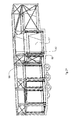
- the apparatus 1, as shown in Figure 1, further comprises a frame 29 arranged on the one hand for adequately containing the pallets 2 during movement and on the other hand for adequately stiffening the trailer 96.
- the frame 29 projects above the loading platform 3, and defines with the latter a loading space 94 in which it is possible to stow the pallets 2.
- the loading space 94 extends in height for approximately three thousand two hundred millimetres.
- the frame 29 comprises a plurality of upright elements 30, extending substantially vertically and positioned along longitudinal edges 95 of the loading platform 3 in directions substantially parallel to the axis Z.
- the upright elements 30 are aligned on a first line 44 and on a second line 45.
- the upright elements 30 belonging to the first line 44 facing respective upright elements 30 of the second line 45, define transverse pairs of upright elements 30.
- a first pair 36, a second pair 37, a third pair 38, a fourth pair 39, a fifth pair 40, a sixth pair 41, a seventh pair 42 and an eighth pair 43 of upright elements 30 are defined.
- the aforementioned pairs are arranged in such a way that between the first pair 36 and the second pair 37 a single loading station 86 is defined, between the second pair 37 and the third pair 38 a first double loading station 87 is defined, between the third pair 38 and the fourth pair 39 a first gap 99 is defined, between the fourth pair 39 and the fifth pair 40 there is defined a second double loading station 88, between the fifth pair 40 and the sixth pair 41 there is defined a second gap 100, between the sixth pair 41 and the seventh pair 42 a third double loading station 89 is defined and in that between the seventh pair 42 and the eighth pair 43 a third gap 101 is defined.
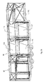
- the frame 29 is furthermore provided with a plurality of crosspiece elements 31 extending substantially horizontally, and comprising a plurality of longitudinal elongated elements 47 extending in directions substantially parallel to the axis Z and a plurality of transverse elongated elements 48 extending transversely with respect to the aforesaid axis Z.
- the longitudinal elongated elements 47 and the transverse elongated elements 48 are arranged in such a way as to define a first plane 97 substantially parallel to the loading platform 3 and located substantially at an end region 52 of the upright elements 30 and a second plane 98, parallel to the first plane 97, interposed between the first plane 97 and the loading platform 3.
- the longitudinal elongated elements 47 are arranged for longitudinally connecting the distinct pairs of upright elements 30, whilst the transverse elongated elements 48 transversely join the upright elements 30 of the first pair 36 and of the eighth pair 43.
- the frame 29 further comprises, in order to further increase the stiffness of the trailer 96 and to suitably contain the pallet 2, (as will be better disclosed below) a plurality of fixed reinforcing means 49, each comprising a pair of tubular elements 54 welded together so as to make an X-shaped structure.
- the reinforcing means 49 is positioned between the first plane 97 and the second plane 98 and extends substantially transversely with respect to the axis Z.
- the reinforcing means 49 is positioned between the upright elements 30 of the first pair 36, of the second pair 37 and of the eighth pair 43 and also substantially at the first gap 99, at the second gap 100 and at the third gap 101.
- the frame 29 further comprises further reinforcing means, for example movable gates 55 which also have the function of increasing the stiffness of the frame 29 and of acting as separating means between the pallets 2 positioned in the loading space 94.
- further reinforcing means for example movable gates 55 which also have the function of increasing the stiffness of the frame 29 and of acting as separating means between the pallets 2 positioned in the loading space 94.
- the movable gates 55 are positioned in use between the second plane 98 and the loading platform 3, and extend substantially transversely with respect to the axis Z.
- the movable gates 55 comprise a first movable gate 104 and a second movable gate 105, positioned respectively substantially at the first gap 99 and at the second gap 100.
- the first movable gate 104 separates the first double loading station 87 from the second double loading station 88
- the second movable gate 105 separates the second double loading station 88 from the third double loading station 89.
- the movable gates 55 each comprise a tubular structure 56 having a substantially square shape.
- the tubular structure 56 is provided with bars 57 positioned at the diagonals of the square defined by the tubular structure 56 that act as stiffening elements.
- the tubular structure 56 is furthermore provided with a first side 58 and with a second side 59, the first side 58 being positioned in use above the second side 59.
- the first side 58 is provided at the ends thereof with hinges 103 that are fixed to plates 123 that are removably fixed in shaped passages 62 obtained on surfaces facing the pairs of upright elements 30 between which the movable gates 55 are positioned.
- the movable gates 55 can be rotated, describing an angle of substantially 90°, between a first operating position in which they are arranged substantially horizontally and a second operating position in which they are arranged substantially vertically.
- the movable gates 55 when the movable gates 55 are in the first operating position they enable the passage of the pallets 2 along the loading platform 3, whereas when the movable gates 55 are in the second operating position, they act as separating elements of the loading stations and as stiffening elements of the loading space 94.
- the movable gates 55 rotate around an axis passing through the first horizontal side 58, in such a way that during the movement from the second operating position to the first operating position, the second horizontal side 59 approaches a rear portion 64 of the loading platform 3.
- the movable gates 55 are rotated by moving means that is not shown, for example gas springs or electric or pneumatic or hydraulic actuators.
- the apparatus 1 further comprises elevating means 65 arranged for lifting a pallet 2, shown in detail in Figures 5 to 11.
- the elevating means 65 comprise first elevating means 106, second elevating means 107 and third elevating means 108, positioned, in use, respectively in the first double loading station 87, in the second double loading station 88 and in the third double loading station 89.
- the elevating means 65 each comprise a frame 66 provided with a plurality of crosspieces 102, for example reciprocally welded rectangular section bars arranged transversely with respect to the longitudinal extent of the frame 66.
- the crosspieces 102 are shaped in such a way as to be able to be received, when the elevating means 65 rests on the loading platform 3, in housing means and in further housing means 141; in this way, when the pallets 2 are moved, and the elevating means 65 are placed on the loading platform 3, the crosspieces 102 are substantially at the same height as the loading platform 3 and do not hamper the transfer of the aforesaid pallets 2.
- the housing means which is not shown, is obtained in the third surface 10 and extends transversely substantially for the entire width of the loading platform 3. In this way, the housing means interrupts transversely the first row 15, the second row 16, the third row 17, the fourth row 18 and the fifth row 19 of the conveying rollers 12.
- the further housing means 141 ( Figure 3 and Figure 19) is obtained on an upper surface 142 of the platform 20 and extends substantially transversely for the entire width of the latter. In this way, the further housing means 141 interrupts transversely the further first row 26, the sixth row 27 and the seventh row 28 of further conveying rollers 23.
- the frame 66 is furthermore provided with a first longitudinal edge 69 and with a second longitudinal edge 70, from each of which a side panel 71 projects substantially vertically, extending in use substantially parallel to the axis Z.
- the side panels 71 have the function of retaining the load positioned on the pallet 2 laterally during movement.
- the frame 66 has a substantially rectangular shape, having an extent substantially equal to that of the pallet 2, and is provided with vertices 80, each of which is provided with a through hole 81 having a substantially vertical axis.
- the elevating means 65 furthermore comprises driving means 140 positioned near the vertices 80, arranged for moving substantially vertically the frame 66, moving it away from or towards the loading platform 3.
- Each of the driving means 140 comprises screw means, for example a trapezoidal thread worm screw 85, extending substantially vertically.
- Each trapezoidal thread worm screw 85 is fixed above to drilled flaps 109 ( Figure 4) projecting substantially horizontally in a direction substantially parallel to the axis Z, from the upright elements 30.
- Each trapezoidal thread worm screw 85 is arranged for engaging with a corresponding nut screw 79 substantially having the shape of a rectangular parallelpipedon.
- Each nut screw 79 is provided with a threaded hole 82, having an axis substantially coinciding with the axis of the through hole 81.
- Each nut screw 79 is supported by first supporting means 74 projecting vertically from the frame 66 and by second supporting means 75, opposite the first supporting means 74 projecting from an upper surface of the side panel 71.
- each trapezoidal thread worm screw 85 is positioned in such a way as to engage with the threaded hole 82, with the circular opening 84 and with the through hole 81.
- each trapezoidal thread worm screw 85 projects from below the loading platform 3.
- each trapezoidal thread worm screw 85 is connected together through flexible movement transmission means such as, for example, belts or chains that are not shown that rotate them substantially simultaneously.
- the flexible movement transmission means is driven by motor means that is not shown, for example of electric, pneumatic or hydraulic type.
- the trapezoidal thread worm screws are connected two by two, for example pairs of trapezoidal thread worm screws are connected together that are positioned longitudinally along the loading platform 3, and the motor means is provided with a control device, electronic or of another type, to ensure the simultaneity of the rotation.
- each screw is provided with a motor means, controlled for example electronically to ensure the simultaneity of the rotation.
- the first supporting element 74 comprises an external surface 90 on which are positioned two pairs of wheels 91 arranged for engaging with a vertical guide 92, for example in the shape of a bar with a square section with which the upright elements 30 are provided on a side surface 125, in particular the upright elements forming part of the first double loading station 88, of the second double loading station 89 and of the second double loading station 90.
- the elevating means 65 are each forced to move along the respective guide, thus avoiding undesired twisting.
- FIG. 12 With reference to Figure 12 and to Figure 13, there is shown a pallet 2 used for transport by air.
- the pallet 2 measures typically approximately two thousand four hundred and forty millimetres in width, about three thousand two hundred millimetres in length and about one thousand six hundred millimetres in width.
- the pallet 2 is provided with a base 111, for example made of aluminium, comprising folded edges 112 in which there are obtained openings 113, for example rectangular openings, in which forks of a fork lifting device that is not shown can be inserted.
- a base 111 for example made of aluminium, comprising folded edges 112 in which there are obtained openings 113, for example rectangular openings, in which forks of a fork lifting device that is not shown can be inserted.
- the base 111 is covered and retained by a suitable containing net 114 secured to the base 111 through a plurality of hooks that are not shown projecting from the folded edges 112.
- the first pallet 115 is then dragged by the motor rollers 13 from the third double loading station 89 to the first double loading station 87 and is more precisely located on the first elevating means 106, resting on the platform 20.
- the first fixing means is released that retains the platform 20 anchored to the second surface 9 and the platform 20 is fixed to the first elevating means 106 through second fixing means that is not shown with which it is provided.
- the first elevating means 106 is then driven that moves upwards the first pallet 115 and the platform 20.
- the first elevating means 106 lifts the platform 20 to the second operating position, i.e. to the first height Q1 ( Figure 15).
- the platform 20 ( Figure 17) moves downwards until it is positioned in the first operating position, the platform 20 is released by the first elevating means 106 and the latter is fixed by means of the first fixing means to the second surface 9.
- the second pallet 116 is dragged by the motor rollers 13 and by the further motor rollers 24 from the third double loading station 89 to the first double loading station 87 and is more precisely located on the first elevating means 106.
- the first elevating means 106 lifts the second pallet 116 to a first lifting height S1 ( Figure 19).
- a third pallet 117 ( Figure 20) can be located that similarly to the first two is dragged by the motor rollers 13 and by the further motor rollers 24 from the third double loading station 89 to the first double loading station 87, substantially below the second pallet 116.
- the further motor rollers 24 stop and go to the rest position, to enable suitable anchoring of the third pallet 117 on the platform 20.
- a fourth pallet 118 ( Figure 22) that is dragged by the motor rollers 13 from the third double loading station 89 to the second double loading station 88 can be located and more precisely it is located on the second elevating means 107.
- the second elevating means 107 ( Figure 23) lifts the fourth pallet 118 to a second lifting height S2 and maintains the pallet 118 lifted there at the second lifting height S2 that is the same as the first lifting height S1 when the second pallet 116 extends vertically as much as the fourth pallet 118.
- a sixth pallet 120 ( Figure 26) can be placed that is dragged by the motor rollers 13 to the third double loading station 89 and is more precisely placed on the third elevating means 108.
- the third elevating means 108 lifts the sixth pallet 120 to a third lifting height S3 and maintains the sixth pallet 120 lifted there, which third lifting height S3 is the same as the first lifting height S1 and as the second lifting height S2 when the sixth pallet 120 extends as far vertically as the fourth pallet 118 and the second pallet 116.
- the operation of the apparatus 1 when it is desired to unload the loading space 94 comprises the steps conducted in the reverse order that are disclosed when it is desired to load the loading space 94.
- the apparatus 1 is able to convey up to seven pallets, as opposed to only the four pallets of the known apparatuses.
- the elevating means can be positioned at different operating heights, enabling pallets having various heights to be positioned in the loading space, so as to optimise the space made available by the loading space 94.
Landscapes
- Engineering & Computer Science (AREA)
- Transportation (AREA)
- Mechanical Engineering (AREA)
- Warehouses Or Storage Devices (AREA)
- Intermediate Stations On Conveyors (AREA)
Abstract
Description
- The invention relates to apparatuses and methods for moving pallets, in particular for moving pallets for transport by air in industrial vehicles, such as, for example, trailer trucks or articulated trucks or the like used for air-truck transport.
- The pallets used in the transport by air industry comprise an aluminium rectangular base on which a load is placed that it is desired to transport.
- The load is subsequently covered and retained by an appropriate retaining net that is secured to the base by means of a plurality of hooks with which the latter is provided.
- The appropriately prepared pallets are then positioned on the trailer trucks that transfer them to an airport, where they are subsequently loaded on appropriate aircraft or cargo planes.
- Apparatuses are known for moving pallets for transport by air comprising trailer trucks provided with a trailer provided with a loading space delimited below by a planar loading platform and above and laterally by a stiff or flexible cover.
- The trailer is furthermore equipped with two or more parallel rows of conveying rollers extending along the longitudinal extent of the loading platform.
- The conveying rollers are each provided with a respective seat obtained in the loading platform.
- Each conveying roller is furthermore drivable vertically upwards and/or downwards and is rotatable by respective motor devices.
- When the conveying rollers are driven upwards, each projects from the respective seat and emerges from the loading platform in such a way as to move the pallets along the latter, whilst when the conveying rollers are driven downwards they reposition themselves in the respective seats, enabling the respective pallets to be fixed on the loading platform.
- The operation of the known apparatuses is as follows: when it is desired to load pallets for transport by air into the loading space of a trailer truck, the conveying rollers that emerge from the respective seats are driven upwards and a first pallet is deposited on the rollers.
- At this point, the conveying rollers are rotated so that the first pallet resting thereupon is transferred to a front end of the loading space where it is placed in a first loading station.
- It is now possible to load into the loading space a second pallet that is conveyed onto the loading platform by the conveying rollers until it is positioned in a second loading station adjacent to the first loading station, and so on also for the subsequent pallets until the loading stations obtained in the aforementioned loading space are full.
- Once all the pallets have been loaded that are stowable in the loading space, rotation is interrupted and the conveying rollers are driven downwards to enable the pallets to be anchored stably on the loading platform.
- On the other hand, when it is desired to unload the pallets, the operations that are necessary for loading the pallets are simply conducted in reverse order.
- A drawback of the known vehicles used for air-truck transport is the limited number of pallets that are transportable by each trailer truck, as they cannot be superimposed without exceeding the overall dimension limits set by the European and Swiss highway codes.
- In fact, known apparatuses enable only four pallets at a time to be transported.
- In this way, numerous journeys and/or several trailer trucks are required for transporting a sufficient number of pallets to fill a hold of a cargo plane, which entails significant transport costs to be borne by airlines.
- A further drawback of the known vehicles used for air-truck transport is the inability to exploit the loading space adequately.
- In fact, in the known apparatuses a considerable upper portion of the loading space remains unoccupied, a portion that is not occupied by the pallets of standard dimensions.
- This drawback is further accentuated if pallets are loaded having a vertical extent that is less than that of pallets of standard dimensions.
- An object of the invention is to improve the apparatuses and methods for transport by air inside trailer trucks or articulated trucks or the like used for air-truck transport. A further object is to increase the number of pallets that are transportable by a single trailer truck, to reach a maximum of 7 ULBs that are 160 cm high.
- A still further object is to optimise the space available in the loading space.
- Still another object is to limit the transport costs of the pallets by reducing the number of motor vehicles in circulation.
- In a first aspect of the invention, an apparatus is provided for moving pallets for transportation by air in a loading space of a land vehicle, said apparatus being provided with rolling means for moving substantially horizontally said pallets along a loading platform with which said loading space is provided, characterised in that it further comprises elevating means for elevating said pallets away from or towards said loading platform.
- In a second aspect of the invention, there is provided a method for loading pallets for transport by air in a loading space of a land vehicle comprising the following steps in sequence:
- moving a pallet along a loading platform of said loading space, said loading platform being positioned at a height (Q3);
- lifting said pallet away from said loading platform to a lifting height (S1), said lifting height (S1) being greater than said height (Q3);
- maintaining said pallet lifted at said lifting height (S1);
- further moving a further pallet along said loading platform below said pallet.
- In a third aspect of the invention, there is provided a method for unloading pallets for transport by air from a loading space of a land vehicle comprising the following steps in sequence:
- moving a pallet along a loading platform of said loading space, said loading platform being positioned at a height (Q3);
- removing said pallet from said loading platform;
- lowering towards said loading platform a further pallet positioned at a further height (S1) to said height (Q3), said height (Q3) being lower than said further height (S1);
- further moving said further pallet along said loading platform (3);
- further removing said further pallet.
- In a fourth aspect of the invention, a method is provided for loading pallets for transport by air in a loading space of a land vehicle comprising the following steps in sequence:
- moving said pallet along a part of a loading platform of said loading space, said part being positioned at a height (Q3);
- lifting said pallet away from said part at a further height (Q1), said further height (Q1) being greater than said height (Q3);
- maintaining said pallet lifted at said height (Q1);
- further moving said pallet to a further part of said loading platform to a storage position, said further part being positioned substantially at said further height (Q1).
- In a fifth aspect of the invention, a method is provided for unloading pallets for transport by air from a loading space of a land vehicle comprising the following steps in sequence:
- moving said pallet along a part of a loading platform of said loading space, said part being positioned at a height (Q1);
- lowering said pallet towards or away from a further part of said loading platform, said further part being positioned at a further height (Q3) that is less than said height (Q1);
- further moving said pallet along said further part.
- Owing to these aspects of the invention, it is possible to obtain apparatuses and methods for moving pallets for transport by air that enable the number of pallets to be increased that are stowable in a loading space of a land vehicle.
- In fact, the pallets, once they are positioned inside the loading space, are located on the elevating means that lift them up to a certain height, moving them away from the loading platform.
- This enables further pallets to be positioned below each of the elevating means until the loading platform is completely filled.
- In this way, it is possible to increase the number of loadable pallets, inasmuch as the latter can be positioned both on the loading platform and on an additional loading plane made by the elevating means.
- Furthermore, as the elevating means can lift up from the loading platform to any height, it is possible to locate in the loading space pallets having various vertical dimensions, exploiting the loading space in a more efficient manner.
- The invention can be better understood and implemented with reference to the attached drawings that illustrate an embodiment thereof by way of non-limitative example, in which:
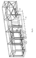
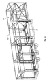
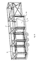
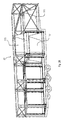
- Figure 1 is a perspective view of an apparatus for moving pallets by transport by air;
- Figure 2 is a fragmentary frontal perspective view of the apparatus in Figure 1;
- Figure 3 is a fragmentary perspective view of a platform of the apparatus in Figure 1;
- Figure 4 is a fragmentary perspective view of the movable gates of the apparatus in Figure 1;
- Figure 5 is a lateral view of an elevating unit of the apparatus in Figure 1;
- Figure 6 is a frontal view of the elevating unit in Figure 5;
- Figure 7 is a view from above of the elevating unit in Figure 5;
- Figure 8 is a perspective view of the elevating unit in Figure 5;
- Figure 9 is a perspective view of a detail of the elevating unit in Figure 5;
- Figure 10 is an enlarged detail of Figure 9;
- Figure 11 is a fragmentary frontal view of an enlarged detail of the elevating unit in Figure 5;
- Figure 12 is a frontal view of a pallet for transport by air;
- Figure 13 is a lateral view of the pallet in Figure 12;
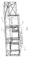
- Figure 14 is a perspective view of the apparatus in Figure 1 in a first operative configuration;
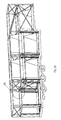
- Figure 15 is a perspective view of the apparatus in Figure 1 in a second operative configuration;
- Figure 16 is a perspective view of the apparatus in Figure 1 in a third operative configuration;
- Figure 17 is a perspective view of the apparatus in Figure 1 in a fourth operative configuration;
- Figure 18 is a perspective view of the apparatus in Figure 1 in a fifth operative configuration;
- Figure 19 is a perspective view of the apparatus in Figure 1 in a sixth operative configuration;
- Figure 20 is a perspective view of the apparatus in Figure 1 in a seventh operative configuration;
- Figure 21 is a perspective view of the apparatus in Figure 1 in an eighth operative configuration;
- Figure 22 is a perspective view of the apparatus in Figure 1 in a ninth operative configuration;
- Figure 23 is a perspective view of the apparatus in Figure 1 in a tenth operative configuration;
- Figure 24 is a perspective view of the apparatus in Figure 1 in an eleventh operative configuration;
- Figure 25 is a perspective view of the apparatus in Figure 1 in a twelfth operative configuration.
- Figure 26 is a perspective view of the apparatus in Figure 1 in a thirteenth operative configuration;
- Figure 27 is a perspective view of the apparatus in Figure 1 in a fourteenth operative configuration.
- With reference to Figure 1, there is shown an apparatus 1 for storing air pallets 2 (Figures 12 and 13) mounted on a
trailer 96 of a land vehicle that is not shown, for example a trailer truck extending for about four thousand and forty millimetres in height. - The apparatus 1 is provided with a
loading platform 3 extending along a substantially longitudinal axis Z. - In a preferred embodiment, the
loading platform 3 extends in width for about two thousand five hundred and fifty millimetres. - The
loading platform 3 comprises a first portion 4, a second portion 5 and a third portion 6, the second portion 5 being interposed between the first portion 4 and the third portion 6. - The first portion 4 and the second portion 5 are connected together by means of a step 7 whereas the second portion 5 and the third portion 6 are connected together by a further step 11.
- In this way, the first portion 4, the second portion 5 and the third portion 6 are reciprocally positioned on different planes.
- In other words, the first portion 4, the second portion 5 and the third portion 6 are located respectively at a first height Q1, at a second height Q2 and at a third height Q3.
- In particular, the first height Q1 is greater than the third height Q3, which in turn is greater than the second height Q2.
- Furthermore, the first portion 4, the second portion 5 and the third portion 6 respectively comprise a first surface 8, a
second surface 9 and athird surface 10 that are substantially planar. - The first surface 8 and the
third surface 10, are each provided with a plurality of conveyingrollers 12 having horizontal axes that are substantially perpendicular to the axis Z. - The conveying
rollers 12 comprisemotor rollers 13 and free to rotate rollers 14 (Figure 2), each roller being housed in a respective seat that is not shown. - The
motor rollers 13 are arranged along afirst row 15 extending along the axis Z, whilst the free to rotaterollers 14 are arranged along asecond row 16, athird row 17, afourth row 18 and afifth row 19. - Furthermore, the
second row 16 and thethird row 17 are close to one another and extend along an axis that is substantially parallel to the axis Z, just as thefourth row 18 and thefifth row 19 are close to one another and develop along a further axis that is substantially parallel to the axis Z. - In other words, the
second row 16 with thethird row 17 and thefourth row 18 with thefifth row 19 are positioned on opposite parts with respect to thefirst row 15. - The
motor rollers 13 and the free to rotaterollers 14 are movable vertically between a rest position, in which they are located in the respective seats, and an operating position in which they emerge from the respective seats and consequently from theloading platform 3. - In particular, the
motor rollers 13 and the free to rotaterollers 14 are driven by driving devices that are not shown, for example driving devices that use pneumatic means to move themotor rollers 13 and the free to rotaterollers 14 from the rest position to the operating position, and which use the force of gravity to take themotor rollers 13 and the free to rotaterollers 14 from the operating position to the rest position. - Furthermore, the
motor rollers 13 are rotated by means of further driving devices, that are not shown, for example of electric type, whilst the free to rotaterollers 14 rotate freely around a rotation axis thereof. - The
second surface 9 comprises a platform 20 (Figure 3), with a substantially rectangular shape, that is vertically movable between a first operating position in which it is fixed by means of first fixing means, which is not shown, to thesecond surface 9, and a second operating position in which it is lifted with respect to the aforementionedsecond surface 9, as will be disclosed better below. - When the
platform 20 is positioned in the first operating position it is at a height that is substantially the same as the third height Q3 of thethird surface 10. - In this way, the first surface 8 defines a
first loading platform 21, whilst theplatform 20 and thethird surface 10 define a second substantiallyplanar loading platform 22 shown in Figure 1. - The
platform 20 is furthermore provided with further conveyingrollers 23 comprisingfurther motor rollers 24 and further free to rotaterollers 25 positioned in corresponding seats that are not shown. - In particular, the
further motor rollers 24 are arranged according to a furtherfirst row 26 that is merely the continuation along the axis Z of thefirst row 15. - On the other side, the further free to rotate
rollers 25 are arranged in two rows, respectively along asixth row 27 and aseventh row 28 extending substantially parallel to and on opposite sides to the furtherfirst row 26. - In particular, the
sixth row 27 and theseventh row 28 are the continuation respectively of thesecond row 16 and of thefifth row 19. - The
further motor rollers 24 are drivable vertically between a further rest position and a further operating position and are rotated in a similar manner to themotor rollers 13, just as the further free to rotaterollers 25 are drivable between a further rest position and a further operating position in a similar manner to the free to rotaterollers 14. - The apparatus 1, as shown in Figure 1, further comprises a
frame 29 arranged on the one hand for adequately containing thepallets 2 during movement and on the other hand for adequately stiffening thetrailer 96. - The
frame 29 projects above theloading platform 3, and defines with the latter aloading space 94 in which it is possible to stow thepallets 2. - In a preferred embodiment, the
loading space 94 extends in height for approximately three thousand two hundred millimetres. - The
frame 29 comprises a plurality ofupright elements 30, extending substantially vertically and positioned alonglongitudinal edges 95 of theloading platform 3 in directions substantially parallel to the axis Z. - In this way, the
upright elements 30 are aligned on a first line 44 and on asecond line 45. - The
upright elements 30 belonging to the first line 44 facing respectiveupright elements 30 of thesecond line 45, define transverse pairs ofupright elements 30. - In particular, from a
front portion 46 of theloading platform 3, afirst pair 36, asecond pair 37, athird pair 38, afourth pair 39, afifth pair 40, asixth pair 41, aseventh pair 42 and aneighth pair 43 ofupright elements 30 are defined. - In particular, the aforementioned pairs are arranged in such a way that between the
first pair 36 and the second pair 37 asingle loading station 86 is defined, between thesecond pair 37 and the third pair 38 a firstdouble loading station 87 is defined, between thethird pair 38 and the fourth pair 39 afirst gap 99 is defined, between thefourth pair 39 and thefifth pair 40 there is defined a seconddouble loading station 88, between thefifth pair 40 and thesixth pair 41 there is defined asecond gap 100, between thesixth pair 41 and the seventh pair 42 a thirddouble loading station 89 is defined and in that between theseventh pair 42 and the eighth pair 43 athird gap 101 is defined. - The
frame 29 is furthermore provided with a plurality ofcrosspiece elements 31 extending substantially horizontally, and comprising a plurality of longitudinalelongated elements 47 extending in directions substantially parallel to the axis Z and a plurality of transverseelongated elements 48 extending transversely with respect to the aforesaid axis Z. - The longitudinal
elongated elements 47 and the transverseelongated elements 48 are arranged in such a way as to define afirst plane 97 substantially parallel to theloading platform 3 and located substantially at anend region 52 of theupright elements 30 and asecond plane 98, parallel to thefirst plane 97, interposed between thefirst plane 97 and theloading platform 3. - In particular, the longitudinal
elongated elements 47 are arranged for longitudinally connecting the distinct pairs ofupright elements 30, whilst the transverseelongated elements 48 transversely join theupright elements 30 of thefirst pair 36 and of theeighth pair 43. - The
frame 29 further comprises, in order to further increase the stiffness of thetrailer 96 and to suitably contain thepallet 2, (as will be better disclosed below) a plurality of fixed reinforcingmeans 49, each comprising a pair oftubular elements 54 welded together so as to make an X-shaped structure. - The reinforcing means 49 is positioned between the
first plane 97 and thesecond plane 98 and extends substantially transversely with respect to the axis Z. - In particular, the reinforcing
means 49 is positioned between theupright elements 30 of thefirst pair 36, of thesecond pair 37 and of theeighth pair 43 and also substantially at thefirst gap 99, at thesecond gap 100 and at thethird gap 101. - The
frame 29 further comprises further reinforcing means, for examplemovable gates 55 which also have the function of increasing the stiffness of theframe 29 and of acting as separating means between thepallets 2 positioned in theloading space 94. - The
movable gates 55, shown in detail in Figure 4, are positioned in use between thesecond plane 98 and theloading platform 3, and extend substantially transversely with respect to the axis Z. - The
movable gates 55 comprise a firstmovable gate 104 and a secondmovable gate 105, positioned respectively substantially at thefirst gap 99 and at thesecond gap 100. In particular, the firstmovable gate 104 separates the firstdouble loading station 87 from the seconddouble loading station 88, whilst the secondmovable gate 105 separates the seconddouble loading station 88 from the thirddouble loading station 89. - The
movable gates 55 each comprise atubular structure 56 having a substantially square shape. - The
tubular structure 56 is provided withbars 57 positioned at the diagonals of the square defined by thetubular structure 56 that act as stiffening elements. - The
tubular structure 56 is furthermore provided with afirst side 58 and with asecond side 59, thefirst side 58 being positioned in use above thesecond side 59. - The
first side 58 is provided at the ends thereof withhinges 103 that are fixed toplates 123 that are removably fixed in shapedpassages 62 obtained on surfaces facing the pairs ofupright elements 30 between which themovable gates 55 are positioned. - In this way, the
movable gates 55 can be rotated, describing an angle of substantially 90°, between a first operating position in which they are arranged substantially horizontally and a second operating position in which they are arranged substantially vertically. - In particular, when the
movable gates 55 are in the first operating position they enable the passage of thepallets 2 along theloading platform 3, whereas when themovable gates 55 are in the second operating position, they act as separating elements of the loading stations and as stiffening elements of theloading space 94. - In particular, the
movable gates 55 rotate around an axis passing through the firsthorizontal side 58, in such a way that during the movement from the second operating position to the first operating position, the secondhorizontal side 59 approaches a rear portion 64 of theloading platform 3. - The
movable gates 55 are rotated by moving means that is not shown, for example gas springs or electric or pneumatic or hydraulic actuators. - Lastly, when the
movable gates 55 are in the second position, they are fixed between the respective gaps through anchoring means 63 (Figure 2). - The apparatus 1 further comprises elevating means 65 arranged for lifting a
pallet 2, shown in detail in Figures 5 to 11. - The elevating means 65 comprise first elevating
means 106, second elevating means 107 and third elevating means 108, positioned, in use, respectively in the firstdouble loading station 87, in the seconddouble loading station 88 and in the thirddouble loading station 89. - The elevating means 65 each comprise a
frame 66 provided with a plurality ofcrosspieces 102, for example reciprocally welded rectangular section bars arranged transversely with respect to the longitudinal extent of theframe 66. - The
crosspieces 102 are shaped in such a way as to be able to be received, when the elevatingmeans 65 rests on theloading platform 3, in housing means and in further housing means 141; in this way, when thepallets 2 are moved, and the elevatingmeans 65 are placed on theloading platform 3, thecrosspieces 102 are substantially at the same height as theloading platform 3 and do not hamper the transfer of theaforesaid pallets 2. - The housing means, which is not shown, is obtained in the
third surface 10 and extends transversely substantially for the entire width of theloading platform 3. In this way, the housing means interrupts transversely thefirst row 15, thesecond row 16, thethird row 17, thefourth row 18 and thefifth row 19 of the conveyingrollers 12. - The further housing means 141 (Figure 3 and Figure 19) is obtained on an
upper surface 142 of theplatform 20 and extends substantially transversely for the entire width of the latter. In this way, the further housing means 141 interrupts transversely the furtherfirst row 26, thesixth row 27 and theseventh row 28 of further conveyingrollers 23. - The
frame 66 is furthermore provided with a firstlongitudinal edge 69 and with a secondlongitudinal edge 70, from each of which aside panel 71 projects substantially vertically, extending in use substantially parallel to the axis Z. - The
side panels 71 have the function of retaining the load positioned on thepallet 2 laterally during movement. - The
frame 66 has a substantially rectangular shape, having an extent substantially equal to that of thepallet 2, and is provided withvertices 80, each of which is provided with a throughhole 81 having a substantially vertical axis. - The elevating means 65 furthermore comprises driving means 140 positioned near the
vertices 80, arranged for moving substantially vertically theframe 66, moving it away from or towards theloading platform 3. - Each of the driving means 140 comprises screw means, for example a trapezoidal
thread worm screw 85, extending substantially vertically. - Each trapezoidal
thread worm screw 85 is fixed above to drilled flaps 109 (Figure 4) projecting substantially horizontally in a direction substantially parallel to the axis Z, from theupright elements 30. - Each trapezoidal
thread worm screw 85 is arranged for engaging with acorresponding nut screw 79 substantially having the shape of a rectangular parallelpipedon. - Each
nut screw 79 is provided with a threadedhole 82, having an axis substantially coinciding with the axis of the throughhole 81. - Each
nut screw 79 is supported by first supporting means 74 projecting vertically from theframe 66 and by second supporting means 75, opposite the first supporting means 74 projecting from an upper surface of theside panel 71. - With the first supporting means 74 and with the second supporting means 75 in an
intermediate region 110 there is furthermore associated a shapedelement 83 provided with acircular opening 84, having the function of stiffening the driving means 140. - In use, each trapezoidal
thread worm screw 85 is positioned in such a way as to engage with the threadedhole 82, with thecircular opening 84 and with the throughhole 81. - Furthermore, in use, a
lower portion 124 of each trapezoidalthread worm screw 85 projects from below theloading platform 3. - The
lower portions 124 of each trapezoidalthread worm screw 85 are connected together through flexible movement transmission means such as, for example, belts or chains that are not shown that rotate them substantially simultaneously. - The flexible movement transmission means is driven by motor means that is not shown, for example of electric, pneumatic or hydraulic type.
- In this way, after a rotation of each trapezoidal thread worm screw, the corresponding nut screw is forced to move upwards or downwards, dragging with it the
frame 66. - In an embodiment that is not shown, the trapezoidal thread worm screws are connected two by two, for example pairs of trapezoidal thread worm screws are connected together that are positioned longitudinally along the
loading platform 3, and the motor means is provided with a control device, electronic or of another type, to ensure the simultaneity of the rotation. - In a further alternative embodiment that is not shown, each screw is provided with a motor means, controlled for example electronically to ensure the simultaneity of the rotation.
- Lastly, the first supporting
element 74 comprises anexternal surface 90 on which are positioned two pairs ofwheels 91 arranged for engaging with avertical guide 92, for example in the shape of a bar with a square section with which theupright elements 30 are provided on aside surface 125, in particular the upright elements forming part of the firstdouble loading station 88, of the seconddouble loading station 89 and of the seconddouble loading station 90. - In this way, during driving, the elevating
means 65 are each forced to move along the respective guide, thus avoiding undesired twisting. - With reference to Figure 12 and to Figure 13, there is shown a
pallet 2 used for transport by air. - The
pallet 2 measures typically approximately two thousand four hundred and forty millimetres in width, about three thousand two hundred millimetres in length and about one thousand six hundred millimetres in width. - The
pallet 2 is provided with abase 111, for example made of aluminium, comprising foldededges 112 in which there are obtainedopenings 113, for example rectangular openings, in which forks of a fork lifting device that is not shown can be inserted. - Once a load has been deposited on the
base 111, the latter is covered and retained by a suitable containing net 114 secured to the base 111 through a plurality of hooks that are not shown projecting from the folded edges 112. - The operation of the apparatus 1, shown in Figures 14 to 27, when it is desired to load
loading space 94, is as follows: initially the conveyingrollers 12 and the further conveyingrollers 23 are in the rest position, themovable gates 55 are in the first operating position, i.e. they are lifted, and theplatform 20 is in the first operating position at the third height Q3. - When a
first pallet 115 is positioned on theloading platform 3, themotor rollers 13 and the free to rotaterollers 14 of the thirddouble loading station 89 and of the seconddouble loading station 88 and thefurther motor rollers 24 and the further free to rotaterollers 25 of the firstdouble loading station 87 are commanded that are taken to the operating position and themotor rollers 13 and thefurther rollers 24 are rotated. - The
first pallet 115 is then dragged by themotor rollers 13 from the thirddouble loading station 89 to the firstdouble loading station 87 and is more precisely located on the first elevatingmeans 106, resting on theplatform 20. - At this point, the first fixing means is released that retains the
platform 20 anchored to thesecond surface 9 and theplatform 20 is fixed to the first elevating means 106 through second fixing means that is not shown with which it is provided. - The first elevating
means 106 is then driven that moves upwards thefirst pallet 115 and theplatform 20. - In particular, the first elevating means 106 lifts the
platform 20 to the second operating position, i.e. to the first height Q1 (Figure 15). - The
further motor rollers 24, by rotating, drag thefirst pallet 115, positioning it in the single loading station 86 (Figure 16). - Once the
first pallet 115 has been arranged, the platform 20 (Figure 17) moves downwards until it is positioned in the first operating position, theplatform 20 is released by the first elevatingmeans 106 and the latter is fixed by means of the first fixing means to thesecond surface 9. - It is now possible to place a second pallet 116 (Figure 18) on the
loading platform 3. - The
second pallet 116 is dragged by themotor rollers 13 and by thefurther motor rollers 24 from the thirddouble loading station 89 to the firstdouble loading station 87 and is more precisely located on the first elevatingmeans 106. - The first elevating means 106 lifts the
second pallet 116 to a first lifting height S1 (Figure 19). - At this point on the loading platform 3 a third pallet 117 (Figure 20) can be located that similarly to the first two is dragged by the
motor rollers 13 and by thefurther motor rollers 24 from the thirddouble loading station 89 to the firstdouble loading station 87, substantially below thesecond pallet 116. - Once the
third pallet 117 has reached the firstdouble loading station 88 thefurther motor rollers 24 stop and go to the rest position, to enable suitable anchoring of thethird pallet 117 on theplatform 20. - It is now possible to rotate the first movable gate 104 (Figure 21), taking it to the second operating position and using the anchoring means 63 to fix it to the
first gap 99. - Subsequently, on the loading platform 3 a fourth pallet 118 (Figure 22) that is dragged by the
motor rollers 13 from the thirddouble loading station 89 to the seconddouble loading station 88 can be located and more precisely it is located on the second elevatingmeans 107. - The second elevating means 107 (Figure 23) lifts the
fourth pallet 118 to a second lifting height S2 and maintains thepallet 118 lifted there at the second lifting height S2 that is the same as the first lifting height S1 when thesecond pallet 116 extends vertically as much as thefourth pallet 118. - It is now possible to load a fifth pallet 119 (Figure 24) that is conveyed by the
motor rollers 13 from the thirddouble loading station 89 to the seconddouble loading station 88, substantially below thefourth pallet 118. - At this point, rotation of the
motor rollers 13 of the seconddouble loading station 88 stops, themotor rollers 13 and the free to rotaterollers 14 of the seconddouble loading station 88 are placed in the rest position and the second movable gate 105 (Figure 25) is rotated, placing it in the second operating position, and using the anchoring means 63 it is fixed to thesecond gap 100. - Subsequently, on the loading platform 3 a sixth pallet 120 (Figure 26) can be placed that is dragged by the
motor rollers 13 to the thirddouble loading station 89 and is more precisely placed on the third elevatingmeans 108. - The third elevating means 108 lifts the
sixth pallet 120 to a third lifting height S3 and maintains thesixth pallet 120 lifted there, which third lifting height S3 is the same as the first lifting height S1 and as the second lifting height S2 when thesixth pallet 120 extends as far vertically as thefourth pallet 118 and thesecond pallet 116. - It is now possible to load a seventh pallet 121 (Figure 27) that is conveyed by the
motor rollers 13 to the thirddouble loading station 89, substantially below thesixth pallet 120. - At this point, rotation of the
motor rollers 13 is blocked and the conveyingrollers 12 are taken to the rest position. It is now possible to shut theloading space 94 by means of a rear door that is not shown, with which thetrailer 96 is provided. - The operation of the apparatus 1 when it is desired to unload the
loading space 94, comprises the steps conducted in the reverse order that are disclosed when it is desired to load theloading space 94. - It should be noted that the apparatus 1 is able to convey up to seven pallets, as opposed to only the four pallets of the known apparatuses.
- It should furthermore be noted that the elevating means can be positioned at different operating heights, enabling pallets having various heights to be positioned in the loading space, so as to optimise the space made available by the
loading space 94.
Claims (50)
- Apparatus for moving pallets (2, 115, 116, 117, 118, 119, 120, 121) for transport by air in a loading space (94) of a land vehicle, said apparatus being provided with rolling means (12, 23) for moving substantially horizontally said pallets (2, 115, 116, 117, 118, 119, 120, 121) along a loading platform (3) with which said loading space (94) is provided, characterised in that it further comprises elevating means (20; 65) for elevating said pallets (2, 115, 116, 117, 118, 119, 120, 121) away from or towards said loading platform (3).
- Apparatus according to claim 1, wherein said elevating means (65) comprises frame means (66) arranged for supporting said pallets (2, 115, 116, 117, 118, 119, 120, 121).
- Apparatus according to claim 2, wherein said frame means (66) comprises containing means (71) for retaining laterally said pallets (2, 115, 116, 117, 118, 119, 120, 121) during the movement of said land vehicle.
- Apparatus according to claim 2, or 3, wherein said frame means (66) has a substantially rectangular shape provided with vertices (80) wherein hole means (81) are obtained.
- Apparatus according to any one of claims 2 to 4, wherein said frame means (66) comprises a plurality of transverse elements (102) arranged substantially transversely to a longitudinal extent of said frame means (66).
- Apparatus according to any one of claims 2 to 5, wherein said elevating means (65) comprises driving means (140) arranged for lifting said frame means (66).
- Apparatus according to claim 6, wherein said driving means (140) is positioned substantially at said vertices (80).
- Apparatus according to claim 6, or 7, wherein said driving means (140) comprises spiral means (9).
- Apparatus according to claims 4 and 8, wherein said spiral means (79) comprises threaded hole means (82) substantially aligned on said hole means (81).
- Apparatus according to claim 8, or 9, wherein said spiral means (79) is supported by supporting means (74, 75) projecting from an upper surface of said frame means (66).
- Apparatus according to claim 10, wherein an intermediate region (110) of said supporting means (74, 75) supports a drilled element (83) interposed between said spiral means (79) and said frame means (66).
- Apparatus according to any one of claims 6 to 11, wherein said driving means (140) comprises screw means (85).
- Apparatus according to claim 12, wherein said screw means (85) extends substantially vertically and is arranged for engaging with said threaded hole means (82) and traverses said drilled element (83) and said hole means (81).
- Apparatus according to any one of claims 2 to 13, wherein said elevating means (65) comprises flexible driving means arranged for rotating said screw means (85).
- Apparatus according to claim 14, wherein said flexible driving means engages with portions (124) of said screw means (85) projecting from said hole means (81) substantially below said loading platform (3).
- Apparatus according to claim 14, or 15, wherein said flexible driving means connects distinct pairs of said screw means (85).
- Apparatus according to claim 14, or 15, wherein said flexible driving means connects said screw means (85) reciprocally.
- Apparatus according to claim 14, or 15, wherein said screw means are each controlled by respective motor means.
- Apparatus according to any one of claims 2 to 18, wherein said elevating means (65) is provided with sliding block means (91) arranged for sliding along guide means (92).
- Apparatus according to claim 19, wherein said guide means (92) is associated with upright means (30) projecting vertically from said loading platform (3).
- Apparatus according to any one of claims 2 to 20, wherein said elevating means (65) comprises first elevating means (106), second elevating means (107) and third elevating means (108).
- Apparatus according to claim 21, wherein said first elevating means (106), said second elevating means (107) and said third elevating means (108) are positioned respectively in a first loading station (87), in a second loading station (88) and in a third loading station (89) that are consecutive along said loading platform (3) and are defined by said upright means (30).
- Apparatus according to any preceding claim, and further comprising a frame (29) projecting from said loading platform (3) to define said loading space (94).
- Apparatus according to claim 23, wherein said frame (29) is provided with reinforcing means (49) positioned substantially transversely with respect to said loading platform (3) and arranged for blocking the sliding of said pallets (2, 115, 116, 117, 118, 119, 120, 121) along said loading platform (3).
- Apparatus according to claim 24, wherein said reinforcing means (49) is positioned in an upper region of said loading space (94).
- Apparatus according to any one of claims 23 to 25, wherein said frame (29) comprises further reinforcing means (55) for further stiffening said loading space (94).
- Apparatus according to claim 26, wherein said further reinforcing means (55) is positioned between said first loading station (87) and said second loading station (88) and between said second loading station (88) and said third loading station (89).
- Apparatus according to claim 26, or 27, wherein said further reinforcing means (55) is movable between a vertical position and a horizontal position through further driving means.
- Apparatus according to claim 28, wherein said further driving means comprises gas springs.
- Apparatus according to claim 28 or 29, wherein said further reinforcing means is provided with anchoring means (63) arranged for anchoring it to said upright means (30), when said further reinforcing means (55) is in said vertical position.
- Apparatus according to any preceding claim, wherein said elevating means (20; 65) is received in housing means arranged transversely to said loading platform (3), so that when the elevating means (65) is at the lowest position, said crosspieces (102) are substantially coplanar with said loading platform (3).
- Apparatus according to any preceding claim, wherein said elevating means (20) comprises a platform (20) provided with further rolling means (23).
- Apparatus according to claim 32, wherein said platform (20) is interposed between said first elevating means (106) and a portion (5) of said loading platform (3).
- Apparatus according to claim 32, or 33, wherein said platform (20) is provided with fixing means arranged for fixing it to said portion (5).
- Apparatus according to any one of claims 32 to 34, wherein said platform (20) is provided with further fixing means arranged for fixing it to said first elevating means (106).
- Apparatus according to any one of claims 33 to 35, wherein said platform (20) is movable away from or towards said portion (5) by said first elevating means (106).
- Apparatus according to any one of claims 32 to 36, wherein said platform (20) is positioned at a recess (5) of said loading platform (3) in such a way as to be, in the lowered position, substantially coplanar with a remaining part (6) of said loading platform (3).
- Apparatus according to any one of claims 32 to 37 as appended to claim 21, wherein in said platform (20) further housing means (141) is obtained that is arranged so as to receive said crosspieces (102) when said first elevating means (106) is in the lowest position.
- Apparatus according to any preceding claim, wherein said loading platform measures approximately 2550 millimetres in width.
- Apparatus according to any preceding claim, wherein said land vehicle has a height measuring approximately 4040 millimetres.
- Method for loading a pallet (2, 115, 116, 117, 118, 119, 120, 121) for transport by air in a loading space (94) of a land vehicle comprising the following steps in sequence:• moving said pallet (2, 115, 116, 117, 118, 119, 120, 121) along a part (22) of a loading platform (3) of said loading space (94), said part (22) being positioned at a height (Q3);• lifting said pallet (2, 115, 116, 117, 118, 119, 120, 121) away from said part (22) to a further height (Q1), said further height (Q1) being greater than said height (Q3);• maintaining said pallet (2, 115, 116, 117, 118, 119, 120, 121) lifted at said height (Q1);• further moving said pallet (2, 115, 116, 117, 118, 119, 120, 121) to a further part (21) of said loading platform (3) to a storage position (86), said further part (21) being positioned substantially at said further height (Q2).
- Method for unloading a pallet (2, 115, 116, 117, 118, 119, 120, 121) for transport by air from a loading space (94) of a land vehicle comprising the following steps in sequence:• moving said pallet (2, 115, 116, 117, 118, 119, 120, 121) along a part (21) of a loading platform (3) of said loading space (94), said part (21) being positioned at a height (Q1);• lowering said pallet (2, 115, 116, 117, 118, 119, 120, 121) towards a further part (22) of said loading platform (3), said further part (22) being positioned at a further height (Q3) that is less than said height (Q1);• further moving said pallet (2, 115, 116, 117, 118, 119, 120, 121) along said further part (22).
- Method for loading pallets (2, 115, 116, 117, 118, 119, 120, 121) for transport by air in a loading space (94) of a land vehicle comprising the following steps in sequence:• moving a pallet (115) along a loading platform (3) of said loading space (94), said loading platform (3) being positioned at a height (Q3);• lifting said pallet (115) away from said loading platform (3) to a lifting height (S1), said lifting height (S1) being greater than said height (Q3) ;• maintaining said pallet (115) lifted at said lifting height (S1);• further moving a further pallet (116) along said loading platform (3) below said pallet (115).
- Method according to claim 43, wherein said further moving comprises sliding said further pallet (116) until it is substantially at said pallet (115).
- Method according to claim 44, wherein after said sliding positioning said further pallet (116) substantially below said pallet (115) is provided.
- Method according to claim 45, comprising repeating said moving, said lifting, said maintaining, said further moving, said sliding, said positioning, until the loading stations (87, 88, 89) provided in said loading space (94) have been filled.
- Method according to claim 46, wherein said loading stations (87, 88, 89) are six.
- Method for unloading pallets (2, 115, 116, 117, 118, 119, 120, 121) for transport by air from a loading space (94) of a land vehicle comprising the following steps in sequence:• moving un pallet (116) along a loading platform (3) of said loading space (94), said loading platform (3) being positioned at a height (Q3);• removing said pallet (116) from said loading platform (3);• lowering towards said loading platform (3) a further pallet (115) positioned at a further height (S1) to said height (Q3), said height (Q3) being lower than said further height (S1);• further moving said further pallet (115) along said loading platform (3);• further removing said further pallet (115).
- Method according to claim 48, comprising repeating said moving, said removing, said lowering, said further moving, said further removing, until loading stations (87, 88, 89) are filled that are provided in said loading space (94) wherein said pallets (2, 115, 116, 117, 118, 119, 120, 121) are positioned.
- Method according to claim 49, wherein said loading stations (87, 88, 89) are six.
Priority Applications (1)
| Application Number | Priority Date | Filing Date | Title |
|---|---|---|---|
| EP06116588.2A EP1741594B2 (en) | 2005-07-07 | 2006-07-04 | Apparatus and method for moving pallets |
Applications Claiming Priority (2)
| Application Number | Priority Date | Filing Date | Title |
|---|---|---|---|
| EP05014763 | 2005-07-07 | ||
| EP06116588.2A EP1741594B2 (en) | 2005-07-07 | 2006-07-04 | Apparatus and method for moving pallets |
Publications (5)
| Publication Number | Publication Date |
|---|---|
| EP1741594A2 true EP1741594A2 (en) | 2007-01-10 |
| EP1741594A3 EP1741594A3 (en) | 2008-02-13 |
| EP1741594B1 EP1741594B1 (en) | 2011-02-23 |
| EP1741594B9 EP1741594B9 (en) | 2011-09-14 |
| EP1741594B2 EP1741594B2 (en) | 2014-11-26 |
Family
ID=36950350
Family Applications (1)
| Application Number | Title | Priority Date | Filing Date |
|---|---|---|---|
| EP06116588.2A Active EP1741594B2 (en) | 2005-07-07 | 2006-07-04 | Apparatus and method for moving pallets |
Country Status (1)
| Country | Link |
|---|---|
| EP (1) | EP1741594B2 (en) |
Cited By (6)
| Publication number | Priority date | Publication date | Assignee | Title |
|---|---|---|---|---|
| EP2394849A1 (en) * | 2010-06-10 | 2011-12-14 | Middlegate Marketing Limited | Load handling apparatus for handling goods In a vehicle |
| WO2011154410A1 (en) * | 2010-06-08 | 2011-12-15 | Middlegate Marketing Limited | Load handling apparatus for handling goods in vehicle |
| WO2013013000A3 (en) * | 2011-07-21 | 2013-04-18 | Precision Distribution Consulting, Inc. | Ergonomically improved delivery vehicle and method |
| CN103568918A (en) * | 2013-08-01 | 2014-02-12 | 王延斌 | Automatically loaded carriage |
| CN104175937A (en) * | 2014-07-31 | 2014-12-03 | 韩睿 | Monospar transportation automobile capable of realizing safe transporting and loading of goods |
| EP3950422A4 (en) * | 2020-02-28 | 2023-01-11 | Hamana Works Co., Ltd. | TRAILER FOR THE TRANSPORT OF AVIATION CONTAINERS |
Families Citing this family (2)
| Publication number | Priority date | Publication date | Assignee | Title |
|---|---|---|---|---|
| CN105083092B (en) * | 2015-07-10 | 2017-04-19 | 芜湖市海洋物流有限公司 | Automated transportation loading and unloading car for logistics |
| EP4644176A1 (en) * | 2024-05-03 | 2025-11-05 | Van Eck Trailers B.V. | Twin-deck semitrailer configuration |
Citations (3)
| Publication number | Priority date | Publication date | Assignee | Title |
|---|---|---|---|---|
| GB1251065A (en) | 1968-10-19 | 1971-10-27 | ||
| WO1988000538A1 (en) | 1986-07-14 | 1988-01-28 | Hydraroll Limited | A load handling system |
| DE20320539U1 (en) | 2002-07-10 | 2004-09-30 | Westfalia Wst Systemtechnik Gmbh & Co. Kg | Load construction for a motor vehicle especially a semi trailer has loading and unloading lift at the rear which can be raised and lowered |
Family Cites Families (2)
| Publication number | Priority date | Publication date | Assignee | Title |
|---|---|---|---|---|
| NL8502471A (en) † | 1985-09-10 | 1987-04-01 | Talson Transport Engineering | TRUCK, IN PARTICULAR OF THE TYPE OF SEMI-TRAILER, WITH A LOADED FLOOR ON THE FRONT. |
| NL8700453A (en) † | 1987-02-24 | 1988-09-16 | Talson Transport Engineering | LOADING FLOOR OF A TRUCK. |
-
2006
- 2006-07-04 EP EP06116588.2A patent/EP1741594B2/en active Active
Patent Citations (3)
| Publication number | Priority date | Publication date | Assignee | Title |
|---|---|---|---|---|
| GB1251065A (en) | 1968-10-19 | 1971-10-27 | ||
| WO1988000538A1 (en) | 1986-07-14 | 1988-01-28 | Hydraroll Limited | A load handling system |
| DE20320539U1 (en) | 2002-07-10 | 2004-09-30 | Westfalia Wst Systemtechnik Gmbh & Co. Kg | Load construction for a motor vehicle especially a semi trailer has loading and unloading lift at the rear which can be raised and lowered |
Cited By (11)
| Publication number | Priority date | Publication date | Assignee | Title |
|---|---|---|---|---|
| WO2011154410A1 (en) * | 2010-06-08 | 2011-12-15 | Middlegate Marketing Limited | Load handling apparatus for handling goods in vehicle |
| CN103097193A (en) * | 2010-06-08 | 2013-05-08 | 中门行销有限公司 | Load handling apparatus for handling goods in vehicle |
| AU2011263776B2 (en) * | 2010-06-08 | 2014-09-18 | Middlegate Marketing Limited | Load handling apparatus for handling goods in vehicle |
| CN103097193B (en) * | 2010-06-08 | 2016-07-06 | 中门行销有限公司 | For operating the load operation equipment of goods in vehicle |
| EP2394849A1 (en) * | 2010-06-10 | 2011-12-14 | Middlegate Marketing Limited | Load handling apparatus for handling goods In a vehicle |
| WO2013013000A3 (en) * | 2011-07-21 | 2013-04-18 | Precision Distribution Consulting, Inc. | Ergonomically improved delivery vehicle and method |
| CN103568918A (en) * | 2013-08-01 | 2014-02-12 | 王延斌 | Automatically loaded carriage |
| CN103568918B (en) * | 2013-08-01 | 2016-06-01 | 王延斌 | A kind of automatic loading and unloading compartment |
| CN104175937A (en) * | 2014-07-31 | 2014-12-03 | 韩睿 | Monospar transportation automobile capable of realizing safe transporting and loading of goods |
| EP3950422A4 (en) * | 2020-02-28 | 2023-01-11 | Hamana Works Co., Ltd. | TRAILER FOR THE TRANSPORT OF AVIATION CONTAINERS |
| US12017571B2 (en) | 2020-02-28 | 2024-06-25 | Hamana Works Co., Ltd. | Trailer for aviation container transportation |
Also Published As
| Publication number | Publication date |
|---|---|
| EP1741594B9 (en) | 2011-09-14 |
| EP1741594B2 (en) | 2014-11-26 |
| EP1741594B1 (en) | 2011-02-23 |
| EP1741594A3 (en) | 2008-02-13 |
Similar Documents
| Publication | Publication Date | Title |
|---|---|---|
| US12054345B2 (en) | Movable dense storage and picking device, modular warehouse system and method for assembling the same | |
| US4544319A (en) | Cargo transfer system | |
| KR101987163B1 (en) | Elevating transfer device | |
| EP1704071B1 (en) | Multiple platform aircraft cargo loader | |
| CN107826786B (en) | Logistics equipment | |
| CN110789892B (en) | Cargo stacking correction system | |
| CN1942377B (en) | Apparatus and method for transferring a load between a transfer platform and a transport vehicle | |
| CN211768039U (en) | Warehousing system | |
| WO2019242864A1 (en) | A container structure and associated assembly, method and adjustment mechanism | |
| CN112299047B (en) | Automatic cargo loading and unloading method | |
| EP1741594A2 (en) | Apparatus and method for moving pallets | |
| US5735664A (en) | Apparatus and method for unloading poultry from multilayer containers | |
| CN110803436B (en) | Cargo stacking correction system capable of being opened and closed horizontally | |
| CN108367870A (en) | Equipment for mobile pallet | |
| KR102729901B1 (en) | Loading and unloading system for truck | |
| CN100506604C (en) | Vehicle and trailer with movable platforms | |
| KR102115230B1 (en) | Cargo Transfer System for Vehicles | |
| JP7217139B2 (en) | Luggage carrier | |
| EP0462938B1 (en) | A system for loading trucks or containers automatically or semiautomatically with freight units of palletizable or at least regular shape and size | |
| EP1460027A1 (en) | Multifunctional trolley with high mobility | |
| JPH05306016A (en) | Air cargo handling equipment | |
| KR100426052B1 (en) | Cart for stacking freight | |
| EP3738890A1 (en) | Loading device and methods for loading and unloading an aircraft | |
| CN219822722U (en) | Remove loading and unloading car | |
| EP3390252B1 (en) | Plant and method for the automatic loading of a container |
Legal Events
| Date | Code | Title | Description |
|---|---|---|---|
| PUAI | Public reference made under article 153(3) epc to a published international application that has entered the european phase |
Free format text: ORIGINAL CODE: 0009012 |
|
| AK | Designated contracting states |
Kind code of ref document: A2 Designated state(s): AT BE BG CH CY CZ DE DK EE ES FI FR GB GR HU IE IS IT LI LT LU LV MC NL PL PT RO SE SI SK TR |
|
| AX | Request for extension of the european patent |
Extension state: AL BA HR MK YU |
|
| PUAL | Search report despatched |
Free format text: ORIGINAL CODE: 0009013 |
|
| AK | Designated contracting states |
Kind code of ref document: A3 Designated state(s): AT BE BG CH CY CZ DE DK EE ES FI FR GB GR HU IE IS IT LI LT LU LV MC NL PL PT RO SE SI SK TR |
|
| AX | Request for extension of the european patent |
Extension state: AL BA HR MK YU |
|
| 17P | Request for examination filed |
Effective date: 20080714 |
|
| 17Q | First examination report despatched |
Effective date: 20080814 |
|
| AKX | Designation fees paid |
Designated state(s): AT BE BG CH CY CZ DE DK EE ES FI FR GB GR HU IE IS IT LI LT LU LV MC NL PL PT RO SE SI SK TR |
|
| AXX | Extension fees paid |
Extension state: BA Payment date: 20080813 Extension state: RS Payment date: 20080813 Extension state: AL Payment date: 20080813 Extension state: MK Payment date: 20080813 Extension state: HR Payment date: 20080813 |
|
| GRAP | Despatch of communication of intention to grant a patent |
Free format text: ORIGINAL CODE: EPIDOSNIGR1 |
|
| RIN1 | Information on inventor provided before grant (corrected) |
Inventor name: NEGRO, DANIELE |
|
| RAP1 | Party data changed (applicant data changed or rights of an application transferred) |
Owner name: OMAR-S.R.L. |
|
| GRAS | Grant fee paid |
Free format text: ORIGINAL CODE: EPIDOSNIGR3 |
|
| GRAA | (expected) grant |
Free format text: ORIGINAL CODE: 0009210 |
|
| AK | Designated contracting states |
Kind code of ref document: B1 Designated state(s): AT BE BG CH CY CZ DE DK EE ES FI FR GB GR HU IE IS IT LI LT LU LV MC NL PL PT RO SE SI SK TR |
|
| AX | Request for extension of the european patent |
Extension state: AL BA HR MK RS |
|
| REG | Reference to a national code |
Ref country code: GB Ref legal event code: FG4D |
|
| REG | Reference to a national code |
Ref country code: CH Ref legal event code: EP |
|
| REG | Reference to a national code |
Ref country code: IE Ref legal event code: FG4D |
|
| REF | Corresponds to: |
Ref document number: 602006020209 Country of ref document: DE Date of ref document: 20110407 Kind code of ref document: P |
|
| REG | Reference to a national code |
Ref country code: DE Ref legal event code: R096 Ref document number: 602006020209 Country of ref document: DE Effective date: 20110407 |
|
| REG | Reference to a national code |
Ref country code: NL Ref legal event code: VDEP Effective date: 20110223 |
|
| LTIE | Lt: invalidation of european patent or patent extension |
Effective date: 20110223 |
|
| PG25 | Lapsed in a contracting state [announced via postgrant information from national office to epo] |
Ref country code: GR Free format text: LAPSE BECAUSE OF FAILURE TO SUBMIT A TRANSLATION OF THE DESCRIPTION OR TO PAY THE FEE WITHIN THE PRESCRIBED TIME-LIMIT Effective date: 20110524 Ref country code: ES Free format text: LAPSE BECAUSE OF FAILURE TO SUBMIT A TRANSLATION OF THE DESCRIPTION OR TO PAY THE FEE WITHIN THE PRESCRIBED TIME-LIMIT Effective date: 20110603 Ref country code: LT Free format text: LAPSE BECAUSE OF FAILURE TO SUBMIT A TRANSLATION OF THE DESCRIPTION OR TO PAY THE FEE WITHIN THE PRESCRIBED TIME-LIMIT Effective date: 20110223 Ref country code: LV Free format text: LAPSE BECAUSE OF FAILURE TO SUBMIT A TRANSLATION OF THE DESCRIPTION OR TO PAY THE FEE WITHIN THE PRESCRIBED TIME-LIMIT Effective date: 20110223 Ref country code: SE Free format text: LAPSE BECAUSE OF FAILURE TO SUBMIT A TRANSLATION OF THE DESCRIPTION OR TO PAY THE FEE WITHIN THE PRESCRIBED TIME-LIMIT Effective date: 20110223 Ref country code: PT Free format text: LAPSE BECAUSE OF FAILURE TO SUBMIT A TRANSLATION OF THE DESCRIPTION OR TO PAY THE FEE WITHIN THE PRESCRIBED TIME-LIMIT Effective date: 20110623 |
|
| REG | Reference to a national code |
Ref country code: CH Ref legal event code: NV Representative=s name: FIAMMENGHI-FIAMMENGHI |
|
| PG25 | Lapsed in a contracting state [announced via postgrant information from national office to epo] |
Ref country code: BE Free format text: LAPSE BECAUSE OF FAILURE TO SUBMIT A TRANSLATION OF THE DESCRIPTION OR TO PAY THE FEE WITHIN THE PRESCRIBED TIME-LIMIT Effective date: 20110223 Ref country code: AT Free format text: LAPSE BECAUSE OF FAILURE TO SUBMIT A TRANSLATION OF THE DESCRIPTION OR TO PAY THE FEE WITHIN THE PRESCRIBED TIME-LIMIT Effective date: 20110223 Ref country code: CY Free format text: LAPSE BECAUSE OF FAILURE TO SUBMIT A TRANSLATION OF THE DESCRIPTION OR TO PAY THE FEE WITHIN THE PRESCRIBED TIME-LIMIT Effective date: 20110223 Ref country code: SI Free format text: LAPSE BECAUSE OF FAILURE TO SUBMIT A TRANSLATION OF THE DESCRIPTION OR TO PAY THE FEE WITHIN THE PRESCRIBED TIME-LIMIT Effective date: 20110223 Ref country code: NL Free format text: LAPSE BECAUSE OF FAILURE TO SUBMIT A TRANSLATION OF THE DESCRIPTION OR TO PAY THE FEE WITHIN THE PRESCRIBED TIME-LIMIT Effective date: 20110223 Ref country code: FI Free format text: LAPSE BECAUSE OF FAILURE TO SUBMIT A TRANSLATION OF THE DESCRIPTION OR TO PAY THE FEE WITHIN THE PRESCRIBED TIME-LIMIT Effective date: 20110223 Ref country code: BG Free format text: LAPSE BECAUSE OF FAILURE TO SUBMIT A TRANSLATION OF THE DESCRIPTION OR TO PAY THE FEE WITHIN THE PRESCRIBED TIME-LIMIT Effective date: 20110523 |
|
| PG25 | Lapsed in a contracting state [announced via postgrant information from national office to epo] |
Ref country code: EE Free format text: LAPSE BECAUSE OF FAILURE TO SUBMIT A TRANSLATION OF THE DESCRIPTION OR TO PAY THE FEE WITHIN THE PRESCRIBED TIME-LIMIT Effective date: 20110223 Ref country code: DK Free format text: LAPSE BECAUSE OF FAILURE TO SUBMIT A TRANSLATION OF THE DESCRIPTION OR TO PAY THE FEE WITHIN THE PRESCRIBED TIME-LIMIT Effective date: 20110223 |
|
| PG25 | Lapsed in a contracting state [announced via postgrant information from national office to epo] |
Ref country code: RO Free format text: LAPSE BECAUSE OF FAILURE TO SUBMIT A TRANSLATION OF THE DESCRIPTION OR TO PAY THE FEE WITHIN THE PRESCRIBED TIME-LIMIT Effective date: 20110223 Ref country code: SK Free format text: LAPSE BECAUSE OF FAILURE TO SUBMIT A TRANSLATION OF THE DESCRIPTION OR TO PAY THE FEE WITHIN THE PRESCRIBED TIME-LIMIT Effective date: 20110223 Ref country code: CZ Free format text: LAPSE BECAUSE OF FAILURE TO SUBMIT A TRANSLATION OF THE DESCRIPTION OR TO PAY THE FEE WITHIN THE PRESCRIBED TIME-LIMIT Effective date: 20110223 |
|
| PLBI | Opposition filed |
Free format text: ORIGINAL CODE: 0009260 |
|
| 26 | Opposition filed |
Opponent name: VAN ECK BEESD B.V. Effective date: 20111123 |
|
| PLAX | Notice of opposition and request to file observation + time limit sent |
Free format text: ORIGINAL CODE: EPIDOSNOBS2 |
|
| REG | Reference to a national code |
Ref country code: DE Ref legal event code: R026 Ref document number: 602006020209 Country of ref document: DE Effective date: 20111123 |
|
| PG25 | Lapsed in a contracting state [announced via postgrant information from national office to epo] |
Ref country code: PL Free format text: LAPSE BECAUSE OF FAILURE TO SUBMIT A TRANSLATION OF THE DESCRIPTION OR TO PAY THE FEE WITHIN THE PRESCRIBED TIME-LIMIT Effective date: 20110223 Ref country code: MC Free format text: LAPSE BECAUSE OF NON-PAYMENT OF DUE FEES Effective date: 20110731 |
|
| REG | Reference to a national code |
Ref country code: IE Ref legal event code: MM4A |
|
| PLBB | Reply of patent proprietor to notice(s) of opposition received |
Free format text: ORIGINAL CODE: EPIDOSNOBS3 |
|
| PG25 | Lapsed in a contracting state [announced via postgrant information from national office to epo] |
Ref country code: IE Free format text: LAPSE BECAUSE OF NON-PAYMENT OF DUE FEES Effective date: 20110704 |
|
| PG25 | Lapsed in a contracting state [announced via postgrant information from national office to epo] |
Ref country code: LU Free format text: LAPSE BECAUSE OF NON-PAYMENT OF DUE FEES Effective date: 20110704 |
|
| PG25 | Lapsed in a contracting state [announced via postgrant information from national office to epo] |
Ref country code: IS Free format text: LAPSE BECAUSE OF FAILURE TO SUBMIT A TRANSLATION OF THE DESCRIPTION OR TO PAY THE FEE WITHIN THE PRESCRIBED TIME-LIMIT Effective date: 20110223 |
|
| PG25 | Lapsed in a contracting state [announced via postgrant information from national office to epo] |
Ref country code: TR Free format text: LAPSE BECAUSE OF FAILURE TO SUBMIT A TRANSLATION OF THE DESCRIPTION OR TO PAY THE FEE WITHIN THE PRESCRIBED TIME-LIMIT Effective date: 20110223 |
|
| PG25 | Lapsed in a contracting state [announced via postgrant information from national office to epo] |
Ref country code: HU Free format text: LAPSE BECAUSE OF FAILURE TO SUBMIT A TRANSLATION OF THE DESCRIPTION OR TO PAY THE FEE WITHIN THE PRESCRIBED TIME-LIMIT Effective date: 20110223 |
|
| PUAH | Patent maintained in amended form |
Free format text: ORIGINAL CODE: 0009272 |
|
| STAA | Information on the status of an ep patent application or granted ep patent |
Free format text: STATUS: PATENT MAINTAINED AS AMENDED |
|
| 27A | Patent maintained in amended form |
Effective date: 20141126 |
|
| AK | Designated contracting states |
Kind code of ref document: B2 Designated state(s): AT BE BG CH CY CZ DE DK EE ES FI FR GB GR HU IE IS IT LI LT LU LV MC NL PL PT RO SE SI SK TR |
|
| AX | Request for extension of the european patent |
Extension state: AL BA HR MK RS |
|
| REG | Reference to a national code |
Ref country code: DE Ref legal event code: R102 Ref document number: 602006020209 Country of ref document: DE |
|
| REG | Reference to a national code |
Ref country code: CH Ref legal event code: AELC |
|
| REG | Reference to a national code |
Ref country code: DE Ref legal event code: R102 Ref document number: 602006020209 Country of ref document: DE Effective date: 20141126 |
|
| PG25 | Lapsed in a contracting state [announced via postgrant information from national office to epo] |
Ref country code: LV Free format text: LAPSE BECAUSE OF FAILURE TO SUBMIT A TRANSLATION OF THE DESCRIPTION OR TO PAY THE FEE WITHIN THE PRESCRIBED TIME-LIMIT Effective date: 20141126 |
|
| REG | Reference to a national code |
Ref country code: FR Ref legal event code: PLFP Year of fee payment: 11 |
|
| REG | Reference to a national code |
Ref country code: FR Ref legal event code: PLFP Year of fee payment: 12 |
|
| PGFP | Annual fee paid to national office [announced via postgrant information from national office to epo] |
Ref country code: CH Payment date: 20170626 Year of fee payment: 12 Ref country code: GB Payment date: 20170620 Year of fee payment: 12 Ref country code: FR Payment date: 20170621 Year of fee payment: 12 |
|
| PGFP | Annual fee paid to national office [announced via postgrant information from national office to epo] |
Ref country code: IT Payment date: 20170726 Year of fee payment: 12 Ref country code: DE Payment date: 20170620 Year of fee payment: 12 |
|
| REG | Reference to a national code |
Ref country code: DE Ref legal event code: R119 Ref document number: 602006020209 Country of ref document: DE |
|
| REG | Reference to a national code |
Ref country code: CH Ref legal event code: PL |
|
| GBPC | Gb: european patent ceased through non-payment of renewal fee |
Effective date: 20180704 |
|
| PG25 | Lapsed in a contracting state [announced via postgrant information from national office to epo] |
Ref country code: DE Free format text: LAPSE BECAUSE OF NON-PAYMENT OF DUE FEES Effective date: 20190201 Ref country code: CH Free format text: LAPSE BECAUSE OF NON-PAYMENT OF DUE FEES Effective date: 20180731 Ref country code: LI Free format text: LAPSE BECAUSE OF NON-PAYMENT OF DUE FEES Effective date: 20180731 Ref country code: GB Free format text: LAPSE BECAUSE OF NON-PAYMENT OF DUE FEES Effective date: 20180704 Ref country code: FR Free format text: LAPSE BECAUSE OF NON-PAYMENT OF DUE FEES Effective date: 20180731 |
|
| PG25 | Lapsed in a contracting state [announced via postgrant information from national office to epo] |
Ref country code: IT Free format text: LAPSE BECAUSE OF NON-PAYMENT OF DUE FEES Effective date: 20180704 |