EP1741176B1 - Alternator for a motor vehicle - Google Patents
Alternator for a motor vehicle Download PDFInfo
- Publication number
- EP1741176B1 EP1741176B1 EP05767468A EP05767468A EP1741176B1 EP 1741176 B1 EP1741176 B1 EP 1741176B1 EP 05767468 A EP05767468 A EP 05767468A EP 05767468 A EP05767468 A EP 05767468A EP 1741176 B1 EP1741176 B1 EP 1741176B1
- Authority
- EP
- European Patent Office
- Prior art keywords
- slot
- radial portion
- closing
- bearing
- transverse face
- Prior art date
- Legal status (The legal status is an assumption and is not a legal conclusion. Google has not performed a legal analysis and makes no representation as to the accuracy of the status listed.)
- Active
Links
Images


Classifications
-
- H—ELECTRICITY
- H02—GENERATION; CONVERSION OR DISTRIBUTION OF ELECTRIC POWER
- H02K—DYNAMO-ELECTRIC MACHINES
- H02K9/00—Arrangements for cooling or ventilating
- H02K9/02—Arrangements for cooling or ventilating by ambient air flowing through the machine
- H02K9/04—Arrangements for cooling or ventilating by ambient air flowing through the machine having means for generating a flow of cooling medium
- H02K9/06—Arrangements for cooling or ventilating by ambient air flowing through the machine having means for generating a flow of cooling medium with fans or impellers driven by the machine shaft
-
- H—ELECTRICITY
- H02—GENERATION; CONVERSION OR DISTRIBUTION OF ELECTRIC POWER
- H02K—DYNAMO-ELECTRIC MACHINES
- H02K5/00—Casings; Enclosures; Supports
- H02K5/04—Casings or enclosures characterised by the shape, form or construction thereof
- H02K5/20—Casings or enclosures characterised by the shape, form or construction thereof with channels or ducts for flow of cooling medium
- H02K5/207—Casings or enclosures characterised by the shape, form or construction thereof with channels or ducts for flow of cooling medium with openings in the casing specially adapted for ambient air
-
- H—ELECTRICITY
- H02—GENERATION; CONVERSION OR DISTRIBUTION OF ELECTRIC POWER
- H02K—DYNAMO-ELECTRIC MACHINES
- H02K11/00—Structural association of dynamo-electric machines with electric components or with devices for shielding, monitoring or protection
- H02K11/04—Structural association of dynamo-electric machines with electric components or with devices for shielding, monitoring or protection for rectification
- H02K11/049—Rectifiers associated with stationary parts, e.g. stator cores
- H02K11/05—Rectifiers associated with casings, enclosures or brackets
Definitions
- the invention relates to a rotating electrical machine, such as a motor vehicle alternator, and a cache means for such a machine.
- Such electrical machines generally comprise a device for forced circulation of a cooling fluid, a stator and a rotor which are housed in a casing provided with a front bearing and a rear bearing. At least one of the two bearings comprises a front face and a substantially cylindrical skirt, this skirt having an open end and an end closed by the front face.
- This bearing comprises fresh air intake openings made in the front face, and hot air discharge slots.
- Each discharge slot comprises an axial portion extending into the skirt and a radial portion extending into a peripheral zone of the end face.
- Such an alternator which is for example described by the document EP-A-0740400 , comprises a front bearing and a similar rear bearing which delimit a housing being fixed directly to one another.
- the rear of such an alternator is shown in a partial sectional view showing the rear bearing which is indicated by reference numeral 1.
- the housing of this alternator contains a stator 3 surrounding a rotor 4, which is integral with an axis or shaft 5.
- This axis 5 which extends in a longitudinal direction XX of the alternator is supported by a ball bearing 7 mounted in a corresponding housing 6 which is formed in the center of the front face 8 of the rear bearing.
- the stator 3 has a body comprising coils passing through the body that the stator presents. The windings extend on either side of the body of the stator for formation of buns, one of which is visible in 20 at the figure 1 .
- the rear bearing 1 supports on the outer side of its front face 8 several electronic components constituting in particular a rectifier device 9.
- This rectifier 9 is here a diode bridge 10 which converts the alternating current produced by the stator windings into a DC current.
- the straightening device 9 is covered by a cover 3.1 comprising a bottom 12 provided with front openings 13, and a substantially cylindrical side wall 14 provided in one embodiment of side openings 15.
- the end of the cylindrical wall 14 which is opposite the bottom 12 defines a circular edge 23 which bears against the front face 8 of the rear bearing 1.
- This alternator is provided by an internal fan 16 located inside the rear bearing 1, concentrically to the skirt 18 which surrounds it.
- This fan 16 comprises a circular plate 21 attached to one end of the rotor 4 here with claws, of which it is integral, this circular plate carrying blades 22 which are situated substantially in line with the skirt 18.
- the fan 16 draws fresh air axially through the openings 13 and 15 of the cover 11 for this air to cool the diode bridge 10. This air then passes through the front face 8 of the rear bearing 1 through inlet openings 19 , to be discharged radially through discharge slots 17, by the blades 22 of the fan 16.
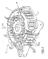
- the rear bearing 1 that appears on the figure 1 in section with the other elements of the alternator is shown only in perspective on the figure 2 .
- This bearing has a generally hollow shape of revolution, while including two protuberances 25 and 26 which extend radially relative to the skirt 18 and which form two fastening tabs on a fixed part of the vehicle.
- the discharge slots 17 each comprise an axial portion 17A extending in the axial direction of the machine, and a radial portion 17B extending in a peripheral annular zone of the front face 8 of the rear bearing 1.
- stator buns 20 which run along the internal surface of the skirt 18, in particular at the discharge slits 17.
- the cooling air current lines are represented symbolically by the arrows F, F 'and T on the figure 1 .
- the radial portions 17B of the discharge slots 17 which are provided to allow the manufacture by molding of the bearing are detrimental to cooling. Indeed, they generate on the one hand vortices T in the flow of the discharge air which introduces pressure drops, and on the other hand, the forced air F 'is sucked through the radial openings 15 and / or louvers 13 of the hood with fresh air.
- This solution is adapted to an alternator mounted in a complementary housing of the powertrain of the vehicle, the outer edge of the ring bearing against the mounting clearance close against this housing to form a watertight partition which separates the discharge slots of the gills of the cover.
- This ring is shaped to spur the shape of the corresponding housing in the engine space where the alternator is mounted.
- the object of the invention is therefore to improve the cooling of an alternator comprising a bearing such as the rear bearing described above, without modifying the design of this bearing.
- the object of the invention is also to provide a solution to improve the cooling of the alternator with additional manufacturing cost and additional space the lowest possible.
- the subject of the invention is a rotating electrical machine, such as a motor vehicle alternator, this machine including a device for forced circulation of a cooling fluid, a stator and a rotor which are housed in a housing.
- a rotating electrical machine such as a motor vehicle alternator
- this machine including a device for forced circulation of a cooling fluid, a stator and a rotor which are housed in a housing.
- a front bearing and a rear bearing at least one of the two bearings comprising a front face and a substantially cylindrical skirt, this skirt having an open end and an end closed by the front face, openings of intake of fresh air made in the front face, hot air discharge slots, each discharge slot comprising an axial portion extending in the skirt and a radial portion extending in a peripheral zone of the end face,
- the machine comprising at least one closure means which closes at least a radial portion of the slot.
- the closure means comprises at least one extension, each extension having a complementary shape of a corresponding slot radial portion to engage in a corresponding slot radial portion.
- each extension has a thickness sufficient to fill the radial slot portion that it closes over the entire thickness of this radial slot portion, so as to constitute an inner surface of the bearing which is continuous in the closed area.
- At least one extension of the closure means constitutes a lug adapted to snap into a corresponding slot radial portion to both seal this radial slot portion and ensure the fixing of the closure means to the bearing.
- the sealing means is formed by a ring fixed to the front face of the bearing.
- the machine comprises a cover covering the bearing, and the sealing means is part of the cover that extends.
- the machine comprises a plurality of closure means, each closure means forming a plug which locks in a radial slot portion snap.
- the sealing means is made of plastic.
- the closure means is fixed to the bearing by tie rods or screws.
- the invention also relates to a closure means for a rotary electrical machine, such as a motor vehicle alternator, this machine including a forced circulation device for a cooling fluid, a stator and a rotor which are housed in a housing.
- crankcase with a front bearing and a bearing rear, at least one of the two bearings comprising a front face and a substantially cylindrical skirt, this skirt having an open end and an end closed by the end face, fresh air intake openings made in the front face, hot air discharge slots, each discharge slot comprising an axial portion extending into the skirt and a radial portion extending into a peripheral zone of the end face.
- the closure means comprises at least one extension intended to plug at least one radial portion of slot each extension having a shape complementary to a radial portion of the corresponding discharge slot of the bearing to engage in a part. corresponding slot radial.
- the rotating electrical machine comprises at least one closure means 27 which minus a radial portion 17B of slot.
- the radial portions 17B of the discharge slots 17 in the front face 8 of the rear bearing 1 are plugged by a closure means 27.
- the radial portions 17B of the slots 17 do not evacuate. air, which avoids generating vortices T, and prevents hot air F to recirculate in the alternator.
- the radial portions 17B can be plugged either by a plurality of independent closure means 27 fixed to the rear bearing 1, or by a single closure means 27 possibly forming part of the cover 11 here made of plastic.
- the closure means 27 has a generally annular shape and forms part of the cover 11. It constitutes a generally flat annular surface perpendicular to the skirt 14 of the cover 11 which it extends radially at the level of the circular edge of the free end of this cylindrical wall.
- This closure means 27 comprises several extensions marked by 28 in the figures, which engage within the radial portions of corresponding slots 17B that they close.
- these extensions 28 have a sufficient thickness to fill the radial portion 17B slot they close over its entire depth.
- the extensions thus fill the radial portions of the slots 17B so as to obtain an inner surface of the rear bearing 1 which is also continuous at the parts closed by the extensions 28.
- This internal surface is thus able to direct the flow of air evacuated by the fan 16, in a direction as radial as possible to prevent this air can be sucked by the openings 13, 15, and this, introducing the least amount of air. possible pressure drop, thanks to the suppression of turbulence, more precisely of swirling air backs.
- the inner surface of the rear bearing with the parts closed by the extensions 28 is conical so as to direct the flow of air evacuated by the fan 16 towards the front of the alternator, that is to say in one direction substantially opposed to the gills 13, 15.
- the extensions 28 may advantageously have complementary shapes of the internal shape of the ends of slots 17B that they close so as to lock in it by snapping to also ensure the fixing of the closure means 27 and the cover 11 on the rear bearing 1.
- one or more extensions 28 of the closure means 27 constitute both a shutter plugging a radial portion 17B of slot 17, and a pin for fixing the closure means 27 and the cover to the rear bearing 1.
- each slot radial portion 17B can be closed by a shutter means of its own, each closure means then being a plug which locks in this radial slot portion 17B due to its complementary shape.
- the closure means 27 is formed by an independent piece that can be made of plastic, which is fixed to the rear bearing 1 by one or more screws marked by 29. These screws 29 pass through the closure means 27 which generally has a annular shape and which surrounds a circular edge of the cover 11, being screwed into corresponding threads formed in the end face 8 of the rear bearing 1.
- the closure means 27 may be fixed to the rear bearing 1 by any other appropriate means, for example by tie rods, by gluing or by attachment to another element of the alternator such as the cover 11.
- the closure means 27 comprises extensions 28 having complementary shapes of the inside of the radial portions 17B of the slots 17 to direct the flow of hot air expelled by the fan 16 in a direction inscribed in a radial plane in order to reduce as much as possible the risk of looping back this hot air and swirls.
- the invention makes it possible to improve the cooling of an alternator without having to modify the shape or the molding technique of the rear bearing 1 that it comprises.
- the sealing means 27 is advantageously made of molded plastic, so that its manufacturing cost per se is very low. It can also be realized in the form of an independent insert intended to be fixed to the rear bearing 1, so that it can be adapted to an existing rear bearing, without it being necessary to modify the rear bearing. 1, or the cover 11 of this bearing.
- the invention is applied to an alternator rear bearing, on which is mounted the recovery device 9 which is the hottest part of the alternator.
- the invention also applies to the front bearing of an alternator that does not necessarily support a recovery device, but which can nevertheless have a very similar shape, and whose cooling must also be optimal.
- the closure means may be part of a baffle having the shape of the cover 11 then lacking the bottom 17.
- the invention also applies to the case of an alternator in which one of the bearings is cooled by water, and the other by air.
- the alternator housing may have more than two parts, for example three parts, namely a front bearing, a rear bearing and an intermediate portion implanted between the two bearings and fixed thereto, for example by screwing.
- the invention also applies to rotating electrical machines generally provided with a current converter, whether it be a rectifier as in the embodiments presented above, or a device of the type chopper or inverter, which corresponds for example to the case of an alternator-starter which also applies the invention.
- a current converter whether it be a rectifier as in the embodiments presented above, or a device of the type chopper or inverter, which corresponds for example to the case of an alternator-starter which also applies the invention.
- some of the slots are provided with a closure means which closes at least a radial portion 17B of slot 17.
Description
L'invention concerne une machine électrique tournante, telle qu'un alternateur de véhicule automobile, et un moyen de cache pour une telle machine.The invention relates to a rotating electrical machine, such as a motor vehicle alternator, and a cache means for such a machine.
De telles machines électriques comprennent généralement un dispositif de circulation forcée d'un fluide de refroidissement, un stator et un rotor qui sont logés dans un carter pourvu d'un palier avant et d'un palier arrière. L'un au moins des deux paliers comprend une face frontale et une jupe sensiblement cylindrique, cette jupe ayant une extrémité ouverte et une extrémité fermée par la face frontale. Ce palier comprend des ouvertures d'admission d'air frais réalisées dans la face frontale, et des fentes de refoulement d'air chaud. Chaque fente de refoulement comprend une partie axiale s'étendant dans la jupe et une partie radiale s'étendant dans une zone périphérique de la face frontale.Such electrical machines generally comprise a device for forced circulation of a cooling fluid, a stator and a rotor which are housed in a casing provided with a front bearing and a rear bearing. At least one of the two bearings comprises a front face and a substantially cylindrical skirt, this skirt having an open end and an end closed by the front face. This bearing comprises fresh air intake openings made in the front face, and hot air discharge slots. Each discharge slot comprises an axial portion extending into the skirt and a radial portion extending into a peripheral zone of the end face.
Un tel alternateur, qui est par exemple décrit par le document
Comme visible dans cette figure, le carter de cet alternateur renferme un stator 3 entourant un rotor 4, qui est solidaire d'un axe ou arbre 5. Cet axe 5 qui s'étend selon une direction longitudinale XX de l'alternateur est supporté par un roulement à bille 7 monté dans un logement correspondant 6 qui est réalisé au centre de la face frontale 8 du palier arrière. Le stator 3 présente un corps comportant des bobinages traversant le corps que présente le stator. Les bobinages s'étendent de part et d'autre du corps du stator pour formation de chignons dont l'un est visible en 20 à la
Le palier arrière 1, supporte du côté extérieur de sa face frontale 8 plusieurs organes électroniques constituant notamment un dispositif de redressement 9. Ce dispositif de redressement 9 est ici un pont de diodes 10 qui convertit le courant alternatif produit par les bobinages du stator en un courant continu.The rear bearing 1, supports on the outer side of its
Le dispositif de redressement 9 est recouvert par un capot 3.1 comprenant un fond 12 muni d'ouïes frontales 13, et une paroi 14 latérale sensiblement cylindrique munie dans un mode de réalisation d'ouïes latérales 15. L'extrémité de la paroi cylindrique 14 qui est opposée au fond 12 définit un bord circulaire 23 qui est en appui contre la face frontale 8 du palier arrière 1.The straightening
Le refroidissement de cet alternateur est assuré par un ventilateur interne 16 situé à l'intérieur du palier arrière 1, concentriquement à la jupe 18 qui l'entoure. Ce ventilateur 16 comprend un plateau circulaire 21 accolé à une extrémité du rotor 4 ici à griffes, dont il est solidaire, ce plateau circulaire portant des pales 22 qui sont situées sensiblement au droit de la jupe 18.The cooling of this alternator is provided by an
Le ventilateur 16 aspire de l'air frais axialement à travers les ouïes 13 et 15 du capot 11 pour que cet air refroidisse le pont de diodes 10. Cet air traverse ensuite la face frontale 8 du palier arrière 1 par des ouvertures d'admission 19, pour être refoulé radialement à travers des fentes de refoulement 17, par les pales 22 du ventilateur 16.The
Le palier arrière 1 qui apparaît sur la
Les fentes de refoulement 17 comprennent chacune une partie axiale 17A s'étendant dans la direction axiale de la machine, et une partie radiale 17B s'étendant dans une zone annulaire périphérique de la face frontale 8 du palier arrière 1.The
L'air qui est évacué à travers les fentes 17 refroidit également des chignons 20 du stator qui longent la surface interne de la jupe 18 notamment au niveau des fentes de refoulement 17.The air that is evacuated through the
Les lignes de courant de l'air de refroidissement sont représentées de façon symbolique par les flèches F, F' et T sur la
Selon cette disposition, les parties radiales 17B des fentes de refoulement 17 qui sont prévues pour permettre la fabrication par moulage du palier sont préjudiciables au refroidissement. En effet, elles génèrent d'une part des tourbillons T dans l'écoulement de l'air de refoulement ce qui introduit des pertes de charge, et d'autre part, de l'air refoulé F' est aspiré à travers les ouvertures radiales 15 et/ou des ouïes 13 du capot avec de l'air frais.According to this arrangement, the
Dans le document
Dans l'alternateur qui est connu du brevet
Cette solution est adaptée à un alternateur monté dans un logement complémentaire du groupe motopropulseur du véhicule, le bord externe de l'anneau étant en appui au jeu de montage près contre ce logement pour constituer une cloison étanche qui sépare les fentes de refoulement des ouïes du capot.This solution is adapted to an alternator mounted in a complementary housing of the powertrain of the vehicle, the outer edge of the ring bearing against the mounting clearance close against this housing to form a watertight partition which separates the discharge slots of the gills of the cover.
Cet anneau est conformé pour épouseur la forme du logement correspondant dans l'espace moteur où est monté l'alternateur.This ring is shaped to spur the shape of the corresponding housing in the engine space where the alternator is mounted.
Cependant, l'augmentation des besoins électriques des véhicules automobiles conduit à des alternateurs qui doivent produire une puissance électrique de plus en plus élevée, ce qui génère une quantité de chaleur nécessitant des améliorations importantes de leur refroidissement. En même temps, les moteurs thermiques auxquels ces alternateurs sont destinés, sont de plus en plus compacts et ne permettent pas d'augmentation du volume de ces machines.However, the increase in the electrical needs of motor vehicles leads to alternators that must produce an increasingly high electrical power, which generates a quantity of heat requiring significant improvements in their cooling. At the same time, the engines for which these alternators are intended, are increasingly compact and do not allow an increase in the volume of these machines.
Le but de l'invention est donc d'améliorer le refroidissement d'un alternateur comprenant un palier tel que le palier arrière décrit ci-dessus, sans modifier la conception de ce palier.The object of the invention is therefore to improve the cooling of an alternator comprising a bearing such as the rear bearing described above, without modifying the design of this bearing.
Le but de l'invention est par ailleurs de proposer une solution pour améliorer le refroidissement de l'alternateur moyennant un surcoût de fabrication et un encombrement supplémentaire les plus faibles possibles.The object of the invention is also to provide a solution to improve the cooling of the alternator with additional manufacturing cost and additional space the lowest possible.
A cet effet, l'invention a pour objet une machine électrique tournante, telle qu'un alternateur de véhicule automobile, cette machine incluant un dispositif de circulation forcée d'un fluide de refroidissement, un stator et un rotor qui sont logés dans un carter pourvu d'un palier avant et d'un palier arrière, l'un au moins des deux paliers comprenant une face frontale et une jupe sensiblement cylindrique, cette jupe ayant une extrémité ouverte et une extrémité fermée par la face frontale, des ouvertures d'admission d'air frais réalisées dans la face frontale, des fentes de refoulement d'air chaud, chaque fente de refoulement comprenant une partie axiale s'étendant dans la jupe et une partie radiale s'étendant dans une zone périphérique de la face frontale,For this purpose, the subject of the invention is a rotating electrical machine, such as a motor vehicle alternator, this machine including a device for forced circulation of a cooling fluid, a stator and a rotor which are housed in a housing. provided with a front bearing and a rear bearing, at least one of the two bearings comprising a front face and a substantially cylindrical skirt, this skirt having an open end and an end closed by the front face, openings of intake of fresh air made in the front face, hot air discharge slots, each discharge slot comprising an axial portion extending in the skirt and a radial portion extending in a peripheral zone of the end face,
la machine comprenant au moins un moyen d'obturation qui bouche au moins une partie radiale de fente.the machine comprising at least one closure means which closes at least a radial portion of the slot.
Selon l'invention, le moyen d'obturation comprend au moins une extension, chaque extension ayant une forme complémentaire d'une partie radiale de fente correspondante pour s'engager dans une partie radiale de fente correspondante.According to the invention, the closure means comprises at least one extension, each extension having a complementary shape of a corresponding slot radial portion to engage in a corresponding slot radial portion.
Selon un mode particulier de réalisation de l'invention, chaque extension a une épaisseur suffisante pour combler la partie radiale de fente qu'il obture sur toute l'épaisseur de cette partie radiale de fente, de manière à constituer une surface interne du palier qui est continue dans la zone obturée.According to a particular embodiment of the invention, each extension has a thickness sufficient to fill the radial slot portion that it closes over the entire thickness of this radial slot portion, so as to constitute an inner surface of the bearing which is continuous in the closed area.
Avantageusement, au moins une extension du moyen d'obturation constitue un ergot apte à s'encliqueter dans une partie radiale de fente correspondante pour à la fois obturer cette partie radiale de fente et assurer la fixation du moyen d'obturation au palier.Advantageously, at least one extension of the closure means constitutes a lug adapted to snap into a corresponding slot radial portion to both seal this radial slot portion and ensure the fixing of the closure means to the bearing.
Selon un mode particulier de réalisation de l'invention, le moyen d'obturation est formé par un anneau fixé à la face frontale du palier.According to a particular embodiment of the invention, the sealing means is formed by a ring fixed to the front face of the bearing.
Selon un mode particulier de réalisation de l'invention, la machine comprend un capot recouvrant le palier, et le moyen d'obturation fait partie du capot qu'il prolonge.According to a particular embodiment of the invention, the machine comprises a cover covering the bearing, and the sealing means is part of the cover that extends.
Selon un mode particulier de réalisation de l'invention, la machine comprend plusieurs moyens d'obturation, chaque moyen d'obturation formant un bouchon qui se bloque dans une partie radiale de fente par encliquetage.According to a particular embodiment of the invention, the machine comprises a plurality of closure means, each closure means forming a plug which locks in a radial slot portion snap.
Selon un mode particulier de réalisation de l'invention, le moyen d'obturation est réalisé en matière plastique.According to a particular embodiment of the invention, the sealing means is made of plastic.
Selon un mode particulier de réalisation de l'invention, le moyen d'obturation est fixé au palier par des tirants ou par des vis.According to a particular embodiment of the invention, the closure means is fixed to the bearing by tie rods or screws.
L'invention concerne également un moyen d'obturation pour une machine électrique tournante, telle qu'un alternateur de véhicule automobile, cette machine incluant un dispositif de circulation forcée d'un fluide de refroidissement, un stator et un rotor qui sont logés dans un carter pourvu d'un palier avant et d'un palier arrière, l'un au moins des deux paliers comprenant une face frontale et une jupe sensiblement cylindrique, cette jupe ayant une extrémité ouverte et une extrémité fermée par la face frontale, des ouvertures d'admission d'air frais réalisées dans la face frontale, des fentes de refoulement d'air chaud, chaque fente de refoulement comprenant une partie axiale s'étendant dans la jupe et une partie radiale s'étendant dans une zone périphérique de la face frontale.The invention also relates to a closure means for a rotary electrical machine, such as a motor vehicle alternator, this machine including a forced circulation device for a cooling fluid, a stator and a rotor which are housed in a housing. crankcase with a front bearing and a bearing rear, at least one of the two bearings comprising a front face and a substantially cylindrical skirt, this skirt having an open end and an end closed by the end face, fresh air intake openings made in the front face, hot air discharge slots, each discharge slot comprising an axial portion extending into the skirt and a radial portion extending into a peripheral zone of the end face.
Selon l'invention, le moyen d'obturation comprend au moins une extension prévue pour boucher au moins une partie radiale de fente chaque extension ayant une forme complémentaire d'une partie radiale de fente de refoulement correspondante du palier pour s'engager dans une partie radiale de fente correspondante.According to the invention, the closure means comprises at least one extension intended to plug at least one radial portion of slot each extension having a shape complementary to a radial portion of the corresponding discharge slot of the bearing to engage in a part. corresponding slot radial.
L'invention sera maintenant décrite plus en détail, et en référence aux dessins annexés qui en illustrent une forme de réalisation à titre d'exemple non limitatif.
- La
figure 1 est une vue en coupe d'un d'alternateur de l'art antérieur ; - La
figure 2 est une vue d'ensemble en perspective d'un palier arrière d'alternateur fabriqué par moulage axial utilisé dans l'art antérieur et dans l'invention ; - La
figure 3 est une vue en coupe d'un alternateur équipé d'un premier moyen d'obturation selon l'invention ; - La
figure 4 est une vue en coupe d'un alternateur équipé d'un second moyen d'obturation selon l'invention.
- The
figure 1 is a sectional view of an alternator of the prior art; - The
figure 2 is an overall perspective view of an axially-molded alternator rear bearing used in the prior art and in the invention; - The
figure 3 is a sectional view of an alternator equipped with a first sealing means according to the invention; - The
figure 4 is a sectional view of an alternator equipped with a second closure means according to the invention.
La structure générale d'un alternateur, constituant une machine électrique tournante, ayant déjà été décrite dans la partie introductive, de façon globale, on ne décrira ci-après que les aspects qui sont directement en relation avec l'invention.The general structure of an alternator, constituting a rotating electrical machine, having already been described in the introductory part, globally, only those aspects which are directly related to the invention will be described below.
Selon l'invention, la machine électrique tournante comprend au moins un moyen d'obturation 27 qui bouche au moins une partie radiale 17B de fente. A la
Les parties radiales 17B peuvent être bouchées soit par plusieurs moyens d'obturation 27 indépendants fixés au palier arrière 1, soit par un moyen d'obturation 27 unique faisant éventuellement partie du capot 11 ici en matière plastique.The
Dans le mode de réalisation représenté sur la
Ce moyen d'obturation 27 comprend plusieurs extensions repérées par 28 sur les figures, qui s'engagent à l'intérieur des parties radiales de fentes 17B correspondantes qu'elles obturent.This closure means 27 comprises several extensions marked by 28 in the figures, which engage within the radial portions of corresponding
Avantageusement, ces extensions 28 ont une épaisseur suffisante pour combler la partie radiale 17B de fente qu'elles obturent sur toute sa profondeur. Les extensions comblent ainsi les parties radiales des fentes 17B de manière à obtenir une surface interne du palier arrière 1 qui est continue aussi au niveau des parties obturées par les extensions 28.Advantageously, these
Cette surface interne est ainsi apte à diriger le flux d'air évacué par le ventilateur 16, selon une direction la plus radiale possible pour éviter que cet air ne puisse être aspiré par les ouïes 13, 15, et ce, en introduisant le moins de perte de charge possible, grâce à la suppression des turbulences, plus précisément des refoulements d'air tourbillonnants.This internal surface is thus able to direct the flow of air evacuated by the
Avantageusement la surface interne du palier arrière avec les parties obturées par les extensions 28 est conique de manière à diriger le flux d'air évacué par le ventilateur 16 vers l'avant de l'alternateur, c'est-à-dire dans une direction sensiblement opposée aux ouïes 13, 15.Advantageously, the inner surface of the rear bearing with the parts closed by the
Les extensions 28 peuvent avantageusement avoir des formes complémentaires de la forme interne des extrémités de fentes 17B qu'elles bouchent de manière à se bloquer dans celle-ci par encliquetage pour assurer également la fixation du moyen d'obturation 27 et du capot 11 sur le palier arrière 1.The
Selon cette particularité, une ou plusieurs extension 28 du moyen d'obturation 27 constituent à la fois un obturateur bouchant une partie radiale 17B de fente 17, et un ergot de fixation du moyen d'obturation 27 et du capot au palier arrière 1.According to this feature, one or
Eventuellement, chaque partie radiale 17B de fente peut être fermée par un moyen d'obturation qui lui est propre, chaque moyen d'obturation étant alors un bouchon qui se bloque dans cette partie radiale de fente 17B grâce à sa forme complémentaire.Optionally, each
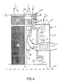
Dans le mode de réalisation représenté sur la
Le moyen d'obturation 27 peut être fixé au palier arrière 1 par tout autre moyen approprié, comme par exemple par des tirants, par collage ou encore par fixation à un autre élément de l'alternateur tel que le capot 11.The closure means 27 may be fixed to the rear bearing 1 by any other appropriate means, for example by tie rods, by gluing or by attachment to another element of the alternator such as the
De même que dans le mode de réalisation de la
Ainsi, l'invention permet d'améliorer le refroidissement d'un alternateur sans nécessiter de modifier la forme ni la technique de moulage du palier arrière 1 qu'il comprend.Thus, the invention makes it possible to improve the cooling of an alternator without having to modify the shape or the molding technique of the rear bearing 1 that it comprises.
Le moyen d'obturation 27 est avantageusement réalisé en matière plastique moulée, de sorte que son coût de fabrication en soi est très faible. Il peut de plus être réalisé sous forme d'une pièce rapportée indépendante destinée à être fixée au palier arrière 1, de sorte qu'il peut être adapté à un palier arrière existant, sans qu'il ne soit nécessaire de modifier ni le palier arrière 1, ni le capot 11 de ce palier.The sealing means 27 is advantageously made of molded plastic, so that its manufacturing cost per se is very low. It can also be realized in the form of an independent insert intended to be fixed to the rear bearing 1, so that it can be adapted to an existing rear bearing, without it being necessary to modify the rear bearing. 1, or the
Dans les modes de réalisation décrits plus haut et représentés sur les figures, l'invention est appliquée à un palier arrière d'alternateur, sur lequel est monté le dispositif de redressement 9 qui constitue la partie la plus chaude de l'alternateur.In the embodiments described above and shown in the figures, the invention is applied to an alternator rear bearing, on which is mounted the
Mais l'invention s'applique également au palier avant d'un alternateur qui ne supporte pas nécessairement de dispositif de redressement, mais qui peut néanmoins avoir une forme très similaire, et dont le refroidissement doit également être optimal. Dans ce cas, comme à la
L'invention s'applique également au cas d'un alternateur dans lequel l'un des paliers est refroidi par eau, et l'autre par air. Le carter de l'alternateur peut comporter plus de deux parties, par exemple trois parties, à savoir un palier avant, un palier arrière et une partie intermédiaire implantée entre les deux paliers et fixée à ceux-ci, par exemple par vissage.The invention also applies to the case of an alternator in which one of the bearings is cooled by water, and the other by air. The alternator housing may have more than two parts, for example three parts, namely a front bearing, a rear bearing and an intermediate portion implanted between the two bearings and fixed thereto, for example by screwing.
L'invention s'applique par ailleurs aux machines électriques tournantes pourvues de manière générale d'un convertisseur de courant, qu'il s'agisse d'un redresseur comme dans les modes de réalisation présentés plus haut, ou d'un dispositif de type hacheur ou onduleur, ce qui correspond par exemple au cas d'un alterno-démarreur auquel s'applique également l'invention. Bien entendu, en variante, certaines des fentes sont dotées d'un moyen d'obturation qui ferme au moins une partie radiale 17B de fente 17.The invention also applies to rotating electrical machines generally provided with a current converter, whether it be a rectifier as in the embodiments presented above, or a device of the type chopper or inverter, which corresponds for example to the case of an alternator-starter which also applies the invention. Of course, alternatively, some of the slots are provided with a closure means which closes at least a
On appréciera que l'encombrement radial de l'alternateur selon l'invention est réduit par rapport notamment à celui document
Claims (9)
- Electrical rotating machine, such as an alternator for a motor vehicle, this machine including a device (16) for the forced circulation of a coolant, a stator (3) and a rotor (4) which are housed in a casing provided with a front bearing and a rear bearing (1), at least one of the two bearings (1) comprising a transverse face (8) and a substantially cylindrical skirt (18), this skirt (18) having an open end and a closed end that is closed by the transverse face (8), openings (19) for the inlet of cool air, said openings being made in the transverse face (8), slots (17) for the discharge of hot air, each discharge slot comprising an axial portion (17A) extending in the skirt (18), the machine comprising a radial portion (17B) extending in a peripheral zone of the transverse face (8), and at least one closing-off means (27) which closes off at least one radial portion (17B) of slot (17), characterized in that the closing-off means (27) comprises at least one extension (28), each extension having a shape to complement a corresponding radial portion (17B) of slot (17) in order to be engaged in a corresponding radial portion (17B) of slot (17).
- Machine according to Claim 1, characterized in that each extension (28) is of sufficient thickness to fill the radial portion (17B) of slot that it encloses over the whole thickness of this radial portion (17B) of slot, so as to constitute an internal surface of the bearing (1) that is continuous in the zone that is closed off.
- Machine according to Claim 1 or 2, characterized in that at least one extension (28) of the closing-off means constitutes a lug capable of snap-fitting into a corresponding radial portion (17B) of slot (17) in order at the same time to close off this radial portion (17B) of slot and fasten the closing-off means (27) to the bearing (1).
- Machine according to any one of the preceding claims, characterized in that the closing-off means (27) is formed by a ring fixed to the transverse face (8) of the bearing (1).
- Machine according to any one of the preceding claims, comprising a cap (11) covering the bearing (1), characterized in that the closing-off means (27) forms part of the cap (11) that it extends.
- Machine according to any one of the preceding claims, characterized in that it comprises several closing-off means (27), each closing-off means forming a plug which is immobilized in a radial portion (17B) of slot by snap-fitting.
- Machine according to any one of the preceding claims, characterized in that the closing-off means (27) is made of plastic.
- Machine according to any one of the preceding claims, characterized in that the closing-off means (27) is fixed to the bearing (1) by tie-rods or by screws (29).
- Closing-off means for an electrical rotating machine, such as an alternator for a motor vehicle, this machine including a device (16) for the forced circulation of a coolant, a stator (3) and a rotor (4) which are housed in a casing provided with a front bearing and a rear bearing (1), at least one of the two bearings (1) comprising a transverse face (8) and a substantially cylindrical skirt (18), this skirt (18) having an open end and a closed end that is closed by the transverse face (8), openings (19) for the inlet of cool air, said openings being made in the transverse face (8), slots (17) for the discharge of hot air, each discharge slot comprising an axial portion (17A) extending in the skirt (18) and a radial portion (17B) extending in a peripheral zone of the transverse face (8), characterized in that it comprises at least one extension (28) designed to plug at least one radial portion (17B) of slot (17), each extension having a shape to complement a corresponding radial portion (17B) of slot (17) in order to be engaged in a corresponding radial portion (17B) of slot (17).
Applications Claiming Priority (2)
| Application Number | Priority Date | Filing Date | Title |
|---|---|---|---|
| FR0404662A FR2870054B1 (en) | 2004-04-30 | 2004-04-30 | AIR-REFRIGERATED ALTERNATOR COMPRISING A CLOSING MEANS CLOSING OUTLETS OF COOLING AIR DELIVERY SLOTS |
| PCT/FR2005/001039 WO2005117241A1 (en) | 2004-04-30 | 2005-04-27 | Alternator for a motor vehicle |
Publications (2)
| Publication Number | Publication Date |
|---|---|
| EP1741176A1 EP1741176A1 (en) | 2007-01-10 |
| EP1741176B1 true EP1741176B1 (en) | 2013-04-03 |
Family
ID=34944687
Family Applications (1)
| Application Number | Title | Priority Date | Filing Date |
|---|---|---|---|
| EP05767468A Active EP1741176B1 (en) | 2004-04-30 | 2005-04-27 | Alternator for a motor vehicle |
Country Status (5)
| Country | Link |
|---|---|
| EP (1) | EP1741176B1 (en) |
| JP (1) | JP4755177B2 (en) |
| CN (1) | CN1930759B (en) |
| FR (1) | FR2870054B1 (en) |
| WO (1) | WO2005117241A1 (en) |
Families Citing this family (6)
| Publication number | Priority date | Publication date | Assignee | Title |
|---|---|---|---|---|
| FR2998732B1 (en) * | 2012-11-28 | 2015-01-02 | Valeo Equip Electr Moteur | HOOD FOR A ROTATING ELECTRICAL MACHINE FOR COVERING A FRONT PANEL |
| CN105703540B (en) * | 2014-11-24 | 2020-09-01 | 舍弗勒技术有限两合公司 | Liquid cooling type in-wheel motor and motor vehicle |
| FR3062531B1 (en) * | 2017-01-27 | 2019-06-07 | Valeo Equipements Electriques Moteur | ROTATING ELECTRIC MACHINE WITH SHUTTER LIMITING HOT AIR REBOUCLING |
| FR3066658B1 (en) * | 2017-05-18 | 2020-01-10 | Valeo Equipements Electriques Moteur | ROTATING ELECTRIC MACHINE HAVING A BEARING HAVING AT LEAST ONE CLAMPING PORTION |
| CN111052566B (en) * | 2017-09-29 | 2022-05-27 | 日本电产株式会社 | Motor |
| FR3079979B1 (en) * | 2018-04-10 | 2020-03-06 | Valeo Equipements Electriques Moteur | ROTATING ELECTRICAL MACHINE WITH IMPROVED COOLING |
Family Cites Families (4)
| Publication number | Priority date | Publication date | Assignee | Title |
|---|---|---|---|---|
| JP3514319B2 (en) * | 1993-07-26 | 2004-03-31 | 株式会社デンソー | Rotating electric machine |
| FR2733642B1 (en) | 1995-04-26 | 1997-06-06 | Valeo Equip Electr Moteur | ALTERNATOR FOR A MOTOR VEHICLE PROVIDED WITH EXTERNAL PARTITIONING MEANS TO AVOID A BLOCKING OF THE COOLING AIR CIRCUIT |
| WO1999041822A1 (en) * | 1998-02-13 | 1999-08-19 | Hitachi, Ltd. | Open type electric motor for driving vehicle |
| JP3842001B2 (en) * | 2000-02-16 | 2006-11-08 | 三菱電機株式会社 | AC generator for vehicles |
-
2004
- 2004-04-30 FR FR0404662A patent/FR2870054B1/en not_active Expired - Fee Related
-
2005
- 2005-04-27 JP JP2007510075A patent/JP4755177B2/en not_active Expired - Fee Related
- 2005-04-27 EP EP05767468A patent/EP1741176B1/en active Active
- 2005-04-27 CN CN2005800070465A patent/CN1930759B/en active Active
- 2005-04-27 WO PCT/FR2005/001039 patent/WO2005117241A1/en not_active Application Discontinuation
Also Published As
| Publication number | Publication date |
|---|---|
| WO2005117241A1 (en) | 2005-12-08 |
| EP1741176A1 (en) | 2007-01-10 |
| FR2870054A1 (en) | 2005-11-11 |
| FR2870054B1 (en) | 2006-07-21 |
| CN1930759A (en) | 2007-03-14 |
| CN1930759B (en) | 2011-03-30 |
| JP4755177B2 (en) | 2011-08-24 |
| JP2007535889A (en) | 2007-12-06 |
Similar Documents
| Publication | Publication Date | Title |
|---|---|---|
| FR2765042A1 (en) | ALTERNATOR WITH IMPROVED COOLING MEANS, IN PARTICULAR FOR A MOTOR VEHICLE | |
| EP1741176B1 (en) | Alternator for a motor vehicle | |
| FR3013531A1 (en) | ROTATING ELECTRICAL MACHINE HOUSING ASSEMBLY AND ROTATING ELECTRICAL MACHINE COMPRISING SUCH AN ASSEMBLY | |
| FR2824201A1 (en) | VENTILATION DEVICE FOR ROTATING ELECTRIC MACHINE | |
| FR2742606A1 (en) | Car engine alternator with water cooling circuit | |
| FR2853365A1 (en) | VENTILATION DEVICE | |
| WO2019025334A1 (en) | Electrical rotating machine comprising a liquid deflector | |
| FR2811156A1 (en) | Fan for a rotating electrical machine, particularly an alternator fitted to a motor vehicle, uses supplementary blades between outer regions of principal blades to provide better air flow | |
| FR2998732A1 (en) | Cap for covering front face of revolving electric machine e.g. alternator, of car, has articulated obturation unit for closing radial portion of coolant discharge slot, where obturation unit is positioned above radial portion of slot | |
| FR3064540B1 (en) | SUPPORT FOR VENTILATION DEVICE, VENTILATION DEVICE AND CORRESPONDING COOLING MODULE | |
| FR2740274A1 (en) | ALTERNATOR HAVING IMPROVED INTERNAL VENTILATION MEANS | |
| FR2780572A1 (en) | ALTERNATOR FOR VEHICLE WITH LIQUID CRANKCASE COOLING CIRCUIT | |
| FR3075506B1 (en) | ASSEMBLY COMPRISING A ROTATING ELECTRIC MACHINE CASE | |
| WO2021180489A1 (en) | Plastic flange with reinforcing rim for a rotating electrical machine | |
| FR3132809A1 (en) | Rotor for a rotating electric machine | |
| FR3077344A1 (en) | FAN PROPELLER FOR MOTOR VEHICLE | |
| WO2022200382A1 (en) | Cooling module for an electric or hybrid motor vehicle, having a tangential-flow turbomachine | |
| FR3089364A1 (en) | Rotating electric machine comprising a cooling device | |
| FR2858884A1 (en) | DISPOSSIVE COOLING OF AN ALTERNATOR WITH AIR GUIDE | |
| EP3991276A1 (en) | Housing for a rotating electric machine, comprising a plastic bearing | |
| EP4204669A1 (en) | Cooling module for an electric motor vehicle, comprising a tangential-flow turbomachine | |
| FR3038793A1 (en) | ROTATING ELECTRIC MACHINE WITH LUBRICANT TANK FOR LUBRICATION OF BEARING | |
| WO2020161154A1 (en) | Sealing device between a clutch basket and a rotating electrical machine | |
| FR3093764A1 (en) | TANGENTIAL TURBOMACHINE ELECTRIC MOTOR VEHICLE COOLING MODULE | |
| FR2864368A1 (en) | Electrical machine e.g. alternator, ventilation reinforcing device for motor vehicle, has set of ventilators with blades and arranged between pulley and another set of ventilators for charging latter set of ventilators |
Legal Events
| Date | Code | Title | Description |
|---|---|---|---|
| PUAI | Public reference made under article 153(3) epc to a published international application that has entered the european phase |
Free format text: ORIGINAL CODE: 0009012 |
|
| 17P | Request for examination filed |
Effective date: 20061018 |
|
| AK | Designated contracting states |
Kind code of ref document: A1 Designated state(s): AT BE BG CH CY CZ DE DK EE ES FI FR GB GR HU IE IS IT LI LT LU MC NL PL PT RO SE SI SK TR |
|
| DAX | Request for extension of the european patent (deleted) | ||
| 17Q | First examination report despatched |
Effective date: 20090330 |
|
| GRAP | Despatch of communication of intention to grant a patent |
Free format text: ORIGINAL CODE: EPIDOSNIGR1 |
|
| GRAS | Grant fee paid |
Free format text: ORIGINAL CODE: EPIDOSNIGR3 |
|
| GRAA | (expected) grant |
Free format text: ORIGINAL CODE: 0009210 |
|
| AK | Designated contracting states |
Kind code of ref document: B1 Designated state(s): AT BE BG CH CY CZ DE DK EE ES FI FR GB GR HU IE IS IT LI LT LU MC NL PL PT RO SE SI SK TR |
|
| REG | Reference to a national code |
Ref country code: GB Ref legal event code: FG4D Free format text: NOT ENGLISH |
|
| REG | Reference to a national code |
Ref country code: CH Ref legal event code: EP Ref country code: AT Ref legal event code: REF Ref document number: 605249 Country of ref document: AT Kind code of ref document: T Effective date: 20130415 |
|
| REG | Reference to a national code |
Ref country code: IE Ref legal event code: FG4D Free format text: LANGUAGE OF EP DOCUMENT: FRENCH |
|
| REG | Reference to a national code |
Ref country code: DE Ref legal event code: R096 Ref document number: 602005038895 Country of ref document: DE Effective date: 20130606 |
|
| REG | Reference to a national code |
Ref country code: AT Ref legal event code: MK05 Ref document number: 605249 Country of ref document: AT Kind code of ref document: T Effective date: 20130403 |
|
| PG25 | Lapsed in a contracting state [announced via postgrant information from national office to epo] |
Ref country code: SI Free format text: LAPSE BECAUSE OF FAILURE TO SUBMIT A TRANSLATION OF THE DESCRIPTION OR TO PAY THE FEE WITHIN THE PRESCRIBED TIME-LIMIT Effective date: 20130403 |
|
| REG | Reference to a national code |
Ref country code: NL Ref legal event code: VDEP Effective date: 20130403 |
|
| REG | Reference to a national code |
Ref country code: LT Ref legal event code: MG4D |
|
| BERE | Be: lapsed |
Owner name: VALEO EQUIPEMENTS ELECTRIQUES MOTEUR Effective date: 20130430 |
|
| PG25 | Lapsed in a contracting state [announced via postgrant information from national office to epo] |
Ref country code: FI Free format text: LAPSE BECAUSE OF FAILURE TO SUBMIT A TRANSLATION OF THE DESCRIPTION OR TO PAY THE FEE WITHIN THE PRESCRIBED TIME-LIMIT Effective date: 20130403 Ref country code: IS Free format text: LAPSE BECAUSE OF FAILURE TO SUBMIT A TRANSLATION OF THE DESCRIPTION OR TO PAY THE FEE WITHIN THE PRESCRIBED TIME-LIMIT Effective date: 20130803 Ref country code: SE Free format text: LAPSE BECAUSE OF FAILURE TO SUBMIT A TRANSLATION OF THE DESCRIPTION OR TO PAY THE FEE WITHIN THE PRESCRIBED TIME-LIMIT Effective date: 20130403 Ref country code: AT Free format text: LAPSE BECAUSE OF FAILURE TO SUBMIT A TRANSLATION OF THE DESCRIPTION OR TO PAY THE FEE WITHIN THE PRESCRIBED TIME-LIMIT Effective date: 20130403 Ref country code: GR Free format text: LAPSE BECAUSE OF FAILURE TO SUBMIT A TRANSLATION OF THE DESCRIPTION OR TO PAY THE FEE WITHIN THE PRESCRIBED TIME-LIMIT Effective date: 20130704 Ref country code: PT Free format text: LAPSE BECAUSE OF FAILURE TO SUBMIT A TRANSLATION OF THE DESCRIPTION OR TO PAY THE FEE WITHIN THE PRESCRIBED TIME-LIMIT Effective date: 20130805 Ref country code: LT Free format text: LAPSE BECAUSE OF FAILURE TO SUBMIT A TRANSLATION OF THE DESCRIPTION OR TO PAY THE FEE WITHIN THE PRESCRIBED TIME-LIMIT Effective date: 20130403 Ref country code: NL Free format text: LAPSE BECAUSE OF FAILURE TO SUBMIT A TRANSLATION OF THE DESCRIPTION OR TO PAY THE FEE WITHIN THE PRESCRIBED TIME-LIMIT Effective date: 20130403 Ref country code: ES Free format text: LAPSE BECAUSE OF FAILURE TO SUBMIT A TRANSLATION OF THE DESCRIPTION OR TO PAY THE FEE WITHIN THE PRESCRIBED TIME-LIMIT Effective date: 20130714 |
|
| PG25 | Lapsed in a contracting state [announced via postgrant information from national office to epo] |
Ref country code: PL Free format text: LAPSE BECAUSE OF FAILURE TO SUBMIT A TRANSLATION OF THE DESCRIPTION OR TO PAY THE FEE WITHIN THE PRESCRIBED TIME-LIMIT Effective date: 20130403 Ref country code: BG Free format text: LAPSE BECAUSE OF FAILURE TO SUBMIT A TRANSLATION OF THE DESCRIPTION OR TO PAY THE FEE WITHIN THE PRESCRIBED TIME-LIMIT Effective date: 20130703 Ref country code: CY Free format text: LAPSE BECAUSE OF FAILURE TO SUBMIT A TRANSLATION OF THE DESCRIPTION OR TO PAY THE FEE WITHIN THE PRESCRIBED TIME-LIMIT Effective date: 20130403 |
|
| REG | Reference to a national code |
Ref country code: CH Ref legal event code: PL |
|
| REG | Reference to a national code |
Ref country code: IE Ref legal event code: MM4A |
|
| PG25 | Lapsed in a contracting state [announced via postgrant information from national office to epo] |
Ref country code: EE Free format text: LAPSE BECAUSE OF FAILURE TO SUBMIT A TRANSLATION OF THE DESCRIPTION OR TO PAY THE FEE WITHIN THE PRESCRIBED TIME-LIMIT Effective date: 20130403 Ref country code: MC Free format text: LAPSE BECAUSE OF FAILURE TO SUBMIT A TRANSLATION OF THE DESCRIPTION OR TO PAY THE FEE WITHIN THE PRESCRIBED TIME-LIMIT Effective date: 20130403 Ref country code: CH Free format text: LAPSE BECAUSE OF NON-PAYMENT OF DUE FEES Effective date: 20130430 Ref country code: LI Free format text: LAPSE BECAUSE OF NON-PAYMENT OF DUE FEES Effective date: 20130430 Ref country code: DK Free format text: LAPSE BECAUSE OF FAILURE TO SUBMIT A TRANSLATION OF THE DESCRIPTION OR TO PAY THE FEE WITHIN THE PRESCRIBED TIME-LIMIT Effective date: 20130403 Ref country code: CZ Free format text: LAPSE BECAUSE OF FAILURE TO SUBMIT A TRANSLATION OF THE DESCRIPTION OR TO PAY THE FEE WITHIN THE PRESCRIBED TIME-LIMIT Effective date: 20130403 Ref country code: BE Free format text: LAPSE BECAUSE OF NON-PAYMENT OF DUE FEES Effective date: 20130430 Ref country code: SK Free format text: LAPSE BECAUSE OF FAILURE TO SUBMIT A TRANSLATION OF THE DESCRIPTION OR TO PAY THE FEE WITHIN THE PRESCRIBED TIME-LIMIT Effective date: 20130403 |
|
| PLBE | No opposition filed within time limit |
Free format text: ORIGINAL CODE: 0009261 |
|
| STAA | Information on the status of an ep patent application or granted ep patent |
Free format text: STATUS: NO OPPOSITION FILED WITHIN TIME LIMIT |
|
| PG25 | Lapsed in a contracting state [announced via postgrant information from national office to epo] |
Ref country code: RO Free format text: LAPSE BECAUSE OF FAILURE TO SUBMIT A TRANSLATION OF THE DESCRIPTION OR TO PAY THE FEE WITHIN THE PRESCRIBED TIME-LIMIT Effective date: 20130403 Ref country code: IT Free format text: LAPSE BECAUSE OF FAILURE TO SUBMIT A TRANSLATION OF THE DESCRIPTION OR TO PAY THE FEE WITHIN THE PRESCRIBED TIME-LIMIT Effective date: 20130403 |
|
| 26N | No opposition filed |
Effective date: 20140106 |
|
| GBPC | Gb: european patent ceased through non-payment of renewal fee |
Effective date: 20130703 |
|
| REG | Reference to a national code |
Ref country code: DE Ref legal event code: R097 Ref document number: 602005038895 Country of ref document: DE Effective date: 20140106 |
|
| PG25 | Lapsed in a contracting state [announced via postgrant information from national office to epo] |
Ref country code: IE Free format text: LAPSE BECAUSE OF NON-PAYMENT OF DUE FEES Effective date: 20130427 Ref country code: GB Free format text: LAPSE BECAUSE OF NON-PAYMENT OF DUE FEES Effective date: 20130703 |
|
| PG25 | Lapsed in a contracting state [announced via postgrant information from national office to epo] |
Ref country code: TR Free format text: LAPSE BECAUSE OF FAILURE TO SUBMIT A TRANSLATION OF THE DESCRIPTION OR TO PAY THE FEE WITHIN THE PRESCRIBED TIME-LIMIT Effective date: 20130403 |
|
| PG25 | Lapsed in a contracting state [announced via postgrant information from national office to epo] |
Ref country code: HU Free format text: LAPSE BECAUSE OF FAILURE TO SUBMIT A TRANSLATION OF THE DESCRIPTION OR TO PAY THE FEE WITHIN THE PRESCRIBED TIME-LIMIT; INVALID AB INITIO Effective date: 20050427 Ref country code: LU Free format text: LAPSE BECAUSE OF NON-PAYMENT OF DUE FEES Effective date: 20130427 |
|
| REG | Reference to a national code |
Ref country code: FR Ref legal event code: PLFP Year of fee payment: 12 |
|
| REG | Reference to a national code |
Ref country code: FR Ref legal event code: PLFP Year of fee payment: 13 |
|
| REG | Reference to a national code |
Ref country code: FR Ref legal event code: PLFP Year of fee payment: 14 |
|
| P01 | Opt-out of the competence of the unified patent court (upc) registered |
Effective date: 20230528 |
|
| PGFP | Annual fee paid to national office [announced via postgrant information from national office to epo] |
Ref country code: FR Payment date: 20230425 Year of fee payment: 19 Ref country code: DE Payment date: 20230412 Year of fee payment: 19 |