EP1740964B1 - Verfahren und vorrichtung zur charakterisierung eines dreiphasigen wandlers durch eine einphasige stromversorgung - Google Patents
Verfahren und vorrichtung zur charakterisierung eines dreiphasigen wandlers durch eine einphasige stromversorgung Download PDFInfo
- Publication number
- EP1740964B1 EP1740964B1 EP05717888.1A EP05717888A EP1740964B1 EP 1740964 B1 EP1740964 B1 EP 1740964B1 EP 05717888 A EP05717888 A EP 05717888A EP 1740964 B1 EP1740964 B1 EP 1740964B1
- Authority
- EP
- European Patent Office
- Prior art keywords
- transformer
- phase
- value
- primary
- power supply
- Prior art date
- Legal status (The legal status is an assumption and is not a legal conclusion. Google has not performed a legal analysis and makes no representation as to the accuracy of the status listed.)
- Expired - Lifetime
Links
Images


Classifications
-
- G—PHYSICS
- G01—MEASURING; TESTING
- G01R—MEASURING ELECTRIC VARIABLES; MEASURING MAGNETIC VARIABLES
- G01R29/00—Arrangements for measuring or indicating electric quantities not covered by groups G01R19/00 - G01R27/00
- G01R29/20—Measuring number of turns; Measuring transformation ratio or coupling factor of windings
-
- G—PHYSICS
- G01—MEASURING; TESTING
- G01R—MEASURING ELECTRIC VARIABLES; MEASURING MAGNETIC VARIABLES
- G01R31/00—Arrangements for testing electric properties; Arrangements for locating electric faults; Arrangements for electrical testing characterised by what is being tested not provided for elsewhere
- G01R31/50—Testing of electric apparatus, lines, cables or components for short-circuits, continuity, leakage current or incorrect line connections
- G01R31/62—Testing of transformers
-
- G—PHYSICS
- G01—MEASURING; TESTING
- G01R—MEASURING ELECTRIC VARIABLES; MEASURING MAGNETIC VARIABLES
- G01R31/00—Arrangements for testing electric properties; Arrangements for locating electric faults; Arrangements for electrical testing characterised by what is being tested not provided for elsewhere
- G01R31/28—Testing of electronic circuits, e.g. by signal tracer
- G01R31/2832—Specific tests of electronic circuits not provided for elsewhere
- G01R31/2836—Fault-finding or characterising
- G01R31/2837—Characterising or performance testing, e.g. of frequency response
-
- G—PHYSICS
- G01—MEASURING; TESTING
- G01R—MEASURING ELECTRIC VARIABLES; MEASURING MAGNETIC VARIABLES
- G01R31/00—Arrangements for testing electric properties; Arrangements for locating electric faults; Arrangements for electrical testing characterised by what is being tested not provided for elsewhere
- G01R31/50—Testing of electric apparatus, lines, cables or components for short-circuits, continuity, leakage current or incorrect line connections
- G01R31/72—Testing of electric windings
Definitions
- the present invention relates to a method and apparatus for characterising a three phase transformer using a single phase power supply.
- Three phase transformers are widely used in power supply and other applications. They typically comprise primary and secondary windings for each phase mounted on a three legged core.
- the turns ratio of a transformer is the ratio of the number of turns of its primary winding divided by the number of turns of the secondary winding, for each leg of the transformer.
- the turns ratio is equivalent to the step up or step down voltage ratio of the transformer.
- Transformers are routinely tested in this way throughout their life. Typically testing is carried out after manufacture to ensure that the transformer has been correctly wound, similarly after refurbishment or remanufacture, and as part of ongoing maintenance in order to detect any degradation in performance.
- a drawback with use of a single phase supply to measure the turns ratio of a three phase transformer is that the way voltage should be applied to the transformer and the way it should be measured depends on characteristics of the transformer being tested, particularly its configuration and phase displacement, if any
- the primary and secondary windings of a three phase transformer can each be connected in one of five known configurations D (Delta), Y (Wye), Yn, Z (Zig Zag) and Zn.
- D configuration three windings are connected end to end in a loop and three external connections for the transformer are taken from between the windings.
- Y configuration also known as star configuration
- one end of each winding are all connected together.
- the free ends of each winding form three external connections.
- Z configuration is electrically the same as Y, but each winding is distributed across more than one leg of the transformer to improve performance in the presence of an unbalanced load.
- Zn is a Z configuration with the connection between the windings brought out as neutral.
- a three phase transformer can have a phase displacement. Shifting the secondary connections with respect to the primary connections, essentially relabelling the connections, introduces a phase shift in 60 degree steps, as can reversing the windings. Configuration of the windings also affects phase. If configurations of the primary and second side are dissimilar an additional 30 degree shift is introduced. Phase displacement is usually classified using a number between 0 and 11 to indicate the number of 30 degree steps from in phase introduced by the transformer.
- a known apparatus for measuring the turns ratio of a three phase transformer is that marketed under the name Biddle TTR by AVO International, and disclosed in its publication BULLETIN-1 3PHASETTR published in 1999 .
- This apparatus measures the turns ratio of a transformer by applying a test according to IEEE STD C57.12.90-1999 - IEEE Standard Test Code for Liquid-Immersed Distribution, Power and Regulating Transformers, 30 December 1999 ISBN: 0-7381-1789-7 .
- This test does not involve applying a voltage between all available pairs of terminals of the transformer, and does not determine the winding configuration of the transformer.
- US 4,241,306 discloses a terminal switching unit intended for use with an earlier Biddle TTR apparatus. It enables four terminals of a tester to be selectively connected to seven terminals of a transformer under test.
- US 5276402A discloses a method and system for testing three phase transformers according to the ANSI C57 standard. Application of this test requires prior knowledge of the winding configuration of the transformer.
- a method of characterising a three phase transformer having three input terminals connected to each other by primary windings and three output terminals connected to each other by secondary windings, the primary and secondary windings forming a winding configuration, the method using a single phase power supply and comprising the steps of:
- the method and apparatus enable a three phase transformer to be characterised according to its winding configuration.
- the method and apparatus may classify a three phase transformer as either D-D equivalent, D-Y equivalent, Y-D equivalent or Y-Y equivalent.
- the method and apparatus may further classify a transformer according to the presence of a neutral on either the primary or secondary side of the transformer, thereby to further characterise its winding configuration.
- the method and apparatus also preferably enables the phase displacement of a transformer to be characterised.
- the apparatus comprises a single phase power supply and means for selectively applying power from the power supply to pairs of input terminals of a three phase transformer.
- Said means may comprise a switching matrix.
- the apparatus further comprises means for measuring voltage between pairs of output terminals of a three phase transformer, which means may also include a switching matrix.
- the apparatus may further include a phase meter.
- the various components of the apparatus are under the control of a control means which may comprise a programmed computer.
- the control means includes a processing means for processing measured voltages in order to determine characteristics of the transformer.
- the apparatus may further include means for shorting any two terminals of a transformer together. Such means may comprise a shorting matrix.
- the apparatus is preferably arranged to automatically characterise a transformer and provide results to a user.
- the apparatus may be further arranged to automatically test the turns ratio of a transformer using the single phase power supply, by the application of a known method.
- the apparatus is preferably self contained and portable to facilitate in the field testing of transformers.
- the power supply of the apparatus may be provided by a local mains power supply.
- Energising a transformer input to input on the primary side and measuring the output to output voltages obtained on the secondary side allows a discrimination of the transformer's class to be made.
- the transformer is energised H1-H3, H2-H1 and H3-H2 and with each energisation the line-to-line voltages X1-X3, X2-X1 and X3-X2 are measured.
- Each set of three secondary measurements is normalised to the highest line-to-line voltage measured for that energisation.
- the class of the transformer it is necessary to determine if it has neutral connections. If there is no neutral connection, there is essentially a floating connection.
- the presence of a primary neutral can be determined by comparing the voltage produced on the secondary measuring output to output when the primary is energised input to input and input to neutral. If there is a significant difference recorded it indicates that the neutral line is floating (i.e. not connected).
- a similar process can be followed to determine the presence of a neutral on the secondary side. The transformer is energised input to input on the primary and the output to output and output to neutral voltages on the secondary are compared. Again if there is a significant difference, it indicates that the neutral line is floating (i.e. not connected).
- Transformer Prim. Neut. Sec Neut. Type Group 1 No No D-D (or D-Z or Z-D or Z-Z) No Yes D-Zn Yes No Zn-D (or Zn-Z) Yes Yes Zn-Zn Group 2 No No D-Y (or Z-Y) No Yes D-Yn (or Z-.Yn) Yes No Zn-Y Yes Yes Zn-Yn Group 3 No No Y-D (or Y-Z) No Yes Y-Zn Yes No Yn-D (or Yn-Z) Yes Yes Yn-Zn Group 4 No No Y-Y No Yes Y-Yn Yes No Yn-Y Yes Yes Yn-Yn-Yn
- a three phase transformer core can be considered as having three legs A, B and C, each of which carries a primary and a secondary winding. If we regard the input to each primary winding as H1, H2 and H3 and the output of each secondary winding as X1, X2 and X3 the phase displacement is determined by which secondary outputs are on the same leg as which primary inputs. At this stage it can also be helpful to determine if any output terminals are swapped over with respect to the input terminals (e.g. X2 and X3 exchanged with respect to H2 and H3).
- Phase shift Class 1 transformers have similar primary and secondary windings (i.e. Group 1 or Group 4 transformers) while Phase shift Class 2 transformers have dissimilar primary and secondary windings. This affects the way the transformer is treated to determine the winding configuration:
- leg a X1-X3
- leg b X2-X1
- leg a' X2-X1
- leg b' X3-X2
- leg c' X1-X3 A" as energisation H3-H2
- leg a" X3-X2
- leg b" X1-X3
- leg c" X2-X1
- phase shift Once the phase shift has been determined, it is necessary to check for phase reversal, where the polarity of the secondary winding is reversed with respect to the primary winding, introducing a 180 degree phase shift onto the output. This is achieved by energising one leg of the transformer and looking at the corresponding secondary to see if the voltage is in phase with the energising voltage or 180 degrees out of phase.
- the phases to be energised and measured depend on the shift as determined previously: Determined Shift Energise Measure 0 H1-H3 X1-X3 4 H1-H3 X3-X2 8 H1-H3 X2-X1 0 (Swapped Output) H1-H3 X1-X2 4 (Swapped Output) H1-H3 X2-X3 8 (Swapped Output) H1-H3 X3-X1
- a figure from 0 to 11 for the phase displacement of the transformer is then calculated by taking the phase shift, if the windings are reversed adding 6 and if the transformer is Class 2 adding 1. If the result is greater than 11, 12 is subtracted.
- Figure 1 shows apparatus for automatically implementing the above method.
- the apparatus comprises various electrical components and provides eight electrical test connections for connection to the terminals of a transformer to be tested 3.
- the apparatus comprises an energisation source 1 which provides a single phase electrical signal to a switching matrix 2.
- a switching matrix 2 is connected to each of the four test connections for connection to terminals H0-3 of a transformer under test 3.
- a second switching matrix 6 is also connected to each of the four connections and a shorting matrix 4 is connected to the connections intended for terminals H1-3 of a transformer under test 3.
- a third switching matrix 7 is connected to each of the four connections for connection to terminals X0-3 of a transformer under test 3 and a second shorting matrix 7 is connected the connections intended for terminals X1-3 of a transformer under test 3.
- the second 6 and third 7 switching matrices are connected via respective 3 rd harmonic filters 8, 9 to respective voltmeters 10, 11 and a single phasemeter 12
- control unit 13 The various electrical components of the apparatus described above are all under control of a control unit 13.
- the energisation source 1 comprises a single-phase transformer driven from the local mains electricity supply. However, alternative generation methods can be utilised. It is important that the energisation source provides a substantially sinusoidal signal as the presence of harmonics will disrupt measurement of the turns-ratio and compromise the accuracy of the system.
- the first switching matrix 2 allows the output of the energisation source 1 to be applied, under the control of the control unit 13, across any two of the inputs H0-3 of the transformer under test 3.
- the shorting matrix 4 is, in use, connected to H1, H2 and H3 of the transformer under test 3 and allows the apparatus to short any two of the primary terminals H1-3 together. This is required for phase displacement determination.
- the second shorting matrix 5 allows any two of the secondary phase terminals X1, X2 and X3 of the transformer under test 3 to be shorted together. This feature is not utilised for the winding configuration and phase determination procedure, but is essential for subsequent turns-ratio measurement.
- the second switching matrix 6 is operative to connect any of the primary connections of the transformer under test 3, H0-3 to the voltmeter 10 and phasemeter 12. It is operated in synchronisation with the switching matrix 2 by the control means 13 so that the primary voltage at the terminals of the transformer is measured while compensating for voltage drops in the measurement cables.
- the third switching matrix 7 is operative to connect any two of the secondary terminals of the transformer under test 3, X0-3 to the voltmeter 11 and phasemeter 12.
- the third switching matrix 7 is operated by the control means 13 independently of the first and second switching matrices 2,6.
- the two 3 rd harmonic filters 8 provide a notch response with a minimum at either 150Hz or 180Hz depending on the line frequency selected. They eliminate a third harmonic generated by the energisation source 1, or a transformer under test 3, that could otherwise affect measurement.
- Voltages at the primary side of a transformer under test are measured by voltmeter 10 by measuring the peak-to-peak excursion of the primary waveform.
- the waveform is constantly sampled by an ADC (analogue to digital converter), and a digital peak detection system which returns the maximum and the minimum voltage recorded by the ADC. The difference between the two is used as a measure of the voltage. This automatically compensates for any DC offset on the measurement channel.
- Voltages at the secondary side of a transformer under test are measured by voltmeter 11 using the same technique.
- the period of the voltage measured by voltmeter 10, the primary voltage, and the time displacement between primary voltage zero crossings and zero crossings of the voltage measured by voltmeter 11 (the secondary voltage) are measured by the phasemeter 12, to determine the phase relationship between the primary and secondary voltage to be measured by the apparatus.
- the control means 13 comprises a software controlled computer, for example a PC, and is operative to control the various components of the apparatus in order to determine the configuration and phase displacement of a transformer under test 3.
- the control means 13 includes a processing means and a memory operative to store values relating to measured voltages, constants and to perform calculations and output results to a user in order to implement the algorithms described below. Any other appropriate type of control means could of course be employed.
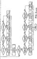
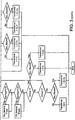
- the software is first arranged to cause the apparatus to characterise the configuration of the transformer under test by employing an algorithm illustrated in figure 2 , and then to further characterise the winding configuration and determine the phase displacement by employing the algorithm illustrated in figure 3 .
- the first stage is energising the transformer input to input in each of the possible configurations (H1-H3, H2-H1 and H3-H2) and measuring the output to output voltages in each configuration (X1-X3, X2-X1, X3-X2). For each phase energisation, three measurements result, which must be classified to establish the configuration.
- control means is arranged to compare values using magnitudes in order to allocate the figure to the appropriate class.
- the configuration of the transformer is determined.
- the group of the transformer is determined by summing the result values for each class result.
- the transformer is energised using H1-H3, and X1-X3, X2-X1 and X3-X2, are measured. The highest value is saved as X pp .
- the transformer is then energised using H1-H3 and X1-X0, X2-X0 and X3-X0 are measured. The highest value is saved as X pn .
- the transformer is finally energised using H1-H0 and X1-X3, X2-X1 and X3-X2 are measured. The highest value is saved as X np .
- Transformer Prim . Sec Type Neut . Neut.
- the final stage of the process is to determine the phase displacement of the transformer.
- the algorithm for this is also illustrated in the flow chart in figure 2 . As discussed above, there are three stages to determining the phase displacement of the transformer. If the transformer has dissimilar windings an intrinsic 30-degree phase shift introduced. This adds one to the determined phase displacement.
- the final stage is to determine if the windings are reversed.
- the transformer is energised phase to phase on the primary and the corresponding phase to phase measurement is made on the secondary.
- the phase shift of the secondary with respect to the primary is measured. If it is greater than 90 degrees or less than -90 degrees, the windings are reversed.
- the characteristics of the transformer being tested are now known and the apparatus can be arranged to measure the turns ratio for the transformer using a single phase power supply using a known method.
Landscapes
- Physics & Mathematics (AREA)
- General Physics & Mathematics (AREA)
- Engineering & Computer Science (AREA)
- Power Engineering (AREA)
- Testing Of Short-Circuits, Discontinuities, Leakage, Or Incorrect Line Connections (AREA)
- Ac-Ac Conversion (AREA)
- Supply And Distribution Of Alternating Current (AREA)
Claims (16)
- Verfahren zur Charakterisierung eines Dreiphasen-Transformators mit drei Eingangsklemmen, die über eine Primärwicklung miteinander verbunden sind und drei Ausgangsklemmen, die über eine Sekundärwicklung verbunden sind, wobei die Primär- und Sekundärwicklung eine Wicklungsausführung bilden und das Verfahren eine Einphasen-Stromversorgung nutzt, umfassend folgende Schritte:aufeinander folgendes Verbinden der Einphasen-Stromversorgung mit allen drei möglichen Eingangsklemmenpaaren der drei verfügbaren Eingangsklemmen des Transformators, um jedes mögliche Eingangsklemmenpaar nacheinander elektrisch anzuregen;Spannungsmessung an allen drei möglichen Ausgangsklemmenpaaren der drei verfügbaren Ausgangsklemmen des Transformators während der elektrischen Anregung jedes einzelnen Eingangsklemmenpaares;dadurch gekennzeichnet, dass das Verfahren ferner das Verarbeiten der gemessenen Spannungswerte umfasst, um die Wicklungsausführung des Transformators zu bestimmen.
- Verfahren nach Anspruch 1, dadurch gekennzeichnet, dass der Transformator als DD-Transformator, als DY-Transformator, als YD-Transformator oder als YY-Transformator klassifiziert wird.
- Verfahren nach Anspruch 1 oder 2, dadurch gekennzeichnet, dass die drei während der elektrischen Anregung der einzelnen Eingangsklemmenpaare gemessenen Spannungswerte derart verarbeitet werden, dass der höchste, der niedrigste und der mittlere Wert identifiziert werden, die Differenz zwischen dem mittleren Wert und dem niedrigsten Wert berechnet wird und durch den höchsten Wert geteilt wird, um drei Gütezahlen zu erhalten, von denen jede einer elektrischen Anregung eines bestimmten Eingangsklemmenpaares zugeordnet wird.
- Verfahren nach Anspruch 3, dadurch gekennzeichnet, dass jede Gütezahl in Abhängigkeit ihres Werts einer von vier Klassen zugeordnet wird.
- Verfahren nach Anspruch 4, dadurch gekennzeichnet, dass jede Gütezahl einer ersten Klasse zugeordnet wird, wenn sie größer als 0,82 ist, einer zweiten Klasse, wenn sie kleiner oder gleich 0,82 aber größer als 0,45 ist, einer dritten Klasse, wenn sie kleiner oder gleich 0,45 aber größer als 0,16 ist und einer vierten Klasse, wenn sie kleiner als 0,16 ist.
- Verfahren nach Anspruch 4 oder 5, dadurch gekennzeichnet, dass jeder Gütezahl einer Klasse entsprechend ein Wert zugeordnet wird, der zugeordnete Wert zur Gütezahl addiert wird und der Transformator gemäß der Summe als DD-Transformator, DY-Transformator, YD-Transformator oder YY-Transformator eingestuft wird.
- Verfahren nach Anspruch 6, dadurch gekennzeichnet, dass der ersten, zweiten, dritten und vierten Klasse die Dezimalzahlen 64, 16, 4 bzw. 1 (oder entsprechenden Zahlen mit einer anderen Basis) zugeordnet werden und der Transformator entsprechend der Summe der zugeordneten Werte wie folgt eingestuft wird:
Wicklungsausführung Summe der Werte D-D 33 D-Y 72 Y-D 96 Y-Y 9 - Verfahren nach einem der vorangehenden Ansprüche, dadurch gekennzeichnet, dass der Transformator entsprechend dem Vorhandensein von Neutralleitern an seiner Primär- und Sekundärseite charakterisiert wird.
- Verfahren nach Anspruch 8, dadurch gekennzeichnet, dass der Transformator drei Eingangsklemmen H1, H2, und H3, eine Eingangs-Neutralleiterklemme H0, drei Ausgangsklemmen X1, X2 und X3 und eine Ausgangs-Neutralleiterklemme X0 umfasst und wenn die Einphasen-Stromversorgung mit den Eingangsklemmen H1 und H3 verbunden wird, die größte Spannung, die zwischen den Ausgängen X1 und X3, X2 und X1 sowie X3 und X2 gemessen wird, gespeichert wird (Xpp) und die größte gemessene Spannung zwischen X1 und X0, X2 und X0 sowie X3 und X0 gespeichert wird (Xpm) und zudem die Einphasen-Stromversorgung mit H1 und H0 verbunden wird, um die Spannung zwischen X1 und X3, X2 und X1 sowie X3 und X2 zu messen, der größte Wert (Xnp) gespeichert wird und die Verhältnisse zwischen den zuerst gespeicherten Werten mit den als zweites gemessenen Werten bestimmt werden (Xpn/Xpp und Xnp/Xpp), um das Vorhandensein von Neutralleitern an der Primär- und Sekundärseite des Transformators festzustellen.
- Verfahren nach Anspruch 9, sofern direkt oder indirekt abhängig von Anspruch 2, dadurch gekennzeichnet, dass das Vorhandensein oder Fehlen von Neutralleitern mit der Einstufung des Wicklungsausführung kombiniert wird, um die Wicklungsausführung des Transformators ferner wie folgt einzustufen:a) D-D oder D-Z oder Z-D oder Z-Zb) D-Znc) Zn-D oder Zn-Zd) Zn-Zne) D-Y oder Z-Yf) D-Yn oder Z-Yng) Zn-Yh) Zn-Yni) Y-D oder Y-Zj) Y-Znk) Yn-D oder Yn-Zl) Yn-Znm) Y-Yn) Y-Yno) Yn-Yp) Yn-Yn
- Verfahren nach Anspruch 2 oder nach einem der Ansprüche 3 bis 10, sofern direkt oder indirekt abhängig von Anspruch 2, dadurch gekennzeichnet, dass die Phasenverschiebung des Transformators durch die folgenden Schritte berechnet wird:Bestimmen, ob die Primär- und Sekundärwicklungskonfigurationen gleich sind und Zuordnung des Werts 0, oder wenn sie nicht gleich sind, Zuordnung des Werts 1;Bestimmen eines Konfigurationsergebnisfaktors und Addition eines dem Konfigurationsergebnisfaktor entsprechenden Wertes auf den im Schritt zuvor bestimmten Wert;Bestimmen, ob die Sekundärwicklung der Transformatorwicklung umgekehrt angeschlossen ist und wenn nicht Addition des Wertes 6 zu dem im Schritt zuvor bestimmten Wert, andernfalls bleibt der Wert unverändert; undwenn der Wert größer als 12 ist, wird vom Wert die Zahl 12 substrahiert, wobei der Wert andernfalls unverändert bleibt, um die Phasenverschiebung des Transformators zu bestimmen.
- Verfahren nach Anspruch 11, dadurch gekennzeichnet, dass der Ergebnisfaktor wie folgt bestimmt wird:während der elektrischen Anregung jedes einzelnen Eingangsklemmenpaares wird die verbleibende Klemme mit der anregenden Stromversorgung kurzgeschlossen um das Ausgangsklemmenpaar festzustellen, an dem der niedrigste Ausgangswert gemessen wird und einen Wert in Abhängigkeit des Ausgangsklemmenpaares, an dem der niedrigste Wert gemessen wird, zuzuordnen, wobei der Wert auch davon abhängt, ob die Primär- und Sekundärwicklungskonfigurationen gleich sind und Benennung der drei zugeordneten Werte, um den Konfigurationsergebnisfaktor zu erhalten.
- Verfahren nach Anspruch 11 oder 12, dadurch gekennzeichnet, dass zur Bestimmung, ob die Sekundärwicklung des Transformators umgekehrt angeschlossen ist, der Transformator an seiner Primärseite phasenweise elektrisch angeregt wird und eine entsprechende phasenweise Messung an der Sekundärseite durchgeführt wird, um die Phasenverschiebung der Primärseite gegenüber der Sekundärseite zu messen.
- Vorrichtung zur Charakterisierung eines Dreiphasen-Transformators mittels eines Verfahrens nach einem der vorangehenden Ansprüche, umfassend:eine Einphasen-Stromversorgung (1); Mittel (2, 6, 7) zum selektiven Anlegen einer elektrischen Spannung der Einphasen-Stromversorgung an den Eingangsklemmenpaaren eines Dreiphasen-Transformators; Mittel zum Messen der Spannung (10, 11) zwischen Ausgangsklemmenpaaren eines Dreiphasen-Transformators und eine Steuerungseinrichtung (13), umfassend eine Verarbeitungseinrichtung, dadurch gekennzeichnet, dass die Steuerungseinrichtung dazu ausgebildet ist, die Stromversorgung zu steuern, ein Mittel zum Messen der Spannung mit einer Verarbeitungseinrichtung zum Ausführen des Verfahrens nach einem der vorangehenden Ansprüche, um dadurch einen Transformator zu charakterisieren.
- Vorrichtung nach Anspruch 14, dadurch gekennzeichnet, dass sie ein durch die Steuerungseinrichtung gesteuertes Phasenmessgerät (12) umfasst.
- Vorrichtung nach Anspruch 14 oder 15, dadurch gekennzeichnet, dass die Steuerungseinrichtung einen programmierten Computer umfasst.
Priority Applications (1)
| Application Number | Priority Date | Filing Date | Title |
|---|---|---|---|
| PL05717888T PL1740964T3 (pl) | 2004-03-04 | 2005-03-03 | Sposób i urządzenie do charakteryzowania transformatora trójfazowego z wykorzystaniem zasilania jednofazowego |
Applications Claiming Priority (2)
| Application Number | Priority Date | Filing Date | Title |
|---|---|---|---|
| GB0404918A GB2411733B (en) | 2004-03-04 | 2004-03-04 | Method and apparatus for characterising a three phase transformer using a single phase power supply |
| PCT/GB2005/000810 WO2005085885A1 (en) | 2004-03-04 | 2005-03-03 | Method and apparatus for characterising a three phase transformer using a single phase power supply |
Publications (3)
| Publication Number | Publication Date |
|---|---|
| EP1740964A1 EP1740964A1 (de) | 2007-01-10 |
| EP1740964B1 true EP1740964B1 (de) | 2016-02-03 |
| EP1740964B8 EP1740964B8 (de) | 2016-03-23 |
Family
ID=32088726
Family Applications (1)
| Application Number | Title | Priority Date | Filing Date |
|---|---|---|---|
| EP05717888.1A Expired - Lifetime EP1740964B8 (de) | 2004-03-04 | 2005-03-03 | Verfahren und vorrichtung zur charakterisierung eines dreiphasigen wandlers durch eine einphasige stromversorgung |
Country Status (8)
| Country | Link |
|---|---|
| US (1) | US7768275B2 (de) |
| EP (1) | EP1740964B8 (de) |
| CN (1) | CN1942770B (de) |
| CA (1) | CA2558308C (de) |
| GB (1) | GB2411733B (de) |
| PL (1) | PL1740964T3 (de) |
| RU (1) | RU2377587C2 (de) |
| WO (1) | WO2005085885A1 (de) |
Families Citing this family (15)
| Publication number | Priority date | Publication date | Assignee | Title |
|---|---|---|---|---|
| ES2638765T3 (es) | 2005-01-21 | 2017-10-24 | Abb Research Ltd | Procedimiento y dispositivo para caracterizar las propiedades lineales de un componente eléctrico |
| ATE493668T1 (de) * | 2006-06-07 | 2011-01-15 | Abb Technology Ag | Verfahren zum bestimmen des linearen elektrischen ansprechverhaltens eines transformators, generators oder elektromotors |
| CN102608490B (zh) * | 2011-01-25 | 2015-07-08 | 华东电力试验研究院有限公司 | 变压器应急备用适用性的判别方法 |
| US9128134B2 (en) * | 2012-10-25 | 2015-09-08 | Avo Multi-Amp Corporation | Concurrent transformer test system and method |
| WO2014071293A1 (en) * | 2012-11-05 | 2014-05-08 | Doble Engineering Company | Method and apparatus for testing utility power devices |
| US9874613B2 (en) | 2012-11-05 | 2018-01-23 | Doble Engineering Company | Method and system of apparatuses for testing utility power devices |
| RU2664924C1 (ru) | 2014-10-30 | 2018-08-23 | Омикрон Электроникс Гмбх | Устройство для испытания трансформатора и способ испытания трансформатора |
| CN104880616A (zh) * | 2015-05-19 | 2015-09-02 | 苏州市华安普电力工程有限公司 | 一种变压比自动测试仪 |
| WO2016202673A1 (de) | 2015-06-15 | 2016-12-22 | Omicron Electronics Gmbh | Schaltvorrichtung, testvorrichtung und verfahren zum betreiben einer schaltvorrichtung für ein messgerät für einen transformator |
| KR101993785B1 (ko) * | 2017-12-29 | 2019-09-30 | (주)영인바이오텍 | 트랜스 검사 장치 |
| CN108681522B (zh) * | 2018-05-02 | 2022-04-12 | 国网江西省电力有限公司电力科学研究院 | 一种配电变压器档位识别算法 |
| EP3803915A4 (de) | 2018-05-31 | 2022-03-23 | Hubbell Incorporated | Dreiphasenringtransformator |
| CN109828170B (zh) * | 2019-02-19 | 2021-04-09 | 国网江西省电力有限公司电力科学研究院 | 配电台区档位识别方法、装置及存储介质 |
| CN111948593B (zh) * | 2020-07-27 | 2023-07-28 | 国网浙江省电力有限公司营销服务中心 | 电流互感器励磁电流测量法 |
| EP4214526A4 (de) | 2020-10-06 | 2024-10-30 | AVO Multi-Amp Corporation DBA Megger, Inc. | Transformatortestsystem und -verfahren |
Family Cites Families (8)
| Publication number | Priority date | Publication date | Assignee | Title |
|---|---|---|---|---|
| US3823369A (en) * | 1972-04-24 | 1974-07-09 | Westinghouse Electric Corp | Transformer tester for indicating shorted conditions in power transformers |
| US4241306A (en) * | 1978-08-29 | 1980-12-23 | Bump Russell E | Test fixture having switching means for facilitating transformer turns ratio testing |
| FR2535061A1 (fr) * | 1982-10-20 | 1984-04-27 | Enertec | Compteur electronique pour la mesure des energies active et reactive sur un reseau triphase |
| ATE64211T1 (de) * | 1986-09-12 | 1991-06-15 | Siemens Ag | Anordnung zur pruefung dreiphasiger, zum einsatz in elektrischen hochspannungsversorgungsnetzen vorgesehener drosseln. |
| US5276402A (en) * | 1992-02-28 | 1994-01-04 | Hipotronics, Inc. | Three-phase transformer testing method and system |
| CN1089726A (zh) * | 1993-01-09 | 1994-07-20 | 黄立 | 一种变压器测试仪 |
| US6788077B2 (en) | 2001-12-20 | 2004-09-07 | Abb Inc. | Automated test sequence editor and engine for transformer testing |
| US6853939B2 (en) * | 2002-01-18 | 2005-02-08 | Georgia Tech Research Corporation | Systems and methods for multiple winding impulse frequency response analysis test |
-
2004
- 2004-03-04 GB GB0404918A patent/GB2411733B/en not_active Expired - Fee Related
-
2005
- 2005-03-03 RU RU2006134969/28A patent/RU2377587C2/ru not_active IP Right Cessation
- 2005-03-03 CA CA2558308A patent/CA2558308C/en not_active Expired - Fee Related
- 2005-03-03 CN CN2005800116238A patent/CN1942770B/zh not_active Expired - Fee Related
- 2005-03-03 WO PCT/GB2005/000810 patent/WO2005085885A1/en not_active Ceased
- 2005-03-03 US US10/591,528 patent/US7768275B2/en not_active Expired - Fee Related
- 2005-03-03 EP EP05717888.1A patent/EP1740964B8/de not_active Expired - Lifetime
- 2005-03-03 PL PL05717888T patent/PL1740964T3/pl unknown
Also Published As
| Publication number | Publication date |
|---|---|
| US20080136426A1 (en) | 2008-06-12 |
| WO2005085885A1 (en) | 2005-09-15 |
| RU2377587C2 (ru) | 2009-12-27 |
| RU2006134969A (ru) | 2008-04-10 |
| GB2411733B (en) | 2007-09-12 |
| US7768275B2 (en) | 2010-08-03 |
| GB2411733A (en) | 2005-09-07 |
| CA2558308A1 (en) | 2005-09-15 |
| PL1740964T3 (pl) | 2016-08-31 |
| CN1942770B (zh) | 2011-01-12 |
| GB0404918D0 (en) | 2004-04-07 |
| EP1740964B8 (de) | 2016-03-23 |
| CA2558308C (en) | 2012-01-31 |
| EP1740964A1 (de) | 2007-01-10 |
| CN1942770A (zh) | 2007-04-04 |
Similar Documents
| Publication | Publication Date | Title |
|---|---|---|
| EP1740964B1 (de) | Verfahren und vorrichtung zur charakterisierung eines dreiphasigen wandlers durch eine einphasige stromversorgung | |
| Gulski et al. | On-site testing and PD diagnosis of high voltage power cables | |
| US20150168478A1 (en) | Method and apparatus for measuring load tap changer characteristics | |
| CN1732605A (zh) | 剩余电流设备 | |
| US11105838B2 (en) | System and method for measuring turns ratio of a transformer | |
| CA2370754C (en) | In-service testing of current transformers | |
| Li et al. | Development of precision DC high-voltage dividers | |
| Pramanik et al. | Double-end excitation of a single isolated transformer winding: An improved frequency response analysis for fault detection | |
| US7660776B1 (en) | System for automatically identifying power system type and identifying likely errors of wiring and connection | |
| Hauschild | Critical review of voltages applied for quality-acceptance and diagnostic field tests on high-voltage and extra-high-voltage cable systems | |
| JPS6255571A (ja) | 自動絶縁特性解析装置 | |
| US4056776A (en) | Combination of a thyristor connection and a test device | |
| SU1737363A1 (ru) | Способ измерени сопротивлени изол ции электрических сетей | |
| CN109738727B (zh) | 一种工作电压测试装置的测试电路、方法及装置 | |
| RU2290653C2 (ru) | Способ оценки в силовых трехфазных трансформаторах параметров процесса переключения контактов контактора быстродействующего регулятора под нагрузкой без его вскрытия и устройство для его осуществления | |
| RU2282862C1 (ru) | Устройство для измерения тока и потерь холостого хода силовых трансформаторов при малом напряжении | |
| Wang et al. | Transformer models for detection of incipient internal winding faults | |
| Gulski et al. | Partial discharge detection in generator stator insulation using oscillating voltage waves | |
| US11754641B2 (en) | Transformer test system and method | |
| CN215599291U (zh) | 一种多条电缆同时试验装置 | |
| US20250110191A1 (en) | Transformer Test System and Method | |
| Rao et al. | A Novel Frequency Response Analysis for Faulty Phase Identification in Star-Connected HV Windings: An Experimental Study | |
| SU1045146A1 (ru) | Способ измерени активной мощности | |
| Dimitrova | Methods for Diagnostics of the Status of Equipment for Signalling Systems | |
| RU2284536C1 (ru) | Устройство для определения коэффициента трансформации трехфазных трансформаторов |
Legal Events
| Date | Code | Title | Description |
|---|---|---|---|
| PUAI | Public reference made under article 153(3) epc to a published international application that has entered the european phase |
Free format text: ORIGINAL CODE: 0009012 |
|
| 17P | Request for examination filed |
Effective date: 20060901 |
|
| AK | Designated contracting states |
Kind code of ref document: A1 Designated state(s): AT BE BG CH CY CZ DE DK EE ES FI FR GB GR HU IE IS IT LI LT LU MC NL PL PT RO SE SI SK TR |
|
| DAX | Request for extension of the european patent (deleted) | ||
| 17Q | First examination report despatched |
Effective date: 20130205 |
|
| RIC1 | Information provided on ipc code assigned before grant |
Ipc: G01R 31/28 20060101ALI20150319BHEP Ipc: G01R 31/06 20060101AFI20150319BHEP Ipc: G01R 31/02 20060101ALI20150319BHEP |
|
| GRAP | Despatch of communication of intention to grant a patent |
Free format text: ORIGINAL CODE: EPIDOSNIGR1 |
|
| INTG | Intention to grant announced |
Effective date: 20150429 |
|
| GRAP | Despatch of communication of intention to grant a patent |
Free format text: ORIGINAL CODE: EPIDOSNIGR1 |
|
| INTG | Intention to grant announced |
Effective date: 20150727 |
|
| GRAS | Grant fee paid |
Free format text: ORIGINAL CODE: EPIDOSNIGR3 |
|
| GRAA | (expected) grant |
Free format text: ORIGINAL CODE: 0009210 |
|
| AK | Designated contracting states |
Kind code of ref document: B1 Designated state(s): AT BE BG CH CY CZ DE DK EE ES FI FR GB GR HU IE IS IT LI LT LU MC NL PL PT RO SE SI SK TR |
|
| REG | Reference to a national code |
Ref country code: GB Ref legal event code: FG4D |
|
| REG | Reference to a national code |
Ref country code: DE Ref legal event code: R081 Ref document number: 602005048402 Country of ref document: DE Owner name: HAEFELY TEST AG, CH Free format text: FORMER OWNER: HUBBELL LTD., LONDON, GB |
|
| REG | Reference to a national code |
Ref country code: AT Ref legal event code: REF Ref document number: 773933 Country of ref document: AT Kind code of ref document: T Effective date: 20160215 Ref country code: CH Ref legal event code: EP |
|
| REG | Reference to a national code |
Ref country code: IE Ref legal event code: FG4D |
|
| RBV | Designated contracting states (corrected) |
Designated state(s): AT BE BG CH CY CZ DE DK EE ES FI FR GR HU IE IS IT LI LT LU MC NL PL PT RO SE SI SK TR |
|
| REG | Reference to a national code |
Ref country code: DE Ref legal event code: R096 Ref document number: 602005048402 Country of ref document: DE |
|
| REG | Reference to a national code |
Ref country code: CH Ref legal event code: NV Representative=s name: FREI PATENTANWALTSBUERO AG, CH |
|
| REG | Reference to a national code |
Ref country code: SE Ref legal event code: TRGR |
|
| REG | Reference to a national code |
Ref country code: LT Ref legal event code: MG4D Ref country code: NL Ref legal event code: MP Effective date: 20160203 |
|
| PG25 | Lapsed in a contracting state [announced via postgrant information from national office to epo] |
Ref country code: IT Free format text: LAPSE BECAUSE OF FAILURE TO SUBMIT A TRANSLATION OF THE DESCRIPTION OR TO PAY THE FEE WITHIN THE PRESCRIBED TIME-LIMIT Effective date: 20160203 Ref country code: ES Free format text: LAPSE BECAUSE OF FAILURE TO SUBMIT A TRANSLATION OF THE DESCRIPTION OR TO PAY THE FEE WITHIN THE PRESCRIBED TIME-LIMIT Effective date: 20160203 Ref country code: GR Free format text: LAPSE BECAUSE OF FAILURE TO SUBMIT A TRANSLATION OF THE DESCRIPTION OR TO PAY THE FEE WITHIN THE PRESCRIBED TIME-LIMIT Effective date: 20160504 Ref country code: FI Free format text: LAPSE BECAUSE OF FAILURE TO SUBMIT A TRANSLATION OF THE DESCRIPTION OR TO PAY THE FEE WITHIN THE PRESCRIBED TIME-LIMIT Effective date: 20160203 |
|
| PG25 | Lapsed in a contracting state [announced via postgrant information from national office to epo] |
Ref country code: PT Free format text: LAPSE BECAUSE OF FAILURE TO SUBMIT A TRANSLATION OF THE DESCRIPTION OR TO PAY THE FEE WITHIN THE PRESCRIBED TIME-LIMIT Effective date: 20160603 Ref country code: IS Free format text: LAPSE BECAUSE OF FAILURE TO SUBMIT A TRANSLATION OF THE DESCRIPTION OR TO PAY THE FEE WITHIN THE PRESCRIBED TIME-LIMIT Effective date: 20160603 Ref country code: LT Free format text: LAPSE BECAUSE OF FAILURE TO SUBMIT A TRANSLATION OF THE DESCRIPTION OR TO PAY THE FEE WITHIN THE PRESCRIBED TIME-LIMIT Effective date: 20160203 Ref country code: BE Free format text: LAPSE BECAUSE OF NON-PAYMENT OF DUE FEES Effective date: 20160331 Ref country code: NL Free format text: LAPSE BECAUSE OF FAILURE TO SUBMIT A TRANSLATION OF THE DESCRIPTION OR TO PAY THE FEE WITHIN THE PRESCRIBED TIME-LIMIT Effective date: 20160203 |
|
| PG25 | Lapsed in a contracting state [announced via postgrant information from national office to epo] |
Ref country code: DK Free format text: LAPSE BECAUSE OF FAILURE TO SUBMIT A TRANSLATION OF THE DESCRIPTION OR TO PAY THE FEE WITHIN THE PRESCRIBED TIME-LIMIT Effective date: 20160203 Ref country code: EE Free format text: LAPSE BECAUSE OF FAILURE TO SUBMIT A TRANSLATION OF THE DESCRIPTION OR TO PAY THE FEE WITHIN THE PRESCRIBED TIME-LIMIT Effective date: 20160203 |
|
| REG | Reference to a national code |
Ref country code: DE Ref legal event code: R097 Ref document number: 602005048402 Country of ref document: DE |
|
| PG25 | Lapsed in a contracting state [announced via postgrant information from national office to epo] |
Ref country code: RO Free format text: LAPSE BECAUSE OF FAILURE TO SUBMIT A TRANSLATION OF THE DESCRIPTION OR TO PAY THE FEE WITHIN THE PRESCRIBED TIME-LIMIT Effective date: 20160203 Ref country code: SK Free format text: LAPSE BECAUSE OF FAILURE TO SUBMIT A TRANSLATION OF THE DESCRIPTION OR TO PAY THE FEE WITHIN THE PRESCRIBED TIME-LIMIT Effective date: 20160203 Ref country code: CZ Free format text: LAPSE BECAUSE OF FAILURE TO SUBMIT A TRANSLATION OF THE DESCRIPTION OR TO PAY THE FEE WITHIN THE PRESCRIBED TIME-LIMIT Effective date: 20160203 |
|
| PLBE | No opposition filed within time limit |
Free format text: ORIGINAL CODE: 0009261 |
|
| STAA | Information on the status of an ep patent application or granted ep patent |
Free format text: STATUS: NO OPPOSITION FILED WITHIN TIME LIMIT |
|
| REG | Reference to a national code |
Ref country code: IE Ref legal event code: MM4A |
|
| PG25 | Lapsed in a contracting state [announced via postgrant information from national office to epo] |
Ref country code: BE Free format text: LAPSE BECAUSE OF FAILURE TO SUBMIT A TRANSLATION OF THE DESCRIPTION OR TO PAY THE FEE WITHIN THE PRESCRIBED TIME-LIMIT Effective date: 20160203 |
|
| REG | Reference to a national code |
Ref country code: FR Ref legal event code: ST Effective date: 20161130 |
|
| 26N | No opposition filed |
Effective date: 20161104 |
|
| PG25 | Lapsed in a contracting state [announced via postgrant information from national office to epo] |
Ref country code: IE Free format text: LAPSE BECAUSE OF NON-PAYMENT OF DUE FEES Effective date: 20160303 Ref country code: FR Free format text: LAPSE BECAUSE OF NON-PAYMENT OF DUE FEES Effective date: 20160404 |
|
| PG25 | Lapsed in a contracting state [announced via postgrant information from national office to epo] |
Ref country code: SI Free format text: LAPSE BECAUSE OF FAILURE TO SUBMIT A TRANSLATION OF THE DESCRIPTION OR TO PAY THE FEE WITHIN THE PRESCRIBED TIME-LIMIT Effective date: 20160203 Ref country code: BG Free format text: LAPSE BECAUSE OF FAILURE TO SUBMIT A TRANSLATION OF THE DESCRIPTION OR TO PAY THE FEE WITHIN THE PRESCRIBED TIME-LIMIT Effective date: 20160503 |
|
| PG25 | Lapsed in a contracting state [announced via postgrant information from national office to epo] |
Ref country code: CY Free format text: LAPSE BECAUSE OF FAILURE TO SUBMIT A TRANSLATION OF THE DESCRIPTION OR TO PAY THE FEE WITHIN THE PRESCRIBED TIME-LIMIT Effective date: 20160203 Ref country code: HU Free format text: LAPSE BECAUSE OF FAILURE TO SUBMIT A TRANSLATION OF THE DESCRIPTION OR TO PAY THE FEE WITHIN THE PRESCRIBED TIME-LIMIT; INVALID AB INITIO Effective date: 20050303 |
|
| PG25 | Lapsed in a contracting state [announced via postgrant information from national office to epo] |
Ref country code: MC Free format text: LAPSE BECAUSE OF FAILURE TO SUBMIT A TRANSLATION OF THE DESCRIPTION OR TO PAY THE FEE WITHIN THE PRESCRIBED TIME-LIMIT Effective date: 20160203 Ref country code: TR Free format text: LAPSE BECAUSE OF FAILURE TO SUBMIT A TRANSLATION OF THE DESCRIPTION OR TO PAY THE FEE WITHIN THE PRESCRIBED TIME-LIMIT Effective date: 20160203 Ref country code: LU Free format text: LAPSE BECAUSE OF NON-PAYMENT OF DUE FEES Effective date: 20160303 |
|
| REG | Reference to a national code |
Ref country code: AT Ref legal event code: UEP Ref document number: 773933 Country of ref document: AT Kind code of ref document: T Effective date: 20160203 |
|
| REG | Reference to a national code |
Ref country code: CH Ref legal event code: PCAR Free format text: NEW ADDRESS: POSTFACH, 8032 ZUERICH (CH) |
|
| PGFP | Annual fee paid to national office [announced via postgrant information from national office to epo] |
Ref country code: CH Payment date: 20190312 Year of fee payment: 15 Ref country code: PL Payment date: 20190226 Year of fee payment: 15 Ref country code: DE Payment date: 20190319 Year of fee payment: 15 |
|
| PGFP | Annual fee paid to national office [announced via postgrant information from national office to epo] |
Ref country code: SE Payment date: 20190318 Year of fee payment: 15 Ref country code: AT Payment date: 20190305 Year of fee payment: 15 |
|
| REG | Reference to a national code |
Ref country code: CH Ref legal event code: NV Representative=s name: SCHNEIDER FELDMANN AG PATENT- UND MARKENANWAEL, CH Ref country code: CH Ref legal event code: PUE Owner name: HAEFELY TEST, AG, CH Free format text: FORMER OWNER: HUBBELL LIMITED, GB |
|
| REG | Reference to a national code |
Ref country code: DE Ref legal event code: R082 Ref document number: 602005048402 Country of ref document: DE Representative=s name: LINDNER BLAUMEIER, PATENT- UND RECHTSANWAELTE,, DE Ref country code: DE Ref legal event code: R081 Ref document number: 602005048402 Country of ref document: DE Owner name: HAEFELY TEST AG, CH Free format text: FORMER OWNER: HUBBELL LTD., LONDON, GB |
|
| REG | Reference to a national code |
Ref country code: DE Ref legal event code: R079 Ref document number: 602005048402 Country of ref document: DE Free format text: PREVIOUS MAIN CLASS: G01R0031060000 Ipc: G01R0031720000 |
|
| REG | Reference to a national code |
Ref country code: AT Ref legal event code: PC Ref document number: 773933 Country of ref document: AT Kind code of ref document: T Owner name: HAEFELY TEST AG, CH Effective date: 20200622 |
|
| REG | Reference to a national code |
Ref country code: DE Ref legal event code: R119 Ref document number: 602005048402 Country of ref document: DE |
|
| REG | Reference to a national code |
Ref country code: CH Ref legal event code: PFA Owner name: HAEFELY TEST, AG, CH Free format text: FORMER OWNER: HAEFELY TEST, AG, CH |
|
| REG | Reference to a national code |
Ref country code: CH Ref legal event code: PL |
|
| REG | Reference to a national code |
Ref country code: AT Ref legal event code: MM01 Ref document number: 773933 Country of ref document: AT Kind code of ref document: T Effective date: 20200303 |
|
| PG25 | Lapsed in a contracting state [announced via postgrant information from national office to epo] |
Ref country code: DE Free format text: LAPSE BECAUSE OF NON-PAYMENT OF DUE FEES Effective date: 20201001 Ref country code: LI Free format text: LAPSE BECAUSE OF NON-PAYMENT OF DUE FEES Effective date: 20200331 Ref country code: AT Free format text: LAPSE BECAUSE OF NON-PAYMENT OF DUE FEES Effective date: 20200303 Ref country code: CH Free format text: LAPSE BECAUSE OF NON-PAYMENT OF DUE FEES Effective date: 20200331 Ref country code: SE Free format text: LAPSE BECAUSE OF NON-PAYMENT OF DUE FEES Effective date: 20200304 |
|
| PG25 | Lapsed in a contracting state [announced via postgrant information from national office to epo] |
Ref country code: PL Free format text: LAPSE BECAUSE OF NON-PAYMENT OF DUE FEES Effective date: 20200303 |