EP1740790B1 - Illuminating mechanism for a lock - Google Patents
Illuminating mechanism for a lock Download PDFInfo
- Publication number
- EP1740790B1 EP1740790B1 EP05725349A EP05725349A EP1740790B1 EP 1740790 B1 EP1740790 B1 EP 1740790B1 EP 05725349 A EP05725349 A EP 05725349A EP 05725349 A EP05725349 A EP 05725349A EP 1740790 B1 EP1740790 B1 EP 1740790B1
- Authority
- EP
- European Patent Office
- Prior art keywords
- lock
- dial
- light
- illuminating mechanism
- piezo
- Prior art date
- Legal status (The legal status is an assumption and is not a legal conclusion. Google has not performed a legal analysis and makes no representation as to the accuracy of the status listed.)
- Expired - Lifetime
Links
- 230000007246 mechanism Effects 0.000 title claims description 22
- 238000005286 illumination Methods 0.000 claims abstract description 12
- 239000003990 capacitor Substances 0.000 claims description 17
- 239000000463 material Substances 0.000 claims description 13
- 239000012780 transparent material Substances 0.000 claims description 5
- 230000005669 field effect Effects 0.000 claims description 2
- VTLYHLREPCPDKX-UHFFFAOYSA-N 1,2-dichloro-3-(2,3-dichlorophenyl)benzene Chemical compound ClC1=CC=CC(C=2C(=C(Cl)C=CC=2)Cl)=C1Cl VTLYHLREPCPDKX-UHFFFAOYSA-N 0.000 description 3
- HCHKCACWOHOZIP-UHFFFAOYSA-N Zinc Chemical compound [Zn] HCHKCACWOHOZIP-UHFFFAOYSA-N 0.000 description 2
- 230000004075 alteration Effects 0.000 description 2
- 230000008859 change Effects 0.000 description 2
- 238000012986 modification Methods 0.000 description 2
- 230000004048 modification Effects 0.000 description 2
- 239000004033 plastic Substances 0.000 description 2
- 230000004044 response Effects 0.000 description 2
- 239000011701 zinc Substances 0.000 description 2
- 229910052725 zinc Inorganic materials 0.000 description 2
- RYGMFSIKBFXOCR-UHFFFAOYSA-N Copper Chemical compound [Cu] RYGMFSIKBFXOCR-UHFFFAOYSA-N 0.000 description 1
- WHXSMMKQMYFTQS-UHFFFAOYSA-N Lithium Chemical compound [Li] WHXSMMKQMYFTQS-UHFFFAOYSA-N 0.000 description 1
- NIXOWILDQLNWCW-UHFFFAOYSA-N acrylic acid group Chemical group C(C=C)(=O)O NIXOWILDQLNWCW-UHFFFAOYSA-N 0.000 description 1
- 230000009471 action Effects 0.000 description 1
- 239000000853 adhesive Substances 0.000 description 1
- 230000001070 adhesive effect Effects 0.000 description 1
- 238000013459 approach Methods 0.000 description 1
- 239000011248 coating agent Substances 0.000 description 1
- 238000000576 coating method Methods 0.000 description 1
- 229910052802 copper Inorganic materials 0.000 description 1
- 239000010949 copper Substances 0.000 description 1
- 239000000446 fuel Substances 0.000 description 1
- 239000003292 glue Substances 0.000 description 1
- 238000010348 incorporation Methods 0.000 description 1
- 238000003780 insertion Methods 0.000 description 1
- 230000037431 insertion Effects 0.000 description 1
- 229910052744 lithium Inorganic materials 0.000 description 1
- 229910052751 metal Inorganic materials 0.000 description 1
- 239000002184 metal Substances 0.000 description 1
- 239000004417 polycarbonate Substances 0.000 description 1
- 229920000515 polycarbonate Polymers 0.000 description 1
- 239000007787 solid Substances 0.000 description 1
Images



Classifications
-
- E—FIXED CONSTRUCTIONS
- E05—LOCKS; KEYS; WINDOW OR DOOR FITTINGS; SAFES
- E05B—LOCKS; ACCESSORIES THEREFOR; HANDCUFFS
- E05B17/00—Accessories in connection with locks
- E05B17/10—Illuminating devices on or for locks or keys; Transparent or translucent lock parts; Indicator lights
-
- E—FIXED CONSTRUCTIONS
- E05—LOCKS; KEYS; WINDOW OR DOOR FITTINGS; SAFES
- E05B—LOCKS; ACCESSORIES THEREFOR; HANDCUFFS
- E05B37/00—Permutation or combination locks; Puzzle locks
- E05B37/08—Permutation or combination locks; Puzzle locks with tumbler discs on a single axis, all the discs being adjustable by a rotary knob which is not shifted for adjusting the discs
- E05B37/10—Permutation or combination locks; Puzzle locks with tumbler discs on a single axis, all the discs being adjustable by a rotary knob which is not shifted for adjusting the discs in padlocks
Definitions
- the present invention is directed to an improved combination lock, and more specifically to a combination lock which includes a means for illuminating a portion of the combination dial.
- Security devices such as locks, are used in a variety of applications to secure a variety of objects.
- the security device may be used in areas of low light, which may impede or complicate operation of the security device.
- operation of a combination dial to locate the correct number of the unlocking combination or locating the keyhole for insertion of the appropriate key may be difficult in areas of low light.
- US-A-6345898 discloses an illuminated combination pad lock that illuminates in response to pressing in the combination dial or raising the shackle although still in the locked position. This document provides basis for the pre-characterising portion of independent claim 1 appended hereto.
- a lock including an illuminating device which is actuated by the rotation of a lock dial to produce an illumination event is disclosed.
- the illumination event provides sufficient light on the lock such as to allow easier operation of the lock in areas of inadequate light.
- the lock includes a piezo device which creates electrical current to light one or more light emitting diodes for a predetermined duration of time.
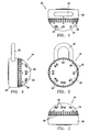
- Figures 1-6 illustrate one embodiment of a lock incorporating a illuminating mechanism for improved operability in areas of low light.
- the illuminating mechanism is housed within the lock body and when activated, provides light that allows the user to view the lock with sufficient light to allow for operation of the lock.
- light emits from areas, such as, for example, the numbers or number markers. Additionally, light may also emit through other features, such as a logo, the edges of the dial, or patterns formed in the dial, or any combination thereof.
- the light source can be used to improve operability of the lock in areas of low light and/or may provide an enhanced aesthetic appearance.
- Figures 1-4 illustrate only one exemplary embodiment of the present invention and that other embodiments incorporating the features disclosed herein are also contemplated. While the illustrative example is directed to a specific combination padlock, the features of the present invention could be applied to many other products, such as other combination locks, door locks, locker locks, padlocks or keyed locks.
- the lock 10 shown in Figures 1-6 includes the standard features of a combination lock, namely a lock body 20, a shackle 22, and a combination dial 24.
- the combination dial 24 includes numbers 26 and number markers 28, although other combination lock dial features may also be used.
- the combination lock 10 shown in Figures 1-6 may use any conventional locking mechanism.
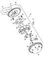
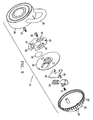
- FIG. 7 and 8 illustrates an exploded view of the lock 10 shown in Figures 1-6 .
- the lock 10 shown in Figures 7 and 8 includes dial base 30 located between the lock body 20 and the dial 24. Also illustrated is one embodiment of the illuminating mechanism. Included are a piezo device 33, a piezo wiper 35 having three piezo wiper springs 37, a print circuit board (PCB) 40, and a power source 42.
- the power source 42 is shown as several small coin cell lithium batteries, however it should be appreciated by one skilled in the art that any power source could be used.
- the power source may be batteries, fuel cells, solar power, or the like and will define the performance and several other properties or product characteristics of the lock and illuminating mechanism
- the illuminating mechanism is disposed within the lock dial 24 and thereby provides an area for the illuminating mechanism that is away from the locking mechanism. This allows the illuminating mechanism to be accessed without granting access to the locking mechanism, which would potentially compromise the integrity of the lock.
- the dial 24 is shown as a hollow semi-spherical shape, it should be appreciated that other embodiments can incorporate other types or configurations of the lock dial. The hollow, semi-spherical dial allows for ease of incorporation of the illuminating mechanism.
- the piezo wiper 35 is shown as a stamped metal disk with three wiper springs 37 and a tab 43 to engage a fixed point 44 in the lock body 20. Although three wiper springs 37 are shown, it should be appreciated that only a single wiper spring 37 is needed. It should be appreciated that any number of piezo wiper springs 37 can be used, however three piezo wiper springs are preferred in order to trigger the light on with one third of a dial rotation and to provide a balanced three point surface to support the dial base 30 evenly. Furthermore, the piezo wiper springs 37 can be tangent to the centerline of the lock body or can be perpendicular in orientation. The piezo wiper 35 is fixed in location with respect to the lock body 20.
- the piezo device 33 is mounted to the underside of the dial base 30 , by any known means including, but not limited to, snap fit, staking, adhesive or the like.
- the wiper springs 37 on the piezo wiper 35 brush against the piezo device 33, which produces a voltage signal, as described below.
- the dial base 30, zinc die cast as shown, is crimped to the lock body 20 and traps the piezo wiper 35 between dial base 30 and lock body 20.
- the dial base 30 rotates freely with respect to the lock body 20 in both directions.
- a PCB (Printed Circuit Board) 40 with one or more LED's 50 is attached with the PCB to the dial base 30 via any conventional means, such as a screw 51.
- LED's Light Emitting Diodes
- the use of the Light Emitting Diodes (LED's) provides illumination of a portion of the lock, such as the lock dial, thereby increasing visibility and ease of use during operation of the lock.
- the number and type of LED's depends on the amount of light that is desired.
- a reflector (not shown) is used to cover the PCB 40 and dial base 30 , while allowing the LED(s) to pass through and reside between the dial 24 and reflector.
- the reflector is preferably high gloss white in color or a metallic or mirror like finish to reflect the light produced by the LED(s) toward the dial.
- the PCB 40 is painted or coated with a reflective material. The use of a reflector or reflective coating is optional and is used to enhance or focus the light emitted from the LED(s).
- the dial 24 is generally composed of two contrasting materials.
- the outer surface with the exception of the illuminated areas, is made from a material that is solid such that light cannot transmit through it. Plastic or zinc die cast materials are the preferred.
- the inner surface material can be either be semi-transparent colored material with a white LED or semi-transparent clear with a colored LED. As such the color of the illumination can be varied by changing LED color or inner material color.
- the dial is composed of a single transparent material with markings, such as number on it.
- the dial is composed of an opaque material and more than one semitransparent materials or more than one color of semitransparent material. In such embodiments, the light emitted can be multi-colored for aesthetic purposes.
- Two dial screws 55 are used to hold the dial 24, power source 42, and the PCB 40 assembly to the dial base 30. Screws, bolts or other removable fastening means are used in order to allow the user to gain access to the power source 42, such as, for example, to change the batteries.
- the dial screws could be replaced by a more permanent fixation means, such as glue, staking or other attachment means. Such other attachment means are more readily used if the power source can operate the product for an acceptable time period.
- a small removable battery door (not shown) could be integrated into the dial which would allow permanent dial attachment.
- Pressing or rotating a lock dial 24 activates the LED's 50.
- the number of LED's 50 can be varied and will be determined by the amount of illumination desired.
- the LED's 50 will remain activated for predetermined time period after the dial 24 is released or ceases to rotate. For example, the LED's 50 may remain illuminated for a period of two to seven seconds. In other embodiments, the LED's 50 may remain illuminated a shorter or longer duration. Due to cost and space considerations, the circuitry should be kept simple and component costs should be relatively inexpensive. In addition, due to the limited battery power, the circuitry should also consume only small amounts of current.
- a circuit 60 with a Field Effect Transistor (FET) Q1 controls the LED(s) 50. While other mechanism can be used for controlling the LED(s) 50, a FET Q1 is preferred due to its high input impedance and allowance of a simple timing circuit that uses few components and low current draw (less then 1uA) in the in-active state.
- FET Field Effect Transistor
- a switch SW1 is used to charge capacitor C1. The charged capacitor C1 causes FET Q1 to turn “on” providing a low source/drain resistance which enables current to flow through LED 50. As long as SW1 is closed, or capacitor C1 is charged, Q1 remains in the "on” state.
- capacitor C1 When SW1 is released capacitor C1 slowly discharges through resistor R1 .
- the relative resistance of the resistor R1 determines the rate of capacitor discharge and thus the duration of the illumination event.
- the capacitor C1 discharges to a voltage less than the gate threshold of the FET Q1, the source/drain resistance becomes a relatively high impedance, thereby stopping current and FET Q1 and LED 50 are turned off. The circuit is now ready for another event.
- the circuit described above provides for a sufficient illuminating circuit
- the above circuit is difficult to use because the parked position that the dial is in could be a closed-switch position.
- the push dial wake-up feature can also contribute to low battery life because the dial can be inadvertently held down wasting battery life.
- Figure 10 details a circuit 70 that controls from a change in state versus a fixed low state.
- a second FET Q2 is added to the circuit that is pulsed to the "on" state from a capacitor coupled signal. Because the signal is capacitor coupled through capacitor C2, FET Q2 is only momentarily on, even if SW1 or SW2 are held in the "on” state. This causes capacitor C1 that holds Q1 "on” to only momentarily be charged and never be held in the charged state.
- the two switches SW1 and SW2 can be integrated into the printed circuit copper and two spring contacts off the board.
- An alternative embodiment is the implementation of a momentary switch.
- the capacitor C2 and the two switches SW1 and SW2 are replaced with a piezo device 33 to create circuit 80.
- a piezo device 33 To activate the LED(s) 50, rotating or pushing the dial 24 bends or flexes piezo device 33. This action causes the piezo device 33 to produce a voltage of sufficient magnitude to briefly turn "on” FET Q2.
- Using a piezo device 33 helps power consumption by adding energy to the circuit versus a passive switch or sensor that consumes energy from the battery. This is because a piezo device 33 generates surface charges in response to applied stresses. With FET Q2 turned “on”, its source/drain resistance approaches zero thereby allowing capacitor C1 to charge.
- the charged capacitor causes FET Q1 to turn “on” where it now has a low source/drain resistance which enables current to flow through LED 50.
- FET Q2 turned “off”
- the capacitor slowly discharges through resistor R1 holding FET Q1 "on”.
- the discharge time sets the LED "on” time.
- the FET source/drain resistance becomes a relatively high impedance, stopping current and FET Q1 and LED 50 are turned off.
- the circuit is now ready for another piezo event.
Landscapes
- Lighting Device Outwards From Vehicle And Optical Signal (AREA)
- Rotary Switch, Piano Key Switch, And Lever Switch (AREA)
- Lock And Its Accessories (AREA)
- Arrangement Of Elements, Cooling, Sealing, Or The Like Of Lighting Devices (AREA)
- Non-Portable Lighting Devices Or Systems Thereof (AREA)
Abstract
Description
- The present invention is directed to an improved combination lock, and more specifically to a combination lock which includes a means for illuminating a portion of the combination dial.
- Security devices, such as locks, are used in a variety of applications to secure a variety of objects. In some instances the security device may be used in areas of low light, which may impede or complicate operation of the security device. For example, operation of a combination dial to locate the correct number of the unlocking combination or locating the keyhole for insertion of the appropriate key may be difficult in areas of low light. As such, it is desirable to provide a security device that produces sufficient light to allow easy operation of the security device.
-
US-A-6345898 discloses an illuminated combination pad lock that illuminates in response to pressing in the combination dial or raising the shackle although still in the locked position. This document provides basis for the pre-characterising portion of independent claim 1 appended hereto. - A lock including an illuminating device which is actuated by the rotation of a lock dial to produce an illumination event is disclosed. The illumination event provides sufficient light on the lock such as to allow easier operation of the lock in areas of inadequate light. The lock includes a piezo device which creates electrical current to light one or more light emitting diodes for a predetermined duration of time.
- In the accompanying drawings, which are incorporated in and constitute a part of this specification, embodiments of the invention are illustrated, which, together with a general description of the invention given above, and the detailed description given below serve to illustrate the principles of this invention.
-
Fig 1 is a top view of an illustrative embodiment of a lock incorporating an illuminating mechanism. -
Fig. 2 is a front view of the lock shown inFig. 1 . -
Fig. 3 is a bottom view of the lock shown inFig. 1 . -
Fig. 4 is a side view of the lock shown inFig. 1 . -
Fig. 5 is a front perspective view of the lock shown inFig. 1 . -
Fig. 6 is a back perspective view of the lock shown inFig. 1 . -
Fig. 7 is a front exploded view of the lock shown inFig. 1 . -
Fig. 8 is a rear exploded view of the lock shown inFig. 1 . -
Fig. 9 is an example of a circuit for an illuminating mechanism. -
Fig. 10 is a second example of a circuit for an illuminating mechanism. -
Fig. 11 is a third example of a circuit for an illuminating mechanism. -
Figures 1-6 illustrate one embodiment of a lock incorporating a illuminating mechanism for improved operability in areas of low light. The illuminating mechanism is housed within the lock body and when activated, provides light that allows the user to view the lock with sufficient light to allow for operation of the lock. In the embodiment shown inFigures 1-6 , light emits from areas, such as, for example, the numbers or number markers. Additionally, light may also emit through other features, such as a logo, the edges of the dial, or patterns formed in the dial, or any combination thereof. The light source can be used to improve operability of the lock in areas of low light and/or may provide an enhanced aesthetic appearance. It should be appreciated thatFigures 1-4 illustrate only one exemplary embodiment of the present invention and that other embodiments incorporating the features disclosed herein are also contemplated. While the illustrative example is directed to a specific combination padlock, the features of the present invention could be applied to many other products, such as other combination locks, door locks, locker locks, padlocks or keyed locks. - The
lock 10 shown inFigures 1-6 includes the standard features of a combination lock, namely alock body 20, ashackle 22, and acombination dial 24. Thecombination dial 24 includesnumbers 26 andnumber markers 28, although other combination lock dial features may also be used. Thecombination lock 10 shown inFigures 1-6 may use any conventional locking mechanism. -
Figures 7 and8 , illustrates an exploded view of thelock 10 shown inFigures 1-6 . Thelock 10 shown inFigures 7 and8 includesdial base 30 located between thelock body 20 and thedial 24. Also illustrated is one embodiment of the illuminating mechanism. Included are apiezo device 33, apiezo wiper 35 having threepiezo wiper springs 37, a print circuit board (PCB) 40, and apower source 42. Thepower source 42 is shown as several small coin cell lithium batteries, however it should be appreciated by one skilled in the art that any power source could be used. For example the power source may be batteries, fuel cells, solar power, or the like and will define the performance and several other properties or product characteristics of the lock and illuminating mechanism - As shown in
Figures 7 and8 , the illuminating mechanism is disposed within thelock dial 24 and thereby provides an area for the illuminating mechanism that is away from the locking mechanism. This allows the illuminating mechanism to be accessed without granting access to the locking mechanism, which would potentially compromise the integrity of the lock. Furthermore, while thedial 24 is shown as a hollow semi-spherical shape, it should be appreciated that other embodiments can incorporate other types or configurations of the lock dial. The hollow, semi-spherical dial allows for ease of incorporation of the illuminating mechanism. - The
piezo wiper 35 is shown as a stamped metal disk with threewiper springs 37 and atab 43 to engage a fixedpoint 44 in thelock body 20. Although threewiper springs 37 are shown, it should be appreciated that only asingle wiper spring 37 is needed. It should be appreciated that any number ofpiezo wiper springs 37 can be used, however three piezo wiper springs are preferred in order to trigger the light on with one third of a dial rotation and to provide a balanced three point surface to support thedial base 30 evenly. Furthermore, thepiezo wiper springs 37 can be tangent to the centerline of the lock body or can be perpendicular in orientation. Thepiezo wiper 35 is fixed in location with respect to thelock body 20. Thepiezo device 33 is mounted to the underside of thedial base 30, by any known means including, but not limited to, snap fit, staking, adhesive or the like. The wiper springs 37 on thepiezo wiper 35 brush against thepiezo device 33, which produces a voltage signal, as described below. Thedial base 30, zinc die cast as shown, is crimped to thelock body 20 and traps thepiezo wiper 35 betweendial base 30 andlock body 20. Thedial base 30 rotates freely with respect to thelock body 20 in both directions. - A PCB (Printed Circuit Board) 40 with one or more LED's 50 is attached with the PCB to the
dial base 30 via any conventional means, such as ascrew 51. The use of the Light Emitting Diodes (LED's) provides illumination of a portion of the lock, such as the lock dial, thereby increasing visibility and ease of use during operation of the lock. The number and type of LED's depends on the amount of light that is desired. - In some embodiments a reflector (not shown) is used to cover the
PCB 40 anddial base 30, while allowing the LED(s) to pass through and reside between thedial 24 and reflector. The reflector is preferably high gloss white in color or a metallic or mirror like finish to reflect the light produced by the LED(s) toward the dial. In other embodiments, the PCB 40 is painted or coated with a reflective material. The use of a reflector or reflective coating is optional and is used to enhance or focus the light emitted from the LED(s). - The
dial 24 is generally composed of two contrasting materials. The outer surface, with the exception of the illuminated areas, is made from a material that is solid such that light cannot transmit through it. Plastic or zinc die cast materials are the preferred. The inner material that also protrudes to the outside surface at areas to be illuminated, such as, for example, thenumbers 26, logo (not shown), number marks 28, and other desired illuminated areas, is made of semitransparent plastic, such as, for example, polycarbonate or acrylic, which are typically used for light pipe applications. The inner surface material can be either be semi-transparent colored material with a white LED or semi-transparent clear with a colored LED. As such the color of the illumination can be varied by changing LED color or inner material color. In some embodiments, the dial is composed of a single transparent material with markings, such as number on it. In other embodiments, the dial is composed of an opaque material and more than one semitransparent materials or more than one color of semitransparent material. In such embodiments, the light emitted can be multi-colored for aesthetic purposes. - Two dial screws 55 are used to hold the
dial 24,power source 42, and thePCB 40 assembly to thedial base 30. Screws, bolts or other removable fastening means are used in order to allow the user to gain access to thepower source 42, such as, for example, to change the batteries. The dial screws could be replaced by a more permanent fixation means, such as glue, staking or other attachment means. Such other attachment means are more readily used if the power source can operate the product for an acceptable time period. Alternatively, a small removable battery door (not shown) could be integrated into the dial which would allow permanent dial attachment. - Pressing or rotating a
lock dial 24 activates the LED's 50. The number of LED's 50 can be varied and will be determined by the amount of illumination desired. The LED's 50 will remain activated for predetermined time period after thedial 24 is released or ceases to rotate. For example, the LED's 50 may remain illuminated for a period of two to seven seconds. In other embodiments, the LED's 50 may remain illuminated a shorter or longer duration. Due to cost and space considerations, the circuitry should be kept simple and component costs should be relatively inexpensive. In addition, due to the limited battery power, the circuitry should also consume only small amounts of current. - As shown in
Figure 9 , acircuit 60 with a Field Effect Transistor (FET) Q1 controls the LED(s) 50. While other mechanism can be used for controlling the LED(s) 50, a FET Q1 is preferred due to its high input impedance and allowance of a simple timing circuit that uses few components and low current draw (less then 1uA) in the in-active state. To activate the LED's 50 when pushing thedial 24, a switch SW1 is used to charge capacitor C1. The charged capacitor C1 causes FET Q1 to turn "on" providing a low source/drain resistance which enables current to flow throughLED 50. As long as SW1 is closed, or capacitor C1 is charged, Q1 remains in the "on" state. When SW1 is released capacitor C1 slowly discharges through resistor R1 . The relative resistance of the resistor R1 determines the rate of capacitor discharge and thus the duration of the illumination event. When the capacitor C1 discharges to a voltage less than the gate threshold of the FET Q1, the source/drain resistance becomes a relatively high impedance, thereby stopping current and FET Q1 andLED 50 are turned off. The circuit is now ready for another event. - While the circuit described above provides for a sufficient illuminating circuit, when implementing the rotating dial event wake feature, the above circuit is difficult to use because the parked position that the dial is in could be a closed-switch position. The push dial wake-up feature can also contribute to low battery life because the dial can be inadvertently held down wasting battery life.
-
Figure 10 details acircuit 70 that controls from a change in state versus a fixed low state. In order to achieve this a second FET Q2 is added to the circuit that is pulsed to the "on" state from a capacitor coupled signal. Because the signal is capacitor coupled through capacitor C2, FET Q2 is only momentarily on, even if SW1 or SW2 are held in the "on" state. This causes capacitor C1 that holds Q1 "on" to only momentarily be charged and never be held in the charged state. The two switches SW1 and SW2 can be integrated into the printed circuit copper and two spring contacts off the board. An alternative embodiment is the implementation of a momentary switch. - In
Figure 11 , the capacitor C2 and the two switches SW1 and SW2, are replaced with apiezo device 33 to createcircuit 80. To activate the LED(s) 50, rotating or pushing thedial 24 bends or flexespiezo device 33. This action causes thepiezo device 33 to produce a voltage of sufficient magnitude to briefly turn "on" FET Q2. Using apiezo device 33 helps power consumption by adding energy to the circuit versus a passive switch or sensor that consumes energy from the battery. This is because apiezo device 33 generates surface charges in response to applied stresses. With FET Q2 turned "on", its source/drain resistance approaches zero thereby allowing capacitor C1 to charge. The charged capacitor causes FET Q1 to turn "on" where it now has a low source/drain resistance which enables current to flow throughLED 50. With FET Q2 turned "off", the capacitor slowly discharges through resistor R1 holding FET Q1 "on". The discharge time sets the LED "on" time. When the capacitor discharges to a voltage less than the gate threshold of FET Q1, the FET source/drain resistance becomes a relatively high impedance, stopping current and FET Q1 andLED 50 are turned off. The circuit is now ready for another piezo event. - The invention has been described with reference to the preferred embodiment. Clearly, modifications and alterations will occur to others upon a reading and understanding of this specification. It is intended to include all such modifications and alterations insofar as they come within the scope of the appended claims.
Claims (10)
- A lock comprising:a lock body (20);a lock dial (24) coupled to said lock body; andan illuminating mechanism disposed within said lock dial (24);characterised in that:said illuminating mechanism includes a piezo device (33); andwherein said piezo device (33) produces a charge when said lock dial (24) is rotated relative to said lock body.
- The lock of claim 1, wherein said lock dial (24) is comprised of an opaque material and one or more semi-transparent materials.
- The lock of claim 2, wherein said lock dial (24) includes numbers and number markings comprised of said one or more semi-transparent materials.
- The lock of claim 1, wherein said illuminating mechanism includes one or more light emitting diodes (50).
- The lock of claim 1 further comprising a reflective surface located such that one or more light emitting diodes (50) are located between the reflective surface and an inner surface of said lock dial.
- The lock of claim 1, wherein said illuminating mechanism includes one or more field effect transistors (Q1), one or more resistors (R1) and one or more capacitors (C1).
- The lock of claim 6, wherein said one or more resistors (R1) determine the rate of discharge of one or more of said capacitors (C1), thereby determining the duration of an illumination event.
- The lock of claim 1, wherein the illuminating mechanism further comprises a piezo wiper (35) including one or more piezo wiper springs (37) and one or more light emitting diodes (50), wherein rotation of the lock dial (24) produces an illumination event, wherein said one or more light emitting diodes (24) illuminate a portion of said lock.
- The lock of claim 8, wherein said lock dial (24) comprises an opaque material and one or more semi-transparent materials, and wherein said one or more light emitting diodes (50) create said illumination event by emitting light through said one or more semi-transparent materials.
- The lock of claim 8 further comprising a means for predetermining the duration of said illumination event.
Applications Claiming Priority (2)
| Application Number | Priority Date | Filing Date | Title |
|---|---|---|---|
| US52120904P | 2004-03-11 | 2004-03-11 | |
| PCT/US2005/008132 WO2005088038A2 (en) | 2004-03-11 | 2005-03-10 | Illuminating mechanism for a lock |
Publications (2)
| Publication Number | Publication Date |
|---|---|
| EP1740790A2 EP1740790A2 (en) | 2007-01-10 |
| EP1740790B1 true EP1740790B1 (en) | 2010-01-27 |
Family
ID=34962456
Family Applications (1)
| Application Number | Title | Priority Date | Filing Date |
|---|---|---|---|
| EP05725349A Expired - Lifetime EP1740790B1 (en) | 2004-03-11 | 2005-03-10 | Illuminating mechanism for a lock |
Country Status (8)
| Country | Link |
|---|---|
| US (1) | US7367683B2 (en) |
| EP (1) | EP1740790B1 (en) |
| CN (1) | CN1965138B (en) |
| AT (1) | ATE456725T1 (en) |
| CA (1) | CA2559168C (en) |
| DE (1) | DE602005019148D1 (en) |
| MX (1) | MXPA06010399A (en) |
| WO (1) | WO2005088038A2 (en) |
Families Citing this family (19)
| Publication number | Priority date | Publication date | Assignee | Title |
|---|---|---|---|---|
| US7287882B2 (en) * | 2005-10-19 | 2007-10-30 | Jaeyou Co., Ltd. | Shining lock structure |
| US20070113026A1 (en) * | 2005-10-26 | 2007-05-17 | Beseda David J | Dedicated memory module for device |
| US20080196457A1 (en) * | 2007-02-08 | 2008-08-21 | Ilan Goldman | Combination lock with light indicators |
| US7537363B2 (en) * | 2007-03-01 | 2009-05-26 | Denso International America, Inc. | Insert molding dial structure |
| GB2453550B (en) * | 2007-10-08 | 2012-03-14 | Kenneth Lawrence Deavin | Colour coded combination lock |
| US7937879B2 (en) * | 2009-03-11 | 2011-05-10 | Sheltered Wings, Inc. | Rifle scope with a low-light visible element |
| US8166696B2 (en) | 2009-09-14 | 2012-05-01 | Sheltered Wings, Inc. | Rifle scope with adjustment stop |
| US8166697B1 (en) * | 2010-06-22 | 2012-05-01 | Sueskind Alan E | Rifle scope indicia system |
| USD679168S1 (en) | 2011-11-22 | 2013-04-02 | Master Lock Company Llc | Lock |
| US9677848B2 (en) | 2012-04-18 | 2017-06-13 | Sheltered Wings, Inc. | Multiple knob turret |
| US8919026B2 (en) | 2012-04-18 | 2014-12-30 | Sheltered Wings, Inc. | Rifle scope turret with spiral cam mechanism |
| USD683611S1 (en) | 2012-05-08 | 2013-06-04 | Greg L. Walter | Padlock with an LED |
| US9747739B2 (en) | 2014-08-18 | 2017-08-29 | Noke, Inc. | Wireless locking device |
| US9728022B2 (en) | 2015-01-28 | 2017-08-08 | Noke, Inc. | Electronic padlocks and related methods |
| USD760576S1 (en) | 2015-02-10 | 2016-07-05 | Master Lock Company Llc | Lock |
| US11105587B2 (en) | 2016-01-27 | 2021-08-31 | Sheltered Wings, Inc. | Turret with a zero stop |
| US10890015B2 (en) | 2018-09-21 | 2021-01-12 | Knox Associates, Inc. | Electronic lock state detection systems and methods |
| US11352817B2 (en) | 2019-01-25 | 2022-06-07 | Noke, Inc. | Electronic lock and interchangeable shackles |
| WO2022010625A2 (en) | 2020-06-16 | 2022-01-13 | Sheltered Wings, Inc. D/B/A Vortex Optics | Turret with a zero stop |
Family Cites Families (44)
| Publication number | Priority date | Publication date | Assignee | Title |
|---|---|---|---|---|
| US317772A (en) | 1885-05-12 | Half to a | ||
| US922065A (en) | 1906-09-17 | 1909-05-18 | Corbin Cabinet Lock Company | Lock. |
| US961884A (en) | 1909-05-17 | 1910-06-21 | Moses Mosler | Attachment for combination-dials on safes, vaults, &c. |
| US1000889A (en) | 1910-07-25 | 1911-08-15 | Phoenix Combination Lock Company | Lock. |
| US1302896A (en) | 1918-01-29 | 1919-05-06 | Mortimer B Burgess | Keyless lock. |
| US1302889A (en) * | 1918-02-01 | 1919-05-06 | Jose Antonio Albisu | Air-motor. |
| US1525124A (en) | 1924-02-16 | 1925-02-03 | Pittsburgh Plate Glass Co | Apparatus for handling glass sheets |
| DE622255C (en) | 1933-11-21 | 1935-11-23 | Johann Wolf | Mallock with a latch bolt secured by several tumblers |
| US2153831A (en) | 1938-02-15 | 1939-04-11 | Gudge Herbert | Safety lock |
| US2566490A (en) | 1950-08-14 | 1951-09-04 | Heinz Bernard | Luminous attachment for door knobs |
| US4078248A (en) | 1976-09-08 | 1978-03-07 | Daniel Hill | Lock light |
| US4453390A (en) | 1981-01-14 | 1984-06-12 | Wormald International Limited | Combination lock monitoring system |
| US4455552A (en) | 1981-11-24 | 1984-06-19 | Sargent & Greenleaf, Inc. | Combination locks with electro-optical silent alarm system |
| DE3411777A1 (en) | 1983-11-02 | 1985-05-09 | Fa. R. und W. Nienstedt, 2808 Syke | PERMUTATION LOCK |
| US4819465A (en) | 1983-11-25 | 1989-04-11 | Hot Locks, Inc. | Padlock cover |
| US4631940A (en) | 1985-03-29 | 1986-12-30 | Sargent & Greenleaf, Inc. | Digital readout combination lock dial assembly |
| USD306131S (en) | 1987-06-26 | 1990-02-20 | Coffman David M | Illuminated holder for combination padlocks |
| DE8806772U1 (en) | 1988-05-24 | 1988-07-28 | Schmaunz, Johann, 8000 München | Bicycle lock with permutation locking device |
| US5015918A (en) * | 1988-07-22 | 1991-05-14 | John Copeland | Bicycle single-wire lighting system with steady-flashing-reflector rear warning device |
| US5179325A (en) | 1991-01-02 | 1993-01-12 | Aragon Jr William G | Touch-sensitive illuminable door lock |
| US5057975A (en) | 1991-02-19 | 1991-10-15 | Evigan Gregory R | Apparatus for illuminating a keyhole |
| US5522243A (en) | 1992-07-16 | 1996-06-04 | Kusmiss; John H. | Daylight fluorescent color combination lock with optional additional indicia |
| US5664446A (en) | 1992-07-16 | 1997-09-09 | Kusmiss; John H. | Combination lock with nonnumerical indicia |
| DE9209902U1 (en) | 1992-07-23 | 1992-10-22 | Burg-Wächter KG Alfred Lüling, 58540 Meinerzhagen | Control element for an electronic lock |
| US5604489A (en) | 1992-10-09 | 1997-02-18 | Medeco Security Locks, Inc. | Alphanumeric input terminal |
| AU5578994A (en) | 1992-11-12 | 1994-06-08 | Garth Robert Chadfield | Padlock with tamper alarm |
| US5493279A (en) | 1993-03-24 | 1996-02-20 | Mas-Hamilton Group | Electronic combination lock with covert entry detection feature and method of covert entry detection |
| GB9311099D0 (en) | 1993-05-28 | 1993-07-14 | White Peter A | Improvements in locks for bicycles and the like |
| US5404735A (en) | 1994-03-15 | 1995-04-11 | Hsieh; Chen-Kuei | Padlock with built-in anti-theft alarm device |
| US5546776A (en) | 1994-11-21 | 1996-08-20 | Sun; Min-Hsiung | Padlock and lock holder unit |
| US6047575A (en) | 1995-05-19 | 2000-04-11 | Slc Technologies, Inc. | Electronic padlock |
| US5684457A (en) | 1995-06-01 | 1997-11-04 | C&M Technology, Inc. | Tamper indication system for combination locks |
| JP3576720B2 (en) | 1996-10-15 | 2004-10-13 | 株式会社東海理化電機製作所 | Dial operating device |
| USD397026S (en) | 1997-01-29 | 1998-08-18 | Robert Drake | Lighted cover for circular padlocks |
| US5727405A (en) | 1997-02-03 | 1998-03-17 | Cromwell; Daryl | Alarm padlock |
| US5832752A (en) | 1997-05-01 | 1998-11-10 | Zeller; Noel E. | Portable cable lock |
| US6086223A (en) * | 1998-03-15 | 2000-07-11 | Fogle; Mary | Pad lock lighting devices |
| US6019480A (en) | 1998-04-09 | 2000-02-01 | Innovative Scuba Cocepts, Inc. | Marker light assembly |
| DE29816299U1 (en) * | 1998-09-14 | 2000-01-20 | Sudhaus GmbH & Co., 58644 Iserlohn | Combination lock |
| JP3621595B2 (en) | 1999-01-11 | 2005-02-16 | 株式会社東海理化電機製作所 | Key insertion hole structure |
| USD427884S (en) | 1999-08-26 | 2000-07-11 | Francisco Castellanos | Wireless digital combination lock |
| US6345898B1 (en) | 2000-12-05 | 2002-02-12 | Atico International Usa, Inc | Illuminated pad lock |
| US20030012020A1 (en) * | 2001-07-14 | 2003-01-16 | King Peter C. | Pad lock illumination device |
| TW547679U (en) * | 2002-12-30 | 2003-08-11 | Teddy Co Ltd | Luminous clock |
-
2005
- 2005-03-10 AT AT05725349T patent/ATE456725T1/en not_active IP Right Cessation
- 2005-03-10 US US10/906,884 patent/US7367683B2/en not_active Expired - Fee Related
- 2005-03-10 WO PCT/US2005/008132 patent/WO2005088038A2/en not_active Ceased
- 2005-03-10 CA CA002559168A patent/CA2559168C/en not_active Expired - Fee Related
- 2005-03-10 DE DE602005019148T patent/DE602005019148D1/en not_active Expired - Fee Related
- 2005-03-10 EP EP05725349A patent/EP1740790B1/en not_active Expired - Lifetime
- 2005-03-10 CN CN2005800151439A patent/CN1965138B/en not_active Expired - Fee Related
- 2005-03-10 MX MXPA06010399A patent/MXPA06010399A/en active IP Right Grant
Also Published As
| Publication number | Publication date |
|---|---|
| MXPA06010399A (en) | 2007-05-04 |
| WO2005088038A2 (en) | 2005-09-22 |
| CA2559168A1 (en) | 2005-09-22 |
| DE602005019148D1 (en) | 2010-03-18 |
| US20050201076A1 (en) | 2005-09-15 |
| CA2559168C (en) | 2009-09-29 |
| WO2005088038A3 (en) | 2005-11-10 |
| CN1965138B (en) | 2011-09-07 |
| US7367683B2 (en) | 2008-05-06 |
| EP1740790A2 (en) | 2007-01-10 |
| ATE456725T1 (en) | 2010-02-15 |
| CN1965138A (en) | 2007-05-16 |
Similar Documents
| Publication | Publication Date | Title |
|---|---|---|
| CA2559168C (en) | Illuminating mechanism for a lock | |
| US7482712B2 (en) | DC power supply with input voltage polarity indication | |
| US6047575A (en) | Electronic padlock | |
| US6991344B2 (en) | LED flashlight having a clip made of a resilient material | |
| US4293894A (en) | Battery operated illuminating device | |
| US20180058098A1 (en) | Locks with integral illumination | |
| US10352512B1 (en) | Device for illuminating a door knob keyhole | |
| GB2374564A (en) | Support for functional elements especially a set of tools or a pocket knife | |
| US4475067A (en) | Door lock illuminating device | |
| US6461005B2 (en) | Illuminated pad lock | |
| US9642220B1 (en) | Keyway illumination system | |
| US20030206495A1 (en) | Alarm clock with dial illumination | |
| US8256917B2 (en) | Security safe light module | |
| JPH08246719A (en) | Door handle | |
| US20050002181A1 (en) | Illuminated cosmetic case structure | |
| CN102061836B (en) | Key with prompting function | |
| CN117211618A (en) | A door handle, door and vehicle | |
| KR200249631Y1 (en) | Multi-function rotating key | |
| KR200200008Y1 (en) | Used indicator for public toilet | |
| CN117198792A (en) | A knob with a built-in magnetic switch | |
| JP2591858Y2 (en) | Tap with indicator light | |
| KR200184123Y1 (en) | A key having an illuminating light | |
| JPH08284496A (en) | Key head case | |
| KR200272993Y1 (en) | A luminous accessory | |
| JPH11247502A (en) | Portable key storage case |
Legal Events
| Date | Code | Title | Description |
|---|---|---|---|
| PUAI | Public reference made under article 153(3) epc to a published international application that has entered the european phase |
Free format text: ORIGINAL CODE: 0009012 |
|
| 17P | Request for examination filed |
Effective date: 20061003 |
|
| AK | Designated contracting states |
Kind code of ref document: A2 Designated state(s): AT BE BG CH CY CZ DE DK EE ES FI FR GB GR HU IE IS IT LI LT LU MC NL PL PT RO SE SI SK TR |
|
| 17Q | First examination report despatched |
Effective date: 20070306 |
|
| DAX | Request for extension of the european patent (deleted) | ||
| GRAP | Despatch of communication of intention to grant a patent |
Free format text: ORIGINAL CODE: EPIDOSNIGR1 |
|
| GRAS | Grant fee paid |
Free format text: ORIGINAL CODE: EPIDOSNIGR3 |
|
| GRAA | (expected) grant |
Free format text: ORIGINAL CODE: 0009210 |
|
| AK | Designated contracting states |
Kind code of ref document: B1 Designated state(s): AT BE BG CH CY CZ DE DK EE ES FI FR GB GR HU IE IS IT LI LT LU MC NL PL PT RO SE SI SK TR |
|
| REG | Reference to a national code |
Ref country code: GB Ref legal event code: FG4D |
|
| REG | Reference to a national code |
Ref country code: CH Ref legal event code: EP |
|
| REG | Reference to a national code |
Ref country code: IE Ref legal event code: FG4D |
|
| REF | Corresponds to: |
Ref document number: 602005019148 Country of ref document: DE Date of ref document: 20100318 Kind code of ref document: P |
|
| REG | Reference to a national code |
Ref country code: NL Ref legal event code: VDEP Effective date: 20100127 |
|
| LTIE | Lt: invalidation of european patent or patent extension |
Effective date: 20100127 |
|
| PG25 | Lapsed in a contracting state [announced via postgrant information from national office to epo] |
Ref country code: AT Free format text: LAPSE BECAUSE OF FAILURE TO SUBMIT A TRANSLATION OF THE DESCRIPTION OR TO PAY THE FEE WITHIN THE PRESCRIBED TIME-LIMIT Effective date: 20100127 |
|
| PG25 | Lapsed in a contracting state [announced via postgrant information from national office to epo] |
Ref country code: NL Free format text: LAPSE BECAUSE OF FAILURE TO SUBMIT A TRANSLATION OF THE DESCRIPTION OR TO PAY THE FEE WITHIN THE PRESCRIBED TIME-LIMIT Effective date: 20100127 Ref country code: PT Free format text: LAPSE BECAUSE OF FAILURE TO SUBMIT A TRANSLATION OF THE DESCRIPTION OR TO PAY THE FEE WITHIN THE PRESCRIBED TIME-LIMIT Effective date: 20100527 Ref country code: LT Free format text: LAPSE BECAUSE OF FAILURE TO SUBMIT A TRANSLATION OF THE DESCRIPTION OR TO PAY THE FEE WITHIN THE PRESCRIBED TIME-LIMIT Effective date: 20100127 Ref country code: ES Free format text: LAPSE BECAUSE OF FAILURE TO SUBMIT A TRANSLATION OF THE DESCRIPTION OR TO PAY THE FEE WITHIN THE PRESCRIBED TIME-LIMIT Effective date: 20100508 Ref country code: IS Free format text: LAPSE BECAUSE OF FAILURE TO SUBMIT A TRANSLATION OF THE DESCRIPTION OR TO PAY THE FEE WITHIN THE PRESCRIBED TIME-LIMIT Effective date: 20100527 |
|
| PG25 | Lapsed in a contracting state [announced via postgrant information from national office to epo] |
Ref country code: PL Free format text: LAPSE BECAUSE OF FAILURE TO SUBMIT A TRANSLATION OF THE DESCRIPTION OR TO PAY THE FEE WITHIN THE PRESCRIBED TIME-LIMIT Effective date: 20100127 Ref country code: SI Free format text: LAPSE BECAUSE OF FAILURE TO SUBMIT A TRANSLATION OF THE DESCRIPTION OR TO PAY THE FEE WITHIN THE PRESCRIBED TIME-LIMIT Effective date: 20100127 Ref country code: FI Free format text: LAPSE BECAUSE OF FAILURE TO SUBMIT A TRANSLATION OF THE DESCRIPTION OR TO PAY THE FEE WITHIN THE PRESCRIBED TIME-LIMIT Effective date: 20100127 |
|
| PG25 | Lapsed in a contracting state [announced via postgrant information from national office to epo] |
Ref country code: EE Free format text: LAPSE BECAUSE OF FAILURE TO SUBMIT A TRANSLATION OF THE DESCRIPTION OR TO PAY THE FEE WITHIN THE PRESCRIBED TIME-LIMIT Effective date: 20100127 Ref country code: CY Free format text: LAPSE BECAUSE OF FAILURE TO SUBMIT A TRANSLATION OF THE DESCRIPTION OR TO PAY THE FEE WITHIN THE PRESCRIBED TIME-LIMIT Effective date: 20100127 Ref country code: BE Free format text: LAPSE BECAUSE OF FAILURE TO SUBMIT A TRANSLATION OF THE DESCRIPTION OR TO PAY THE FEE WITHIN THE PRESCRIBED TIME-LIMIT Effective date: 20100127 Ref country code: SE Free format text: LAPSE BECAUSE OF FAILURE TO SUBMIT A TRANSLATION OF THE DESCRIPTION OR TO PAY THE FEE WITHIN THE PRESCRIBED TIME-LIMIT Effective date: 20100127 Ref country code: RO Free format text: LAPSE BECAUSE OF FAILURE TO SUBMIT A TRANSLATION OF THE DESCRIPTION OR TO PAY THE FEE WITHIN THE PRESCRIBED TIME-LIMIT Effective date: 20100127 Ref country code: MC Free format text: LAPSE BECAUSE OF NON-PAYMENT OF DUE FEES Effective date: 20100331 Ref country code: GR Free format text: LAPSE BECAUSE OF FAILURE TO SUBMIT A TRANSLATION OF THE DESCRIPTION OR TO PAY THE FEE WITHIN THE PRESCRIBED TIME-LIMIT Effective date: 20100428 |
|
| REG | Reference to a national code |
Ref country code: CH Ref legal event code: PL |
|
| PG25 | Lapsed in a contracting state [announced via postgrant information from national office to epo] |
Ref country code: BG Free format text: LAPSE BECAUSE OF FAILURE TO SUBMIT A TRANSLATION OF THE DESCRIPTION OR TO PAY THE FEE WITHIN THE PRESCRIBED TIME-LIMIT Effective date: 20100427 Ref country code: CZ Free format text: LAPSE BECAUSE OF FAILURE TO SUBMIT A TRANSLATION OF THE DESCRIPTION OR TO PAY THE FEE WITHIN THE PRESCRIBED TIME-LIMIT Effective date: 20100127 Ref country code: SK Free format text: LAPSE BECAUSE OF FAILURE TO SUBMIT A TRANSLATION OF THE DESCRIPTION OR TO PAY THE FEE WITHIN THE PRESCRIBED TIME-LIMIT Effective date: 20100127 |
|
| PLBE | No opposition filed within time limit |
Free format text: ORIGINAL CODE: 0009261 |
|
| STAA | Information on the status of an ep patent application or granted ep patent |
Free format text: STATUS: NO OPPOSITION FILED WITHIN TIME LIMIT |
|
| REG | Reference to a national code |
Ref country code: FR Ref legal event code: ST Effective date: 20101130 |
|
| 26N | No opposition filed |
Effective date: 20101028 |
|
| PG25 | Lapsed in a contracting state [announced via postgrant information from national office to epo] |
Ref country code: FR Free format text: LAPSE BECAUSE OF NON-PAYMENT OF DUE FEES Effective date: 20100331 Ref country code: IE Free format text: LAPSE BECAUSE OF NON-PAYMENT OF DUE FEES Effective date: 20100310 Ref country code: DK Free format text: LAPSE BECAUSE OF FAILURE TO SUBMIT A TRANSLATION OF THE DESCRIPTION OR TO PAY THE FEE WITHIN THE PRESCRIBED TIME-LIMIT Effective date: 20100127 |
|
| PG25 | Lapsed in a contracting state [announced via postgrant information from national office to epo] |
Ref country code: DE Free format text: LAPSE BECAUSE OF NON-PAYMENT OF DUE FEES Effective date: 20101001 Ref country code: CH Free format text: LAPSE BECAUSE OF NON-PAYMENT OF DUE FEES Effective date: 20100331 Ref country code: LI Free format text: LAPSE BECAUSE OF NON-PAYMENT OF DUE FEES Effective date: 20100331 |
|
| PG25 | Lapsed in a contracting state [announced via postgrant information from national office to epo] |
Ref country code: IT Free format text: LAPSE BECAUSE OF FAILURE TO SUBMIT A TRANSLATION OF THE DESCRIPTION OR TO PAY THE FEE WITHIN THE PRESCRIBED TIME-LIMIT Effective date: 20100127 |
|
| PGFP | Annual fee paid to national office [announced via postgrant information from national office to epo] |
Ref country code: GB Payment date: 20110325 Year of fee payment: 7 |
|
| PG25 | Lapsed in a contracting state [announced via postgrant information from national office to epo] |
Ref country code: LU Free format text: LAPSE BECAUSE OF NON-PAYMENT OF DUE FEES Effective date: 20100310 Ref country code: HU Free format text: LAPSE BECAUSE OF FAILURE TO SUBMIT A TRANSLATION OF THE DESCRIPTION OR TO PAY THE FEE WITHIN THE PRESCRIBED TIME-LIMIT Effective date: 20100728 |
|
| PG25 | Lapsed in a contracting state [announced via postgrant information from national office to epo] |
Ref country code: TR Free format text: LAPSE BECAUSE OF FAILURE TO SUBMIT A TRANSLATION OF THE DESCRIPTION OR TO PAY THE FEE WITHIN THE PRESCRIBED TIME-LIMIT Effective date: 20100127 |
|
| GBPC | Gb: european patent ceased through non-payment of renewal fee |
Effective date: 20120310 |
|
| PG25 | Lapsed in a contracting state [announced via postgrant information from national office to epo] |
Ref country code: GB Free format text: LAPSE BECAUSE OF NON-PAYMENT OF DUE FEES Effective date: 20120310 |