EP1740456B1 - Aircraft turbine engine provided with an improved aerodynamic installation - Google Patents
Aircraft turbine engine provided with an improved aerodynamic installation Download PDFInfo
- Publication number
- EP1740456B1 EP1740456B1 EP05758188A EP05758188A EP1740456B1 EP 1740456 B1 EP1740456 B1 EP 1740456B1 EP 05758188 A EP05758188 A EP 05758188A EP 05758188 A EP05758188 A EP 05758188A EP 1740456 B1 EP1740456 B1 EP 1740456B1
- Authority
- EP
- European Patent Office
- Prior art keywords
- angle
- axis
- cowlings
- downstream
- engine
- Prior art date
- Legal status (The legal status is an assumption and is not a legal conclusion. Google has not performed a legal analysis and makes no representation as to the accuracy of the status listed.)
- Not-in-force
Links
- 238000009434 installation Methods 0.000 title 1
- 238000011144 upstream manufacturing Methods 0.000 claims description 7
- 238000012423 maintenance Methods 0.000 claims description 3
- 238000007789 sealing Methods 0.000 claims description 3
- 230000005540 biological transmission Effects 0.000 claims 2
- 241000256259 Noctuidae Species 0.000 description 4
- 239000007789 gas Substances 0.000 description 4
- 238000002485 combustion reaction Methods 0.000 description 2
- 230000000295 complement effect Effects 0.000 description 2
- 238000010586 diagram Methods 0.000 description 2
- 208000031968 Cadaver Diseases 0.000 description 1
- 230000009286 beneficial effect Effects 0.000 description 1
- 230000000694 effects Effects 0.000 description 1
- 238000005259 measurement Methods 0.000 description 1
- 238000000034 method Methods 0.000 description 1
- 238000012986 modification Methods 0.000 description 1
- 230000004048 modification Effects 0.000 description 1
- 230000002028 premature Effects 0.000 description 1
Images

Classifications
-
- B—PERFORMING OPERATIONS; TRANSPORTING
- B64—AIRCRAFT; AVIATION; COSMONAUTICS
- B64D—EQUIPMENT FOR FITTING IN OR TO AIRCRAFT; FLIGHT SUITS; PARACHUTES; ARRANGEMENT OR MOUNTING OF POWER PLANTS OR PROPULSION TRANSMISSIONS IN AIRCRAFT
- B64D29/00—Power-plant nacelles, fairings, or cowlings
- B64D29/08—Inspection panels for power plants
-
- B—PERFORMING OPERATIONS; TRANSPORTING
- B64—AIRCRAFT; AVIATION; COSMONAUTICS
- B64D—EQUIPMENT FOR FITTING IN OR TO AIRCRAFT; FLIGHT SUITS; PARACHUTES; ARRANGEMENT OR MOUNTING OF POWER PLANTS OR PROPULSION TRANSMISSIONS IN AIRCRAFT
- B64D29/00—Power-plant nacelles, fairings, or cowlings
Definitions
- the present invention relates, in general, to a turbo-propulsion unit for an aircraft comprising in particular, from upstream to downstream with reference to the direction of flow of the gases, a reactor provided with a fan casing and a gas ejection system, coaxial with an engine axis, said gas ejection system including two half-cowlings of hindquarters, said D-ducts, each articulated about an axis, which allows them to pass , for maintenance purposes, from a closed position to an open position.
- said half-underbody cowlings are furthermore connected to the downstream end of the fan casing via means for sealing and transmitting forces, having complementary female and male profiles, "V-blade / V-groove" (V-blade / V-groove), the male profile belonging to the rear half-cowlings and the female profile belonging to the fan-blade side.
- V-blade / V-groove V-blade / V-groove
- a turbo-propulsion unit according to the preambles of claim 1 and 4 is known from document EP-A-1,174,341 .
- the document EP-A-0 744 339 shows a half-cowling of a nacelle where the angle ⁇ is between 2 ° and 7 °. However, it is not a half-rear body cowling connected to the fan case. In addition, the angle ⁇ of the junction plane is not mentioned.
- the axes of articulation diverge towards the downstream.
- the document US-A-5,203,525 shows two half-cowls arranged on the engine by means of two displaced axes of articulation; said axes being apparently parallel to the axis of the motor and to each other.
- the downstream outlet plane of the fan casing is strictly perpendicular to the motor axis and the axes of articulation of the half-cowls are parallel to each other and inclined at an angle ⁇ with respect to the motor axis.
- angle which can not exceed 2 to 3 ° because, beyond, the system "V-blade / V-groove" would have difficulty to engage properly due to a "chisel” effect and, moreover, the Increased friction resulting from such a difficult engagement would result in premature wear.
- the present invention provides a solution for such an increase in the angle ⁇ while maintaining proper operation of the system "V-blade / V-groove".
- the angle ⁇ that the hinge axes make with the motor axis is greater than 3 ° and the junction plane between the rear body half-cowls and the downstream end of the housing. blower is, with the plane perpendicular to the motor axis, an angle ⁇ such that the difference between the angle ⁇ and the angle ⁇ is less than or equal to about 3 °.
- the angle ⁇ is preferably less than or equal to 6 °.
- the axes of articulation of the rear-body half-cowls are fixed to a pylon, which is a streamlined structure integrated into the structure of said wing and, in the known art, the axes of articulation are strictly parallel to each other and to the axis of the pylon.
- the invention proposes in addition to the increase of the angle ⁇ and the inclination ⁇ of the plane of the system "V-blade / V- groove ", or alternatively to these means, to make said hinge axes converge towards each other in the downstream direction.
- the angle of convergence, with respect to the axis of the pylon, is preferably of the order of 1 °, the hinge pins making, therefore, between them, an angle of the order of 2 °.
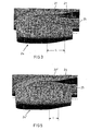
- the figure 1 represents a propulsion system according to the prior art and which shows the air inlet 1, the fan or fan 2, the fan casing 3, the compressors 4, the combustion chamber 5, the turbine casing 6 and the exhaust nozzle which is a common exhaust nozzle (mixed hot and cold gases), commonly called CNA, according to the English nomenclature "common nozzle assembly”.
- CNA common exhaust nozzle
- the system comprises, in addition, a two-part engine cover 9a, 9b and a two-part rear body cover 10a, 10b adapted to surround the assembly formed by the compressors 4, the combustion chamber 5 and the casing turbine 6, the division into two parts of the engine hood and the rear body cowling being made in a substantially vertical section plane.
- Each rear-body half-cowl 10a, 10b commonly referred to as D-duct, has three aerodynamic surfaces or skins, namely an outer nacelle surface 11, an outer fan duct surface 12 and an inner duct surface. Blower 13.
- the surfaces 12 and 13 define a half-blower channel (cold flow), respectively, 14a and 14b.
- the CNA 7 which, in normal operation, is connected to the rear body half-cowls, has two aerodynamic surfaces, namely the outer surface of the nacelle 15 and the inner surface of the hot and cold flow channel. 16. Thrust reverser doors 17 are implanted in the cowling 10a, 10b to act on the cold flow.
- the engine bonnet and the rear body bonnet are each formed of two halves, respectively 9a, 9b and 10a, 10b, but the common nozzle or CNA 7 is in one piece.
- the half-covers 9a, 9b and the half-cowlings 10a, 10b are mounted articulated on the driving beam (not shown) by means of hinges, respectively 18 and 19.
- the half-cowls 9a, 9b and the half-cowlings 10a, 10b comprise locks such as 20 and 21 for locking them in the closed position. It is understood that this assembly in two articulated parts is intended to allow easier access to the cold and hot parts of the reactor.
- V-blade / V-groove whose position on the upstream end of the half-cowling 10b is indicated at 22, for connection to the fan casing 3.
- Complementary structures, such as 23 ( figure 2 ) are positioned vis-a-vis on said housing.
- the plane of junction ZZ '(Z 1 -Z 1 ' to figure 4 ) of the "V-blade / V-groove" system merges with a plane YY 'perpendicular to the axis XX' of the engine so that the angle ⁇ 1 ( figure 4 ) between the two planes is zero.
- V-blade / V-groove A similar "V-blade / V-groove" system is provided between the downstream edge of the half-cowlings 10a, 10b and the upstream edge of the DAC 7 and, in this case also, the joining plane of the "V-blade” system. / V-groove "merges with a plane perpendicular to the axis XX 'of the engine.
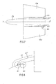
- the figure 3 shows a nacelle 24 mounted on a pylon 25 depending on the wing 26 of an aircraft.
- a zone, indicated at 27, of length L protrudes with respect to the general profile of the nacelle 24. This is due to the presence of the fairing of the hinges 19, which are arranged along an axis of articulation A1 ( figure 4 ) which makes an angle ⁇ 1 ⁇ 3 ° with the axis XX 'of the motor.
- this angle is brought to ⁇ 2 > 3, so that the axis of articulation now occupies the position A 2 and, simultaneously, it is given an angle ⁇ 2 to the junction plane of the "V" system. blade / V-groove ", thus becoming Z 2 -Z 2 ', with respect to the plane YY'.
- This angle ⁇ 2 is such that ⁇ 2 - ⁇ 2 ⁇ 3.
- the joining plane of the "V-blade / V-groove" system between the downstream edge of the rear body half-cowlings 10a, 10b and the upstream edge of the CNA 7 must, according to the invention. , be inclined at an angle ⁇ 2 , relative to the plane perpendicular to the axis XX 'of the engine, as is the joining plane of the system "V-blade / V-groove" between the upstream edge of the half-cowlings 10a, 10b and the downstream edge of the fan casing 3.
- the projection can be further reduced by using another measure illustrated Figures 7 and 8 .
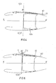
- the figure 7 shows schematically the pylon 25 and the two half-cowlings of the rear body 10a, 10b with their axes of articulation.
- the hinge pins occupy the position A1, that is to say they are parallel to each other and parallel to the longitudinal axis PP 'of the pylon 25. At this position corresponds the projection illustrated in 27 to figures 3 , 4 and 8 .
Landscapes
- Engineering & Computer Science (AREA)
- Aviation & Aerospace Engineering (AREA)
- Structures Of Non-Positive Displacement Pumps (AREA)
Abstract
Description
La présente invention concerne, d'une manière générale, un groupe turbo-propulseur pour aéronef comprenant notamment, de l'amont à l'aval par référence au sens d'écoulement des gaz, un réacteur pourvu d'un carter de soufflante et un système d'éjection des gaz, coaxiaux à un axe moteur, ledit système d'éjection des gaz incluant deux demi-capotages d'arrière-corps, dits D-ducts, articulés chacun autour d'un axe, ce qui leur permet de passer, à des fins d'opérations de maintenance, d'une position fermée à une position ouverte.The present invention relates, in general, to a turbo-propulsion unit for an aircraft comprising in particular, from upstream to downstream with reference to the direction of flow of the gases, a reactor provided with a fan casing and a gas ejection system, coaxial with an engine axis, said gas ejection system including two half-cowlings of hindquarters, said D-ducts, each articulated about an axis, which allows them to pass , for maintenance purposes, from a closed position to an open position.
En position fermée, lesdits demi-capotages d'arrière-corps viennent, en outre, se relier à l'extrémité aval du carter de soufflante via un moyen d'étanchéité et de transmission d'efforts, ayant des profils femelle et mâle complémentaires, dit "V-blade/V-groove" (lame en V/rainure en V), le profil mâle appartenant aux demi-capotages d'arrière-corps et le profil femelle appartenant au côté carter de soufflante.In the closed position, said half-underbody cowlings are furthermore connected to the downstream end of the fan casing via means for sealing and transmitting forces, having complementary female and male profiles, "V-blade / V-groove" (V-blade / V-groove), the male profile belonging to the rear half-cowlings and the female profile belonging to the fan-blade side.
Un groupe turbo-propulseur selon les préambules de la revendication 1 et 4 est connu du document
Dans la technique connue, le plan de sortie aval du carter de soufflante est rigoureusement perpendiculaire à l'axe moteur et les axes d'articulation des demi-capotages sont parallèles entre eux et inclinés d'un angle α par rapport à l'axe moteur, angle qui ne peut excéder 2 à 3° car, au-delà, le système "V-blade/V-groove" aurait du mal à s'engager correctement en raison d'un effet "ciseau" et, en outre, le frottement accru résultant d'un tel engagement difficile aboutirait à une usure prématurée.In the known art, the downstream outlet plane of the fan casing is strictly perpendicular to the motor axis and the axes of articulation of the half-cowls are parallel to each other and inclined at an angle α with respect to the motor axis. , angle which can not exceed 2 to 3 ° because, beyond, the system "V-blade / V-groove" would have difficulty to engage properly due to a "chisel" effect and, moreover, the Increased friction resulting from such a difficult engagement would result in premature wear.
Cependant, il y aurait un intérêt à augmenter cet angle α pour réduire l'importance de la saillie qu'implique le carénage des charnières définissant les axes d'articulation des demi-capotages d'arrière-corps. Une telle saillie complique, en effet, la définition aérodynamique de la zone concernée.However, it would be advantageous to increase this angle α to reduce the importance of the protrusion implied by the fairing of the hinges defining the hinge axes of the half-cowling hindquarters. Such a projection complicates, in fact, the aerodynamic definition of the area concerned.
La présente invention apporte une solution permettant une telle augmentation de l'angle α tout en conservant un fonctionnement correct du système "V-blade/V-groove".The present invention provides a solution for such an increase in the angle α while maintaining proper operation of the system "V-blade / V-groove".
Ainsi, selon l'invention, l'angle α que font les axes d'articulation avec l'axe moteur est supérieur à 3° et le plan de jonction entre les demi-capotages d'arrière-corps et l'extrémité aval du carter de soufflante fait, avec le plan perpendiculaire à l'axe moteur, un angle β tel que la différence entre l'angle α et l'angle β est inférieure ou égale à environ 3°.Thus, according to the invention, the angle α that the hinge axes make with the motor axis is greater than 3 ° and the junction plane between the rear body half-cowls and the downstream end of the housing. blower is, with the plane perpendicular to the motor axis, an angle β such that the difference between the angle α and the angle β is less than or equal to about 3 °.
On comprend que cela implique une modification de l'arrière du carter de soufflante du réacteur et de l'avant des demi-capotages d'arrière-corps portant respectivement les parties femelle et mâle du système "V-blade/V-groove", mais il en résulte une réduction significative de la saillie des charnières précitées.It will be understood that this involves a modification of the rear of the reactor fan casing and of the front of the rear body half-cowlings respectively carrying the female and male parts of the "V-blade / V-groove" system, but this results in a significant reduction in the projection of the aforementioned hinges.
Il n'est cependant pas possible de porter à une valeur quelconque les angles α et β car un angle β trop élevé introduirait, dans la structure carter moteur, des efforts non parallèles à l'axe moteur et il s'ensuivrait des problèmes de tenue mécanique.However, it is not possible to bring the angles α and β to any value because an angle β that is too high would introduce, in the crankcase structure, forces that are not parallel to the driving axis and that there would be problems with holding mechanical.
Aussi, l'angle α est, de préférence, inférieur ou égal à 6°.Also, the angle α is preferably less than or equal to 6 °.
Dans le cas où le réacteur est monté sous voilure, les axes d'articulation des demi-capotages d'arrière-corps sont fixés à un pylône, qui est une structure carénée intégrée à la structure de ladite voilure et, dans la technique connue, les axes d'articulation sont strictement parallèles entre eux et à l'axe du pylône.In the case where the reactor is mounted under wings, the axes of articulation of the rear-body half-cowls are fixed to a pylon, which is a streamlined structure integrated into the structure of said wing and, in the known art, the axes of articulation are strictly parallel to each other and to the axis of the pylon.
Pour réduire encore la saillie résultant de la présence des charnières déterminant ces axes d'articulation, l'invention propose en complément de l'augmentation de l'angle α et de l'inclinaison β du plan du système "V-blade/V-groove", ou en variante à ces moyens, de faire que lesdits axes d'articulation convergent l'un vers l'autre en direction aval.To further reduce the projection resulting from the presence of the hinges determining these axes of articulation, the invention proposes in addition to the increase of the angle α and the inclination β of the plane of the system "V-blade / V- groove ", or alternatively to these means, to make said hinge axes converge towards each other in the downstream direction.
L'angle de convergence, par rapport à l'axe du pylône est, de préférence, de l'ordre de 1°, les axes d'articulation faisant, par conséquent, entre eux, un angle de l'ordre de 2°.The angle of convergence, with respect to the axis of the pylon, is preferably of the order of 1 °, the hinge pins making, therefore, between them, an angle of the order of 2 °.
L'invention sera mieux comprise à la lecture de la description détaillée ci-après, faite en référence aux dessins annexés dans lesquels :
- la
figure 1 est une vue en perspective éclatée du système de propulsion du moteur de l'Airbus A318 (nacelle sous voilure) illustrant l'état antérieur de la technique ; - la
figure 2 est un schéma illustrant un système "V-blade/V-groove" ; - la
figure 3 représente une vue de profil, partielle, d'une nacelle sous voilure selon l'art antérieur : - la
figure 4 est une coupe de la nacelle de lafigure 3 , prise dans un plan vertical ; - la
figure 5 représente une vue de profil, partielle, d'une nacelle sous voilure selon l'invention : - la
figure 6 est une coupe de la nacelle de lafigure 5 , prise dans un plan vertical ; - la
figure 7 est un schéma représentant, en vue du dessus, le pylône et les demi-capotages d'arrière-corps avec leurs axes d'articulation ; et - la
figure 8 est une coupe schématique prise dans la zone arrière montrant l'incidence de la position des axes d'articulation sur l'importance de la saillie observée dans le carénage et résultant de la présence des charnières.
- the
figure 1 is an exploded perspective view of the engine propulsion system of the Airbus A318 (undercarriage) illustrating the prior art; - the
figure 2 is a diagram illustrating a "V-blade / V-groove"system; - the
figure 3 represents a partial profile view of a nacelle under wings according to the prior art: - the
figure 4 is a section of the nacelle of thefigure 3 , taken in a vertical plane; - the
figure 5 represents a partial profile view of a nacelle under wings according to the invention: - the
figure 6 is a section of the nacelle of thefigure 5 , taken in a vertical plane; - the
figure 7 is a diagram showing, in view from above, the pylon and the half-cowlings of the rear body with their axes of articulation; and - the
figure 8 is a schematic section taken in the rear zone showing the incidence of the position of the hinge pins on the importance of the projection observed in the fairing and resulting from the presence of the hinges.
Dans la description ci-après, les mêmes références seront utilisées d'une figure à l'autre pour désigner des pièces identiques ou similaires.In the description below, the same references will be used from one figure to another to designate identical or similar parts.
La
Le système comporte, en outre, un capot moteur en deux parties 9a,9b et un capotage d'arrière-corps en deux parties 10a,10b adapté à entourer l'ensemble formé par les compresseurs 4, la chambre de combustion 5 et le carter turbine 6, la division en deux parties du capot moteur et du capotage d'arrière-corps étant faite selon un plan de coupe sensiblement vertical. Chaque demi-capotage d'arrière-corps 10a,10b, couramment appelé D-duct, présente trois surfaces aérodynamiques ou peaux, à savoir une surface extérieure de nacelle 11, une surface extérieure de canal de soufflante 12 et une surface intérieure de canal de soufflante 13. Les surfaces 12 et 13 délimitent un demi-canal de soufflante (flux froid), respectivement, 14a et 14b. De son côté, la CNA 7 qui, en fonctionnement normal, est connectée sur les demi-capotages d'arrière-corps, comporte deux surfaces aérodynamiques, à savoir la surface extérieure de nacelle 15 et la surface intérieure de canal de flux chaud et froid mélangés 16. Des portes d'inverseur de poussée 17 sont implantées dans le capotage 10a,10b pour agir sur le flux froid.The system comprises, in addition, a two-
Le capot moteur et le capotage d'arrière-corps sont formés chacun de deux moitiés, respectivement 9a,9b et 10a, 10b, mais la tuyère commune ou CNA 7 est d'une seule pièce. Les demi-capots 9a,9b et les demi-capotages 10a,10b sont montés articulés sur la poutre moteur (non représentée) au moyen de charnières, respectivement 18 et 19. A l'opposé des charnières, les demi-capots 9a,9b et les demi-capotages 10a,10b comportent des verrous tels que 20 et 21 permettant de les verrouiller en position fermée. Il est bien entendu que ce montage en deux parties articulées a pour but de permettre un accès plus facile aux parties froides et chaudes du réacteur.The engine bonnet and the rear body bonnet are each formed of two halves, respectively 9a, 9b and 10a, 10b, but the common nozzle or CNA 7 is in one piece. The half-
Le capotage d'arrière-corps 10a,10b est solidarisé au moteur au moyen de structures dites "V-blade/V-groove" dont la position sur l'extrémité amont du demi-capotage 10b est indiquée en 22, pour connexion sur le carter de soufflante 3. Des structures complémentaires, telles que 23 (
Le plan de jonction Z-Z' (Z1-Z1' à la
Un système "V-blade/V-groove" similaire est prévu entre le bord aval des demi-capotages 10a,10b et le bord amont de la CNA 7 et, dans ce cas également, le plan de jonction du système "V-blade/V-groove" se confond avec un plan perpendiculaire à l'axe X-X' du moteur.A similar "V-blade / V-groove" system is provided between the downstream edge of the half-
La
Selon l'invention, cet angle est porté à α2 > 3, de sorte que l'axe d'articulation occupe maintenant la position A2 et, simultanément, il est donné un angle β2 au plan de jonction du système "V-blade/V-groove", devenu ainsi Z2-Z2', par rapport au plan Y-Y' .According to the invention, this angle is brought to α 2 > 3, so that the axis of articulation now occupies the position A 2 and, simultaneously, it is given an angle β 2 to the junction plane of the "V" system. blade / V-groove ", thus becoming Z 2 -Z 2 ', with respect to the plane YY'.
Cet angle β2 est tel que α2 - β2 ≤ 3.This angle β 2 is such that α 2 - β 2 ≤ 3.
Comme il ressort des
Il est bien entendu que le plan de jonction du système "V-blade/V-groove" entre le bord aval des demi-capotages d'arrière-corps 10a,10b et le bord amont de la CNA 7 doit, selon l'invention, être incliné d'un angle β2, par rapport au plan perpendiculaire à l'axe X-X' du moteur, comme l'est le plan de jonction du système "V-blade/V-groove" entre le bord amont des demi-capotages 10a,10b et le bord aval du carter de soufflante 3.It is understood that the joining plane of the "V-blade / V-groove" system between the downstream edge of the rear body half-
La saillie peut encore être réduite en ayant recours à une autre mesure illustrée aux
La
Selon l'art antérieur, les axes d'articulation occupent la position Al, c'est-à-dire qu'ils sont parallèles entre eux et parallèles à l'axe longitudinal P-P' du pylône 25. A cette position correspond la saillie illustrée en 27 aux
Cependant, si l'on fait légèrement converger ces axes vers l'arrière ou aval, selon un angle δ, par rapport à l'axe P-P', en les amenant en A3, on observe une nette réduction de la taille de la saillie, illustrée en 27" à la
La combinaison des deux types de mesures (plus grande inclinaison des axes d'articulation par rapport à l'axe moteur avec inclinaison appropriée du plan de jonction du système "V-blade/V-groove", d'une part, et convergence des axes d'articulation par rapport à l'axe du pylône, d'autre part) permet donc d'obtenir une réduction tout à fait substantielle de la taille de la saillie, ce qui est bénéfique sur le plan de la définition aérodynamique de la zone nacelle/pylône/voilure.The combination of the two types of measurements (greater inclination of the axes of articulation relative to the motor axis with appropriate inclination of the joining plane of the "V-blade / V-groove" system, on the one hand, and convergence of axes of articulation relative to the axis of the pylon, on the other hand) thus makes it possible to obtain a quite substantial reduction in the size of the projection, which is beneficial in terms of the aerodynamic definition of the zone. nacelle / pylon / wing.
Bien que l'invention ait été plus particulièrement décrite à propos d'une nacelle longue à flux mélangés, il est bien entendu qu'elle est tout aussi applicable à une nacelle courte à flux séparés. De même, bien que l'invention ait été illustrée appliquée à une configuration "moteur sous voilure", elle est applicable à une configuration dite "moteur en latéral fuselage". Il convient également de noter que l'invention est applicable aussi bien à des arrière-corps incorporant des portes d'inverseur de poussée, comme cela a été décrit à propos de la
Claims (5)
- A turboprop unit for an aircraft, comprising in particular, from upstream to downstream with respect to the direction of gas flow, a jet engine having a fan casing (3) and a gas exhaust system, these being coaxial with an engine axis (X-X'), the said gas exhaust system including two afterbody half-cowlings (10a, 10b), each hinged about an axis, enabling them to move from an open maintenance position to a closed position in which the said afterbody half-cowlings (10a, 10b) are also connected to the downstream end of the said fan casing (3) via a means (21, 23) for sealing and strain transmission, called a "V-blade/V-groove" system, the said hinge axes forming an angle α with the engine axis, characterized in that this angle α is greater than 3 ° and in that the joint plane (Z2-Z2') between the said afterbody half-cowlings and the said downstream end of the said fan casing (3) forms an angle β with the plane perpendicular to the engine axis (X-X') such that the difference between the angle α and the angle β is less than or equal to 3°.
- The turboprop unit as claimed in claim 1, characterized in that the angle α is less than or equal to 6°.
- The turboprop unit as claimed in claim 1 or 2, mounted under a wing, in which the said hinge axes are fixed to a pylon (25) integrated in the structure of the said wing (26), characterized in that the said hinge axes (A2) converge towards each other in the downstream direction.
- The turboprop unit for an aircraft, comprising in particular, from upstream to downstream with respect to the direction of gas flow, a jet engine provided with a fan casing (3) and a gas exhaust system, these being coaxial with an engine axis (X-X'), the said gas exhaust system including two afterbody half-cowlings (10a, 10b), each hinged about an axis, enabling them to move from an open maintenance position to a closed position in which the said afterbody half-cowlings (10a, 10b) are also connected to the downstream end of the said fan casing (3) via a means (21, 23) for sealing and strain transmission, called a "V-blade/V-groove" system, the said hinge axes being fixed to a pylon (25) integrated in the structure of the said wing (26), characterized in that the said hinge axes (A3) converge towards each other in the downstream direction.
- The turboprop unit as claimed in claim 3 or 4, characterized in that the angle of convergence (δ) with respect to the axis of the pylon is about 1°.
Applications Claiming Priority (2)
| Application Number | Priority Date | Filing Date | Title |
|---|---|---|---|
| FR0404445A FR2869290B1 (en) | 2004-04-27 | 2004-04-27 | TURBOPROPULSER GROUP FOR AIRCRAFT WITH IMPROVED AERODYNAMIC INSTALLATION |
| PCT/FR2005/000940 WO2005110845A1 (en) | 2004-04-27 | 2005-04-19 | Aircraft turboprop engine provided with an improved aerodynamic installation |
Publications (2)
| Publication Number | Publication Date |
|---|---|
| EP1740456A1 EP1740456A1 (en) | 2007-01-10 |
| EP1740456B1 true EP1740456B1 (en) | 2008-03-26 |
Family
ID=34949288
Family Applications (1)
| Application Number | Title | Priority Date | Filing Date |
|---|---|---|---|
| EP05758188A Not-in-force EP1740456B1 (en) | 2004-04-27 | 2005-04-19 | Aircraft turbine engine provided with an improved aerodynamic installation |
Country Status (6)
| Country | Link |
|---|---|
| US (1) | US7681833B2 (en) |
| EP (1) | EP1740456B1 (en) |
| CA (1) | CA2564619A1 (en) |
| DE (1) | DE602005005659T2 (en) |
| FR (1) | FR2869290B1 (en) |
| WO (1) | WO2005110845A1 (en) |
Families Citing this family (9)
| Publication number | Priority date | Publication date | Assignee | Title |
|---|---|---|---|---|
| FR2896481B1 (en) * | 2006-01-23 | 2009-12-04 | Aircelle Sa | FIXING SYSTEM FOR COMPONENT ELEMENT OF A TURBOJET CAPACITY |
| US20080258016A1 (en) * | 2007-04-23 | 2008-10-23 | Gukeisen Robert L | Nacelle assembly without lower bi-fi splitter |
| FR2920215B1 (en) * | 2007-08-20 | 2009-12-04 | Aircelle Sa | HIGH CAPACITANCE SEAL SEAL |
| FR2925120B1 (en) * | 2007-12-18 | 2010-02-19 | Snecma | INTERMEDIATE CARTER EXTENSION FOR AIRCRAFT TURBOJET ENGINE COMPRISING A SECULATED ANNULAR GROOVE OF RECEPTION OF NACELLE HOODS |
| FR2994216B1 (en) * | 2012-08-02 | 2014-09-05 | Snecma | INTERMEDIATE CARTER REVOLUTION PART HAVING AN INSERT DISPOSED IN AN ANNULAR GROOVE |
| US9410441B2 (en) | 2012-09-13 | 2016-08-09 | Pratt & Whitney Canada Corp. | Turboprop engine with compressor turbine shroud |
| US9989009B2 (en) * | 2012-10-31 | 2018-06-05 | The Boeing Company | Methods and apparatus for sealing variable area fan nozzles of jet engines |
| FR3117173A1 (en) | 2020-12-09 | 2022-06-10 | Safran Aircraft Engines | AIRCRAFT PROPULSION ASSEMBLY AND METHOD FOR ADAPTING A PROPULSION ASSEMBLY |
| FR3121709B1 (en) * | 2021-04-08 | 2023-05-05 | Safran Aircraft Engines | Intermediate casing outer shroud in composite material, for aircraft turbomachine |
Family Cites Families (6)
| Publication number | Priority date | Publication date | Assignee | Title |
|---|---|---|---|---|
| US5203525A (en) * | 1991-10-23 | 1993-04-20 | Rohr, Inc. | Hinge with offset pivot line |
| GB9407632D0 (en) * | 1994-04-18 | 1994-06-08 | Short Brothers Plc | An aircraft propulsive power unit |
| EP0796198B1 (en) * | 1994-12-23 | 1998-08-19 | United Technologies Corporation | A mounting arrangement for a gas turbine engine |
| FR2734540B1 (en) * | 1995-05-24 | 1997-08-08 | Aerospatiale | AIRCRAFT ENGINE NACELLE HAVING A NACELLE HOOD |
| FR2771710B1 (en) * | 1997-12-03 | 2000-02-11 | Aerospatiale | OPENING DEVICE COMMON TO TWO ADJACENT HOODS FOR AN AIRCRAFT NACELLE |
| FR2811716B1 (en) * | 2000-07-17 | 2002-10-04 | Hurel Dubois Avions | IMPROVEMENTS ON THE PLATFORM AT AERIAL OF AERIAL, WITH A COMMON TUYERE |
-
2004
- 2004-04-27 FR FR0404445A patent/FR2869290B1/en not_active Expired - Fee Related
-
2005
- 2005-04-19 WO PCT/FR2005/000940 patent/WO2005110845A1/en active IP Right Grant
- 2005-04-19 EP EP05758188A patent/EP1740456B1/en not_active Not-in-force
- 2005-04-19 DE DE602005005659T patent/DE602005005659T2/en active Active
- 2005-04-19 CA CA002564619A patent/CA2564619A1/en not_active Abandoned
- 2005-04-19 US US11/587,355 patent/US7681833B2/en not_active Expired - Fee Related
Also Published As
| Publication number | Publication date |
|---|---|
| DE602005005659T2 (en) | 2009-06-18 |
| FR2869290B1 (en) | 2006-07-21 |
| WO2005110845A1 (en) | 2005-11-24 |
| DE602005005659D1 (en) | 2008-05-08 |
| EP1740456A1 (en) | 2007-01-10 |
| US7681833B2 (en) | 2010-03-23 |
| FR2869290A1 (en) | 2005-10-28 |
| CA2564619A1 (en) | 2005-11-24 |
| US20070217913A1 (en) | 2007-09-20 |
Similar Documents
| Publication | Publication Date | Title |
|---|---|---|
| EP1740456B1 (en) | Aircraft turbine engine provided with an improved aerodynamic installation | |
| EP2651764B1 (en) | Nacelle for a bypass turbojet engine | |
| EP3415749B1 (en) | Nacelle with thrust reverser system creating limited aerodynamic disturbances | |
| FR2999239A1 (en) | PLATFORM PUSH INVERTER AND NACELLE EQUIPPED WITH AT LEAST ONE INVERTER | |
| EP1174341B1 (en) | Aircraft jet engine nacelle with an enhanced rear ejection block with common nozzle | |
| FR2908470A1 (en) | DOUBLE FLOW TURBOJET PIPE ASSEMBLY | |
| EP3719293B1 (en) | Turbojet engine comprising a nacelle provided with an inverser system and a mobile cascade grid | |
| EP2188177A1 (en) | Attachment of a jet engine nacelle structure by means of a reinforced knife-edge/groove coupling | |
| FR2953490A1 (en) | REPLACEMENT OF NACELLE FOR TURBOJET ENGINE | |
| FR2676780A1 (en) | THRUST INVERTER FOR TURBOSOUFFLANTE WITH VERY HIGH DILUTION RATE. | |
| EP3891374B1 (en) | Thrust reverser provided with a lightweight thrust reverser flap | |
| EP4100639A1 (en) | Device for attaching a connecting rod small end for a thrust reversal cascade flap | |
| WO1998040618A1 (en) | Bypass turbojet thrust reverser having doors with streamlined external structure | |
| WO2010061071A2 (en) | Nacelle integrated on a flying wing | |
| FR3066788B1 (en) | AIRCRAFT ENGINE COMPRISING AT LEAST ONE ACTUATOR OF A PUSH REVERSING SYSTEM AGENT IN A GAS EJECTION CONE | |
| EP4127441B1 (en) | Thrust reverser for turbojet engine | |
| EP3539878B1 (en) | Turbine engine comprising a nacelle provided with a fan cowl and a stationary structure | |
| FR3079212A1 (en) | ENGINE ASSEMBLY FOR AN AIRCRAFT | |
| WO2018002560A1 (en) | Arrangement for the attachment of a connecting rod of a thrust reversal flap to a fixed internal structure of a jet engine nacelle and associated method for assembly/disassembly | |
| EP3696088B1 (en) | Turbojet nacelle comprising a locking door and a system for the deployment of the locking door | |
| EP4173961A1 (en) | Aircraft nacelle comprising a link between ducts comprising inward-facing flanges and aircraft comprising at least one such nacelle | |
| EP4331993A1 (en) | Propulsion assembly for aircraft | |
| EP4129825A1 (en) | Assembly for a nacelle of an aircraft engine, said assembly comprising a fixed cover and a mobile cover mounted on the fixed cover | |
| FR3137417A1 (en) | THRUST REVERSER FOR A NACELLE OF A TURBOREATOR | |
| EP4323631A1 (en) | Movable-cascade thrust reverser comprising a multi-functional fixed structure |
Legal Events
| Date | Code | Title | Description |
|---|---|---|---|
| PUAI | Public reference made under article 153(3) epc to a published international application that has entered the european phase |
Free format text: ORIGINAL CODE: 0009012 |
|
| 17P | Request for examination filed |
Effective date: 20061101 |
|
| AK | Designated contracting states |
Kind code of ref document: A1 Designated state(s): DE GB |
|
| RBV | Designated contracting states (corrected) |
Designated state(s): DE GB |
|
| GRAP | Despatch of communication of intention to grant a patent |
Free format text: ORIGINAL CODE: EPIDOSNIGR1 |
|
| RTI1 | Title (correction) |
Free format text: AIRCRAFT TURBINE ENGINE PROVIDED WITH AN IMPROVED AERODYNAMIC INSTALLATION |
|
| GRAS | Grant fee paid |
Free format text: ORIGINAL CODE: EPIDOSNIGR3 |
|
| DAX | Request for extension of the european patent (deleted) | ||
| GRAA | (expected) grant |
Free format text: ORIGINAL CODE: 0009210 |
|
| AK | Designated contracting states |
Kind code of ref document: B1 Designated state(s): DE GB |
|
| RBV | Designated contracting states (corrected) |
Designated state(s): DE GB |
|
| REG | Reference to a national code |
Ref country code: GB Ref legal event code: FG4D Free format text: NOT ENGLISH |
|
| REF | Corresponds to: |
Ref document number: 602005005659 Country of ref document: DE Date of ref document: 20080508 Kind code of ref document: P |
|
| PLBE | No opposition filed within time limit |
Free format text: ORIGINAL CODE: 0009261 |
|
| STAA | Information on the status of an ep patent application or granted ep patent |
Free format text: STATUS: NO OPPOSITION FILED WITHIN TIME LIMIT |
|
| 26N | No opposition filed |
Effective date: 20081230 |
|
| PGFP | Annual fee paid to national office [announced via postgrant information from national office to epo] |
Ref country code: DE Payment date: 20110421 Year of fee payment: 7 |
|
| PGFP | Annual fee paid to national office [announced via postgrant information from national office to epo] |
Ref country code: GB Payment date: 20110420 Year of fee payment: 7 |
|
| GBPC | Gb: european patent ceased through non-payment of renewal fee |
Effective date: 20120419 |
|
| PG25 | Lapsed in a contracting state [announced via postgrant information from national office to epo] |
Ref country code: GB Free format text: LAPSE BECAUSE OF NON-PAYMENT OF DUE FEES Effective date: 20120419 |
|
| REG | Reference to a national code |
Ref country code: DE Ref legal event code: R119 Ref document number: 602005005659 Country of ref document: DE Effective date: 20121101 |
|
| PG25 | Lapsed in a contracting state [announced via postgrant information from national office to epo] |
Ref country code: DE Free format text: LAPSE BECAUSE OF NON-PAYMENT OF DUE FEES Effective date: 20121101 |