EP1740407B1 - Infinitely variable power bypass transmission with two operating modes for a motor vehicle - Google Patents
Infinitely variable power bypass transmission with two operating modes for a motor vehicle Download PDFInfo
- Publication number
- EP1740407B1 EP1740407B1 EP05746987A EP05746987A EP1740407B1 EP 1740407 B1 EP1740407 B1 EP 1740407B1 EP 05746987 A EP05746987 A EP 05746987A EP 05746987 A EP05746987 A EP 05746987A EP 1740407 B1 EP1740407 B1 EP 1740407B1
- Authority
- EP
- European Patent Office
- Prior art keywords
- transmission
- actuator
- transmission according
- coupling
- power
- Prior art date
- Legal status (The legal status is an assumption and is not a legal conclusion. Google has not performed a legal analysis and makes no representation as to the accuracy of the status listed.)
- Expired - Lifetime
Links
Images
Classifications
-
- F—MECHANICAL ENGINEERING; LIGHTING; HEATING; WEAPONS; BLASTING
- F16—ENGINEERING ELEMENTS AND UNITS; GENERAL MEASURES FOR PRODUCING AND MAINTAINING EFFECTIVE FUNCTIONING OF MACHINES OR INSTALLATIONS; THERMAL INSULATION IN GENERAL
- F16H—GEARING
- F16H37/00—Combinations of mechanical gearings, not provided for in groups F16H1/00 - F16H35/00
- F16H37/02—Combinations of mechanical gearings, not provided for in groups F16H1/00 - F16H35/00 comprising essentially only toothed or friction gearings
- F16H37/021—Combinations of mechanical gearings, not provided for in groups F16H1/00 - F16H35/00 comprising essentially only toothed or friction gearings toothed gearing combined with continuously variable friction gearing
- F16H37/022—Combinations of mechanical gearings, not provided for in groups F16H1/00 - F16H35/00 comprising essentially only toothed or friction gearings toothed gearing combined with continuously variable friction gearing the toothed gearing having orbital motion
-
- B—PERFORMING OPERATIONS; TRANSPORTING
- B60—VEHICLES IN GENERAL
- B60K—ARRANGEMENT OR MOUNTING OF PROPULSION UNITS OR OF TRANSMISSIONS IN VEHICLES; ARRANGEMENT OR MOUNTING OF PLURAL DIVERSE PRIME-MOVERS IN VEHICLES; AUXILIARY DRIVES FOR VEHICLES; INSTRUMENTATION OR DASHBOARDS FOR VEHICLES; ARRANGEMENTS IN CONNECTION WITH COOLING, AIR INTAKE, GAS EXHAUST OR FUEL SUPPLY OF PROPULSION UNITS IN VEHICLES
- B60K6/00—Arrangement or mounting of plural diverse prime-movers for mutual or common propulsion, e.g. hybrid propulsion systems comprising electric motors and internal combustion engines
- B60K6/20—Arrangement or mounting of plural diverse prime-movers for mutual or common propulsion, e.g. hybrid propulsion systems comprising electric motors and internal combustion engines the prime-movers consisting of electric motors and internal combustion engines, e.g. HEVs
- B60K6/42—Arrangement or mounting of plural diverse prime-movers for mutual or common propulsion, e.g. hybrid propulsion systems comprising electric motors and internal combustion engines the prime-movers consisting of electric motors and internal combustion engines, e.g. HEVs characterised by the architecture of the hybrid electric vehicle
- B60K6/48—Parallel type
-
- B—PERFORMING OPERATIONS; TRANSPORTING
- B60—VEHICLES IN GENERAL
- B60K—ARRANGEMENT OR MOUNTING OF PROPULSION UNITS OR OF TRANSMISSIONS IN VEHICLES; ARRANGEMENT OR MOUNTING OF PLURAL DIVERSE PRIME-MOVERS IN VEHICLES; AUXILIARY DRIVES FOR VEHICLES; INSTRUMENTATION OR DASHBOARDS FOR VEHICLES; ARRANGEMENTS IN CONNECTION WITH COOLING, AIR INTAKE, GAS EXHAUST OR FUEL SUPPLY OF PROPULSION UNITS IN VEHICLES
- B60K6/00—Arrangement or mounting of plural diverse prime-movers for mutual or common propulsion, e.g. hybrid propulsion systems comprising electric motors and internal combustion engines
- B60K6/20—Arrangement or mounting of plural diverse prime-movers for mutual or common propulsion, e.g. hybrid propulsion systems comprising electric motors and internal combustion engines the prime-movers consisting of electric motors and internal combustion engines, e.g. HEVs
- B60K6/42—Arrangement or mounting of plural diverse prime-movers for mutual or common propulsion, e.g. hybrid propulsion systems comprising electric motors and internal combustion engines the prime-movers consisting of electric motors and internal combustion engines, e.g. HEVs characterised by the architecture of the hybrid electric vehicle
- B60K6/44—Series-parallel type
- B60K6/445—Differential gearing distribution type
-
- B—PERFORMING OPERATIONS; TRANSPORTING
- B60—VEHICLES IN GENERAL
- B60W—CONJOINT CONTROL OF VEHICLE SUB-UNITS OF DIFFERENT TYPE OR DIFFERENT FUNCTION; CONTROL SYSTEMS SPECIALLY ADAPTED FOR HYBRID VEHICLES; ROAD VEHICLE DRIVE CONTROL SYSTEMS FOR PURPOSES NOT RELATED TO THE CONTROL OF A PARTICULAR SUB-UNIT
- B60W10/00—Conjoint control of vehicle sub-units of different type or different function
- B60W10/02—Conjoint control of vehicle sub-units of different type or different function including control of driveline clutches
-
- B—PERFORMING OPERATIONS; TRANSPORTING
- B60—VEHICLES IN GENERAL
- B60W—CONJOINT CONTROL OF VEHICLE SUB-UNITS OF DIFFERENT TYPE OR DIFFERENT FUNCTION; CONTROL SYSTEMS SPECIALLY ADAPTED FOR HYBRID VEHICLES; ROAD VEHICLE DRIVE CONTROL SYSTEMS FOR PURPOSES NOT RELATED TO THE CONTROL OF A PARTICULAR SUB-UNIT
- B60W10/00—Conjoint control of vehicle sub-units of different type or different function
- B60W10/04—Conjoint control of vehicle sub-units of different type or different function including control of propulsion units
- B60W10/08—Conjoint control of vehicle sub-units of different type or different function including control of propulsion units including control of electric propulsion units, e.g. motors or generators
-
- B—PERFORMING OPERATIONS; TRANSPORTING
- B60—VEHICLES IN GENERAL
- B60W—CONJOINT CONTROL OF VEHICLE SUB-UNITS OF DIFFERENT TYPE OR DIFFERENT FUNCTION; CONTROL SYSTEMS SPECIALLY ADAPTED FOR HYBRID VEHICLES; ROAD VEHICLE DRIVE CONTROL SYSTEMS FOR PURPOSES NOT RELATED TO THE CONTROL OF A PARTICULAR SUB-UNIT
- B60W10/00—Conjoint control of vehicle sub-units of different type or different function
- B60W10/10—Conjoint control of vehicle sub-units of different type or different function including control of change-speed gearings
- B60W10/101—Infinitely variable gearings
- B60W10/105—Infinitely variable gearings of electric type
-
- B—PERFORMING OPERATIONS; TRANSPORTING
- B60—VEHICLES IN GENERAL
- B60W—CONJOINT CONTROL OF VEHICLE SUB-UNITS OF DIFFERENT TYPE OR DIFFERENT FUNCTION; CONTROL SYSTEMS SPECIALLY ADAPTED FOR HYBRID VEHICLES; ROAD VEHICLE DRIVE CONTROL SYSTEMS FOR PURPOSES NOT RELATED TO THE CONTROL OF A PARTICULAR SUB-UNIT
- B60W20/00—Control systems specially adapted for hybrid vehicles
- B60W20/30—Control strategies involving selection of transmission gear ratio
-
- B—PERFORMING OPERATIONS; TRANSPORTING
- B60—VEHICLES IN GENERAL
- B60K—ARRANGEMENT OR MOUNTING OF PROPULSION UNITS OR OF TRANSMISSIONS IN VEHICLES; ARRANGEMENT OR MOUNTING OF PLURAL DIVERSE PRIME-MOVERS IN VEHICLES; AUXILIARY DRIVES FOR VEHICLES; INSTRUMENTATION OR DASHBOARDS FOR VEHICLES; ARRANGEMENTS IN CONNECTION WITH COOLING, AIR INTAKE, GAS EXHAUST OR FUEL SUPPLY OF PROPULSION UNITS IN VEHICLES
- B60K6/00—Arrangement or mounting of plural diverse prime-movers for mutual or common propulsion, e.g. hybrid propulsion systems comprising electric motors and internal combustion engines
- B60K6/20—Arrangement or mounting of plural diverse prime-movers for mutual or common propulsion, e.g. hybrid propulsion systems comprising electric motors and internal combustion engines the prime-movers consisting of electric motors and internal combustion engines, e.g. HEVs
- B60K6/22—Arrangement or mounting of plural diverse prime-movers for mutual or common propulsion, e.g. hybrid propulsion systems comprising electric motors and internal combustion engines the prime-movers consisting of electric motors and internal combustion engines, e.g. HEVs characterised by apparatus, components or means specially adapted for HEVs
- B60K6/36—Arrangement or mounting of plural diverse prime-movers for mutual or common propulsion, e.g. hybrid propulsion systems comprising electric motors and internal combustion engines the prime-movers consisting of electric motors and internal combustion engines, e.g. HEVs characterised by apparatus, components or means specially adapted for HEVs characterised by the transmission gearings
- B60K6/365—Arrangement or mounting of plural diverse prime-movers for mutual or common propulsion, e.g. hybrid propulsion systems comprising electric motors and internal combustion engines the prime-movers consisting of electric motors and internal combustion engines, e.g. HEVs characterised by apparatus, components or means specially adapted for HEVs characterised by the transmission gearings with the gears having orbital motion
-
- B—PERFORMING OPERATIONS; TRANSPORTING
- B60—VEHICLES IN GENERAL
- B60W—CONJOINT CONTROL OF VEHICLE SUB-UNITS OF DIFFERENT TYPE OR DIFFERENT FUNCTION; CONTROL SYSTEMS SPECIALLY ADAPTED FOR HYBRID VEHICLES; ROAD VEHICLE DRIVE CONTROL SYSTEMS FOR PURPOSES NOT RELATED TO THE CONTROL OF A PARTICULAR SUB-UNIT
- B60W20/00—Control systems specially adapted for hybrid vehicles
-
- F—MECHANICAL ENGINEERING; LIGHTING; HEATING; WEAPONS; BLASTING
- F16—ENGINEERING ELEMENTS AND UNITS; GENERAL MEASURES FOR PRODUCING AND MAINTAINING EFFECTIVE FUNCTIONING OF MACHINES OR INSTALLATIONS; THERMAL INSULATION IN GENERAL
- F16H—GEARING
- F16H37/00—Combinations of mechanical gearings, not provided for in groups F16H1/00 - F16H35/00
- F16H37/02—Combinations of mechanical gearings, not provided for in groups F16H1/00 - F16H35/00 comprising essentially only toothed or friction gearings
- F16H37/06—Combinations of mechanical gearings, not provided for in groups F16H1/00 - F16H35/00 comprising essentially only toothed or friction gearings with a plurality of driving or driven shafts; with arrangements for dividing torque between two or more intermediate shafts
- F16H37/08—Combinations of mechanical gearings, not provided for in groups F16H1/00 - F16H35/00 comprising essentially only toothed or friction gearings with a plurality of driving or driven shafts; with arrangements for dividing torque between two or more intermediate shafts with differential gearing
- F16H37/10—Combinations of mechanical gearings, not provided for in groups F16H1/00 - F16H35/00 comprising essentially only toothed or friction gearings with a plurality of driving or driven shafts; with arrangements for dividing torque between two or more intermediate shafts with differential gearing at both ends of intermediate shafts
- F16H2037/101—Power-split transmissions with one differential at each end of a continuously variable transmission, i.e. CVT
-
- F—MECHANICAL ENGINEERING; LIGHTING; HEATING; WEAPONS; BLASTING
- F16—ENGINEERING ELEMENTS AND UNITS; GENERAL MEASURES FOR PRODUCING AND MAINTAINING EFFECTIVE FUNCTIONING OF MACHINES OR INSTALLATIONS; THERMAL INSULATION IN GENERAL
- F16H—GEARING
- F16H37/00—Combinations of mechanical gearings, not provided for in groups F16H1/00 - F16H35/00
- F16H37/02—Combinations of mechanical gearings, not provided for in groups F16H1/00 - F16H35/00 comprising essentially only toothed or friction gearings
- F16H37/06—Combinations of mechanical gearings, not provided for in groups F16H1/00 - F16H35/00 comprising essentially only toothed or friction gearings with a plurality of driving or driven shafts; with arrangements for dividing torque between two or more intermediate shafts
- F16H37/08—Combinations of mechanical gearings, not provided for in groups F16H1/00 - F16H35/00 comprising essentially only toothed or friction gearings with a plurality of driving or driven shafts; with arrangements for dividing torque between two or more intermediate shafts with differential gearing
- F16H37/10—Combinations of mechanical gearings, not provided for in groups F16H1/00 - F16H35/00 comprising essentially only toothed or friction gearings with a plurality of driving or driven shafts; with arrangements for dividing torque between two or more intermediate shafts with differential gearing at both ends of intermediate shafts
- F16H2037/105—Combinations of mechanical gearings, not provided for in groups F16H1/00 - F16H35/00 comprising essentially only toothed or friction gearings with a plurality of driving or driven shafts; with arrangements for dividing torque between two or more intermediate shafts with differential gearing at both ends of intermediate shafts characterised by number of modes or ranges, e.g. for compound gearing
- F16H2037/106—Combinations of mechanical gearings, not provided for in groups F16H1/00 - F16H35/00 comprising essentially only toothed or friction gearings with a plurality of driving or driven shafts; with arrangements for dividing torque between two or more intermediate shafts with differential gearing at both ends of intermediate shafts characterised by number of modes or ranges, e.g. for compound gearing with switching means to provide two variator modes or ranges
-
- Y—GENERAL TAGGING OF NEW TECHNOLOGICAL DEVELOPMENTS; GENERAL TAGGING OF CROSS-SECTIONAL TECHNOLOGIES SPANNING OVER SEVERAL SECTIONS OF THE IPC; TECHNICAL SUBJECTS COVERED BY FORMER USPC CROSS-REFERENCE ART COLLECTIONS [XRACs] AND DIGESTS
- Y02—TECHNOLOGIES OR APPLICATIONS FOR MITIGATION OR ADAPTATION AGAINST CLIMATE CHANGE
- Y02T—CLIMATE CHANGE MITIGATION TECHNOLOGIES RELATED TO TRANSPORTATION
- Y02T10/00—Road transport of goods or passengers
- Y02T10/60—Other road transportation technologies with climate change mitigation effect
- Y02T10/62—Hybrid vehicles
Definitions
- the present invention also relates to an infinitely variable transmission to two modes of operation, wherein the switching between the two modes of operation is particularly simple.
Landscapes
- Engineering & Computer Science (AREA)
- Chemical & Material Sciences (AREA)
- Combustion & Propulsion (AREA)
- Mechanical Engineering (AREA)
- Transportation (AREA)
- General Engineering & Computer Science (AREA)
- Automation & Control Theory (AREA)
- Control Of Transmission Device (AREA)
- Arrangement Of Transmissions (AREA)
- Transmission Devices (AREA)
- Electric Propulsion And Braking For Vehicles (AREA)
- Structure Of Transmissions (AREA)
Abstract
Description
La présente invention est relative à une transmission infiniment variable à dérivation de puissance à deux modes de fonctionnement, pour véhicule automobile équipé d'un moteur thermique.The present invention relates to an infinitely variable power transmission with two modes of operation, for a motor vehicle equipped with a heat engine.
Une telle transmission à dérivation de puissance permet d'obtenir une variation continue depuis un rapport de marche arrière jusqu'à un rapport de marche avant, en passant par une position particulière dite « neutre en prise », où la vitesse de déplacement du véhicule est nulle, pour un régime quelconque du moteur thermique.Such a power bypass transmission makes it possible to obtain a continuous variation from a reverse gear to a forward gear ratio, passing through a particular "neutral" position, where the speed of movement of the vehicle is zero, for any regime of the engine.
Les transmissions à dérivation de puissance sont de plusieurs types.Power bypass transmissions are of several types.
Selon un premier type dit « à entrée couplée », la transmission comporte un couple de pignons de dérivation de puissance qui dérivent la puissance à l'entrée du mécanisme et un train d'engrenages épicycloïdal « rassembleur » qui réunit les puissances en sortie du mécanisme. La transmission comporte également un variateur de vitesse.According to a first type called "coupled input", the transmission comprises a pair of power bypass gears which derive the power at the input of the mechanism and a planetary gear train "unifying" which combines the power output of the mechanism . The transmission also includes a variable speed drive.
Dans un autre type dit « à sortie couplée », la transmission comporte un train d'engrenages épicycloïdal diviseur de puissance à l'entrée du mécanisme et un couple de pignons rassembleurs de puissance en sortie du mécanisme. La transmission comporte également un variateur de vitesse.In another type called "coupled output", the transmission comprises a gear train epicyclic power divider at the input of the mechanism and a pair of power gears uniting output of the mechanism. The transmission also includes a variable speed drive.
Enfin, on connaît également des transmissions à dérivation de puissance dites « à deux points d'adaptation », dans lesquelles un premier train d'engrenages épicycloïdal diviseur de puissance est placé à l'entrée de la transmission, tandis qu'un second train d'engrenages épicycloïdal rassembleur de puissance est monté en sortie de la transmission. Là encore, la transmission comporte un variateur de vitesse.Finally, two-point power transfer transmissions, in which a first epicyclic gear train power divider is placed at the input of the transmission, while a second transmission train is known, are also known. energy-saving epicyclic gears is mounted at the output of the transmission. Again, the transmission includes a speed variator.
Une transmission infiniment variable (TIV ou IVT en langue anglaise) n'utilise qu'un ou deux de ces trois principes de fonctionnement.An infinitely variable transmission (TIV or IVT in English) uses only one or two of these three principles of operation.
La présente invention est relative à une transmission infiniment variable utilisant deux modes de fonctionnement distincts et comportant un dispositif de changement de mode permettant de passer d'un premier mode de fonctionnement à un deuxième mode de fonctionnement.The present invention relates to infinitely variable transmission using two distinct modes of operation and having a mode changing device for switching from a first mode of operation to a second mode of operation.
On comprend qu'il est intéressant de disposer de deux modes de fonctionnement pour une même transmission, car cela permet d'augmenter la plage des rapports de la transmission et permet en outre de diminuer les dimensions du dispositif variateur de vitesse qui peut comprendre des machines électriques.It will be understood that it is advantageous to have two modes of operation for the same transmission, since this makes it possible to increase the range of transmission ratios and also makes it possible to reduce the dimensions of the speed variator device which may comprise machines electric.
De telles architectures de transmission bi-mode, de type connu, présentent cependant l'inconvénient que les changements de mode sont effectués par des embrayages multi-disques disposés sur la sortie de la transmission, de sorte que leur fonctionnement s'accompagne de brusques variations de couple qui sont ressenties désagréablement par les utilisateurs. Un autre inconvénient d'une telle transmission décrite par exemple dans le brevet
Dans une précédente demande de brevet
La transmission infiniment variable décrite dans cette demande de brevet antérieure comprend un premier train d'engrenages épicycloïdal composé qui permet de connecter le moteur thermique aux roues du véhicule selon une voie principale de dérivation de puissance et un train d'engrenages épicycloïdal simple qui permet de réaliser la dérivation de puissance ainsi qu'un deuxième train d'engrenages épicycloïdal composé, de façon à réaliser un système de changement de mode entre au moins deux modes de fonctionnement de la transmission infiniment variable.The infinitely variable transmission described in this prior patent application comprises a first compound epicyclic gear train which enables the heat engine to be connected to the vehicle wheels along a main power bypass track and a single epicyclic gear train which allows performing the power bypass and a second compound epicyclic gear train, so as to achieve a mode change system between at least two modes of operation infinitely variable transmission.
La transmission décrite dans cette demande de brevet antérieure comprend deux dispositifs de couplage/découplage qui permettent à deux arbres de la transmission d'être indépendamment bloqués ou non en rotation, assurant ainsi chaque fois l'un des modes de fonctionnement de la transmission.The transmission described in this prior patent application comprises two coupling / decoupling devices which allow two shafts of the transmission to be independently locked or not rotated, thus ensuring each time one of the transmission modes of operation.
Lors d'un changement de mode, les deux dispositifs de couplage/découplage sont pilotés indépendamment par deux actionneurs qui peuvent être mus par une force électrique ou une force hydraulique. La commande des deux actionneurs se fait de sorte que les deux modes soient engagés simultanément, les deux arbres précités de la transmission étant simultanément bloqués en rotation. Une autre transmission avec une architecture similaire est décrite par le
La présente invention a pour objet de simplifier ces architectures de façon à réduire l'encombrement de la transmission ainsi que son coût de fabrication.The present invention aims to simplify these architectures so as to reduce the size of the transmission and its manufacturing cost.
La présente invention a également pour objet une transmission infiniment variable à deux modes de fonctionnement, dans laquelle le basculement entre les deux modes de fonctionnement se fait de manière particulièrement simple.The present invention also relates to an infinitely variable transmission to two modes of operation, wherein the switching between the two modes of operation is particularly simple.
La transmission infiniment variable à dérivation de puissance à deux modes de fonctionnement selon l'invention, adaptée en particulier à un véhicule automobile équipé d'un moteur thermique, est du type comprenant :
- au moins deux voies de puissance reliant en parallèle le moteur thermique aux roues du véhicule et contenant chacune un dispositif de couplage/découplage capable de bloquer ou libérer un arbre de la transmission selon le mode de fonctionnement ;
- une voie contenant un variateur de vitesse continu ;
- et un dispositif de commande de changement de mode capable de commander l'actionnement des dispositifs de couplage/découplage.
- at least two power paths connecting the heat engine to the wheels of the vehicle in parallel and each containing a coupling / decoupling device capable of blocking or releasing a shaft of the transmission according to the mode of operation;
- a channel containing a continuous speed variator;
- and a mode change control device capable of controlling the actuation of the coupling / decoupling devices.
La transmission comprend un actionneur unique pour les deux dispositifs de couplage/découplage capable, lors d'un changement de mode, d'engager simultanément les deux modes en bloquant les deux arbres de la transmission.The transmission comprises a single actuator for the two coupling / decoupling devices capable, during a change of mode, to simultaneously engage the two modes by blocking the two shafts of the transmission.
Il en résulte une simplification notable par rapport aux transmission classiques de ce type dans lesquelles il était nécessaire de prévoir une commande complexe pour deux actionneurs indépendants.This results in a significant simplification compared to conventional transmission of this type in which it was necessary to provide a complex control for two independent actuators.
L'actionneur unique est de préférence du type à crabots et peut être entraîné par une force hydraulique ou par une force électrique.The single actuator is preferably of the jaw type and can be driven by a hydraulic force or an electric force.
L'actionneur est monté de façon à être mobile en translation parallèlement aux deux arbres de la transmission.The actuator is mounted to be movable in translation parallel to the two shafts of the transmission.
Dans un mode de réalisation préféré, l'actionneur comprend deux ensembles de dents de crabot capables de s'engager respectivement avec deux ensembles de dents de crabot correspondants solidaires des deux arbres de la transmission.In a preferred embodiment, the actuator comprises two sets of dog teeth capable of engaging respectively with two sets of corresponding dog teeth integral with the two shafts of the transmission.
De préférence, les deux ensembles de dents de crabot de l'actionneur sont axialement décalés l'un par rapport à l'autre de façon à pouvoir coopérer simultanément avec les ensembles de dents de crabot correspondants des deux arbres de la transmission dans une position de l'actionneur et à pouvoir coopérer alternativement avec l'un des ensembles de dents de crabot correspondants des deux arbres de la transmission dans d'autres positions de l'actionneur.Preferably, the two sets of dog teeth of the actuator are axially offset relative to each other so that to be able simultaneously to cooperate with the sets of corresponding clutch teeth of the two shafts of the transmission in a position of the actuator and to be able to cooperate alternately with one of the corresponding clutch teeth sets of the two shafts of the transmission in the other positions of the actuator.
Lors d'un changement de mode, les deux arbres de la transmission sont ainsi, de manière simple et efficace, bloqués en rotation simultanément. Au contraire, pour chaque mode, l'un des deux arbres est libre en rotation tandis que l'autre est bloqué en rotation.During a change of mode, the two shafts of the transmission are thus, simply and effectively, locked in rotation simultaneously. On the contrary, for each mode, one of the two shafts is free to rotate while the other is locked in rotation.
Dans un mode de réalisation avantageux de la transmission, le variateur de vitesse continu est de type électrique.In an advantageous embodiment of the transmission, the variable speed drive is of the electric type.
Un tel variateur de vitesse peut comprendre deux machines électriques de traction ou une machine électrique de traction et un moteur électrique de variateur, notamment pour réaliser un groupe motopropulseur hybride.Such a variable speed drive may comprise two electric traction machines or an electric traction machine and an electric drive motor, in particular for producing a hybrid powertrain.
Les deux voies de puissance comprennent avantageusement chacune un train d'engrenages épicycloïdal diviseur de puissance dont un organe est relié à l'un des dispositifs de couplage/découplage.The two power paths each advantageously comprise a gear train epicyclic power divider, a member is connected to one of the coupling / decoupling devices.
Un train d'engrenages épicycloïdal rassembleur de puissance est avantageusement monté en sortie de la transmission. Il peut comporter un arbre de sortie relié aux roues du véhicule, les arbres de sortie des trains diviseur de puissance et du variateur de vitesse étant connectés à l'entrée dudit train rassembleur.A power-gathering epicyclic gear train is advantageously mounted at the output of the transmission. It may comprise an output shaft connected to the wheels of the vehicle, the output shafts of the power divider and the variable speed drive being connected to the input of said pulling train.
L'invention sera mieux comprise à l'étude d'un mode de réalisation pris à titre d'exemple nullement limitatif et illustré par les dessins annexés, sur lesquels :
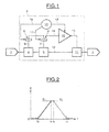
- la figure 1 illustre schématiquement les principaux éléments d'une transmission infiniment variable à deux modes de fonctionnement selon l'invention ;
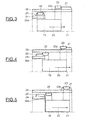
- la figure 2 est un graphe montrant le passage d'un mode de fonctionnement à un autre , et
- les figures 3 à 5 illustrent les différentes positions de l'actionneur unique selon un mode de réalisation, l'ensemble étant vu en coupe schématique et partielle.
- FIG. 1 schematically illustrates the main elements of an infinitely variable transmission with two modes of operation according to the invention;
- FIG. 2 is a graph showing the transition from one operating mode to another, and
- Figures 3 to 5 illustrate the different positions of the single actuator according to one embodiment, the assembly being seen in schematic and partial section.
La figure 1 illustre schématiquement les principaux éléments d'un mode de réalisation d'une transmission selon l'invention. Un moteur thermique 1 constitue un groupe motopropulseur d'un véhicule automobile. L'essieu des roues motrices du véhicule, schématisé par le bloc 2, constitue l'élément entraîné. Entre l'élément entraîné 2 et le moteur thermique 1, est disposée la transmission infiniment variable, référencée 3 dans son ensemble.Figure 1 schematically illustrates the main elements of an embodiment of a transmission according to the invention. A
La transmission 3 comprend deux voies de puissance reliant en parallèle le moteur thermique 1 aux roues 2 du véhicule. Chacune de ces deux voies de puissance comprend un train d'engrenages épicycloïdal diviseur de puissance 4, 5, dont un arbre secondaire 6, 7 peut être bloqué en rotation ou libéré par un dispositif de couplage/découplage 8, 9.The transmission 3 comprises two power paths connecting in parallel the
La transmission comprend également une voie de puissance contenant un variateur de vitesse continu schématisé par la référence 10. Un train d'engrenages épicycloïdal 11 joue le rôle d'un élément rassembleur de puissance de l'ensemble des voies de puissance. A cet effet, les arbres de sortie 12 des trains diviseurs de puissance 4, 5 et l'arbre de sortie 13 du variateur de vitesse 10 sont connectés à l'entrée du train rassembleur de puissance 11.The transmission also comprises a power channel containing a continuous speed variator shown schematically by
Les arbres secondaires 6, 7 des deux trains diviseurs de puissance 4, 5 peuvent être reliés mécaniquement à l'arbre d'entrée 14 du variateur de vitesse 10 lorsque les dispositifs de couplage/découplage 8, 9 sont actionnés, de façon à bloquer en rotation l'un ou l'autre des arbres 6, 7.The
La transmission 3 comprend également un dispositif de commande 15 pour le changement de mode, capable de commander l'actionnement des deux dispositifs de couplage/découplage 8, 9, les voies de commande étant schématisées par les références 16 et 17 sur la figure 1. Le dispositif de commande 15 est également capable de commander par la connexion 18 le variateur de vitesse 10.The transmission 3 also comprises a
Le dispositif de commande 15 de changement de mode est capable de commander, pendant la durée d'un changement de mode, les deux dispositifs de couplage/découplage 8, 9, de façon à faire coexister pendant cette période les deux modes de transmission de puissance.The mode
La figure 2 illustre, par un diagramme temporel, l'état d'engagement E des deux dispositifs de couplage/découplage 8, 9. L'état du dispositif de couplage/découplage 8, référencé E1 sur la figure 2, et l'état du dispositif de couplage/découplage 9, référencé E2 sur la figure 2, sont complémentaires entre les temps t0 et t1, ainsi qu'entre les temps t2 et t3. Au contraire, entre les temps t1 et t2, les deux dispositifs de couplage/découplage 8, 9, dont l'état respectif est E1 et E2, sont simultanément engagés, permettant ainsi de procéder au changement de mode.FIG. 2 illustrates, by a time diagram, the state of engagement E of the two coupling /
Les dispositifs de couplage/découplage 8, 9 peuvent être réalisés de différentes manières.The coupling /
Dans un mode de réalisation préféré, illustré sur les figures 3 à 5, il est prévu un actionneur unique 19, pour les deux dispositifs de couplage/découplage 8, 9 de la figure 1. L'actionneur 19 est du type à crabot et est mobile en translation selon la flèche 20, parallèlement à l'axe 21 des deux arbres de transmission 6, 7, schématiquement indiqués sur la figure 1. L'actionneur 19 présente un premier ensemble de dents de crabot 22 et un deuxième ensemble de dents de crabot 23 axialement décalé par rapport au premier ensemble. L'arbre secondaire 6 est solidaire d'une pièce annulaire 24 qui porte un ensemble de dents de crabot 25 complémentaires des dents de crabot 22 et capables de coopérer avec celles-ci. De la même manière, l'arbre secondaire 7 est solidaire d'un organe annulaire 26 qui porte un ensemble de dents de crabot 27 capables de coopérer avec les dents de crabot 23.In a preferred embodiment, illustrated in FIGS. 3 to 5, there is provided a
On notera que, dans l'exemple illustré, les deux ensembles de dents de crabot 22, 23 sont montés à l'intérieur de deux organes annulaires 22a, 23a solidaires de l'actionneur 19. Les deux ensembles de dents de crabot 25 et 27 sont, quant à eux, disposés à la périphérie extérieure des organes annulaires respectifs 24 et 26.Note that, in the illustrated example, the two sets of
Le dispositif actionneur 19 fonctionne de la manière suivante.The
Sur la figure 3, l'actionneur 19 se trouve dans une première position, dans laquelle les dents de crabot 22 sont en prise avec les dents de crabot 25. Au contraire, les dents de crabot 23 sont complètement dégagées des dents de crabot 27. L'organe annulaire 24 solidaire de l'arbre 6 est donc bloqué en rotation, alors que l'élément annulaire 26 solidaire de l'arbre 7 est libre. Un déplacement en translation rectiligne, dans le sens de la flèche 20 de la figure 3, déplace les deux ensembles de dents de crabot 22, 23 dans la position illustrée sur la figure 4. Dans cette position, compte tenu du décalage axial choisi pour les dents 22 par rapport aux dents 23, il apparaît que les dents de crabot 22 sont en partie en prise avec les dents de crabot 25, tandis que les dents de crabot 23 sont en partie en prise avec les dents de crabot 27. Dans cette position intermédiaire, les deux arbres 6, 7 se trouvent donc bloqués en rotation par l'actionneur 19. Cette position correspond à la phase de changement de mode de la transmission. Les deux modes sont en effet simultanément engagés. Un seul mouvement de translation rectiligne de l'actionneur unique 19 permet ainsi de basculer d'un premier mode à une phase d'engagement simultanée de deux modes.In FIG. 3, the
Une poursuite du mouvement de translation rectiligne dans le sens de la flèche 20 place l'actionneur 19 dans la position illustrée sur la figure 5, dans laquelle les dents de crabot 22 sont dégagées des dents de crabot 25, tandis que les dents de crabot 23 sont engagées avec les dents de crabot 27. Dans cette position, le deuxième mode de la transmission se trouve donc engagé.Continuing the rectilinear translational movement in the direction of the
Le mouvement de translation rectiligne de l'actionneur unique 19 peut être obtenu au moyen d'un dispositif d'actionnement linéaire électrique ou par l'action d'une force hydraulique.The rectilinear translational movement of the
Bien que l'on ait illustré dans cet exemple l'utilisation d'un actionneur muni de dents de crabot, on comprendra qu'il serait possible d'utiliser d'autres types de dispositifs de couplage/découplage, tels que des embrayages, en particulier à commande hydraulique.Although the use of an actuator with dog teeth has been illustrated in this example, it will be understood that it would be possible to use other types of coupling / decoupling devices, such as clutches, in particular hydraulically controlled.
Dans l'exemple illustré, on a indiqué que l'actionneur unique était bloqué en rotation. On comprendra, bien entendu, que l'actionneur puisse également être lié à un autre arbre de la transmission suivant la cinématique choisie.In the illustrated example, it has been indicated that the single actuator is locked in rotation. It will be understood, of course, that the actuator can also be linked to another shaft of the transmission according to the selected kinematics.
Claims (11)
- Infinitely variable power bypass transmission with two operating modes for a motor vehicle fitted with an internal combustion engine, of the type comprising:- at least two power lines connecting in parallel the internal combustion engine to the wheels of the vehicle and each containing a coupling/decoupling device (8, 9) capable of locking or releasing a transmission shaft (6, 7) depending on the operating mode;- a line containing a continuous speed variator (10) ;- and a mode-changing control device (15) capable of controlling the actuation of the coupling/decoupling devices and of simultaneously engaging the two modes while locking the two transmission shafts, during a change of mode;characterized in that it comprises a single actuator (19) for the two coupling/decoupling devices.
- Transmission according to Claim 1, characterized in that the actuator (19) is of the dog clutch type.
- Transmission according to Claims 1 or 2, characterized in that the actuator is driven by a hydraulic force.
- Transmission according to Claims 1 or 2, characterized in that the actuator is driven by an electric force.
- Transmission according to any one of the preceding claims, characterized in that the actuator can be moved in translation parallel to the two transmission shafts.
- Transmission according to any one of the preceding claims, characterized in that the actuator (19) comprises two sets of dog clutch teeth (22, 23) capable of engaging respectively with two sets of matching dog clutch teeth (25, 27) fixedly attached to the two transmission shafts.
- Transmission according to Claim 6, characterized in that the two sets of dog clutch teeth of the actuator are axially offset from one another so as to be able to interact simultaneously with the matching sets of dog clutch teeth of the two transmission shafts in one position of the actuator and to be able to interact alternately with one of the matching sets of dog clutch teeth of the two transmission shafts in other positions of the actuator.
- Transmission according to any one of the preceding claims, characterized in that the continuous speed variator (10) is of the electric type.
- Transmission according to Claim 8, characterized in that the speed variator comprises two traction electric machines or one traction electric machine and one variator electric motor, particularly for producing a hybrid power plant.
- Transmission according to any one of the preceding claims, characterized in that the two power lines each comprise a power dividing epicyclic gear train (4, 5) of which one member is connected to one of the coupling/decoupling devices.
- Transmission according to Claim 10, characterized in that it comprises a power combining epicyclic gear train (11) comprising an output shaft connected to the wheels of the vehicle, the output shafts of the power dividing trains and of the speed variator being connected to the input of said combining train.
Applications Claiming Priority (2)
| Application Number | Priority Date | Filing Date | Title |
|---|---|---|---|
| FR0404173A FR2868995B1 (en) | 2004-04-20 | 2004-04-20 | INFINITELY VARIABLE POWER-DERIVED TRANSMISSION WITH TWO OPERATING MODES FOR MOTOR VEHICLE |
| PCT/FR2005/050249 WO2005105502A1 (en) | 2004-04-20 | 2005-04-15 | Infinitely variable power bypass transmission with two operating modes for a motor vehicle |
Publications (2)
| Publication Number | Publication Date |
|---|---|
| EP1740407A1 EP1740407A1 (en) | 2007-01-10 |
| EP1740407B1 true EP1740407B1 (en) | 2007-08-22 |
Family
ID=34945439
Family Applications (1)
| Application Number | Title | Priority Date | Filing Date |
|---|---|---|---|
| EP05746987A Expired - Lifetime EP1740407B1 (en) | 2004-04-20 | 2005-04-15 | Infinitely variable power bypass transmission with two operating modes for a motor vehicle |
Country Status (7)
| Country | Link |
|---|---|
| US (1) | US9085227B2 (en) |
| EP (1) | EP1740407B1 (en) |
| JP (1) | JP4812753B2 (en) |
| AT (1) | ATE370858T1 (en) |
| DE (1) | DE602005002135T2 (en) |
| FR (1) | FR2868995B1 (en) |
| WO (1) | WO2005105502A1 (en) |
Families Citing this family (8)
| Publication number | Priority date | Publication date | Assignee | Title |
|---|---|---|---|---|
| FR2870910B1 (en) * | 2004-05-26 | 2006-08-04 | Renault Sas | INFINITELY VARIABLE POWER-DERIVED TRANSMISSION WITH TWO OPERATING MODES CONTROLLED BY A CRABOT GAUGE FOR A MOTOR VEHICLE |
| DE102005062869A1 (en) * | 2005-12-29 | 2007-07-05 | Robert Bosch Gmbh | Motor vehicle`s hybrid drive controlling method, involves carrying out torque comparison between allowable torque and additional torque, and comparing allowable torque with reference torques for two individual drives of hybrid drive |
| US8000865B2 (en) * | 2008-05-06 | 2011-08-16 | GM Global Technology Operations LLC | Method and apparatus for transitioning an electrically variable transmission |
| SE539659C2 (en) | 2014-05-27 | 2017-10-24 | Scania Cv Ab | Transmission for vehicles and vehicles which include such a gearbox |
| WO2015183159A1 (en) * | 2014-05-27 | 2015-12-03 | Scania Cv Ab | Gearbox for vehicles and vehicles comprising such a gearbox |
| US10920730B2 (en) * | 2019-04-16 | 2021-02-16 | Deere & Company | Multi-mode integrated starter-generator device with dog clutch arrangement |
| JP2021088312A (en) * | 2019-12-05 | 2021-06-10 | トヨタ自動車株式会社 | Control device for power transmission device |
| KR20230151122A (en) | 2022-04-22 | 2023-11-01 | 현대자동차주식회사 | Hybrid electric vehicle and method of shift control for the same |
Family Cites Families (21)
| Publication number | Priority date | Publication date | Assignee | Title |
|---|---|---|---|---|
| JPH04282052A (en) * | 1991-03-07 | 1992-10-07 | Toyota Motor Corp | Driving force transmission device |
| US5558589A (en) | 1995-07-20 | 1996-09-24 | General Motors Corporation | Two-mode, compound-split, electro-mechanical vehicular transmission |
| JP3336951B2 (en) * | 1998-04-28 | 2002-10-21 | 株式会社日立製作所 | Automotive power transmission |
| US5935035A (en) * | 1998-06-24 | 1999-08-10 | General Motors Corporation | Electro-mechanical powertrain |
| JP3668830B2 (en) * | 1998-08-28 | 2005-07-06 | トヨタ自動車株式会社 | Power transmission device and hybrid vehicle using the same |
| DE19858553A1 (en) * | 1998-12-18 | 2000-06-21 | Zahnradfabrik Friedrichshafen | Infinitely-variable automotive gear reduces the load on the variator through the whole speed range, minimises noise and manufacturing costs |
| JP3449277B2 (en) * | 1999-02-05 | 2003-09-22 | 株式会社日立製作所 | Hybrid vehicle and control device thereof |
| US7185722B1 (en) * | 2000-02-04 | 2007-03-06 | Hitachi, Ltd. | Power transmission apparatus of motor vehicles |
| JP2003522670A (en) * | 2000-02-15 | 2003-07-29 | ルーク ラメレン ウント クツプルングスバウ ベタイリグングス コマンディートゲゼルシャフト | transmission |
| JP3569210B2 (en) * | 2000-08-11 | 2004-09-22 | 本田技研工業株式会社 | Power transmission device for hybrid vehicle and control method therefor |
| DE10062556A1 (en) * | 2000-12-15 | 2002-07-04 | Bosch Gmbh Robert | Method for operating a motor vehicle driven by an internal combustion engine and two electric machines |
| FR2818346B1 (en) * | 2000-12-18 | 2003-03-21 | Renault | INFINITELY VARIABLE POWER-DRIVEN TRANSMISSION |
| FR2823156B1 (en) * | 2001-04-06 | 2003-08-01 | Renault Sas | INFINITELY VARIABLE POWER-BASED TRANSMISSION WITH TWO OPERATING MODES |
| FR2823281B1 (en) * | 2001-04-09 | 2003-06-27 | Renault Sas | MULTI-MODES TRANSMISSION DEVICE AND VEHICLE USING SUCH A DEVICE |
| FR2827339B1 (en) * | 2001-07-12 | 2005-11-11 | Renault | DEVICE FOR CONTROLLING THE OPERATING POINT OF THE POWER UNIT OF A VEHICLE |
| US6540631B2 (en) * | 2001-08-13 | 2003-04-01 | General Motors Corporation | Electrically variable transmission with variable input power split and independent shifting |
| EP1507991B1 (en) * | 2002-05-28 | 2006-10-11 | Torotrak (Development) Limited | Continuously variable ratio transmission system |
| FR2847321B1 (en) | 2002-11-14 | 2005-09-02 | Renault Sa | INFINITELY VARIABLE TRANSMISSION WITH ELECTRIC VARIATOR AND TWO COMPOUND TRAINS |
| US6945894B2 (en) * | 2003-10-29 | 2005-09-20 | General Motors Corporation | Two range electrically variable power transmission |
| US7048667B2 (en) * | 2004-02-09 | 2006-05-23 | Ford Global Technologies, Llc | Power split transaxle for producing stepless reverse, forward and geared neutral speed ratios |
| US7214156B2 (en) * | 2004-06-18 | 2007-05-08 | Eaton Corporation | Start and operation sequences for hybrid motor vehicles |
-
2004
- 2004-04-20 FR FR0404173A patent/FR2868995B1/en not_active Expired - Fee Related
-
2005
- 2005-04-15 AT AT05746987T patent/ATE370858T1/en not_active IP Right Cessation
- 2005-04-15 DE DE602005002135T patent/DE602005002135T2/en not_active Expired - Lifetime
- 2005-04-15 EP EP05746987A patent/EP1740407B1/en not_active Expired - Lifetime
- 2005-04-15 JP JP2007508948A patent/JP4812753B2/en not_active Expired - Fee Related
- 2005-04-15 WO PCT/FR2005/050249 patent/WO2005105502A1/en not_active Ceased
- 2005-04-15 US US11/578,973 patent/US9085227B2/en not_active Expired - Fee Related
Also Published As
| Publication number | Publication date |
|---|---|
| FR2868995B1 (en) | 2007-06-29 |
| JP2007533933A (en) | 2007-11-22 |
| DE602005002135T2 (en) | 2008-07-31 |
| FR2868995A1 (en) | 2005-10-21 |
| US9085227B2 (en) | 2015-07-21 |
| DE602005002135D1 (en) | 2007-10-04 |
| ATE370858T1 (en) | 2007-09-15 |
| EP1740407A1 (en) | 2007-01-10 |
| JP4812753B2 (en) | 2011-11-09 |
| US20070221432A1 (en) | 2007-09-27 |
| WO2005105502A1 (en) | 2005-11-10 |
Similar Documents
| Publication | Publication Date | Title |
|---|---|---|
| EP2196707B1 (en) | Shifting apparatus for dual clutch transmission | |
| JP5705117B2 (en) | Crank / CVT / Transmission | |
| FR2765839A1 (en) | Transmission with energy storage and ancillary drives | |
| EP1753986B1 (en) | Infinitely-variable transmission with double mode power transmission controlled by a sliding dog for a motor vehicle | |
| EP1977140A1 (en) | Drive train comprising an auxiliary engine which is connected to a countershaft of the transmission | |
| FR2816554A1 (en) | VEHICLE TRANSMISSION SYSTEM AND SPEED CHANGE DEVICE FOR SUCH TRANSMISSION | |
| EP1740407B1 (en) | Infinitely variable power bypass transmission with two operating modes for a motor vehicle | |
| FR2946291A1 (en) | Power train for electric propulsion vehicle, has electric machine, which drives wheels of vehicle on distinct ratio by speed changing mechanism, where ratios are obtained by engaging fixed pins with idly-rotating pinions on secondary shaft | |
| FR2862363A1 (en) | MULTI-REPORTING TRANSMISSION DEVICE, IN PARTICULAR FOR THE AUTOMOBILE | |
| FR2946293A1 (en) | MOTOR POWERTRAIN FOR THREE-TREE ELECTRIC VEHICLES FOR OBTAINING TWO TRANSMISSION REPORTS | |
| US9885416B2 (en) | Transmission assembly for a self-propelled machine, of the type that can be positioned between the primary motor shaft and the wheels of said machine | |
| FR2774447A1 (en) | Vehicle with automatic transmission operation device | |
| WO2008104693A1 (en) | Mode changing device for a power branching transmission | |
| WO2010007291A1 (en) | Hybrid gearbox with parallel shafts | |
| FR2892082A1 (en) | TRANSMISSION, ESPECIALLY BETWEEN A MOTOR SHAFT AND A WHEEL DRIVE SHAFT OF AN ENGINE, A MOTOR PREFERABLY EQUIPPED WITH SUCH A TRANSMISSION AND ITS CONTROL METHOD IN OPERATION | |
| WO2005025910A1 (en) | Infinitely-variable power-branching transmission with two operating modes, comprising three planetary trains | |
| CN110834531B (en) | Power split transmission | |
| EP3842666B1 (en) | Electric powertrain with two clutches | |
| WO2007093727A2 (en) | Method for blocking a drive train of a motor vehicle and for controlling an automatic gearbox comprising a corresponding selection grid | |
| FR2946292A3 (en) | Power train for motor vehicle, has electrical machine for driving wheels of motor vehicle by speed changing mechanism, and input clutches intercalated between electrical machine and speed changing mechanism | |
| FR2912795A1 (en) | Power distribution transmission actuator for motor vehicle, has helical part transforming rotational movement of hub between central and angular positions into translational movement of driving body along axle, where body is immovable | |
| FR2896564A1 (en) | ROBOTIZED GEARBOX WITH TWO ACTUATORS. | |
| FR2819570A1 (en) | GEARBOX WITH ROBOTIZED CONTROL OF MOTOR VEHICLE AND METHOD FOR MANAGING AN ELECTRONIC CONTROL UNIT OF SUCH A GEARBOX | |
| FR2800826A1 (en) | Motor vehicle drive transmission has variator for power drive with epicyclic train forming cross shaft between wheels | |
| US20150298703A1 (en) | Transmission assembly for a self-propelled machine, and machine fitted with such a transmission |
Legal Events
| Date | Code | Title | Description |
|---|---|---|---|
| PUAI | Public reference made under article 153(3) epc to a published international application that has entered the european phase |
Free format text: ORIGINAL CODE: 0009012 |
|
| 17P | Request for examination filed |
Effective date: 20061120 |
|
| AK | Designated contracting states |
Kind code of ref document: A1 Designated state(s): AT BE BG CH CY CZ DE DK EE ES FI FR GB GR HU IE IS IT LI LT LU MC NL PL PT RO SE SI SK TR |
|
| GRAP | Despatch of communication of intention to grant a patent |
Free format text: ORIGINAL CODE: EPIDOSNIGR1 |
|
| RIN1 | Information on inventor provided before grant (corrected) |
Inventor name: PICHON, YVES Inventor name: FOURNIER, VINCENT |
|
| GRAS | Grant fee paid |
Free format text: ORIGINAL CODE: EPIDOSNIGR3 |
|
| GRAA | (expected) grant |
Free format text: ORIGINAL CODE: 0009210 |
|
| DAX | Request for extension of the european patent (deleted) | ||
| AK | Designated contracting states |
Kind code of ref document: B1 Designated state(s): AT BE BG CH CY CZ DE DK EE ES FI FR GB GR HU IE IS IT LI LT LU MC NL PL PT RO SE SI SK TR |
|
| REG | Reference to a national code |
Ref country code: GB Ref legal event code: FG4D Free format text: NOT ENGLISH |
|
| REG | Reference to a national code |
Ref country code: CH Ref legal event code: EP |
|
| REG | Reference to a national code |
Ref country code: IE Ref legal event code: FG4D Free format text: LANGUAGE OF EP DOCUMENT: FRENCH |
|
| REF | Corresponds to: |
Ref document number: 602005002135 Country of ref document: DE Date of ref document: 20071004 Kind code of ref document: P |
|
| GBT | Gb: translation of ep patent filed (gb section 77(6)(a)/1977) |
Effective date: 20070927 |
|
| PG25 | Lapsed in a contracting state [announced via postgrant information from national office to epo] |
Ref country code: LT Free format text: LAPSE BECAUSE OF FAILURE TO SUBMIT A TRANSLATION OF THE DESCRIPTION OR TO PAY THE FEE WITHIN THE PRESCRIBED TIME-LIMIT Effective date: 20070822 Ref country code: FI Free format text: LAPSE BECAUSE OF FAILURE TO SUBMIT A TRANSLATION OF THE DESCRIPTION OR TO PAY THE FEE WITHIN THE PRESCRIBED TIME-LIMIT Effective date: 20070822 Ref country code: ES Free format text: LAPSE BECAUSE OF FAILURE TO SUBMIT A TRANSLATION OF THE DESCRIPTION OR TO PAY THE FEE WITHIN THE PRESCRIBED TIME-LIMIT Effective date: 20071203 Ref country code: NL Free format text: LAPSE BECAUSE OF FAILURE TO SUBMIT A TRANSLATION OF THE DESCRIPTION OR TO PAY THE FEE WITHIN THE PRESCRIBED TIME-LIMIT Effective date: 20070822 Ref country code: IS Free format text: LAPSE BECAUSE OF FAILURE TO SUBMIT A TRANSLATION OF THE DESCRIPTION OR TO PAY THE FEE WITHIN THE PRESCRIBED TIME-LIMIT Effective date: 20071222 |
|
| NLV1 | Nl: lapsed or annulled due to failure to fulfill the requirements of art. 29p and 29m of the patents act | ||
| PG25 | Lapsed in a contracting state [announced via postgrant information from national office to epo] |
Ref country code: PL Free format text: LAPSE BECAUSE OF FAILURE TO SUBMIT A TRANSLATION OF THE DESCRIPTION OR TO PAY THE FEE WITHIN THE PRESCRIBED TIME-LIMIT Effective date: 20070822 Ref country code: AT Free format text: LAPSE BECAUSE OF FAILURE TO SUBMIT A TRANSLATION OF THE DESCRIPTION OR TO PAY THE FEE WITHIN THE PRESCRIBED TIME-LIMIT Effective date: 20070822 |
|
| REG | Reference to a national code |
Ref country code: IE Ref legal event code: FD4D |
|
| PG25 | Lapsed in a contracting state [announced via postgrant information from national office to epo] |
Ref country code: DK Free format text: LAPSE BECAUSE OF FAILURE TO SUBMIT A TRANSLATION OF THE DESCRIPTION OR TO PAY THE FEE WITHIN THE PRESCRIBED TIME-LIMIT Effective date: 20070822 Ref country code: GR Free format text: LAPSE BECAUSE OF FAILURE TO SUBMIT A TRANSLATION OF THE DESCRIPTION OR TO PAY THE FEE WITHIN THE PRESCRIBED TIME-LIMIT Effective date: 20071123 |
|
| PG25 | Lapsed in a contracting state [announced via postgrant information from national office to epo] |
Ref country code: PT Free format text: LAPSE BECAUSE OF FAILURE TO SUBMIT A TRANSLATION OF THE DESCRIPTION OR TO PAY THE FEE WITHIN THE PRESCRIBED TIME-LIMIT Effective date: 20080122 Ref country code: SK Free format text: LAPSE BECAUSE OF FAILURE TO SUBMIT A TRANSLATION OF THE DESCRIPTION OR TO PAY THE FEE WITHIN THE PRESCRIBED TIME-LIMIT Effective date: 20070822 Ref country code: IE Free format text: LAPSE BECAUSE OF FAILURE TO SUBMIT A TRANSLATION OF THE DESCRIPTION OR TO PAY THE FEE WITHIN THE PRESCRIBED TIME-LIMIT Effective date: 20070822 Ref country code: CZ Free format text: LAPSE BECAUSE OF FAILURE TO SUBMIT A TRANSLATION OF THE DESCRIPTION OR TO PAY THE FEE WITHIN THE PRESCRIBED TIME-LIMIT Effective date: 20070822 |
|
| PLBE | No opposition filed within time limit |
Free format text: ORIGINAL CODE: 0009261 |
|
| STAA | Information on the status of an ep patent application or granted ep patent |
Free format text: STATUS: NO OPPOSITION FILED WITHIN TIME LIMIT |
|
| PG25 | Lapsed in a contracting state [announced via postgrant information from national office to epo] |
Ref country code: RO Free format text: LAPSE BECAUSE OF FAILURE TO SUBMIT A TRANSLATION OF THE DESCRIPTION OR TO PAY THE FEE WITHIN THE PRESCRIBED TIME-LIMIT Effective date: 20070822 Ref country code: SE Free format text: LAPSE BECAUSE OF FAILURE TO SUBMIT A TRANSLATION OF THE DESCRIPTION OR TO PAY THE FEE WITHIN THE PRESCRIBED TIME-LIMIT Effective date: 20071122 |
|
| 26N | No opposition filed |
Effective date: 20080526 |
|
| BERE | Be: lapsed |
Owner name: RENAULT S.A.S. Effective date: 20080430 |
|
| PG25 | Lapsed in a contracting state [announced via postgrant information from national office to epo] |
Ref country code: MC Free format text: LAPSE BECAUSE OF NON-PAYMENT OF DUE FEES Effective date: 20080430 |
|
| PG25 | Lapsed in a contracting state [announced via postgrant information from national office to epo] |
Ref country code: EE Free format text: LAPSE BECAUSE OF FAILURE TO SUBMIT A TRANSLATION OF THE DESCRIPTION OR TO PAY THE FEE WITHIN THE PRESCRIBED TIME-LIMIT Effective date: 20070822 |
|
| PG25 | Lapsed in a contracting state [announced via postgrant information from national office to epo] |
Ref country code: BE Free format text: LAPSE BECAUSE OF NON-PAYMENT OF DUE FEES Effective date: 20080430 |
|
| PG25 | Lapsed in a contracting state [announced via postgrant information from national office to epo] |
Ref country code: SI Free format text: LAPSE BECAUSE OF FAILURE TO SUBMIT A TRANSLATION OF THE DESCRIPTION OR TO PAY THE FEE WITHIN THE PRESCRIBED TIME-LIMIT Effective date: 20070822 |
|
| PG25 | Lapsed in a contracting state [announced via postgrant information from national office to epo] |
Ref country code: CY Free format text: LAPSE BECAUSE OF FAILURE TO SUBMIT A TRANSLATION OF THE DESCRIPTION OR TO PAY THE FEE WITHIN THE PRESCRIBED TIME-LIMIT Effective date: 20070822 |
|
| REG | Reference to a national code |
Ref country code: CH Ref legal event code: PL |
|
| PG25 | Lapsed in a contracting state [announced via postgrant information from national office to epo] |
Ref country code: LI Free format text: LAPSE BECAUSE OF NON-PAYMENT OF DUE FEES Effective date: 20090430 Ref country code: CH Free format text: LAPSE BECAUSE OF NON-PAYMENT OF DUE FEES Effective date: 20090430 |
|
| PG25 | Lapsed in a contracting state [announced via postgrant information from national office to epo] |
Ref country code: HU Free format text: LAPSE BECAUSE OF FAILURE TO SUBMIT A TRANSLATION OF THE DESCRIPTION OR TO PAY THE FEE WITHIN THE PRESCRIBED TIME-LIMIT Effective date: 20080223 Ref country code: LU Free format text: LAPSE BECAUSE OF NON-PAYMENT OF DUE FEES Effective date: 20080415 |
|
| PG25 | Lapsed in a contracting state [announced via postgrant information from national office to epo] |
Ref country code: TR Free format text: LAPSE BECAUSE OF FAILURE TO SUBMIT A TRANSLATION OF THE DESCRIPTION OR TO PAY THE FEE WITHIN THE PRESCRIBED TIME-LIMIT Effective date: 20070822 |
|
| PG25 | Lapsed in a contracting state [announced via postgrant information from national office to epo] |
Ref country code: BG Free format text: LAPSE BECAUSE OF FAILURE TO SUBMIT A TRANSLATION OF THE DESCRIPTION OR TO PAY THE FEE WITHIN THE PRESCRIBED TIME-LIMIT Effective date: 20070822 |
|
| PG25 | Lapsed in a contracting state [announced via postgrant information from national office to epo] |
Ref country code: IT Free format text: LAPSE BECAUSE OF NON-PAYMENT OF DUE FEES Effective date: 20080430 |
|
| REG | Reference to a national code |
Ref country code: FR Ref legal event code: PLFP Year of fee payment: 11 |
|
| PGFP | Annual fee paid to national office [announced via postgrant information from national office to epo] |
Ref country code: DE Payment date: 20150421 Year of fee payment: 11 Ref country code: GB Payment date: 20150420 Year of fee payment: 11 |
|
| PGFP | Annual fee paid to national office [announced via postgrant information from national office to epo] |
Ref country code: FR Payment date: 20150421 Year of fee payment: 11 |
|
| REG | Reference to a national code |
Ref country code: DE Ref legal event code: R119 Ref document number: 602005002135 Country of ref document: DE |
|
| GBPC | Gb: european patent ceased through non-payment of renewal fee |
Effective date: 20160415 |
|
| REG | Reference to a national code |
Ref country code: FR Ref legal event code: ST Effective date: 20161230 |
|
| PG25 | Lapsed in a contracting state [announced via postgrant information from national office to epo] |
Ref country code: FR Free format text: LAPSE BECAUSE OF NON-PAYMENT OF DUE FEES Effective date: 20160502 Ref country code: GB Free format text: LAPSE BECAUSE OF NON-PAYMENT OF DUE FEES Effective date: 20160415 Ref country code: DE Free format text: LAPSE BECAUSE OF NON-PAYMENT OF DUE FEES Effective date: 20161101 |