EP1740293B1 - A homogeniser for the continuous treatment of fluids at very high pressure - Google Patents
A homogeniser for the continuous treatment of fluids at very high pressure Download PDFInfo
- Publication number
- EP1740293B1 EP1740293B1 EP04769899A EP04769899A EP1740293B1 EP 1740293 B1 EP1740293 B1 EP 1740293B1 EP 04769899 A EP04769899 A EP 04769899A EP 04769899 A EP04769899 A EP 04769899A EP 1740293 B1 EP1740293 B1 EP 1740293B1
- Authority
- EP
- European Patent Office
- Prior art keywords
- homogeniser
- seal
- delivery
- plunger
- manifold
- Prior art date
- Legal status (The legal status is an assumption and is not a legal conclusion. Google has not performed a legal analysis and makes no representation as to the accuracy of the status listed.)
- Expired - Lifetime
Links
- 239000012530 fluid Substances 0.000 title claims abstract description 21
- 230000006835 compression Effects 0.000 claims abstract description 26
- 238000007906 compression Methods 0.000 claims abstract description 26
- 238000011144 upstream manufacturing Methods 0.000 claims abstract description 6
- 238000001125 extrusion Methods 0.000 claims description 10
- 230000003068 static effect Effects 0.000 claims description 9
- 239000000463 material Substances 0.000 claims description 6
- 239000004696 Poly ether ether ketone Substances 0.000 claims description 4
- 229910052581 Si3N4 Inorganic materials 0.000 claims description 4
- JUPQTSLXMOCDHR-UHFFFAOYSA-N benzene-1,4-diol;bis(4-fluorophenyl)methanone Chemical compound OC1=CC=C(O)C=C1.C1=CC(F)=CC=C1C(=O)C1=CC=C(F)C=C1 JUPQTSLXMOCDHR-UHFFFAOYSA-N 0.000 claims description 4
- 230000001050 lubricating effect Effects 0.000 claims description 4
- 229920002530 polyetherether ketone Polymers 0.000 claims description 4
- 239000004033 plastic Substances 0.000 claims description 3
- 229920003023 plastic Polymers 0.000 claims description 3
- 229910010293 ceramic material Inorganic materials 0.000 claims description 2
- 229920001971 elastomer Polymers 0.000 claims description 2
- 239000000806 elastomer Substances 0.000 claims description 2
- 238000000605 extraction Methods 0.000 claims description 2
- 238000005498 polishing Methods 0.000 claims description 2
- 238000007789 sealing Methods 0.000 claims description 2
- 238000005480 shot peening Methods 0.000 claims description 2
- HQVNEWCFYHHQES-UHFFFAOYSA-N silicon nitride Chemical compound N12[Si]34N5[Si]62N3[Si]51N64 HQVNEWCFYHHQES-UHFFFAOYSA-N 0.000 claims description 2
- 229910001220 stainless steel Inorganic materials 0.000 claims description 2
- 239000010935 stainless steel Substances 0.000 claims description 2
- 239000002826 coolant Substances 0.000 claims 1
- 239000007788 liquid Substances 0.000 description 4
- 239000000126 substance Substances 0.000 description 4
- 238000005086 pumping Methods 0.000 description 3
- 238000004519 manufacturing process Methods 0.000 description 2
- 238000000034 method Methods 0.000 description 2
- 230000001413 cellular effect Effects 0.000 description 1
- 239000002537 cosmetic Substances 0.000 description 1
- 238000011161 development Methods 0.000 description 1
- 239000003814 drug Substances 0.000 description 1
- 239000000839 emulsion Substances 0.000 description 1
- 230000002255 enzymatic effect Effects 0.000 description 1
- 238000002474 experimental method Methods 0.000 description 1
- 238000003780 insertion Methods 0.000 description 1
- 230000037431 insertion Effects 0.000 description 1
- 238000009533 lab test Methods 0.000 description 1
- 238000012423 maintenance Methods 0.000 description 1
- 229920002635 polyurethane Polymers 0.000 description 1
- 239000004814 polyurethane Substances 0.000 description 1
- 238000002360 preparation method Methods 0.000 description 1
- 238000011160 research Methods 0.000 description 1
- 238000004088 simulation Methods 0.000 description 1
- 230000001225 therapeutic effect Effects 0.000 description 1
- 229960005486 vaccine Drugs 0.000 description 1
- XLYOFNOQVPJJNP-UHFFFAOYSA-N water Substances O XLYOFNOQVPJJNP-UHFFFAOYSA-N 0.000 description 1
Images

Classifications
-
- F—MECHANICAL ENGINEERING; LIGHTING; HEATING; WEAPONS; BLASTING
- F04—POSITIVE - DISPLACEMENT MACHINES FOR LIQUIDS; PUMPS FOR LIQUIDS OR ELASTIC FLUIDS
- F04B—POSITIVE-DISPLACEMENT MACHINES FOR LIQUIDS; PUMPS
- F04B53/00—Component parts, details or accessories not provided for in, or of interest apart from, groups F04B1/00 - F04B23/00 or F04B39/00 - F04B47/00
- F04B53/16—Casings; Cylinders; Cylinder liners or heads; Fluid connections
- F04B53/162—Adaptations of cylinders
- F04B53/164—Stoffing boxes
-
- B—PERFORMING OPERATIONS; TRANSPORTING
- B01—PHYSICAL OR CHEMICAL PROCESSES OR APPARATUS IN GENERAL
- B01F—MIXING, e.g. DISSOLVING, EMULSIFYING OR DISPERSING
- B01F25/00—Flow mixers; Mixers for falling materials, e.g. solid particles
- B01F25/105—Mixing heads, i.e. compact mixing units or modules, using mixing valves for feeding and mixing at least two components
Definitions
- the present invention relates to a homogeniser for the continuous treatment of fluids at very high pressure.
- Said apparatus consisting of a plunger pump and of one or more homogenising valves installed in series on the delivery manifold, is applied in sectors such as the food, pharmaceuticals, cosmetics, and chemical industries and is used more generally for cell breakage treatment of fluids, that is to say for biological products such as vaccines, therapeutic substances and enzymatic and diagnostic preparations.
- the objective of all cell breakage techniques is to achieve productive cell disaggregation, that is to say which destroys any polluting cells, and at the same time is able to liberate any subcellular substances useful for subsequent production processes.
- a high pressure homogeniser which is normal in mechanical cell breakage techniques, takes advantage of the forced passage from a high pressure zone to a low pressure zone, causing said controlled cellular disaggregation of the fluid treated, using an adjustable valve, commonly known as a homogenising valve, applied on the plunger pump delivery side to generate the pressure required.
- PR99A000045 by the same Applicant describes a pump for the treatment of fluids at high pressure comprising a reciprocating plunger in a compression chamber from a fluid intake position to a fluid delivery position; a block for each plunger, connecting the pumping chamber to the intake and delivery valves housed in lateral containers fixed to the block.
- Each block comprises two half-parts or plates clamped together and having internal grooves to house an internal manifold which connects the pumping chamber and the intake and delivery valves.
- the prior art comprises various different types of pumps and therefore homogenisers able to operate at pressures which range from around 500 bar to a maximum of 1500 bar.
- US 6 305 265 B1 describes also a pump adapted to work at very high pressures.
- the Applicant analysed the assembly consisting of the compression chamber, intake pipe and delivery pipe, the pump and the homogenising valve which together form a high pressure homogeniser.
- the aim of the present invention is to provide a homogeniser with a configuration which allows it to reach pressures of up to 4000 bar, the materials used to construct the part subject to the processed fluid pressure being the same.
- Another aim of the present invention is to provide a homogeniser able to operate at up to 4000 bar without increasing its production costs for the maker and maintenance costs for the end user.
- the homogeniser consists of a pump part comprising at least one reciprocating plunger in a compression chamber between a fluid intake position and a fluid delivery position; a block for each plunger, connecting the compression chamber to the intake and delivery valves housed in containers preferably having a cylindrical shape connected to the upper and lower parts of the block by removable connecting systems such as stud bolts; an internal manifold connecting the compression chamber to the intake and delivery valves, the homogeniser being characterised in that, close to the manifold, the plunger has a dynamic self-energising seal system acting on its cylindrical surface, and in that upstream and downstream of each valve, and downstream of the manifold where the manifold intersects with the compression chamber, and generally in the connections between the various component parts of the assembly, there are static seal systems consisting of an anti-extrusion ring in which a self-energising seal with the appropriate geometry and profile is inserted.
- the delivery valve units if more than one, there always being the same number as the plungers, are connected to one another by a delivery manifold which receives the flow of pressurised liquid from each compression chamber.
- the equivalent intake valve units if more than one, are connected to one another by an intake manifold, and there may be a support flange for each intake valve unit inserted between them.
- the numeral 1 denotes as a whole a homogeniser whose body 2 houses a cross-head guide piston 3, driven in a substantially known way, to the end of which a clamp 4 fixes a reciprocating plunger 5 in a compression chamber or cylinder 6.
- the plunger 5 is preferably made of a ceramic material such as pure silicon nitride Si 3 N 4 .
- the compression chamber 6 is formed inside a first block 7 to which stud bolts 8 fix a housing flange 9 and a locking flange 10, the latter both preferably cylindrical and between them forming a guide chamber 11 for the plunger 5 coaxial with the compression chamber 6 ( Figure 2).
- the block 7 and the housing flange 9 have, on their surfaces which face one another, a plurality of cylindrical connecting and centring pins 12, whilst the locking flange 10 has, on the surface facing the housing flange 9 a projection 13 having the shape of a truncated cylinder designed to fit into a recess in the surface of the housing flange 9.
- a seat 14 formed by a widening of the cross-section of the guide chamber 11 hole, for housing a guide bushing 15 for the plunger 5, made of self-lubricating plastic material, preferably PEEK, and having one end 15a in contact with the widening of the cross-section of the guide chamber 11 hole and the opposite end 15b clamped by an elastic stop ring 16.
- Said guide bushing 15 is preferably characterised by two or more longitudinal cuts designed to reduce the contact surface between the bushing 15 and the plunger 5 to limit friction and allow evacuation of the lubricating liquid used from a lubricating liquid feed pipe 17, present on the locking flange 10 and preferably angled so that it is perpendicular to a horizontal plane passing through the axis of the guide chamber 11 and parallel with the surface of the locking flange 10 in contact with the housing flange 9.
- Said lubricating pipe 17, supplied with water or another type of liquid or emulsion, has one end 17a opening into the plunger 5 guide chamber 11 and the opposite end 17b terminating on the side wall of the locking flange 10.
- the first widening of the cross-section 18 involves the insertion of a first dynamic seal unit 21 acting on the surface of the reciprocating plunger 5, having a first self-energising seal 22, preferably shaped so that it has a single sealing lip and preferably made of a combination of plastic materials such as high molecular weight PE and
- the first self-energising seal and a bearing assembly 23 face one another and are respectively closed upstream of the first self-energising seal 22 by the shoulder 20 and downstream of the bearing assembly 23 by the projection 13 on the locking flange 10.
- the projection 13 is used to centre the PEEK bushing 15 relative to the housing flange 9.
- the bearing assembly 23 is made of special non-galling stainless steel, preferably Nitronic 60, and is coaxial with and alongside the first self-energising seal 22 and equipped with a system for extraction from its housing such as a suitably sized thread.
- the second widening of the cross-section 19 houses a second static seal unit 24 having a second self-energising seal 25 (with dimensions and geometry allowing containment of the very high pressures and preferably made of polyurethane with Shore hardness 90-98), blocked upstream of it by the surface of the block 7 and downstream of it by the shoulder 20.
- the seal 25 does not make contact with the plunger 5 and is designed to contain the pressurised fluid between the block 7 and the chamber 6; it may also be fitted with an external anti-extrusion ring 39.
- the numeral 26 denotes a block consisting of two half-parts or plates 26a and 26b rigidly clamped to one another by fixing means, preferably stud bolts not illustrated in Figure 1.
- the insides of the two plates 26a and 26b have been machined to make grooves in them designed to house an internal manifold 27, preferably having a hemispherical shape, connecting the compression chamber 6 and a non-return intake valve 28 and a non-return delivery valve 29 housed in containers 30 inserted between the central blocks 26 and respectively the delivery manifold 40 and the lower support flanges 41.
- the block 26 may also consist of a single piece, directly worked with a machine tool to create the channels 31 and 32 and the manifold hole 27 opposite the rear surface of the block 26.
- the non-return intake valve 28 is connected to the internal manifold 27 by the channel 31 which forms an intake pipe and the non-return delivery valve 29 is connected to the internal manifold 27 by the channel 32 which forms a delivery pipe.
- the intake pipe and delivery pipe are arranged in such a way that they are specular with one another relative to a horizontal plane passing through the axis of the pumping chamber 6 and set at an angle ⁇ to the normal to said horizontal plane which varies from 45 to 62 degrees, preferably 56 degrees.
- the internal surfaces of the manifold 27 and of the intake and delivery pipes 31 and 32, exposed to the pressure of the fluid, are treated by polishing, radiusing of any edges on the intersections of concurrent holes, micro shot peening and electropolishing.
- Said hollows 33, 34 are designed to accommodate a third static seal unit 35 having an anti-extrusion ring 36, preferably a circular ring with a rectangular cross-section, inside which a third self-energising seal 37 is fitted.
- Said third static seal unit 35 is also inserted, by means of a third hollow 38, close to the internal manifold 27, more precisely at the intersection between the manifold and the compression chamber 6 ( Figure 3).
- the third static seal unit 35 has one end closed by the block 7 and the opposite end contained in a widening of the cross-section of the internal manifold 27.
- Each anti-extrusion ring 36 is shaped in such a way as to create an interference fit with the height of the respective hollow 33, 34, 38, preferably by 0.1 mm, so that, during assembly, the ring forms a mechanical seal on the hollow and at the same time guarantees correct self-energising seal 37 preloading.
- the numeral 40 denotes a delivery manifold connecting the two or more delivery valve 29 units, whilst 41 denotes a support flange for the intake valve 28 unit for each plunger connected to the pump intake manifold.
Landscapes
- Engineering & Computer Science (AREA)
- Chemical & Material Sciences (AREA)
- Chemical Kinetics & Catalysis (AREA)
- Mechanical Engineering (AREA)
- General Engineering & Computer Science (AREA)
- Details Of Reciprocating Pumps (AREA)
- Physical Or Chemical Processes And Apparatus (AREA)
- Food Preservation Except Freezing, Refrigeration, And Drying (AREA)
- General Preparation And Processing Of Foods (AREA)
- Compressor (AREA)
- Apparatus Associated With Microorganisms And Enzymes (AREA)
Abstract
Description
- The present invention relates to a homogeniser for the continuous treatment of fluids at very high pressure.
- Said apparatus, consisting of a plunger pump and of one or more homogenising valves installed in series on the delivery manifold, is applied in sectors such as the food, pharmaceuticals, cosmetics, and chemical industries and is used more generally for cell breakage treatment of fluids, that is to say for biological products such as vaccines, therapeutic substances and enzymatic and diagnostic preparations.
- The objective of all cell breakage techniques, using predetermined apparatuses and/or chemical substances, is to achieve productive cell disaggregation, that is to say which destroys any polluting cells, and at the same time is able to liberate any subcellular substances useful for subsequent production processes.
- The use of a high pressure homogeniser, which is normal in mechanical cell breakage techniques, takes advantage of the forced passage from a high pressure zone to a low pressure zone, causing said controlled cellular disaggregation of the fluid treated, using an adjustable valve, commonly known as a homogenising valve, applied on the plunger pump delivery side to generate the pressure required.
- PR99A000045 by the same Applicant describes a pump for the treatment of fluids at high pressure comprising a reciprocating plunger in a compression chamber from a fluid intake position to a fluid delivery position; a block for each plunger, connecting the pumping chamber to the intake and delivery valves housed in lateral containers fixed to the block. Each block comprises two half-parts or plates clamped together and having internal grooves to house an internal manifold which connects the pumping chamber and the intake and delivery valves.
- The prior art comprises various different types of pumps and therefore homogenisers able to operate at pressures which range from around 500 bar to a maximum of 1500 bar.
- Studies of said apparatuses have focused on a gradual increase in the operating pressure.
-
US 6 305 265 B1 describes also a pump adapted to work at very high pressures. - Over the years such homogenisers have evolved to provide a continuous increase in the operating pressures, focusing on both the search for a type and configuration of internal pipes eliminating all variations in cross-section, intersection between holes and internal edges, and on the search for special materials characterised by greater resistance to the stresses to which the pipes and in particular their intersections are subjected.
- Initial studies allowed the development of increasingly high operating pressures, up to a maximum of 1500 bar, but research on the quality of the materials was abandoned on account of the impact that they would have had on the final cost of the machine, limiting its commercial scope.
- By means of computational fluid simulations followed by laboratory tests, the Applicant analysed the assembly consisting of the compression chamber, intake pipe and delivery pipe, the pump and the homogenising valve which together form a high pressure homogeniser.
- The Applicant's studies and experiments allowed the identification of the geometrical set up and the technical measures to be applied to the type of machine previously described in order to obtain a prototype able to operate at pressure values that are almost tripled.
- The aim of the present invention is to provide a homogeniser with a configuration which allows it to reach pressures of up to 4000 bar, the materials used to construct the part subject to the processed fluid pressure being the same.
- Another aim of the present invention is to provide a homogeniser able to operate at up to 4000 bar without increasing its production costs for the maker and maintenance costs for the end user.
- Said aims are fulfilled by the machine disclosed, as described in the claims herein.
- In particular, the homogeniser consists of a pump part comprising at least one reciprocating plunger in a compression chamber between a fluid intake position and a fluid delivery position; a block for each plunger, connecting the compression chamber to the intake and delivery valves housed in containers preferably having a cylindrical shape connected to the upper and lower parts of the block by removable connecting systems such as stud bolts; an internal manifold connecting the compression chamber to the intake and delivery valves, the homogeniser being characterised in that, close to the manifold, the plunger has a dynamic self-energising seal system acting on its cylindrical surface, and in that upstream and downstream of each valve, and downstream of the manifold where the manifold intersects with the compression chamber, and generally in the connections between the various component parts of the assembly, there are static seal systems consisting of an anti-extrusion ring in which a self-energising seal with the appropriate geometry and profile is inserted.
- The delivery valve units, if more than one, there always being the same number as the plungers, are connected to one another by a delivery manifold which receives the flow of pressurised liquid from each compression chamber.
- Similarly, the equivalent intake valve units, if more than one, are connected to one another by an intake manifold, and there may be a support flange for each intake valve unit inserted between them.
- This and other characteristics are more clearly illustrated in the description which follows, with reference to the accompanying drawing, which illustrate a preferred embodiment without limiting the scope of application, and in which:
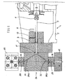
- Figure 1 is a side view and cross-section at mid length of the pump part of the homogeniser;
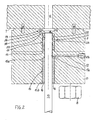
- Figure 2 is a side view and enlarged cross-section at mid length of the guide chamber for the single-acting reciprocating plunger;
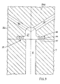
- Figure 3 is a side view and enlarged cross-section at mid length of the manifold connecting the compression chamber and the valves;
- Figure 4 is a side view and enlarged cross-section at mid length of a non-return delivery valve.
- With reference to the accompanying drawings, the numeral 1 denotes as a whole a homogeniser whose body 2 houses a cross-head guide piston 3, driven in a substantially known way, to the end of which a
clamp 4 fixes areciprocating plunger 5 in a compression chamber or cylinder 6. - The
plunger 5 is preferably made of a ceramic material such as pure silicon nitride Si3N4. - The compression chamber 6 is formed inside a
first block 7 to which stud bolts 8 fix ahousing flange 9 and alocking flange 10, the latter both preferably cylindrical and between them forming a guide chamber 11 for theplunger 5 coaxial with the compression chamber 6 (Figure 2). - To prevent problems with the coaxial alignment between the compression chamber 6 and the guide chamber 11 for the
plunger 5, and at the same time to facilitate assembly in sequence on theblock 7 first of thehousing flange 9 then thelocking flange 10, theblock 7 and thehousing flange 9 have, on their surfaces which face one another, a plurality of cylindrical connecting and centring pins 12, whilst thelocking flange 10 has, on the surface facing the housing flange 9 aprojection 13 having the shape of a truncated cylinder designed to fit into a recess in the surface of thehousing flange 9. - Inside the
locking flange 10 there is aseat 14, formed by a widening of the cross-section of the guide chamber 11 hole, for housing a guide bushing 15 for theplunger 5, made of self-lubricating plastic material, preferably PEEK, and having oneend 15a in contact with the widening of the cross-section of the guide chamber 11 hole and theopposite end 15b clamped by anelastic stop ring 16. Saidguide bushing 15 is preferably characterised by two or more longitudinal cuts designed to reduce the contact surface between thebushing 15 and theplunger 5 to limit friction and allow evacuation of the lubricating liquid used from a lubricatingliquid feed pipe 17, present on thelocking flange 10 and preferably angled so that it is perpendicular to a horizontal plane passing through the axis of the guide chamber 11 and parallel with the surface of thelocking flange 10 in contact with thehousing flange 9. - Said lubricating
pipe 17, supplied with water or another type of liquid or emulsion, has one end 17a opening into theplunger 5 guide chamber 11 and theopposite end 17b terminating on the side wall of thelocking flange 10. - Inside the
housing flange 9, along the hole forming the guide chamber 11, there is a first widening of thecross-section 18 and a second widening of thecross-section 19, separated from one another by ashoulder 20. - The first widening of the
cross-section 18 involves the insertion of a first dynamic seal unit 21 acting on the surface of thereciprocating plunger 5, having a first self-energisingseal 22, preferably shaped so that it has a single sealing lip and preferably made of a combination of plastic materials such as high molecular weight PE and - PEEK, and fitted with an energising ring made of an elastomer.
- The first self-energising seal and a bearing assembly 23 face one another and are respectively closed upstream of the first self-energising
seal 22 by theshoulder 20 and downstream of the bearing assembly 23 by theprojection 13 on thelocking flange 10. Theprojection 13 is used to centre the PEEK bushing 15 relative to thehousing flange 9. - The bearing assembly 23 is made of special non-galling stainless steel, preferably Nitronic 60, and is coaxial with and alongside the first self-energising
seal 22 and equipped with a system for extraction from its housing such as a suitably sized thread. - The second widening of the
cross-section 19 houses a second static seal unit 24 having a second self-energising seal 25 (with dimensions and geometry allowing containment of the very high pressures and preferably made of polyurethane with Shore hardness 90-98), blocked upstream of it by the surface of theblock 7 and downstream of it by theshoulder 20. The seal 25 does not make contact with theplunger 5 and is designed to contain the pressurised fluid between theblock 7 and the chamber 6; it may also be fitted with an external anti-extrusion ring 39. - The
numeral 26 denotes a block consisting of two half-parts orplates 26a and 26b rigidly clamped to one another by fixing means, preferably stud bolts not illustrated in Figure 1. - The insides of the two
plates 26a and 26b have been machined to make grooves in them designed to house aninternal manifold 27, preferably having a hemispherical shape, connecting the compression chamber 6 and a non-return intake valve 28 and anon-return delivery valve 29 housed incontainers 30 inserted between thecentral blocks 26 and respectively the delivery manifold 40 and thelower support flanges 41. - The
block 26 may also consist of a single piece, directly worked with a machine tool to create thechannels manifold hole 27 opposite the rear surface of theblock 26. - The non-return intake valve 28 is connected to the
internal manifold 27 by thechannel 31 which forms an intake pipe and thenon-return delivery valve 29 is connected to theinternal manifold 27 by thechannel 32 which forms a delivery pipe. - The intake pipe and delivery pipe are arranged in such a way that they are specular with one another relative to a horizontal plane passing through the axis of the pumping chamber 6 and set at an angle α to the normal to said horizontal plane which varies from 45 to 62 degrees, preferably 56 degrees.
- Advantageously, the internal surfaces of the
manifold 27 and of the intake anddelivery pipes - For each
non-return valve 28, 29, hollows are made close to the upper and lower surfaces of thevalve containers 30, respectively a first hollow 33 upstream of the non-return valve and a second hollow 34 downstream of it (Figure 4). - Said
hollows static seal unit 35 having ananti-extrusion ring 36, preferably a circular ring with a rectangular cross-section, inside which a third self-energisingseal 37 is fitted. - Said third
static seal unit 35 is also inserted, by means of a third hollow 38, close to theinternal manifold 27, more precisely at the intersection between the manifold and the compression chamber 6 (Figure 3). - The third
static seal unit 35 has one end closed by theblock 7 and the opposite end contained in a widening of the cross-section of theinternal manifold 27. - Each
anti-extrusion ring 36 is shaped in such a way as to create an interference fit with the height of the respective hollow 33, 34, 38, preferably by 0.1 mm, so that, during assembly, the ring forms a mechanical seal on the hollow and at the same time guarantees correct self-energisingseal 37 preloading. - The
numeral 40 denotes a delivery manifold connecting the two ormore delivery valve 29 units, whilst 41 denotes a support flange for the intake valve 28 unit for each plunger connected to the pump intake manifold.
Claims (18)
- A homogeniser (1) for continuous treatment of fluids at very high pressure, of the type comprising:- at least one single-acting plunger (5) with reciprocating motion from a guide chamber (11) to a compression chamber (6) from a fluid intake position to a fluid delivery position;- a block (26) for each plunger, connecting the compression chamber (6) with at least one intake valve (28) and with at least one delivery valve (29) for each plunger;- an internal manifold (27) connecting the compression chamber (6) with the intake valves (28) and delivery valves (29);- at least one intake pipe (31) and at least one delivery pipe (32) both communicating with the manifold (27) and respectively terminating in the intake valve (28) and in the delivery valve (29),characterised in that the intake valve (28) and the delivery valve (29) are housed in separated containers (30) fixed to the block (26) and the homogeniser (1) comprises at least one of the following units:- a first, dynamic seal unit (21) positioned around the guide chamber (11) and in contact with the surface of the reciprocating plunger (5), designed to create a seal on the plunger (5) during compression;- a second, static seal unit (24) located close to the intersection between the compression chamber (6) and the guide chamber (11), being designed to contain the pressure generated in the pump during compression between the opposite surfaces of a block (7) and a housing flange (9) for a dynamic seal (21) ;- a third, static seal unit (35) located upstream and downstream of each valve (28, 29) and at the intersection between the manifold (27) and the compression chamber (6), respectively housed in hollows (33, 34, 38) designed to prevent fluid from escaping.
- The homogeniser according to claim 1, characterised in that the first, dynamic seal unit (21) comprises:- at least one first self-energising seal (22) with an energising ring made of an elastomer;- at least one bearing assembly (23), coaxial with and alongside the first self-energising seal (22) and equipped with a system for extraction from its housing such as a suitably sized thread.
- The homogeniser according to claim 2, wherein the first self-energising seal (22) has a single sealing lip and is made with a combination of plastic materials, high molecular weight PE and PEEK.
- The homogeniser according to claim 2, wherein the bearing assembly (23) is made of special non-galling stainless steel, such as Nitronic 60.
- The homogeniser according to claim 1, wherein the second seal unit (24) has a second self-energising static seal (25) with dimensions and geometry which allow the containment of very high pressures, and if necessary fitted with an external anti-extrusion ring (39).
- The homogeniser according to claim 1, wherein the third seal unit comprises:- at least one anti-extrusion ring (36) with a rectangular cross-section and a circular ring cross-section in the direction orthogonal to the axis of symmetry;- at least a third self-energising seal (37) inside the respective anti-extrusion ring (36).
- The homogeniser according to claim 6, wherein each anti-extrusion ring (36) is mounted in such a way as to create an interference fit with the height of the hollow (33, 34, 38) for a more effective mechanical seal.
- The homogeniser according to claim 7, wherein the interference fit of each anti-extrusion ring (36) is equal to 0.1 mm on the height of the hollow (33, 34, 38) in which the ring is housed.
- The homogeniser according to claim 1, wherein the internal surfaces of the manifold (27), the intake pipe (31) and the delivery pipe (32), exposed to the pressure of the fluid, are treated by manual polishing, radiusing of any edges at the intersections of concurrent holes, micro shot peening and electropolishing.
- The homogeniser according to claim 1, wherein the plunger (5) is made of a ceramic material such as pure silicon nitride Si3N4.
- The homogeniser according to claim 1, wherein a plunger seal apparatus is present, housed in the guide chamber (11) and locked by a locking flange (10) outside the compression chamber contained in the block (7).
- The homogeniser according to claim 1, wherein a lubricating - coolant fluid feed channel (17) is positioned on a locking flange (10) immediately axially close to a first, dynamic seal unit (21).
- The homogeniser according to claim 1, wherein the plunger comprises a guide consisting of a bushing (15) housed in a locking flange (10) and centred relative to a housing flange (9) by a concentric centring projection (13).
- The homogeniser according to claim 13, wherein the housing flange (9) is centred relative to the block (7) by cylindrical pins (12).
- The homogeniser according to claim 1, wherein a delivery manifold (40) connects the delivery valve units (29).
- The homogeniser according to claim 1, wherein a support flange (41) for the intake valve (28) unit for each plunger is connected to the low pressure intake manifold of the pump.
- The homogeniser according to claim 1, wherein each static seal unit (35) consisting of a self-energising seal (37) and an anti-extrusion ring (36) can be applied to all of the high pressure seal zones including the connection between the delivery manifold and a homogenising valve.
- The homogeniser according to any of the foregoing claims, characterised in that it is equipped with an adjustable homogenising valve installed at the outlet of a delivery manifold (40).
Applications Claiming Priority (2)
| Application Number | Priority Date | Filing Date | Title |
|---|---|---|---|
| IT000031A ITPR20040031A1 (en) | 2004-04-09 | 2004-04-09 | HOMOGENIZER FOR THE CONTINUOUS TREATMENT OF HIGH PRESSURE FLUIDS. |
| PCT/IB2004/051643 WO2005097308A1 (en) | 2004-04-09 | 2004-09-01 | A homogeniser for the continuous treatment of fluids at very high pressure. |
Publications (2)
| Publication Number | Publication Date |
|---|---|
| EP1740293A1 EP1740293A1 (en) | 2007-01-10 |
| EP1740293B1 true EP1740293B1 (en) | 2007-08-08 |
Family
ID=34958453
Family Applications (1)
| Application Number | Title | Priority Date | Filing Date |
|---|---|---|---|
| EP04769899A Expired - Lifetime EP1740293B1 (en) | 2004-04-09 | 2004-09-01 | A homogeniser for the continuous treatment of fluids at very high pressure |
Country Status (12)
| Country | Link |
|---|---|
| US (1) | US7661873B2 (en) |
| EP (1) | EP1740293B1 (en) |
| JP (1) | JP4605722B2 (en) |
| CN (1) | CN100556520C (en) |
| AT (1) | ATE369204T1 (en) |
| CA (1) | CA2561843C (en) |
| DE (1) | DE602004008120T2 (en) |
| DK (1) | DK1740293T3 (en) |
| ES (1) | ES2291938T3 (en) |
| IL (1) | IL178385A0 (en) |
| IT (1) | ITPR20040031A1 (en) |
| WO (1) | WO2005097308A1 (en) |
Cited By (1)
| Publication number | Priority date | Publication date | Assignee | Title |
|---|---|---|---|---|
| WO2013140281A1 (en) | 2012-03-19 | 2013-09-26 | Gea Mechanical Equipment Italia S.P.A. | Apparatus for thermal treatment of water with regeneration for flushing aseptic chambers of high-pressure homogenisers or pumps |
Families Citing this family (7)
| Publication number | Priority date | Publication date | Assignee | Title |
|---|---|---|---|---|
| FR2945458B1 (en) | 2009-05-13 | 2011-06-17 | Sanofi Aventis | HIGH PRESSURE HOMOGENIZATION WITH A SILICON NITRIDE VALVE |
| ITPR20100072A1 (en) * | 2010-09-30 | 2012-03-31 | Bertoli S R L | COMPRESSION HEAD FOR THE TREATMENT OF PRODUCTS BY HOMOGENIZATION |
| DE102014104050A1 (en) * | 2014-03-24 | 2015-09-24 | Netzsch-Feinmahltechnik Gmbh | Homogenizer with a high pressure and a low pressure chamber |
| IT201600117208A1 (en) * | 2016-11-21 | 2018-05-21 | Interpump Group S P A | Pumping group |
| DE102019201847A1 (en) * | 2019-02-13 | 2020-08-13 | Hst Maschinenbau Gmbh | High pressure pump, pump piston and process for homogenizing |
| EP4724190A1 (en) * | 2023-06-07 | 2026-04-15 | Idex Mpt Inc. | Homogenizer with fixed geometry microfluidic chambers with a high pressure multiplex pumping system |
| EP4724704A1 (en) * | 2023-06-09 | 2026-04-15 | Idex Mpt Inc. | A sanitary homogenizer with cleanable and drainable components |
Family Cites Families (7)
| Publication number | Priority date | Publication date | Assignee | Title |
|---|---|---|---|---|
| GB1292641A (en) * | 1969-03-17 | 1972-10-11 | Atomic Energy Authority Uk | Improvements in pressure vessel assemblies |
| FR2399593A1 (en) * | 1977-08-01 | 1979-03-02 | Bertin & Cie | SEALING DEVICE FOR HYDRAULIC PISTON MECHANISM |
| SE501310C2 (en) * | 1993-06-11 | 1995-01-16 | Asea Brown Boveri | Device for high pressure treatment of substances |
| US6162031A (en) * | 1998-10-30 | 2000-12-19 | Flow International Corporation | Seal seat for high pressure pumps and vessels |
| US6305265B1 (en) * | 1999-06-03 | 2001-10-23 | Bechtel Bwxt Idaho Llc | Method and apparatus for pressurizing vaporous fluids |
| JP2001295728A (en) * | 2000-04-18 | 2001-10-26 | Toyota Motor Corp | High pressure pump |
| JP4296060B2 (en) * | 2003-08-25 | 2009-07-15 | ヤンマー株式会社 | Reactors for organic substances using supercritical fluids or subcritical fluids |
-
2004
- 2004-04-09 IT IT000031A patent/ITPR20040031A1/en unknown
- 2004-09-01 CA CA002561843A patent/CA2561843C/en not_active Expired - Lifetime
- 2004-09-01 CN CNB200480042711XA patent/CN100556520C/en not_active Expired - Lifetime
- 2004-09-01 WO PCT/IB2004/051643 patent/WO2005097308A1/en not_active Ceased
- 2004-09-01 JP JP2007506846A patent/JP4605722B2/en not_active Expired - Lifetime
- 2004-09-01 EP EP04769899A patent/EP1740293B1/en not_active Expired - Lifetime
- 2004-09-01 US US10/594,362 patent/US7661873B2/en not_active Expired - Lifetime
- 2004-09-01 DK DK04769899T patent/DK1740293T3/en active
- 2004-09-01 DE DE602004008120T patent/DE602004008120T2/en not_active Expired - Lifetime
- 2004-09-01 ES ES04769899T patent/ES2291938T3/en not_active Expired - Lifetime
- 2004-09-01 AT AT04769899T patent/ATE369204T1/en not_active IP Right Cessation
-
2006
- 2006-09-28 IL IL178385A patent/IL178385A0/en unknown
Cited By (1)
| Publication number | Priority date | Publication date | Assignee | Title |
|---|---|---|---|---|
| WO2013140281A1 (en) | 2012-03-19 | 2013-09-26 | Gea Mechanical Equipment Italia S.P.A. | Apparatus for thermal treatment of water with regeneration for flushing aseptic chambers of high-pressure homogenisers or pumps |
Also Published As
| Publication number | Publication date |
|---|---|
| CN100556520C (en) | 2009-11-04 |
| ITPR20040031A1 (en) | 2004-07-09 |
| EP1740293A1 (en) | 2007-01-10 |
| WO2005097308A1 (en) | 2005-10-20 |
| DE602004008120T2 (en) | 2008-04-24 |
| CN1938075A (en) | 2007-03-28 |
| JP4605722B2 (en) | 2011-01-05 |
| IL178385A0 (en) | 2007-02-11 |
| US7661873B2 (en) | 2010-02-16 |
| CA2561843A1 (en) | 2005-10-20 |
| ATE369204T1 (en) | 2007-08-15 |
| US20080232189A1 (en) | 2008-09-25 |
| JP2007532292A (en) | 2007-11-15 |
| ES2291938T3 (en) | 2008-03-01 |
| CA2561843C (en) | 2009-10-27 |
| DE602004008120D1 (en) | 2007-09-20 |
| DK1740293T3 (en) | 2007-11-19 |
Similar Documents
| Publication | Publication Date | Title |
|---|---|---|
| US11181108B2 (en) | Plunger pump fluid end | |
| CA2561843C (en) | A homogeniser for the continuous treatment of fluids at very high pressure | |
| US9188122B1 (en) | Valve and seat assembly for high pressure pumps and method of use | |
| US20180298894A1 (en) | Valve seat for reciprocating pump | |
| EP2708886B1 (en) | Fluidic interface valve assembly with elastomeric ferrule device | |
| KR100771456B1 (en) | Fluid-Directed Multiport Rotary Valves | |
| US20120247296A1 (en) | Waterjet cutting system fluid conduits and associated methods | |
| US7540230B2 (en) | Three-way poppet valve for work exchanger | |
| ES2913793T3 (en) | Compact ultra high pressure valve with regulation capacity | |
| EP2085613A2 (en) | High pressure valve assembly | |
| IL197798A (en) | Rotary pressure transfer device and method of operation thereof | |
| US5226799A (en) | Ultrahigh pressure poppet valve with low wear | |
| US5273407A (en) | Homogenizing system having improved fluid flow path | |
| EP3277953B1 (en) | System for high pressure, high shear processing of fluids | |
| US20150272605A1 (en) | Sterilizable Pump Unit | |
| EP0786595A2 (en) | Method and apparatus for pressure processing a pumpable substance | |
| US20090146095A1 (en) | Drainable radial diaphragm valve | |
| US8585277B2 (en) | Homogenizing valve | |
| US12044233B2 (en) | Axial piston pump with inclined plate | |
| CN112747143B (en) | Automatic two-way valve and pump equipped with the valve | |
| EP4215748B1 (en) | Axial piston pump with inclined plate | |
| US12605681B2 (en) | Cartridge and a homogenizing valve comprising said cartridge | |
| RU2702830C1 (en) | Pump | |
| CN120476256A (en) | Piston pump of the type having at least three pumping chambers | |
| RU2250391C2 (en) | Plunger pump check valve |
Legal Events
| Date | Code | Title | Description |
|---|---|---|---|
| PUAI | Public reference made under article 153(3) epc to a published international application that has entered the european phase |
Free format text: ORIGINAL CODE: 0009012 |
|
| 17P | Request for examination filed |
Effective date: 20061109 |
|
| AK | Designated contracting states |
Kind code of ref document: A1 Designated state(s): AT BE BG CH CY CZ DE DK EE ES FI FR GB GR HU IE IT LI LU MC NL PL PT RO SE SI SK TR |
|
| GRAP | Despatch of communication of intention to grant a patent |
Free format text: ORIGINAL CODE: EPIDOSNIGR1 |
|
| DAX | Request for extension of the european patent (deleted) | ||
| GRAS | Grant fee paid |
Free format text: ORIGINAL CODE: EPIDOSNIGR3 |
|
| GRAA | (expected) grant |
Free format text: ORIGINAL CODE: 0009210 |
|
| AK | Designated contracting states |
Kind code of ref document: B1 Designated state(s): AT BE BG CH CY CZ DE DK EE ES FI FR GB GR HU IE IT LI LU MC NL PL PT RO SE SI SK TR |
|
| REG | Reference to a national code |
Ref country code: GB Ref legal event code: FG4D |
|
| REG | Reference to a national code |
Ref country code: CH Ref legal event code: EP |
|
| REG | Reference to a national code |
Ref country code: IE Ref legal event code: FG4D |
|
| REF | Corresponds to: |
Ref document number: 602004008120 Country of ref document: DE Date of ref document: 20070920 Kind code of ref document: P |
|
| REG | Reference to a national code |
Ref country code: CH Ref legal event code: NV Representative=s name: BUGNION S.A. |
|
| REG | Reference to a national code |
Ref country code: SE Ref legal event code: TRGR |
|
| REG | Reference to a national code |
Ref country code: DK Ref legal event code: T3 |
|
| ET | Fr: translation filed | ||
| PG25 | Lapsed in a contracting state [announced via postgrant information from national office to epo] |
Ref country code: FI Free format text: LAPSE BECAUSE OF FAILURE TO SUBMIT A TRANSLATION OF THE DESCRIPTION OR TO PAY THE FEE WITHIN THE PRESCRIBED TIME-LIMIT Effective date: 20070808 |
|
| PG25 | Lapsed in a contracting state [announced via postgrant information from national office to epo] |
Ref country code: AT Free format text: LAPSE BECAUSE OF FAILURE TO SUBMIT A TRANSLATION OF THE DESCRIPTION OR TO PAY THE FEE WITHIN THE PRESCRIBED TIME-LIMIT Effective date: 20070808 Ref country code: PL Free format text: LAPSE BECAUSE OF FAILURE TO SUBMIT A TRANSLATION OF THE DESCRIPTION OR TO PAY THE FEE WITHIN THE PRESCRIBED TIME-LIMIT Effective date: 20070808 |
|
| REG | Reference to a national code |
Ref country code: ES Ref legal event code: FG2A Ref document number: 2291938 Country of ref document: ES Kind code of ref document: T3 |
|
| PG25 | Lapsed in a contracting state [announced via postgrant information from national office to epo] |
Ref country code: BE Free format text: LAPSE BECAUSE OF FAILURE TO SUBMIT A TRANSLATION OF THE DESCRIPTION OR TO PAY THE FEE WITHIN THE PRESCRIBED TIME-LIMIT Effective date: 20070808 |
|
| PG25 | Lapsed in a contracting state [announced via postgrant information from national office to epo] |
Ref country code: MC Free format text: LAPSE BECAUSE OF NON-PAYMENT OF DUE FEES Effective date: 20070930 Ref country code: GR Free format text: LAPSE BECAUSE OF FAILURE TO SUBMIT A TRANSLATION OF THE DESCRIPTION OR TO PAY THE FEE WITHIN THE PRESCRIBED TIME-LIMIT Effective date: 20071109 |
|
| PG25 | Lapsed in a contracting state [announced via postgrant information from national office to epo] |
Ref country code: SK Free format text: LAPSE BECAUSE OF FAILURE TO SUBMIT A TRANSLATION OF THE DESCRIPTION OR TO PAY THE FEE WITHIN THE PRESCRIBED TIME-LIMIT Effective date: 20070808 Ref country code: CZ Free format text: LAPSE BECAUSE OF FAILURE TO SUBMIT A TRANSLATION OF THE DESCRIPTION OR TO PAY THE FEE WITHIN THE PRESCRIBED TIME-LIMIT Effective date: 20070808 Ref country code: PT Free format text: LAPSE BECAUSE OF FAILURE TO SUBMIT A TRANSLATION OF THE DESCRIPTION OR TO PAY THE FEE WITHIN THE PRESCRIBED TIME-LIMIT Effective date: 20080108 |
|
| PLBE | No opposition filed within time limit |
Free format text: ORIGINAL CODE: 0009261 |
|
| STAA | Information on the status of an ep patent application or granted ep patent |
Free format text: STATUS: NO OPPOSITION FILED WITHIN TIME LIMIT |
|
| PG25 | Lapsed in a contracting state [announced via postgrant information from national office to epo] |
Ref country code: RO Free format text: LAPSE BECAUSE OF FAILURE TO SUBMIT A TRANSLATION OF THE DESCRIPTION OR TO PAY THE FEE WITHIN THE PRESCRIBED TIME-LIMIT Effective date: 20070808 |
|
| 26N | No opposition filed |
Effective date: 20080509 |
|
| PG25 | Lapsed in a contracting state [announced via postgrant information from national office to epo] |
Ref country code: EE Free format text: LAPSE BECAUSE OF FAILURE TO SUBMIT A TRANSLATION OF THE DESCRIPTION OR TO PAY THE FEE WITHIN THE PRESCRIBED TIME-LIMIT Effective date: 20070808 |
|
| PG25 | Lapsed in a contracting state [announced via postgrant information from national office to epo] |
Ref country code: SI Free format text: LAPSE BECAUSE OF FAILURE TO SUBMIT A TRANSLATION OF THE DESCRIPTION OR TO PAY THE FEE WITHIN THE PRESCRIBED TIME-LIMIT Effective date: 20070808 |
|
| PG25 | Lapsed in a contracting state [announced via postgrant information from national office to epo] |
Ref country code: CY Free format text: LAPSE BECAUSE OF FAILURE TO SUBMIT A TRANSLATION OF THE DESCRIPTION OR TO PAY THE FEE WITHIN THE PRESCRIBED TIME-LIMIT Effective date: 20070808 |
|
| PG25 | Lapsed in a contracting state [announced via postgrant information from national office to epo] |
Ref country code: LU Free format text: LAPSE BECAUSE OF NON-PAYMENT OF DUE FEES Effective date: 20070901 Ref country code: BG Free format text: LAPSE BECAUSE OF FAILURE TO SUBMIT A TRANSLATION OF THE DESCRIPTION OR TO PAY THE FEE WITHIN THE PRESCRIBED TIME-LIMIT Effective date: 20071108 |
|
| PG25 | Lapsed in a contracting state [announced via postgrant information from national office to epo] |
Ref country code: HU Free format text: LAPSE BECAUSE OF FAILURE TO SUBMIT A TRANSLATION OF THE DESCRIPTION OR TO PAY THE FEE WITHIN THE PRESCRIBED TIME-LIMIT Effective date: 20080209 Ref country code: TR Free format text: LAPSE BECAUSE OF FAILURE TO SUBMIT A TRANSLATION OF THE DESCRIPTION OR TO PAY THE FEE WITHIN THE PRESCRIBED TIME-LIMIT Effective date: 20070808 |
|
| PGFP | Annual fee paid to national office [announced via postgrant information from national office to epo] |
Ref country code: IE Payment date: 20100830 Year of fee payment: 7 |
|
| REG | Reference to a national code |
Ref country code: NL Ref legal event code: TD Effective date: 20120208 Ref country code: NL Ref legal event code: SD Effective date: 20120208 Ref country code: CH Ref legal event code: PFA Owner name: GEA MECHANICAL EQUIPMENT ITALIA S.P.A. Free format text: NIRO-SOAVI S.P.A.#VIA MARIO DA ERBA EDOARI, 29#43100 PARMA (IT) -TRANSFER TO- GEA MECHANICAL EQUIPMENT ITALIA S.P.A.#VIA ANGELO MARIA DA ERBA EDOARI 29#43123 PARMA (IT) |
|
| REG | Reference to a national code |
Ref country code: FR Ref legal event code: CD Owner name: GEA MECHANICAL EQUIPMENT ITALIA S.P.A. Effective date: 20120224 Ref country code: FR Ref legal event code: CA Effective date: 20120224 |
|
| REG | Reference to a national code |
Ref country code: IE Ref legal event code: MM4A |
|
| REG | Reference to a national code |
Ref country code: DE Ref legal event code: R081 Ref document number: 602004008120 Country of ref document: DE Owner name: GEA MECHANICAL EQUIPMENT ITALIA S.P.A., IT Free format text: FORMER OWNER: NIRO SOAVI S.P.A., PARMA, IT Effective date: 20120503 Ref country code: DE Ref legal event code: R082 Ref document number: 602004008120 Country of ref document: DE Representative=s name: MITSCHERLICH, PATENT- UND RECHTSANWAELTE PARTM, DE Effective date: 20120503 |
|
| PG25 | Lapsed in a contracting state [announced via postgrant information from national office to epo] |
Ref country code: IE Free format text: LAPSE BECAUSE OF NON-PAYMENT OF DUE FEES Effective date: 20110901 |
|
| REG | Reference to a national code |
Ref country code: ES Ref legal event code: PC2A Owner name: GEA MECHANICAL EQUIPMENT ITALIA S.P.A. Effective date: 20120904 |
|
| REG | Reference to a national code |
Ref country code: FR Ref legal event code: PLFP Year of fee payment: 12 |
|
| REG | Reference to a national code |
Ref country code: FR Ref legal event code: PLFP Year of fee payment: 13 |
|
| REG | Reference to a national code |
Ref country code: FR Ref legal event code: PLFP Year of fee payment: 14 |
|
| REG | Reference to a national code |
Ref country code: FR Ref legal event code: PLFP Year of fee payment: 15 |
|
| REG | Reference to a national code |
Ref country code: DE Ref legal event code: R079 Ref document number: 602004008120 Country of ref document: DE Free format text: PREVIOUS MAIN CLASS: B01F0005000000 Ipc: B01F0025000000 |
|
| P01 | Opt-out of the competence of the unified patent court (upc) registered |
Effective date: 20230526 |
|
| PGFP | Annual fee paid to national office [announced via postgrant information from national office to epo] |
Ref country code: NL Payment date: 20230926 Year of fee payment: 20 Ref country code: GB Payment date: 20230926 Year of fee payment: 20 |
|
| PGFP | Annual fee paid to national office [announced via postgrant information from national office to epo] |
Ref country code: SE Payment date: 20230926 Year of fee payment: 20 Ref country code: FR Payment date: 20230926 Year of fee payment: 20 Ref country code: DK Payment date: 20230927 Year of fee payment: 20 Ref country code: DE Payment date: 20230928 Year of fee payment: 20 |
|
| PGFP | Annual fee paid to national office [announced via postgrant information from national office to epo] |
Ref country code: ES Payment date: 20231017 Year of fee payment: 20 |
|
| PGFP | Annual fee paid to national office [announced via postgrant information from national office to epo] |
Ref country code: IT Payment date: 20230925 Year of fee payment: 20 Ref country code: CH Payment date: 20231002 Year of fee payment: 20 |
|
| REG | Reference to a national code |
Ref country code: DE Ref legal event code: R071 Ref document number: 602004008120 Country of ref document: DE |
|
| REG | Reference to a national code |
Ref country code: DK Ref legal event code: EUP Expiry date: 20240901 |
|
| REG | Reference to a national code |
Ref country code: NL Ref legal event code: MK Effective date: 20240831 |
|
| REG | Reference to a national code |
Ref country code: CH Ref legal event code: PL |
|
| REG | Reference to a national code |
Ref country code: GB Ref legal event code: PE20 Expiry date: 20240831 |
|
| REG | Reference to a national code |
Ref country code: ES Ref legal event code: FD2A Effective date: 20240927 |
|
| PG25 | Lapsed in a contracting state [announced via postgrant information from national office to epo] |
Ref country code: GB Free format text: LAPSE BECAUSE OF EXPIRATION OF PROTECTION Effective date: 20240831 |
|
| PG25 | Lapsed in a contracting state [announced via postgrant information from national office to epo] |
Ref country code: ES Free format text: LAPSE BECAUSE OF EXPIRATION OF PROTECTION Effective date: 20240902 |
|
| REG | Reference to a national code |
Ref country code: SE Ref legal event code: EUG |
|
| PG25 | Lapsed in a contracting state [announced via postgrant information from national office to epo] |
Ref country code: GB Free format text: LAPSE BECAUSE OF EXPIRATION OF PROTECTION Effective date: 20240831 Ref country code: ES Free format text: LAPSE BECAUSE OF EXPIRATION OF PROTECTION Effective date: 20240902 |