EP1739791A1 - Crimp contact and gas sensor - Google Patents
Crimp contact and gas sensor Download PDFInfo
- Publication number
- EP1739791A1 EP1739791A1 EP06013129A EP06013129A EP1739791A1 EP 1739791 A1 EP1739791 A1 EP 1739791A1 EP 06013129 A EP06013129 A EP 06013129A EP 06013129 A EP06013129 A EP 06013129A EP 1739791 A1 EP1739791 A1 EP 1739791A1
- Authority
- EP
- European Patent Office
- Prior art keywords
- side walls
- bottom wall
- wire
- core wires
- wire hold
- Prior art date
- Legal status (The legal status is an assumption and is not a legal conclusion. Google has not performed a legal analysis and makes no representation as to the accuracy of the status listed.)
- Withdrawn
Links
- 230000004308 accommodation Effects 0.000 claims abstract description 18
- 230000001681 protective effect Effects 0.000 claims description 14
- 230000000630 rising effect Effects 0.000 claims description 9
- 239000007789 gas Substances 0.000 description 26
- 238000002788 crimping Methods 0.000 description 19
- 238000000034 method Methods 0.000 description 19
- 238000001816 cooling Methods 0.000 description 13
- 238000010438 heat treatment Methods 0.000 description 13
- 238000012360 testing method Methods 0.000 description 12
- 238000005259 measurement Methods 0.000 description 9
- 239000000314 lubricant Substances 0.000 description 7
- 239000000919 ceramic Substances 0.000 description 6
- 239000000463 material Substances 0.000 description 6
- 229910052751 metal Inorganic materials 0.000 description 6
- 239000002184 metal Substances 0.000 description 6
- 238000004364 calculation method Methods 0.000 description 4
- 238000011156 evaluation Methods 0.000 description 4
- 229910001026 inconel Inorganic materials 0.000 description 4
- WABPQHHGFIMREM-UHFFFAOYSA-N lead(0) Chemical compound [Pb] WABPQHHGFIMREM-UHFFFAOYSA-N 0.000 description 4
- RYGMFSIKBFXOCR-UHFFFAOYSA-N Copper Chemical compound [Cu] RYGMFSIKBFXOCR-UHFFFAOYSA-N 0.000 description 3
- 230000000052 comparative effect Effects 0.000 description 3
- 229910052802 copper Inorganic materials 0.000 description 3
- 239000010949 copper Substances 0.000 description 3
- 238000012856 packing Methods 0.000 description 2
- 229920001343 polytetrafluoroethylene Polymers 0.000 description 2
- 239000004810 polytetrafluoroethylene Substances 0.000 description 2
- 238000007789 sealing Methods 0.000 description 2
- 229910000881 Cu alloy Inorganic materials 0.000 description 1
- 229910000640 Fe alloy Inorganic materials 0.000 description 1
- 229910000691 Re alloy Inorganic materials 0.000 description 1
- 229910052581 Si3N4 Inorganic materials 0.000 description 1
- 229910001128 Sn alloy Inorganic materials 0.000 description 1
- 229910001069 Ti alloy Inorganic materials 0.000 description 1
- VRUVRQYVUDCDMT-UHFFFAOYSA-N [Sn].[Ni].[Cu] Chemical compound [Sn].[Ni].[Cu] VRUVRQYVUDCDMT-UHFFFAOYSA-N 0.000 description 1
- 229910045601 alloy Inorganic materials 0.000 description 1
- 239000000956 alloy Substances 0.000 description 1
- QVGXLLKOCUKJST-UHFFFAOYSA-N atomic oxygen Chemical compound [O] QVGXLLKOCUKJST-UHFFFAOYSA-N 0.000 description 1
- DMFGNRRURHSENX-UHFFFAOYSA-N beryllium copper Chemical compound [Be].[Cu] DMFGNRRURHSENX-UHFFFAOYSA-N 0.000 description 1
- BIJOYKCOMBZXAE-UHFFFAOYSA-N chromium iron nickel Chemical compound [Cr].[Fe].[Ni] BIJOYKCOMBZXAE-UHFFFAOYSA-N 0.000 description 1
- 238000004891 communication Methods 0.000 description 1
- IUYOGGFTLHZHEG-UHFFFAOYSA-N copper titanium Chemical compound [Ti].[Cu] IUYOGGFTLHZHEG-UHFFFAOYSA-N 0.000 description 1
- 230000007423 decrease Effects 0.000 description 1
- 238000006073 displacement reaction Methods 0.000 description 1
- 230000000694 effects Effects 0.000 description 1
- 239000007769 metal material Substances 0.000 description 1
- 239000000203 mixture Substances 0.000 description 1
- 238000012986 modification Methods 0.000 description 1
- 230000004048 modification Effects 0.000 description 1
- 239000001301 oxygen Substances 0.000 description 1
- 229910052760 oxygen Inorganic materials 0.000 description 1
- -1 polytetrafluoroethylene Polymers 0.000 description 1
- 238000003825 pressing Methods 0.000 description 1
- 230000000717 retained effect Effects 0.000 description 1
- DECCZIUVGMLHKQ-UHFFFAOYSA-N rhenium tungsten Chemical compound [W].[Re] DECCZIUVGMLHKQ-UHFFFAOYSA-N 0.000 description 1
- HQVNEWCFYHHQES-UHFFFAOYSA-N silicon nitride Chemical compound N12[Si]34N5[Si]62N3[Si]51N64 HQVNEWCFYHHQES-UHFFFAOYSA-N 0.000 description 1
- 239000000454 talc Substances 0.000 description 1
- 229910052623 talc Inorganic materials 0.000 description 1
- WFKWXMTUELFFGS-UHFFFAOYSA-N tungsten Chemical compound [W] WFKWXMTUELFFGS-UHFFFAOYSA-N 0.000 description 1
- 229910052721 tungsten Inorganic materials 0.000 description 1
- 239000010937 tungsten Substances 0.000 description 1
- UONOETXJSWQNOL-UHFFFAOYSA-N tungsten carbide Chemical compound [W+]#[C-] UONOETXJSWQNOL-UHFFFAOYSA-N 0.000 description 1
Images


Classifications
-
- H—ELECTRICITY
- H01—ELECTRIC ELEMENTS
- H01R—ELECTRICALLY-CONDUCTIVE CONNECTIONS; STRUCTURAL ASSOCIATIONS OF A PLURALITY OF MUTUALLY-INSULATED ELECTRICAL CONNECTING ELEMENTS; COUPLING DEVICES; CURRENT COLLECTORS
- H01R43/00—Apparatus or processes specially adapted for manufacturing, assembling, maintaining, or repairing of line connectors or current collectors or for joining electric conductors
- H01R43/04—Apparatus or processes specially adapted for manufacturing, assembling, maintaining, or repairing of line connectors or current collectors or for joining electric conductors for forming connections by deformation, e.g. crimping tool
- H01R43/058—Crimping mandrels
-
- H—ELECTRICITY
- H01—ELECTRIC ELEMENTS
- H01R—ELECTRICALLY-CONDUCTIVE CONNECTIONS; STRUCTURAL ASSOCIATIONS OF A PLURALITY OF MUTUALLY-INSULATED ELECTRICAL CONNECTING ELEMENTS; COUPLING DEVICES; CURRENT COLLECTORS
- H01R4/00—Electrically-conductive connections between two or more conductive members in direct contact, i.e. touching one another; Means for effecting or maintaining such contact; Electrically-conductive connections having two or more spaced connecting locations for conductors and using contact members penetrating insulation
- H01R4/10—Electrically-conductive connections between two or more conductive members in direct contact, i.e. touching one another; Means for effecting or maintaining such contact; Electrically-conductive connections having two or more spaced connecting locations for conductors and using contact members penetrating insulation effected solely by twisting, wrapping, bending, crimping, or other permanent deformation
- H01R4/18—Electrically-conductive connections between two or more conductive members in direct contact, i.e. touching one another; Means for effecting or maintaining such contact; Electrically-conductive connections having two or more spaced connecting locations for conductors and using contact members penetrating insulation effected solely by twisting, wrapping, bending, crimping, or other permanent deformation by crimping
- H01R4/183—Electrically-conductive connections between two or more conductive members in direct contact, i.e. touching one another; Means for effecting or maintaining such contact; Electrically-conductive connections having two or more spaced connecting locations for conductors and using contact members penetrating insulation effected solely by twisting, wrapping, bending, crimping, or other permanent deformation by crimping for cylindrical elongated bodies, e.g. cables having circular cross-section
- H01R4/184—Electrically-conductive connections between two or more conductive members in direct contact, i.e. touching one another; Means for effecting or maintaining such contact; Electrically-conductive connections having two or more spaced connecting locations for conductors and using contact members penetrating insulation effected solely by twisting, wrapping, bending, crimping, or other permanent deformation by crimping for cylindrical elongated bodies, e.g. cables having circular cross-section comprising a U-shaped wire-receiving portion
Definitions
- the present invention relates to a crimp contact and a gas sensor.
- the term “front” refers to a sensing end side with respect to an axial direction of the gas sensor, and the term “rear” refers to a side opposite to the front side.
- Japanese Laid-Open Patent Publication No. 64-041184 discloses one conventional type of crimp contact that has wire hold portions extending axially and holding therein core wires of an electrical lead.
- the crimp contact is suitably used for e.g. a gas sensor in an automotive exhaust system to connect the electrical lead wire with a sensor element of the gas sensor for signal output from the sensor element to an external device.
- the wire hold portions of the crimp contact hold the lead core wires tightly so as to prevent or minimize a widening of clearance between the wire hold portions and the lead core wires and avoid an increase in electrical resistance between the crimp contact and the electrical lead during the heating and cooling cycles of operation of the gas sensor.
- the wire hold portions are simply crimped onto the lead core wires with no specific dimension control through the application of a lubricant and thus may not be able to hold the lead core wires sufficiently tightly. It is further difficult in the conventional crimp contact to bend the wire hold portions adequately during the crimping process depending on the crimping process conditions (where the use of the lubricant is impractical in view of the crimp contact quality) and the crimp contact material so that the wire hold portions cannot hold the lead core wires tightly. As a result, there often arises an increase in electrical resistance between the conventional crimp contact and the electrical lead during the heating and cooling cycles of operation. The gas sensor with such a conventional crimp contact fails to secure accurate signal output over a long period of time.
- a crimp contact comprising a wire hold portion extending in an axial direction thereof and holding therein core wires of an electrical lead, the wire hold portion having, when viewed in cross section perpendicular to the axial direction, a bottom wall and a pair of side walls rising from opposite sides of the bottom wall and bent in such a manner as to turn top ends of the respective side walls toward the bottom wall and bring the top ends of the side walls into contact with each other to define a wire accommodation space in which the lead core wires are enclosed by the bottom wall and the side walls, and the wire hold portion being configured to satisfy the following equations: ⁇ (W1 - W2)/2 ⁇ /W3 ⁇ 1.2; and H2/H1 ⁇ 0.5 where W1 is a maximum width of the wire hold portion; W2 is a maximum width of the wire accommodation space; W3 is a minimum thickness of the bottom wall; H1 is a maximum thickness of the wire hold portion; and H2 is a maximum distance from an outermost point
- a crimp contact comprising a wire hold portion extending in an axial direction thereof and holding therein core wires of an electrical lead, the wire hold portion having, when viewed in cross section perpendicular to the axial direction, a bottom wall and a pair of side walls rising from opposite sides of the bottom wall, with top ends of the respective side walls previously inclined toward each other, and bent in such a manner as to turn the previously inclined top ends of the side walls toward the bottom wall and bring one of the previously inclined top ends of the side walls into contact with the other of the previously top ends of the side walls to define a wire accommodation space in which the lead core wires are enclosed by the bottom wall and the side walls.
- a gas sensor comprising: a cylindrical metallic housing; a sensor element disposed in the housing with at least a sensor portion of the sensor element protruding from a front end of the housing; a protective cover attached to a rear end of the housing; an electrical lead extending within the protective cover to produce a signal output from the sensor element to an external device; and a crimp contact connecting the a front end of electrical lead to a terminal portion of the sensor element, the crimp contact having a wire hold portion extending in an axial direction thereof and holding therein core wires of the electrical lead, the wire hold portion having, when viewed in cross section perpendicular to the axial direction, a bottom wall and a pair of side walls rising from opposite sides of the bottom wall and bent in such a manner as to turn top ends of the respective side walls toward the bottom wall and bring the top ends of the side walls into contact with each other to define a wire accommodation space in which the lead core wires are enclosed by the bottom wall and the side walls
- a gas sensor comprising: a cylindrical metallic housing; a sensor element disposed in the housing with at least a sensor portion of the sensor element protruding from a front end of the housing; a protective cover attached to a rear end of the housing; an electrical lead extending within the protective cover to produce a signal output from the sensor element to an external device; and a crimp contact connecting a front end of the electrical lead to a terminal portion of the sensor element, the crimp contact having a wire hold portion extending in an axial direction thereof and holding therein core wires of the electrical lead, and the wire hold portion having, when viewed in cross section perpendicular to the axial direction, a bottom wall and a pair of side walls rising from opposite sides of the bottom wall, with top ends of the respective side walls previously inclined toward each other, and bent in such a manner as to turn the previously inclined top ends of the side walls toward the bottom wall and bring one of the previously inclined top ends of the side walls into contact with the other of the
- FIG. 1 is a sectional view of a gas sensor according to one exemplary embodiment of the present invention.
- FIG. 2 is a perspective view of a crimp contact formed with wire hold portions, before being crimped onto the core wires of an electrical lead, according to a first or second embodiment of the present invention.
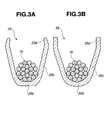
- FIG. 3A is a sectional view of the wire hold portion of the crimp contact, before being crimped onto the lead core wires, according to the first embodiment of the present invention.
- FIG. 3B is a sectional view of the wire hold portion of the crimp contact, before being crimped onto the lead core wires, according to the second embodiment of the present invention.
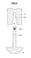
- FIG. 4 is a schematic view of how to attach the crimp contact onto the electrical lead according to the first or second embodiment of the present invention.
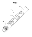
- FIG. 5 is a perspective view of a joint between the crimp contact and the electrical lead according to the first or second embodiment of the present invention.
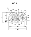
- FIG. 6 is a sectional view of the joint between the crimp contact and the electrical lead according to the first embodiment of the present invention.
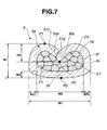
- FIG. 7 is a sectional view of the joint between the crimp contact and the electrical lead according to the second embodiment of the present invention.
- the first and second embodiments provide crimp contacts 5, each of which has one or more, e.g., three wire hold portions 5a extending axially and crimped to hold therein a plurality of, e.g., nineteen metal core wires 16 of an electrical lead 14.
- the wire hold portions 5a can be made of various metal materials such as a stainless alloy, nickel-chromium-iron alloy e.g. Inconel, beryllium copper alloy, copper-titanium alloy and copper-nickel-tin alloy. When there is a demand for heat resistance, the wire hold portions 5a may be suitably made of Inconel.
- the lead core wires 16 can be made of copper, tungsten, a tungsten-rhenium alloy and a mixture of silicon nitride or tungsten carbide. In the first and second embodiments, the lead core wires 16 are 0.2 mm in diameter.
- each of the wire hold portions 5a includes, when viewed in cross section perpendicular to the axial direction, a bottom wall 5b and a pair of side walls 5c rising from opposite sides of the bottom wall 5b and bent along an arcs in such a manner that the side walls 5c have their respective top ends 5d or 50c and 51c (located opposite to the bottom wall 5b) turned toward the bottom wall 5b and brought into contact with each other to form a wire accommodation space 5f in which the lead core wires 16 are enclosed by the bottom wall 5b and the side walls 5c.
- outer surfaces 5e of the side wall ends 5d are brought into contact with each other as shown in FIG. 6.
- an end face 51g of the side wall end 51 c is brought into contact with an outer surface 50e of the side wall end 50c as shown in FIG. 7.
- the dimensions of the wire hold portion 5a are controlled to satisfy the following equations (1) and (2): W ⁇ 1 ⁇ W ⁇ 2 / 2 / W ⁇ 3 ⁇ 1.2 H ⁇ 2 / H ⁇ 1 ⁇ 0.5
- W 1 is a maximum width of the wire hold portion 5a
- W2 is a maximum width of the wire accommodation space 5f
- W3 is a minimum thickness of the bottom wall 5b
- H1 is a maximum thickness of the wire hold portion 5a, i.e.
- H2 is a maximum distance from the outermost point P1 of the side wall 5c to a tip point P2 of the side wall end 5d, 50c or 51c along a thickness direction of the wire hold portion 5a.
- the maximum width W1 and the maximum width W2 indicate maximum horizontal dimensions when the wire hold portion 5a is viewed in cross section perpendicular to the axial direction with the bottom wall 5b placed in a horizontal orientation.
- the minimum thickness W3 indicates a minimum vertical dimension when the wire hold portion 5a is viewed in cross section perpendicular to the axial direction with the bottom wall 5b placed in a horizontal orientation.
- the maximum thickness (distance) H1 and the maximum distance H2 indicate maximum vertical dimensions when the wire hold portion 5a is viewed in cross section perpendicular to the axial direction with the bottom wall 5b placed in a horizontal orientation.
- the thickness of the bottom wall 5b is sufficiently large with respect to the thickness t(L), t(R) of the side walls 5c so that both of the side walls 5c properly rise from the bottom wall 5b.
- the side walls 5c are bent deeply so that the side wall ends 5d or 50c and 51c get sufficiently close to the bottom wall 5b when the equation (2) is satisfied.
- the wire hold portion 5a becomes able to limit displacements of the lead core wires 16 relative to the wire accommodation space 5f and to hold the lead core wires 16 tightly and securely by the bottom wall 5b and the side walls 5c regardless of the use or disuse of a lubricant in the crimping process and the kind of material of the crimp contact 5. It is therefore possible to prevent or minimize a widening of clearance between the wire hold portion 5a and the lead core wires 16 and avoid an increase in electrical resistance between the crimp contact 5 and the electrical lead 14 during the heating and cooling cycles of operation.
- the dimensions of the wire hold portion 5a are controlled to satisfy the following equation (3): 1 ⁇ W ⁇ 1 ⁇ W ⁇ 2 / 2 / W ⁇ 3
- the wire hold portion 5a becomes placed under a higher load to hold the lead core wires 16 more tightly and securely by the bottom and side walls 5b and 5c.
- the outer surfaces 5e of the respective side wall ends 5d are brought into contact with each other. With this configuration, the side wall ends 5d get closer to the bottom wall 5c.
- the wire hold portion 5a becomes thus able to hold the lead core wires 16 more tightly and securely by the bottom and side walls 5b and 5c without causing an increase in electrical resistance during the heating and cooling cycles of operation.
- the side wall ends 5d face the bottom wall 5b but are not in contact with the bottom wall 5b such that some of the lead core wires 16 exist between the bottom wall 5b and the side wall ends 15d.
- each of the inner surfaces of the bottom wall 5b and the side walls 5c (especially, the inner boundary surfaces C 1 between the bottom wall 5b and the side walls 5c and the inner surfaces C2 of the side wall ends 5d or 50c and 51c) is curved with a certain radius of curvature R so as to prevent or minimize a widening of clearance between the bottom and side walls 5b and 5c and the lead core wires 16.
- the curvature radius R is preferably made greater than or equal to the wire diameter of the lead core wires 16 as measured before the crimping process. This allows the wire hold portion 5a to hold the lead core wires 16 tightly and securely without causing an increase in electrical resistance during the heating and cooling cycles of operation.
- the wire hold portion 5a onto the lead core wires 16 in such a manner that all of the lead core wires 16 become deformed to change in dimension by 5% or more (i.e. the maximum wire diameter of the lead core wires 16 increases by 5% or more, or the minimum wire diameter of the lead wire cores 16 decreases by 5% or more). This allows the wire hold portion 5a to hold the lead core wires 16 more tightly and securely.
- the above crimp contact 5 can be provided as follows in each of the first and second embodiments.
- the crimp contact 5 is first prepared with uncrimped wire hold portions 25, 35 (to be completed into the respective wire hold portions 5a during the subsequent crimping process).
- each of the uncrimped wire hold portions 25 extends axially and includes, when viewed in cross section perpendicular to the axial direction, a bottom wall 25b and a pair of side walls 25c rising from opposite sides of the bottom wall 25b as shown in FIG. 3A.
- Top end regions 25d of the side walls 25c are previously inclined toward each other and made smaller in thickness than the other regions of the side walls 25c.
- the end regions 25d of the side walls 25c have respective tip points with a thickness of 0.1 mm (smaller than the diameter of the lead core wires 16) whereas the bottom wall 25b and the other regions of the side walls 25c have a thickness of 0.2 mm in the first embodiment.
- each of the uncrimped wire hold portions 35 extends axially and includes, when viewed in cross section perpendicular to the axial direction, a bottom wall 35b and a pair of side walls 35c rising from opposite sides of the bottom wall 35b as shown in FIG. 3B.
- Top end regions 35d of the side walls 35c are held substantially in parallel to each other and made substantially equal in thickness to the other regions of the side walls 35c. All of the bottom wall 35b and the side walls 35c (including their respective end regions 35d) are 0.2 mm in thickness in the second embodiment.
- the wire hold portions 25, 35 are crimped onto the lead core wires 16 using an anvil 22 and a crimper 24.
- the anvil 22 has a protrusion 22a extending upwardly from its bottom base, whereas the crimper 24 has a recess 24a fonned in its bottom end surface to engage with the anvil protrusion 22a.
- the crimping process is thus performed by arranging the wire hold portions 25, 35 on a top surface of the anvil protrusion 22a, placing the lead core wires 16 in the wire hold portions 25, 35 so as to surround the lead core wires 16 by the bottom walls 25b, 35b and the side walls 25c, 35c, moving the crimper 24 down to the anvil 22 and then pressing the wire hold portions 25, 35 between the anvil protrusion 22a and the crimper recess 24a.
- the crimp contact 5 is then completed.
- the sidewall end regions 25d When the side wall end regions 25d are inclined toward each other as is the case of the first embodiment, the sidewall end regions 25d can be easily guided by the crimper 24 closer to each other and be turned deeply toward the bottom wall 25b in the crimping process. Further, the side wall end regions 25d can be turned more deeply toward the bottom wall 25b in the crimping process when the side wall end regions 25d are made thinner as is the case of the first embodiment.
- the completed wire hold portion 5a becomes thus able to hold the lead core wires 16 more tightly and securely by the bottom wall 5b and the side walls 5c in the first embodiment regardless of the use or disuse of lubricant in the crimping process and the kind of material of the crimp contact 5.
- the above-configured crimp contacts 5 are applicable to various uses such as a gas sensor as shown in FIG. 1.
- the gas sensor is herein designed for use in an automotive exhaust system to detect the concentration of a specific gas component such as oxygen in automotive exhaust gas (as measurement gas).
- the gas sensor generally includes a sensor element 1, a heater element 6, a metallic sensor housing 2, metallic protective covers 3 and 4, metal packings 9a and 9b, a ceramic holder 10, a sealing power material 11 (of e.g. talc), a ceramic sleeve 12, a metal ring 13, a separator holder 17, a ceramic separator 18, a rubber grommet 19 and a filter unit 20 in addition to the crimp contacts 5 and the electrical leads 14 (hereinafter occasionally referred to as "crimp contacts 51, 52 and 53" and "electrical leads 14a, 14b and 14c, respectively).
- the sensor element 1 and the heater element 6 are arranged axially in the sensor housing 2.
- the sensor housing 2 is formed into a cylindrical shape to accommodate therein the sensor element 1 with a front end portion (sensor portion) of the sensor element 1 protruding from a front end of the sensor housing 2.
- a rear end of the sensor housing 2 is radially inwardly caulked so that the sensor element 1 is retained insulatively in the sensor housing 2 via the metal packings 9a and 9b, the ceramic holder 10, the sealing power material 11, the ceramic sleeve 12 and the metal ring 13.
- the sensor housing 2 has cylindrical bosses 2a and 2b formed on front and rear end portions of the sensor housing 2, respectively, a flange portion 2c formed between the bosses 2a and 2b and a male thread portion 2d formed between the boss 2a and the flange portion 2c. Further, a gasket G is fitted around the sensor housing 2 at a location between the flange portion 2c and the male thread portion 2d.
- the protective cover 3 is fixed at a front end thereof to the boss 2b of the sensor housing 2 so as to enclose and protect rear end portions (terminal portions) of the sensor element 1 and the heater element 6 protruding from the rear end of the sensor housing 2, the crimp contacts 51, 52 and 53 and the core wires 16 of the electrical leads 14a, 14b and 14c.
- the protective cover 4 has an outer cover member 4a fixed at a rear end thereof to an outer surface of the boss 2a of the sensor housing 2 and an inner cover member 4b fixed in the outer cover member 4a so as to enclose and protect the sensor portion of the sensor element 1.
- Gas holes 4c are formed in the cover members 4a and 4b, respectively, so that the measurement gas flows to the sensor portion of the sensor element 1 through the gas holes 4c (although the gas hole 4c in the inner cover member 4b is not shown in the drawings.)
- the ceramic separator 18 is provided with a flange portion 18a and arranged in a middle portion of the protective cover 3 with the separator holder 17 disposed between the protective cover 3 and the separator 18 at a front side of the separator flange portion 18a.
- the grommet 19 is formed into an annular shape with a through hole 19a and fixed in a rear portion of the protective cover 3 adjacently to the separator 18.
- the filter unit 20 is fitted in the grommet through hole 19a and has a metal cylindrical filter holder 20a and a filter 20b held by cylindrical and end surfaces of the holder 20a so as to provide gas communication between the inside of the protective cover 3 and the outside of the gas sensor via the filter 20b.
- the filter 20b can be made of e.g. polytetrafluoroethylene (PTFE).
- the electrical leads 14a, 14b and 14c are passed through the grommet 19 for connection of the sensor element 1 and the heater element 6 to an external device.
- the crimp contacts 51, 52 and 53 have front ends electrically connected to the terminal portions of the sensor element 1 and the heater element 6 within a front portion of the protective cover 3 and rear ends formed with the wire hold portions 5a and electrically connected to the core wires 16 of the electrical leads 14a, 14b and 14c within the separator 18, thereby allowing signal output from the sensor element 1 to the external device and energization of the heater element 6.
- the crimp contacts 5 are able to hold the lead core wires 16 tightly and securely without an increase in electrical resistance during the heating and cooling cycles of operation.
- the gas sensor With the use of such crimp contacts 5 (51, 52, 53) in the gas sensor, it becomes possible for the gas sensor to secure accurate signal output from the sensor element 1 to the external device as well as proper energization of the heater element 6 over a long period of time even when subjected to loads of the heating/cooling cycle operation of the gas sensor.
- Test samples of crimp contacts 5 of the first embodiment were prepared, each of which had three wire hold portions 5a crimped onto nineteen lead core wires 16 as shown in FIG. 5.
- the wire hold portions 5a were herein made of Inconel.
- the lead core wires 16 were made of pure copper and had a diameter of 0.2 mm before the crimping process.
- the crimping process was performed using an anvil 22 and a crimper 24 as shown in FIG. 4 without the application of a lubricant.
- Each of the completed wire hold portions 5a had a bottom wall 5b and side walls 5c, with top ends 5d of the respective side walls 5c turned toward the bottom wall 5b and outer surfaces 5e of the respective side wall ends 5d brought in contact with each other, to enclose the lead core wires 16 in a wire accommodation space 5f as shown in FIG. 6.
- one of the test samples of the crimp contacts 5 was cut at a joint between the wire hold portion 5a and the lead core wires 16 along a direction perpendicular to an axial direction of the wire hold portion 5a.
- the curvature radii R of inner surfaces of the bottom and side walls 5b and 5c and the maximum diameters of the lead core wires 16 were also determined by observation of the cross section of the wire hold portion 5a.
- Each of the inner surfaces of the bottom wall 5b and the side walls 5c (especially, the inner boundary surfaces C1 between the bottom wall 5b and the side walls 5c and the inner surfaces C2 of the side wall ends 5d) had a curvature radius R of 0.2 mm or larger, i.e., greater than or equal to the diameter of the lead core wires 16 as measured before the crimping process. Further, all of the lead core wires 16 had been deformed and had a maximum diameter of 0.21 mm or larger after the crimping process to show a change in dimension by 5% or more.
- the other test samples of the crimp contacts 5 were tested for electrical resistance ( ⁇ ) before and after performing 1000 cycles of heating at 300°C for 20 minutes and cooling at room temperatures for 10 minutes.
- the incidence of resistance increase was evaluated by 100 ⁇ A/N (%) where A is the number of the test samples in which the electrical resistance increased by 1 ⁇ or more during the heating and cooling cycles of operation; and N is the total number of the test samples.
- the evaluation result is also shown in TABLE.
- Test samples of crimp contacts 5 of the second embodiment were prepared, each of which had three wire hold portions 5a crimped onto nineteen lead core wires 16 as shown in FIG. 5.
- the wire hold portions 5a were made of Inconel.
- the lead core wires 16 were made of pure copper and had a diameter of 0.2 mm before the crimping process.
- the crimping process was performed using an anvil 22 and a crimper 24 as shown in FIG. 4 without the application of a lubricant.
- Each of the completed wire hold portions 5a had a bottom wall 5b and side walls 5c, with top ends 50c and 51c of the respective side walls 5c turned toward the bottom wall 5b and an end face 5 1 g of the side wall end 51c brought in contact with an outer surface 50e of the side wall end 50c, to enclose the lead core wires 16 in a wire accommodation space 5f as shown in FIG. 7.
- One of the test samples of the crimp contacts 5 was cut at a joint between the wire hold portion 5a and the lead core wires 16 along a direction perpendicular to an axial direction of the wire hold portion 5a for observation of the cross section of the wire hold portion 5a.
- the curvature radii R of inner surfaces of the bottom and side walls 5b and 5c and the maximum diameters of the lead core wires 16 were also determined by observation of the cross section of the wire hold portion 5a.
- Each of the inner surfaces of the bottom wall 5b and the side walls 5c (especially, the inner boundary surfaces C1 between the bottom wall 5b and the side walls 5c and the inner surfaces C2 of the side wall ends 50c and 51c) had a curvature radius R of 0.2 mm or larger, i.e., greater than or equal to the diameter of the lead core wires 16 as measured before the crimping process. Further, all of the lead core wires 16 had been deformed and had a maximum diameter of 0.21 mm or larger after the crimping process to show a change in dimension by 5% or more.
- test samples of the crimp contacts 5 were tested for electrical resistance before and after performing 1000 cycles of heating at 300°C for 20 minutes and cooling at room temperatures for 10 minutes, to evaluate the incidence of resistance increase by 100 ⁇ A/N (%) where A is the number of the test samples in which the electrical resistance increased by 1 ⁇ or more during the heating and cooling cycles of operation; and N is the total number of the test samples.
- A/N the number of the test samples in which the electrical resistance increased by 1 ⁇ or more during the heating and cooling cycles of operation
- N is the total number of the test samples.
- Test samples of crimp contacts were prepared in the same way as in Examples 1 and 2, except that each wire hold portion had a bottom wall and side walls crimped onto lead core wires with top end faces of the respective side walls brought into contact with each other. Then, dimension measurements, dimensional ratio calculations and resistance increase incidence evaluation were made on the test samples in the same way as in Examples 1 and 2. The measurement, calculation and evaluation results are shown in TABLE.
- Example 1 1.791 1.366 0.189 0.207 0.206 1.122 1.019 0.681 0.668 0.0
- Example 2 1.780 1.330 0.197 0.213 0.214 1.141 0.999 0.510 0.510 13.3
- Comparative Example 1.783 1.314 0.188 0.226 0.226 1.245 1.013 0.406 0.400 80.0
- each of the wire hold portions 5a of the crimp contacts 5 of the first and second embodiments which satisfies the equations of ⁇ (W1 - W2)/2 ⁇ /W3 ⁇ 1.2 and H2/H1 ⁇ 0.5, is capable of holding the lead core wires 16 tightly and securely under uniform and adequate loads to prevent or minimize a widening of clearance between the wire hold portion 5a and the lead core wires 16 and avoid an increase in electrical resistance during the heating and cooling cycles of operation and, in particular, the configuration of the wire hold portions 5a in which the outer end surfaces 5e of the side walls 5c are held into contact with each other as in the crimp contact 5 of the first embodiment provides a large effect in preventing increases in electrical resistance.
- the present invention has been described with reference to the first and second specific embodiments of the invention, the invention is not limited to the above-described embodiments. Various modification and variation of the embodiments described above will occur to those skilled in the art in light of the above teaching.
- the number of wire hold portions 5a in each crimp contact 5 is not limited to three although the crimp contact 5 is provided with three wire hold portions 5a in the first and second embodiments.
- the crimp contact 5 may alternatively be provided with one, two, or more than three wire hold portions 5a.
- the crimp contact 5 can hold the lead core wires 16 securely when provided with a plurality of wire hold portions 5a.
- the scope of the invention is defined with reference to the following claims.
Landscapes
- Engineering & Computer Science (AREA)
- Manufacturing & Machinery (AREA)
- Connections Effected By Soldering, Adhesion, Or Permanent Deformation (AREA)
- Measuring Oxygen Concentration In Cells (AREA)
Abstract
A crimp contact (5) includes a wire hold portion (5a) crimped onto and holding therein core wires (16) of an electrical lead (14). The wire hold portion has a bottom wall (5b) and a pair of side walls (5c) bent in such a manner as to bring ends (5d) of the side walls into contact with each other to define a wire accommodation space and satisfies the following equations: {(W1 - W2)/2}/W3 ¤ 1.2 and H2/H1 ¥ 0.5 where W1 is a maximum width of the wire hold portion; W2 is a maximum width of the wire accommodation space; W3 is a minimum thickness of the bottom wall; H1 is a maximum thickness of the wire hold portion; and H2 is a maximum distance from an outermost point of the side wall to a tip point of the side wall end along a thickness direction of the wire hold portion.
Description
- The present invention relates to a crimp contact and a gas sensor. Hereinafter, the term "front" refers to a sensing end side with respect to an axial direction of the gas sensor, and the term "rear" refers to a side opposite to the front side.
-
Japanese Laid-Open Patent Publication No. 64-041184 - In order for the gas sensor to secure accurate signal output over a long period of time, it is desirable that the wire hold portions of the crimp contact hold the lead core wires tightly so as to prevent or minimize a widening of clearance between the wire hold portions and the lead core wires and avoid an increase in electrical resistance between the crimp contact and the electrical lead during the heating and cooling cycles of operation of the gas sensor.
- In the above-mentioned conventional crimp contact, however, the wire hold portions are simply crimped onto the lead core wires with no specific dimension control through the application of a lubricant and thus may not be able to hold the lead core wires sufficiently tightly. It is further difficult in the conventional crimp contact to bend the wire hold portions adequately during the crimping process depending on the crimping process conditions (where the use of the lubricant is impractical in view of the crimp contact quality) and the crimp contact material so that the wire hold portions cannot hold the lead core wires tightly. As a result, there often arises an increase in electrical resistance between the conventional crimp contact and the electrical lead during the heating and cooling cycles of operation. The gas sensor with such a conventional crimp contact fails to secure accurate signal output over a long period of time.
- It is therefore an object of the present invention to provide a crimp contact capable of holding an electrical lead wire tightly and securely, regardless of the crimping process conditions (the use or disuse of a lubricant in the crimping process) and the crimp contact material, without causing an increase in electrical resistance between the crimp contact and the lead wire even when subjected to loads of the heating/cooling cycle operation.
- It is also an object of the present invention to provide a gas sensor having such a crimp contact to secure accurate signal output over a long period of time.
- According to a first aspect of the present invention, there is provided a crimp contact comprising a wire hold portion extending in an axial direction thereof and holding therein core wires of an electrical lead, the wire hold portion having, when viewed in cross section perpendicular to the axial direction, a bottom wall and a pair of side walls rising from opposite sides of the bottom wall and bent in such a manner as to turn top ends of the respective side walls toward the bottom wall and bring the top ends of the side walls into contact with each other to define a wire accommodation space in which the lead core wires are enclosed by the bottom wall and the side walls, and the wire hold portion being configured to satisfy the following equations: {(W1 - W2)/2}/W3 ≤ 1.2; and H2/H1 ≥ 0.5 where W1 is a maximum width of the wire hold portion; W2 is a maximum width of the wire accommodation space; W3 is a minimum thickness of the bottom wall; H1 is a maximum thickness of the wire hold portion; and H2 is a maximum distance from an outermost point of the side wall to a tip point of the top end of the side wall along a thickness direction of the wire hold portion.
- According to a second aspect of the present invention, there is provided a crimp contact comprising a wire hold portion extending in an axial direction thereof and holding therein core wires of an electrical lead, the wire hold portion having, when viewed in cross section perpendicular to the axial direction, a bottom wall and a pair of side walls rising from opposite sides of the bottom wall, with top ends of the respective side walls previously inclined toward each other, and bent in such a manner as to turn the previously inclined top ends of the side walls toward the bottom wall and bring one of the previously inclined top ends of the side walls into contact with the other of the previously top ends of the side walls to define a wire accommodation space in which the lead core wires are enclosed by the bottom wall and the side walls.
- According to a third aspect of the present invention, there is provided a gas sensor comprising: a cylindrical metallic housing; a sensor element disposed in the housing with at least a sensor portion of the sensor element protruding from a front end of the housing; a protective cover attached to a rear end of the housing; an electrical lead extending within the protective cover to produce a signal output from the sensor element to an external device; and a crimp contact connecting the a front end of electrical lead to a terminal portion of the sensor element, the crimp contact having a wire hold portion extending in an axial direction thereof and holding therein core wires of the electrical lead, the wire hold portion having, when viewed in cross section perpendicular to the axial direction, a bottom wall and a pair of side walls rising from opposite sides of the bottom wall and bent in such a manner as to turn top ends of the respective side walls toward the bottom wall and bring the top ends of the side walls into contact with each other to define a wire accommodation space in which the lead core wires are enclosed by the bottom wall and the side walls, and the wire hold portion being configured to satisfy the following equations: {(W1 - W2)/2}/W3 ≤ 1.2; and H2/H1 ≥ 0.5 where W1 is a maximum width of the wire hold portion; W2 is a maximum width of the wire accommodation space; W3 is a minimum thickness of the bottom wall; H1 is a maximum thickness of the wire hold portion; and H2 is a maximum distance from an outermost point of the side wall to a tip point of the top end of the side wall along a thickness direction of the wire hold portion.
- According to a fourth aspect of the present invention, there is provided a gas sensor comprising: a cylindrical metallic housing; a sensor element disposed in the housing with at least a sensor portion of the sensor element protruding from a front end of the housing; a protective cover attached to a rear end of the housing; an electrical lead extending within the protective cover to produce a signal output from the sensor element to an external device; and a crimp contact connecting a front end of the electrical lead to a terminal portion of the sensor element, the crimp contact having a wire hold portion extending in an axial direction thereof and holding therein core wires of the electrical lead, and the wire hold portion having, when viewed in cross section perpendicular to the axial direction, a bottom wall and a pair of side walls rising from opposite sides of the bottom wall, with top ends of the respective side walls previously inclined toward each other, and bent in such a manner as to turn the previously inclined top ends of the side walls toward the bottom wall and bring one of the previously inclined top ends of the side walls into contact with the other of the previously inclined top ends of the side walls to define a wire accommodation space in which the lead core wires are enclosed by the bottom wall and the side walls.
- The other objects and features of the invention will also become understood from the following description.
- FIG. 1 is a sectional view of a gas sensor according to one exemplary embodiment of the present invention.
- FIG. 2 is a perspective view of a crimp contact formed with wire hold portions, before being crimped onto the core wires of an electrical lead, according to a first or second embodiment of the present invention.
- FIG. 3A is a sectional view of the wire hold portion of the crimp contact, before being crimped onto the lead core wires, according to the first embodiment of the present invention.
- FIG. 3B is a sectional view of the wire hold portion of the crimp contact, before being crimped onto the lead core wires, according to the second embodiment of the present invention.
- FIG. 4 is a schematic view of how to attach the crimp contact onto the electrical lead according to the first or second embodiment of the present invention.
- FIG. 5 is a perspective view of a joint between the crimp contact and the electrical lead according to the first or second embodiment of the present invention.
- FIG. 6 is a sectional view of the joint between the crimp contact and the electrical lead according to the first embodiment of the present invention.
- FIG. 7 is a sectional view of the joint between the crimp contact and the electrical lead according to the second embodiment of the present invention.
- The present invention will be described below in detail with reference to the following first and second embodiments, in which like parts and portions are designated by like reference numerals.
- Referring to FIG. 5, the first and second embodiments provide
crimp contacts 5, each of which has one or more, e.g., three wire holdportions 5a extending axially and crimped to hold therein a plurality of, e.g., nineteenmetal core wires 16 of anelectrical lead 14. - The wire hold
portions 5a can be made of various metal materials such as a stainless alloy, nickel-chromium-iron alloy e.g. Inconel, beryllium copper alloy, copper-titanium alloy and copper-nickel-tin alloy. When there is a demand for heat resistance, the wire holdportions 5a may be suitably made of Inconel. Thelead core wires 16 can be made of copper, tungsten, a tungsten-rhenium alloy and a mixture of silicon nitride or tungsten carbide. In the first and second embodiments, thelead core wires 16 are 0.2 mm in diameter. - As shown in FIGS. 6 and 7, each of the wire hold
portions 5a includes, when viewed in cross section perpendicular to the axial direction, abottom wall 5b and a pair ofside walls 5c rising from opposite sides of thebottom wall 5b and bent along an arcs in such a manner that theside walls 5c have theirrespective top ends bottom wall 5b) turned toward thebottom wall 5b and brought into contact with each other to form awire accommodation space 5f in which thelead core wires 16 are enclosed by thebottom wall 5b and theside walls 5c. More specifically, in the first embodiment,outer surfaces 5e of theside wall ends 5d (other than end faces of theside wall ends 5d and inner surfaces of theside wall ends 5d defining a part of the wire accommodation space 15f) are brought into contact with each other as shown in FIG. 6. In the second embodiment, by contrast, anend face 51g of theside wall end 51 c is brought into contact with anouter surface 50e of theside wall end 50c as shown in FIG. 7. - In both of the first and second embodiments, the dimensions of the
wire hold portion 5a are controlled to satisfy the following equations (1) and (2):

whereW 1 is a maximum width of thewire hold portion 5a; W2 is a maximum width of thewire accommodation space 5f; W3 is a minimum thickness of thebottom wall 5b; H1 is a maximum thickness of thewire hold portion 5a, i.e. a maximum distance between an outermost (starting) point P1 of theside wall 5c and an outermost (starting) point P3 of thebottom wall 5b; and H2 is a maximum distance from the outermost point P1 of theside wall 5c to a tip point P2 of theside wall end portion 5a. - Herein, the maximum width W1 and the maximum width W2 indicate maximum horizontal dimensions when the
wire hold portion 5a is viewed in cross section perpendicular to the axial direction with thebottom wall 5b placed in a horizontal orientation. The minimum thickness W3 indicates a minimum vertical dimension when thewire hold portion 5a is viewed in cross section perpendicular to the axial direction with thebottom wall 5b placed in a horizontal orientation. Further, the maximum thickness (distance) H1 and the maximum distance H2 indicate maximum vertical dimensions when thewire hold portion 5a is viewed in cross section perpendicular to the axial direction with thebottom wall 5b placed in a horizontal orientation. - When the equation (1) is satisfied, the thickness of the
bottom wall 5b is sufficiently large with respect to the thickness t(L), t(R) of theside walls 5c so that both of theside walls 5c properly rise from thebottom wall 5b. Theside walls 5c are bent deeply so that the side wall ends 5d or 50c and 51c get sufficiently close to thebottom wall 5b when the equation (2) is satisfied. With such a configuration, thewire hold portion 5a becomes able to limit displacements of thelead core wires 16 relative to thewire accommodation space 5f and to hold thelead core wires 16 tightly and securely by thebottom wall 5b and theside walls 5c regardless of the use or disuse of a lubricant in the crimping process and the kind of material of thecrimp contact 5. It is therefore possible to prevent or minimize a widening of clearance between the wire holdportion 5a and thelead core wires 16 and avoid an increase in electrical resistance between thecrimp contact 5 and theelectrical lead 14 during the heating and cooling cycles of operation. - Preferably, the dimensions of the
wire hold portion 5a are controlled to satisfy the following equation (3):
When the equation (3) is satisfied, thewire hold portion 5a becomes placed under a higher load to hold thelead core wires 16 more tightly and securely by the bottom andside walls - It is preferable that, as is the case with the first embodiment, the
outer surfaces 5e of the respectiveside wall ends 5d are brought into contact with each other. With this configuration, theside wall ends 5d get closer to thebottom wall 5c. The wire holdportion 5a becomes thus able to hold thelead core wires 16 more tightly and securely by the bottom andside walls side wall ends 5d face thebottom wall 5b but are not in contact with thebottom wall 5b such that some of thelead core wires 16 exist between thebottom wall 5b and the side wall ends 15d. - It is also preferable that each of the inner surfaces of the
bottom wall 5b and theside walls 5c (especially, the innerboundary surfaces C 1 between thebottom wall 5b and theside walls 5c and the inner surfaces C2 of theside wall ends side walls lead core wires 16. In order to prevent or minimize clearance between the bottom andside walls lead core wires 16 without fail, the curvature radius R is preferably made greater than or equal to the wire diameter of thelead core wires 16 as measured before the crimping process. This allows the wire holdportion 5a to hold thelead core wires 16 tightly and securely without causing an increase in electrical resistance during the heating and cooling cycles of operation. - It is further preferable to crimp the wire hold
portion 5a onto thelead core wires 16 in such a manner that all of thelead core wires 16 become deformed to change in dimension by 5% or more (i.e. the maximum wire diameter of thelead core wires 16 increases by 5% or more, or the minimum wire diameter of thelead wire cores 16 decreases by 5% or more). This allows the wire holdportion 5a to hold thelead core wires 16 more tightly and securely. - The
above crimp contact 5 can be provided as follows in each of the first and second embodiments. - As shown in FIG. 2, the
crimp contact 5 is first prepared with uncrimped wire holdportions 25, 35 (to be completed into the respective wire holdportions 5a during the subsequent crimping process). - In the first embodiment, each of the uncrimped wire hold
portions 25 extends axially and includes, when viewed in cross section perpendicular to the axial direction, abottom wall 25b and a pair ofside walls 25c rising from opposite sides of thebottom wall 25b as shown in FIG. 3A.Top end regions 25d of theside walls 25c (to be formed into theside wall ends 5d) are previously inclined toward each other and made smaller in thickness than the other regions of theside walls 25c. Theend regions 25d of theside walls 25c have respective tip points with a thickness of 0.1 mm (smaller than the diameter of the lead core wires 16) whereas thebottom wall 25b and the other regions of theside walls 25c have a thickness of 0.2 mm in the first embodiment. - In the second embodiment, each of the uncrimped wire hold
portions 35 extends axially and includes, when viewed in cross section perpendicular to the axial direction, abottom wall 35b and a pair ofside walls 35c rising from opposite sides of thebottom wall 35b as shown in FIG. 3B.Top end regions 35d of theside walls 35c (to be formed into the side wall ends 50c and 51c) are held substantially in parallel to each other and made substantially equal in thickness to the other regions of theside walls 35c. All of thebottom wall 35b and theside walls 35c (including theirrespective end regions 35d) are 0.2 mm in thickness in the second embodiment. - As shown in FIG. 4, the
wire hold portions lead core wires 16 using ananvil 22 and acrimper 24. Theanvil 22 has aprotrusion 22a extending upwardly from its bottom base, whereas thecrimper 24 has arecess 24a fonned in its bottom end surface to engage with theanvil protrusion 22a. The crimping process is thus performed by arranging thewire hold portions anvil protrusion 22a, placing thelead core wires 16 in thewire hold portions lead core wires 16 by thebottom walls side walls crimper 24 down to theanvil 22 and then pressing thewire hold portions anvil protrusion 22a and thecrimper recess 24a. Thecrimp contact 5 is then completed. - When the side
wall end regions 25d are inclined toward each other as is the case of the first embodiment, thesidewall end regions 25d can be easily guided by thecrimper 24 closer to each other and be turned deeply toward thebottom wall 25b in the crimping process. Further, the sidewall end regions 25d can be turned more deeply toward thebottom wall 25b in the crimping process when the sidewall end regions 25d are made thinner as is the case of the first embodiment. The completedwire hold portion 5a becomes thus able to hold thelead core wires 16 more tightly and securely by thebottom wall 5b and theside walls 5c in the first embodiment regardless of the use or disuse of lubricant in the crimping process and the kind of material of thecrimp contact 5. - The above-configured
crimp contacts 5 are applicable to various uses such as a gas sensor as shown in FIG. 1. By way of example, the gas sensor is herein designed for use in an automotive exhaust system to detect the concentration of a specific gas component such as oxygen in automotive exhaust gas (as measurement gas). - The gas sensor generally includes a
sensor element 1, aheater element 6, ametallic sensor housing 2, metallicprotective covers metal packings ceramic holder 10, a sealing power material 11 (of e.g. talc), aceramic sleeve 12, ametal ring 13, aseparator holder 17, aceramic separator 18, arubber grommet 19 and afilter unit 20 in addition to thecrimp contacts 5 and the electrical leads 14 (hereinafter occasionally referred to as "crimpcontacts electrical leads - The
sensor element 1 and theheater element 6 are arranged axially in thesensor housing 2. - The
sensor housing 2 is formed into a cylindrical shape to accommodate therein thesensor element 1 with a front end portion (sensor portion) of thesensor element 1 protruding from a front end of thesensor housing 2. A rear end of thesensor housing 2 is radially inwardly caulked so that thesensor element 1 is retained insulatively in thesensor housing 2 via themetal packings ceramic holder 10, the sealingpower material 11, theceramic sleeve 12 and themetal ring 13. Thesensor housing 2 hascylindrical bosses sensor housing 2, respectively, aflange portion 2c formed between thebosses male thread portion 2d formed between theboss 2a and theflange portion 2c. Further, a gasket G is fitted around thesensor housing 2 at a location between theflange portion 2c and themale thread portion 2d. - The
protective cover 3 is fixed at a front end thereof to theboss 2b of thesensor housing 2 so as to enclose and protect rear end portions (terminal portions) of thesensor element 1 and theheater element 6 protruding from the rear end of thesensor housing 2, thecrimp contacts core wires 16 of theelectrical leads - The
protective cover 4 has anouter cover member 4a fixed at a rear end thereof to an outer surface of theboss 2a of thesensor housing 2 and aninner cover member 4b fixed in theouter cover member 4a so as to enclose and protect the sensor portion of thesensor element 1. Gas holes 4c are formed in thecover members sensor element 1 through the gas holes 4c (although thegas hole 4c in theinner cover member 4b is not shown in the drawings.) - The
ceramic separator 18 is provided with aflange portion 18a and arranged in a middle portion of theprotective cover 3 with theseparator holder 17 disposed between theprotective cover 3 and theseparator 18 at a front side of theseparator flange portion 18a. - The
grommet 19 is formed into an annular shape with a throughhole 19a and fixed in a rear portion of theprotective cover 3 adjacently to theseparator 18. - The
filter unit 20 is fitted in the grommet throughhole 19a and has a metalcylindrical filter holder 20a and afilter 20b held by cylindrical and end surfaces of theholder 20a so as to provide gas communication between the inside of theprotective cover 3 and the outside of the gas sensor via thefilter 20b. Thefilter 20b can be made of e.g. polytetrafluoroethylene (PTFE). - The
electrical leads grommet 19 for connection of thesensor element 1 and theheater element 6 to an external device. - The
crimp contacts sensor element 1 and theheater element 6 within a front portion of theprotective cover 3 and rear ends formed with thewire hold portions 5a and electrically connected to thecore wires 16 of theelectrical leads separator 18, thereby allowing signal output from thesensor element 1 to the external device and energization of theheater element 6. - As explained above, the crimp contacts 5 (51, 52, 53) are able to hold the
lead core wires 16 tightly and securely without an increase in electrical resistance during the heating and cooling cycles of operation. With the use of such crimp contacts 5 (51, 52, 53) in the gas sensor, it becomes possible for the gas sensor to secure accurate signal output from thesensor element 1 to the external device as well as proper energization of theheater element 6 over a long period of time even when subjected to loads of the heating/cooling cycle operation of the gas sensor. - The present invention will be described in more detail by reference to the following examples. It should be however noted that the following examples are only illustrative and not intended to limit the invention thereto.
- Test samples of
crimp contacts 5 of the first embodiment were prepared, each of which had threewire hold portions 5a crimped onto nineteenlead core wires 16 as shown in FIG. 5. Thewire hold portions 5a were herein made of Inconel. Thelead core wires 16 were made of pure copper and had a diameter of 0.2 mm before the crimping process. The crimping process was performed using ananvil 22 and acrimper 24 as shown in FIG. 4 without the application of a lubricant. Each of the completedwire hold portions 5a had abottom wall 5b andside walls 5c, withtop ends 5d of therespective side walls 5c turned toward thebottom wall 5b andouter surfaces 5e of the respective side wall ends 5d brought in contact with each other, to enclose thelead core wires 16 in awire accommodation space 5f as shown in FIG. 6. - For cross section observation of the
wire hold portion 5a, one of the test samples of thecrimp contacts 5 was cut at a joint between thewire hold portion 5a and thelead core wires 16 along a direction perpendicular to an axial direction of thewire hold portion 5a. - Various dimension measurements were made on the cross section of the
wire hold portion 5a, so as to determine a maximum width W1 of thewire hold portion 5a, a maximum width W2 of thewire accommodation space 5f, a minimum thickness W3 of thebottom wall 5b, a thickness t(R) of theright side wall 5c along an extension line of the width W2, a thickness t(L) of theleft side wall 5c along an extension line of the width W2, a maximum thickness H1 of thewire hold portion 5a and a maximum distance H2 from an outermosttop point P 1 of theside wall 5c to a tip point P2 of theside wall end 5d along a thickness direction of thewire hold portion 5a as indicated in FIG. 6. The dimensional ratios of {(W1 - W2)/2}/W3 and H2/H1 were calculated from these measurement values W1, W2, W3, H1 and H2. The measurement and calculation results are shown in TABLE. - The curvature radii R of inner surfaces of the bottom and
side walls lead core wires 16 were also determined by observation of the cross section of thewire hold portion 5a. Each of the inner surfaces of thebottom wall 5b and theside walls 5c (especially, the inner boundary surfaces C1 between thebottom wall 5b and theside walls 5c and the inner surfaces C2 of the side wall ends 5d) had a curvature radius R of 0.2 mm or larger, i.e., greater than or equal to the diameter of thelead core wires 16 as measured before the crimping process. Further, all of thelead core wires 16 had been deformed and had a maximum diameter of 0.21 mm or larger after the crimping process to show a change in dimension by 5% or more. - The other test samples of the
crimp contacts 5 were tested for electrical resistance (Ω) before and after performing 1000 cycles of heating at 300°C for 20 minutes and cooling at room temperatures for 10 minutes. The incidence of resistance increase was evaluated by 100 × A/N (%) where A is the number of the test samples in which the electrical resistance increased by 1 Ω or more during the heating and cooling cycles of operation; and N is the total number of the test samples. The evaluation result is also shown in TABLE. - Test samples of
crimp contacts 5 of the second embodiment were prepared, each of which had threewire hold portions 5a crimped onto nineteenlead core wires 16 as shown in FIG. 5. Thewire hold portions 5a were made of Inconel. Thelead core wires 16 were made of pure copper and had a diameter of 0.2 mm before the crimping process. The crimping process was performed using ananvil 22 and acrimper 24 as shown in FIG. 4 without the application of a lubricant. Each of the completedwire hold portions 5a had abottom wall 5b andside walls 5c, with top ends 50c and 51c of therespective side walls 5c turned toward thebottom wall 5b and anend face 5 1 g of theside wall end 51c brought in contact with anouter surface 50e of theside wall end 50c, to enclose thelead core wires 16 in awire accommodation space 5f as shown in FIG. 7. - One of the test samples of the
crimp contacts 5 was cut at a joint between thewire hold portion 5a and thelead core wires 16 along a direction perpendicular to an axial direction of thewire hold portion 5a for observation of the cross section of thewire hold portion 5a. - Various dimensions W1, W2, W3, t(L), t(R), H1 and H2 were measured as indicated in FIG. 7, and then, the dimensional ratios of {(W1 - W2)/2}/W3 and H2 /H1 were calculated from these measurement values W1, W2, W3, H1 and H2. The measurement and calculation results are shown in TABLE.
- The curvature radii R of inner surfaces of the bottom and
side walls lead core wires 16 were also determined by observation of the cross section of thewire hold portion 5a. Each of the inner surfaces of thebottom wall 5b and theside walls 5c (especially, the inner boundary surfaces C1 between thebottom wall 5b and theside walls 5c and the inner surfaces C2 of the side wall ends 50c and 51c) had a curvature radius R of 0.2 mm or larger, i.e., greater than or equal to the diameter of thelead core wires 16 as measured before the crimping process. Further, all of thelead core wires 16 had been deformed and had a maximum diameter of 0.21 mm or larger after the crimping process to show a change in dimension by 5% or more. - The other test samples of the
crimp contacts 5 were tested for electrical resistance before and after performing 1000 cycles of heating at 300°C for 20 minutes and cooling at room temperatures for 10 minutes, to evaluate the incidence of resistance increase by 100 × A/N (%) where A is the number of the test samples in which the electrical resistance increased by 1 Ω or more during the heating and cooling cycles of operation; and N is the total number of the test samples. The evaluation result is also shown in TABLE. - Test samples of crimp contacts were prepared in the same way as in Examples 1 and 2, except that each wire hold portion had a bottom wall and side walls crimped onto lead core wires with top end faces of the respective side walls brought into contact with each other. Then, dimension measurements, dimensional ratio calculations and resistance increase incidence evaluation were made on the test samples in the same way as in Examples 1 and 2. The measurement, calculation and evaluation results are shown in TABLE.
TABLE W1 (mm) W2 (mm) W3 (mm) t(L) (mm) t(R) (mm) {(W1-W2)/2}/W3 H1 (mm) H2 (mm) H2/H1 Incidence of resistance increase (%) Example 1 1.791 1.366 0.189 0.207 0.206 1.122 1.019 0.681 0.668 0.0 Example 2 1.780 1.330 0.197 0.213 0.214 1.141 0.999 0.510 0.510 13.3 Comparative Example 1.783 1.314 0.188 0.226 0.226 1.245 1.013 0.406 0.400 80.0 - As is evident from TABLE, the incident of resistance increase was much lower in each of Examples 1 and 2 than in Comparative Example.
- It has thus been shown that each of the
wire hold portions 5a of thecrimp contacts 5 of the first and second embodiments, which satisfies the equations of {(W1 - W2)/2}/W3 ≤ 1.2 and H2/H1 ≥ 0.5, is capable of holding thelead core wires 16 tightly and securely under uniform and adequate loads to prevent or minimize a widening of clearance between thewire hold portion 5a and thelead core wires 16 and avoid an increase in electrical resistance during the heating and cooling cycles of operation and, in particular, the configuration of thewire hold portions 5a in which theouter end surfaces 5e of theside walls 5c are held into contact with each other as in thecrimp contact 5 of the first embodiment provides a large effect in preventing increases in electrical resistance. - The entire contents of
Japanese Patent Application No. 2005-186081 (filed on June 27, 2005 - Although the present invention has been described with reference to the first and second specific embodiments of the invention, the invention is not limited to the above-described embodiments. Various modification and variation of the embodiments described above will occur to those skilled in the art in light of the above teaching. For example, the number of
wire hold portions 5a in eachcrimp contact 5 is not limited to three although thecrimp contact 5 is provided with threewire hold portions 5a in the first and second embodiments. Thecrimp contact 5 may alternatively be provided with one, two, or more than threewire hold portions 5a. Generally, thecrimp contact 5 can hold thelead core wires 16 securely when provided with a plurality ofwire hold portions 5a. The scope of the invention is defined with reference to the following claims.
Claims (9)
- A crimp contact (5) comprising a wire hold portion (5a) extending in an axial direction thereof and holding therein core wires (16) of an electrical lead (14),
the wire hold portion (5a) having, when viewed in cross section perpendicular to the axial direction, a bottom wall (5b) and a pair of side walls (5c) rising from opposite sides of the bottom wall (5b) and bent in such a manner as to turn top ends (5d; 50c, 51c) of the respective side walls (5c) toward the bottom wall (5b) and bring the top ends (5d; 50c, 51c) of the side walls (5c) into contact with each other to define a wire accommodation space (5f) in which the lead core wires (16) are enclosed by the bottom wall (5b) and the side walls (5c), and the wire hold portion (5a) being configured to satisfy the following equations:

where W1 is a maximum width of the wire hold portion (5a); W2 is a maximum width of the wire accommodation space (5f); W3 is a minimum thickness of the bottom wall (5b); H1 is a maximum thickness of the wire hold portion (5a); and H2 is a maximum distance from an outermost point (P1) of the side wall (5c) to a tip point (P2) of the top end (5d; 50c, 51c) of the side wall (5c) along a thickness direction of the wire hold portion (5a). - The crimp contact (5) according to claim 1, wherein the wire hold portion (5a) is configured to satisfy the following equation: 1 < {(W1 - W2)/2}/W3.
- A crimp contact (5) comprising a wire hold portion (5a) extending in an axial direction thereof and holding therein core wires (16) of an electrical lead (14),
the wire hold portion (5a) having, when viewed in cross section perpendicular to the axial direction, a bottom wall (5b) and a pair of side walls (5c) rising from opposite sides of the bottom wall (5b), with top ends (5d) of the respective side walls (5c) previously inclined toward each other, and bent in such a manner as to turn the previously inclined top ends (5d) of the side walls (5c) toward the bottom wall (5b) and bring one of the previously inclined top ends (5d) of the side walls (5c) into contact with the other of the previously top ends (5d) of the side walls (5c) to define a wire accommodation space (5f) in which the lead core wires (16) are enclosed by the bottom wall (5b) and the side walls (5c). - The crimp contact (5) according to any one of claims 1 to 3, wherein the ends (5d) of the side walls (5c) have respective outer surfaces (5e) held into contact with each other.
- The crimp contact (5) according to claim 3 or 5, wherein the ends (5d) of the side walls (5c)are thinner than any other regions of the side walls (5c).
- The crimp contact (5) according to any one of claims 1 to 5, wherein each of the bottom wall (5b) and the side walls (5c) has an inner surface (C1; C2) curved with a radius of curvature.
- The crimp contact (5) according to claim 6, wherein said radius of curvature is greater than or equal to a diameter of the lead core wires (16) as measured before the wire hold portion (5a) is crimped onto the lead core wires (16).
- The crimp contact (5) according to any one of claims 1 to 7, wherein the wire hold portion (5a) is crimped onto the lead core wires (16) in such a manner that all of the lead core wires (16) become deformed to change in dimension by 5% or more.
- A gas sensor comprising:a cylindrical metallic housing (2);a sensor element (1) disposed in the housing (2) with at least a sensor portion of the sensor element (1) protruding from a front end of the housing (2);a protective cover (3) attached to a rear end of the housing (2);an electrical lead (14) extending within the protective cover (3) to produce a signal output from the sensor element (1) to an external device; anda crimp contact (5) according to any one of claims 1 to 8 to connect a front end of the electrical lead (14) to a terminal portion of the sensor element (1).
Applications Claiming Priority (1)
| Application Number | Priority Date | Filing Date | Title |
|---|---|---|---|
| JP2005186081A JP2007005202A (en) | 2005-06-27 | 2005-06-27 | Crimp terminal and gas sensor |
Publications (1)
| Publication Number | Publication Date |
|---|---|
| EP1739791A1 true EP1739791A1 (en) | 2007-01-03 |
Family
ID=37074638
Family Applications (1)
| Application Number | Title | Priority Date | Filing Date |
|---|---|---|---|
| EP06013129A Withdrawn EP1739791A1 (en) | 2005-06-27 | 2006-06-26 | Crimp contact and gas sensor |
Country Status (5)
| Country | Link |
|---|---|
| US (1) | US20060288757A1 (en) |
| EP (1) | EP1739791A1 (en) |
| JP (1) | JP2007005202A (en) |
| CN (1) | CN1893186A (en) |
| DE (1) | DE202006019985U1 (en) |
Cited By (1)
| Publication number | Priority date | Publication date | Assignee | Title |
|---|---|---|---|---|
| EP2784877A1 (en) * | 2013-03-29 | 2014-10-01 | NGK Insulators, Ltd. | Crimp terminal, crimp body, and method for manufacturing crimp body |
Families Citing this family (8)
| Publication number | Priority date | Publication date | Assignee | Title |
|---|---|---|---|---|
| CN101315346B (en) * | 2008-05-16 | 2013-02-06 | 联合汽车电子有限公司 | Gas sensor |
| EP2458685B1 (en) * | 2010-11-26 | 2015-07-22 | Delphi Technologies, Inc. | Cable connector |
| JP5689710B2 (en) * | 2011-03-02 | 2015-03-25 | 木谷電器株式会社 | Electrical connection structure of terminal box to solar cell module |
| JP5995765B2 (en) * | 2013-03-27 | 2016-09-21 | 日本特殊陶業株式会社 | Gas sensor |
| JP6709806B2 (en) * | 2018-01-18 | 2020-06-17 | 矢崎総業株式会社 | Crimper |
| US12136790B2 (en) * | 2018-10-15 | 2024-11-05 | Beijing Const Instruments Technology Inc. | Crimp terminal, crimp terminal module, terminal box and tester |
| JP7402419B2 (en) * | 2020-09-16 | 2023-12-21 | 住友電装株式会社 | wire with terminal |
| JP7447749B2 (en) * | 2020-09-16 | 2024-03-12 | 住友電装株式会社 | Electric wire with terminal |
Citations (2)
| Publication number | Priority date | Publication date | Assignee | Title |
|---|---|---|---|---|
| US4812138A (en) * | 1987-02-12 | 1989-03-14 | Yazaki Corporation | Connector terminal |
| EP1191631A2 (en) * | 2000-09-22 | 2002-03-27 | Yazaki Corporation | Method of connecting terminal to wire |
Family Cites Families (8)
| Publication number | Priority date | Publication date | Assignee | Title |
|---|---|---|---|---|
| JPH0231738Y2 (en) * | 1986-09-24 | 1990-08-28 | ||
| JPH01107484A (en) * | 1987-10-21 | 1989-04-25 | Hitachi Lighting Ltd | Attachment of lead wire under pressure |
| JPH0992351A (en) * | 1995-09-21 | 1997-04-04 | Japan Aviation Electron Ind Ltd | Contacts and connectors for cables with the contacts |
| JP3625627B2 (en) * | 1996-10-14 | 2005-03-02 | 日本特殊陶業株式会社 | Ceramic applied electronic device used under high temperature and manufacturing method thereof |
| DE19728370A1 (en) * | 1997-07-03 | 1999-01-07 | Bosch Gmbh Robert | Cable bushing sealing device for at least one connecting cable esp. of gas sensor |
| JPH11260431A (en) * | 1998-03-11 | 1999-09-24 | Ngk Spark Plug Co Ltd | Connecting terminal |
| JP2003272728A (en) * | 2002-03-12 | 2003-09-26 | Yazaki Corp | Wire connection method |
| JP4436053B2 (en) * | 2003-02-13 | 2010-03-24 | 矢崎総業株式会社 | Crimping terminal state estimation device and crimping terminal pass / fail judgment device |
-
2005
- 2005-06-27 JP JP2005186081A patent/JP2007005202A/en active Pending
-
2006
- 2006-06-26 EP EP06013129A patent/EP1739791A1/en not_active Withdrawn
- 2006-06-26 DE DE202006019985U patent/DE202006019985U1/en not_active Expired - Lifetime
- 2006-06-27 US US11/474,949 patent/US20060288757A1/en not_active Abandoned
- 2006-06-27 CN CNA2006100941462A patent/CN1893186A/en active Pending
Patent Citations (2)
| Publication number | Priority date | Publication date | Assignee | Title |
|---|---|---|---|---|
| US4812138A (en) * | 1987-02-12 | 1989-03-14 | Yazaki Corporation | Connector terminal |
| EP1191631A2 (en) * | 2000-09-22 | 2002-03-27 | Yazaki Corporation | Method of connecting terminal to wire |
Cited By (2)
| Publication number | Priority date | Publication date | Assignee | Title |
|---|---|---|---|---|
| EP2784877A1 (en) * | 2013-03-29 | 2014-10-01 | NGK Insulators, Ltd. | Crimp terminal, crimp body, and method for manufacturing crimp body |
| US9257757B2 (en) | 2013-03-29 | 2016-02-09 | Ngk Insulators, Ltd. | Crimp terminal, crimp body, and method for manufacturing crimp body |
Also Published As
| Publication number | Publication date |
|---|---|
| JP2007005202A (en) | 2007-01-11 |
| US20060288757A1 (en) | 2006-12-28 |
| DE202006019985U1 (en) | 2007-08-02 |
| CN1893186A (en) | 2007-01-10 |
Similar Documents
| Publication | Publication Date | Title |
|---|---|---|
| US8398837B2 (en) | Sensor | |
| US8177590B2 (en) | Crimping terminal and method of manufacturing terminal-provided wire | |
| US6527573B2 (en) | Slide contact electrical connector | |
| US10203301B2 (en) | Gas sensor | |
| US20240272115A1 (en) | Gas sensor | |
| US20200014130A1 (en) | Terminal metal fitting and terminal-attached electric wire | |
| US11359995B2 (en) | Gas sensor | |
| US20060288757A1 (en) | Crimp contact and gas sensor | |
| US20140295715A1 (en) | Contact member and manufacturing method of sensor | |
| US9257757B2 (en) | Crimp terminal, crimp body, and method for manufacturing crimp body | |
| US9151728B2 (en) | Gas sensor | |
| US8721855B2 (en) | Crimp contact, crimp contact with an electrical lead, gas sensor including said crimp contact and method for manufacturing said gas sensor | |
| EP1703278A1 (en) | Gas sensor production method and gas sensor | |
| US20130205872A1 (en) | Gas sensor and subassembly unit therefor | |
| US8272901B2 (en) | Crimp contacts and electrical connector assemblies including the same | |
| JP2022125051A (en) | Reference jig | |
| US9793617B2 (en) | Electrical wire-connecting structure and method for manufacturing electrical wire-connecting structure | |
| US20210041393A1 (en) | Sensor and method for manufacturing same | |
| JP6786312B2 (en) | Crimping terminal | |
| JP2012154773A (en) | Gas sensor | |
| JP6826907B2 (en) | Gas sensor | |
| JP2005072007A (en) | Measuring sensor for identifying the physical properties of the measuring gas | |
| US10014665B2 (en) | Spark plug | |
| US20210018461A1 (en) | Gas sensor and method of manufacturing the same | |
| JP6324267B2 (en) | Method for manufacturing crimp connection structure |
Legal Events
| Date | Code | Title | Description |
|---|---|---|---|
| PUAI | Public reference made under article 153(3) epc to a published international application that has entered the european phase |
Free format text: ORIGINAL CODE: 0009012 |
|
| AK | Designated contracting states |
Kind code of ref document: A1 Designated state(s): AT BE BG CH CY CZ DE DK EE ES FI FR GB GR HU IE IS IT LI LT LU LV MC NL PL PT RO SE SI SK TR |
|
| AX | Request for extension of the european patent |
Extension state: AL BA HR MK YU |
|
| AKX | Designation fees paid | ||
| STAA | Information on the status of an ep patent application or granted ep patent |
Free format text: STATUS: THE APPLICATION IS DEEMED TO BE WITHDRAWN |
|
| 18D | Application deemed to be withdrawn |
Effective date: 20070704 |
|
| REG | Reference to a national code |
Ref country code: DE Ref legal event code: 8566 |