EP1739435A2 - Production method of tone wheel - Google Patents
Production method of tone wheel Download PDFInfo
- Publication number
- EP1739435A2 EP1739435A2 EP20060013396 EP06013396A EP1739435A2 EP 1739435 A2 EP1739435 A2 EP 1739435A2 EP 20060013396 EP20060013396 EP 20060013396 EP 06013396 A EP06013396 A EP 06013396A EP 1739435 A2 EP1739435 A2 EP 1739435A2
- Authority
- EP
- European Patent Office
- Prior art keywords
- magnetic
- die
- molding
- annular
- assembled
- Prior art date
- Legal status (The legal status is an assumption and is not a legal conclusion. Google has not performed a legal analysis and makes no representation as to the accuracy of the status listed.)
- Withdrawn
Links
- 238000004519 manufacturing process Methods 0.000 title claims abstract description 15
- 238000000465 moulding Methods 0.000 claims abstract description 89
- 239000013013 elastic material Substances 0.000 claims abstract description 7
- 239000000463 material Substances 0.000 claims description 37
- 239000006247 magnetic powder Substances 0.000 claims description 29
- 239000002994 raw material Substances 0.000 claims description 28
- 238000000034 method Methods 0.000 claims description 21
- 229910000859 α-Fe Inorganic materials 0.000 claims description 13
- 239000000843 powder Substances 0.000 claims description 11
- 229910052751 metal Inorganic materials 0.000 description 37
- 239000002184 metal Substances 0.000 description 37
- 230000005415 magnetization Effects 0.000 description 8
- 238000004073 vulcanization Methods 0.000 description 8
- 238000005096 rolling process Methods 0.000 description 5
- 230000000694 effects Effects 0.000 description 4
- 238000001746 injection moulding Methods 0.000 description 3
- 239000000696 magnetic material Substances 0.000 description 3
- 239000000853 adhesive Substances 0.000 description 2
- 230000002542 deteriorative effect Effects 0.000 description 2
- 238000010438 heat treatment Methods 0.000 description 2
- 239000004636 vulcanized rubber Substances 0.000 description 2
- 229910000975 Carbon steel Inorganic materials 0.000 description 1
- 229910000915 Free machining steel Inorganic materials 0.000 description 1
- 239000000654 additive Substances 0.000 description 1
- 230000000996 additive effect Effects 0.000 description 1
- 230000002411 adverse Effects 0.000 description 1
- 239000010962 carbon steel Substances 0.000 description 1
- 239000010960 cold rolled steel Substances 0.000 description 1
- 239000004519 grease Substances 0.000 description 1
- 238000002347 injection Methods 0.000 description 1
- 239000007924 injection Substances 0.000 description 1
- WABPQHHGFIMREM-UHFFFAOYSA-N lead(0) Chemical compound [Pb] WABPQHHGFIMREM-UHFFFAOYSA-N 0.000 description 1
- 239000000314 lubricant Substances 0.000 description 1
- 239000000203 mixture Substances 0.000 description 1
- 231100000989 no adverse effect Toxicity 0.000 description 1
- 239000002245 particle Substances 0.000 description 1
- 229910052761 rare earth metal Inorganic materials 0.000 description 1
- 150000002910 rare earth metals Chemical class 0.000 description 1
- 239000011347 resin Substances 0.000 description 1
- 229920005989 resin Polymers 0.000 description 1
- 238000007789 sealing Methods 0.000 description 1
- 239000000725 suspension Substances 0.000 description 1
- XLYOFNOQVPJJNP-UHFFFAOYSA-N water Substances O XLYOFNOQVPJJNP-UHFFFAOYSA-N 0.000 description 1
Images


Classifications
-
- B—PERFORMING OPERATIONS; TRANSPORTING
- B60—VEHICLES IN GENERAL
- B60T—VEHICLE BRAKE CONTROL SYSTEMS OR PARTS THEREOF; BRAKE CONTROL SYSTEMS OR PARTS THEREOF, IN GENERAL; ARRANGEMENT OF BRAKING ELEMENTS ON VEHICLES IN GENERAL; PORTABLE DEVICES FOR PREVENTING UNWANTED MOVEMENT OF VEHICLES; VEHICLE MODIFICATIONS TO FACILITATE COOLING OF BRAKES
- B60T8/00—Arrangements for adjusting wheel-braking force to meet varying vehicular or ground-surface conditions, e.g. limiting or varying distribution of braking force
- B60T8/32—Arrangements for adjusting wheel-braking force to meet varying vehicular or ground-surface conditions, e.g. limiting or varying distribution of braking force responsive to a speed condition, e.g. acceleration or deceleration
- B60T8/321—Arrangements for adjusting wheel-braking force to meet varying vehicular or ground-surface conditions, e.g. limiting or varying distribution of braking force responsive to a speed condition, e.g. acceleration or deceleration deceleration
- B60T8/329—Systems characterised by their speed sensor arrangements
-
- F—MECHANICAL ENGINEERING; LIGHTING; HEATING; WEAPONS; BLASTING
- F16—ENGINEERING ELEMENTS AND UNITS; GENERAL MEASURES FOR PRODUCING AND MAINTAINING EFFECTIVE FUNCTIONING OF MACHINES OR INSTALLATIONS; THERMAL INSULATION IN GENERAL
- F16C—SHAFTS; FLEXIBLE SHAFTS; ELEMENTS OR CRANKSHAFT MECHANISMS; ROTARY BODIES OTHER THAN GEARING ELEMENTS; BEARINGS
- F16C41/00—Other accessories, e.g. devices integrated in the bearing not relating to the bearing function as such
- F16C41/007—Encoders, e.g. parts with a plurality of alternating magnetic poles
-
- G—PHYSICS
- G01—MEASURING; TESTING
- G01P—MEASURING LINEAR OR ANGULAR SPEED, ACCELERATION, DECELERATION, OR SHOCK; INDICATING PRESENCE, ABSENCE, OR DIRECTION, OF MOVEMENT
- G01P3/00—Measuring linear or angular speed; Measuring differences of linear or angular speeds
- G01P3/42—Devices characterised by the use of electric or magnetic means
- G01P3/44—Devices characterised by the use of electric or magnetic means for measuring angular speed
- G01P3/443—Devices characterised by the use of electric or magnetic means for measuring angular speed mounted in bearings
-
- G—PHYSICS
- G01—MEASURING; TESTING
- G01P—MEASURING LINEAR OR ANGULAR SPEED, ACCELERATION, DECELERATION, OR SHOCK; INDICATING PRESENCE, ABSENCE, OR DIRECTION, OF MOVEMENT
- G01P3/00—Measuring linear or angular speed; Measuring differences of linear or angular speeds
- G01P3/42—Devices characterised by the use of electric or magnetic means
- G01P3/44—Devices characterised by the use of electric or magnetic means for measuring angular speed
- G01P3/48—Devices characterised by the use of electric or magnetic means for measuring angular speed by measuring frequency of generated current or voltage
- G01P3/481—Devices characterised by the use of electric or magnetic means for measuring angular speed by measuring frequency of generated current or voltage of pulse signals
- G01P3/487—Devices characterised by the use of electric or magnetic means for measuring angular speed by measuring frequency of generated current or voltage of pulse signals delivered by rotating magnets
-
- F—MECHANICAL ENGINEERING; LIGHTING; HEATING; WEAPONS; BLASTING
- F16—ENGINEERING ELEMENTS AND UNITS; GENERAL MEASURES FOR PRODUCING AND MAINTAINING EFFECTIVE FUNCTIONING OF MACHINES OR INSTALLATIONS; THERMAL INSULATION IN GENERAL
- F16C—SHAFTS; FLEXIBLE SHAFTS; ELEMENTS OR CRANKSHAFT MECHANISMS; ROTARY BODIES OTHER THAN GEARING ELEMENTS; BEARINGS
- F16C2326/00—Articles relating to transporting
- F16C2326/01—Parts of vehicles in general
- F16C2326/02—Wheel hubs or castors
-
- G—PHYSICS
- G01—MEASURING; TESTING
- G01D—MEASURING NOT SPECIALLY ADAPTED FOR A SPECIFIC VARIABLE; ARRANGEMENTS FOR MEASURING TWO OR MORE VARIABLES NOT COVERED IN A SINGLE OTHER SUBCLASS; TARIFF METERING APPARATUS; MEASURING OR TESTING NOT OTHERWISE PROVIDED FOR
- G01D2205/00—Indexing scheme relating to details of means for transferring or converting the output of a sensing member
- G01D2205/80—Manufacturing details of magnetic targets for magnetic encoders
-
- G—PHYSICS
- G01—MEASURING; TESTING
- G01D—MEASURING NOT SPECIALLY ADAPTED FOR A SPECIFIC VARIABLE; ARRANGEMENTS FOR MEASURING TWO OR MORE VARIABLES NOT COVERED IN A SINGLE OTHER SUBCLASS; TARIFF METERING APPARATUS; MEASURING OR TESTING NOT OTHERWISE PROVIDED FOR
- G01D5/00—Mechanical means for transferring the output of a sensing member; Means for converting the output of a sensing member to another variable where the form or nature of the sensing member does not constrain the means for converting; Transducers not specially adapted for a specific variable
- G01D5/12—Mechanical means for transferring the output of a sensing member; Means for converting the output of a sensing member to another variable where the form or nature of the sensing member does not constrain the means for converting; Transducers not specially adapted for a specific variable using electric or magnetic means
- G01D5/14—Mechanical means for transferring the output of a sensing member; Means for converting the output of a sensing member to another variable where the form or nature of the sensing member does not constrain the means for converting; Transducers not specially adapted for a specific variable using electric or magnetic means influencing the magnitude of a current or voltage
- G01D5/142—Mechanical means for transferring the output of a sensing member; Means for converting the output of a sensing member to another variable where the form or nature of the sensing member does not constrain the means for converting; Transducers not specially adapted for a specific variable using electric or magnetic means influencing the magnitude of a current or voltage using Hall-effect devices
- G01D5/145—Mechanical means for transferring the output of a sensing member; Means for converting the output of a sensing member to another variable where the form or nature of the sensing member does not constrain the means for converting; Transducers not specially adapted for a specific variable using electric or magnetic means influencing the magnitude of a current or voltage using Hall-effect devices influenced by the relative movement between the Hall device and magnetic fields
-
- H—ELECTRICITY
- H01—ELECTRIC ELEMENTS
- H01F—MAGNETS; INDUCTANCES; TRANSFORMERS; SELECTION OF MATERIALS FOR THEIR MAGNETIC PROPERTIES
- H01F1/00—Magnets or magnetic bodies characterised by the magnetic materials therefor; Selection of materials for their magnetic properties
- H01F1/01—Magnets or magnetic bodies characterised by the magnetic materials therefor; Selection of materials for their magnetic properties of inorganic materials
- H01F1/03—Magnets or magnetic bodies characterised by the magnetic materials therefor; Selection of materials for their magnetic properties of inorganic materials characterised by their coercivity
- H01F1/032—Magnets or magnetic bodies characterised by the magnetic materials therefor; Selection of materials for their magnetic properties of inorganic materials characterised by their coercivity of hard-magnetic materials
- H01F1/10—Magnets or magnetic bodies characterised by the magnetic materials therefor; Selection of materials for their magnetic properties of inorganic materials characterised by their coercivity of hard-magnetic materials non-metallic substances, e.g. ferrites, e.g. [(Ba,Sr)O(Fe2O3)6] ferrites with hexagonal structure
- H01F1/11—Magnets or magnetic bodies characterised by the magnetic materials therefor; Selection of materials for their magnetic properties of inorganic materials characterised by their coercivity of hard-magnetic materials non-metallic substances, e.g. ferrites, e.g. [(Ba,Sr)O(Fe2O3)6] ferrites with hexagonal structure in the form of particles
-
- H—ELECTRICITY
- H01—ELECTRIC ELEMENTS
- H01F—MAGNETS; INDUCTANCES; TRANSFORMERS; SELECTION OF MATERIALS FOR THEIR MAGNETIC PROPERTIES
- H01F41/00—Apparatus or processes specially adapted for manufacturing or assembling magnets, inductances or transformers; Apparatus or processes specially adapted for manufacturing materials characterised by their magnetic properties
- H01F41/02—Apparatus or processes specially adapted for manufacturing or assembling magnets, inductances or transformers; Apparatus or processes specially adapted for manufacturing materials characterised by their magnetic properties for manufacturing cores, coils, or magnets
- H01F41/0253—Apparatus or processes specially adapted for manufacturing or assembling magnets, inductances or transformers; Apparatus or processes specially adapted for manufacturing materials characterised by their magnetic properties for manufacturing cores, coils, or magnets for manufacturing permanent magnets
- H01F41/0273—Imparting anisotropy
-
- Y—GENERAL TAGGING OF NEW TECHNOLOGICAL DEVELOPMENTS; GENERAL TAGGING OF CROSS-SECTIONAL TECHNOLOGIES SPANNING OVER SEVERAL SECTIONS OF THE IPC; TECHNICAL SUBJECTS COVERED BY FORMER USPC CROSS-REFERENCE ART COLLECTIONS [XRACs] AND DIGESTS
- Y10—TECHNICAL SUBJECTS COVERED BY FORMER USPC
- Y10S—TECHNICAL SUBJECTS COVERED BY FORMER USPC CROSS-REFERENCE ART COLLECTIONS [XRACs] AND DIGESTS
- Y10S264/00—Plastic and nonmetallic article shaping or treating: processes
- Y10S264/58—Processes of forming magnets
Definitions
- the present invention relates to a production method of a tone wheel which is attached to a rotating member (wheel and the like) of automobile and constitutes a magnetic encoder for detecting the rotation and position of wheels together with a magnetic sensor provided on a fixed member (automobile body).
- a conventional magnetic encoder for detecting the rotation as mentioned above comprises a tone wheel and a magnetic sensor provided for an automobile body, in which the tone wheel is constructed such that a slinger is fixed to a rotating side of a bearing unit as a core metal, and a rubber magnet which is mixed with magnetic powder such as ferrite and is magnetized by alternately arranging plural north poles and south poles in the circumferential direction is attached to a brim portion of the slinger, as disclosed in JP-A-2001-241435 .
- a slinger which has been made of sheet metal processing in advance and a rubber material mixed with a magnetic powder are integrally vulcanized with a molding apparatus, a rubber magnet is integrally attached to the brim portion of the slinger, and thereafter a plurality of north poles and south poles are alternately arranged in the circumferential direction of the magnetic rubber with a magnetizing apparatus, thereby producing a tone wheel.
- Anisotropic hexagonal tabular powder has been often used as ferrite powder. It is preferable if the ferrite powder particles are aligned along the same direction (thickness direction) in a rubber layer of the rubber magnet in order to bring out the magnetic characteristic more effectively. According to such a production method, magnetizing is executed after vulcanization molding, so that the ferrite powder is randomly aligned to be solidified in the rubber layer when being magnetized. Therefore, the magnetic characteristics of ferrite powder are not adequately achieved and the used amount of ferrite powder has to be increased in order to achieve the desirable magnetic characteristics.
- JP-A-2003-025 363 and JP-A-2004-212 151 disclose a magnetic molding method in which a magnetic field is acting on rubber in parallel with vulcanization when a rubber magnet (rubber composition) is vulcanized and molded, contained anisotropic magnetic powder such as ferrite is aligned in the same direction, namely the easy axis of magnetization of anisotropic magnetic powder is substantially uniformed, and superior magnetic characteristic of anisotropic magnetic powder is adequately achieved by magnetizing thereafter.
- the molding die comprised of plural assembled molding dies combined with a non-magnetic die member and a magnetic die member is used as a molding apparatus for such a magnetic molding method.
- the magnetic die members function as a yoke for producing a magnetic field and are arranged as a front yoke and a back yoke so as to face the front and back surfaces of the material to be molded (unvulcanized rubber material including magnetic powder) charged in a cavity.
- the magnetic field by a coil generates a magnetic field relative to the material via the front yoke and the back yoke. Because of such a magnetic field, the magnetic powder acts and orients in the rubber material under vulcanization so as to align the easy axis of magnetization.
- the assembled molding die is comprised of a magnetic die member working as a front yoke or a back yoke which constitutes a part of magnetic circuit and a non-magnetic die member as a complex member which surrounds the magnetic die member, the magnetic die member and the non-magnetic die member are integrally assembled by means of thermal insert and these members are arranged in the cavity in such a manner that a part of them faces to each other in the cavity.
- each assembled molding die is integrally formed with the magnetic die member and the non-magnetic die member by means of thermal insert, there causes slight gap of matching surface (fitting face) after several usage.
- the material to be formed enters into the gap to remain as flash (called as incursion flash, hereinafter), thereby deteriorating the production quality.
- a flash groove is formed on one of assembled molding dies so as to adequately fill the cavity with the material in the cavity, however, if the flash groove is formed along the fitting face, the incursion flash is removed together with a flash formed by the flash groove (called as design flash, hereinafter) of the assembled molding die formed with the flash groove, so that no problems are caused on the product quality.
- the product has the incursion flash, which has adverse effect on the product quality, so that remove operation of the incursion flash like the design flash is required, thus increasing the operation processes.
- high accuracy of product shape is required for the assembled molding die without a flash groove, so that the incursion flash should be carefully removed and finished, thereby requiring a lot of labor and workmanship.
- the present invention is proposed to solve the above-mentioned problems and the object is to provide a new production method of a tone wheel in which a material to be molded is prevented from entering into the matching surface of a magnetic die member and a non-magnetic die member in case of magnetic molding process and in which a tone wheel with superior magnetic characteristic is effectively produced.
- a magnetic field acts on an elastic raw material via a magnetic die member of each assembled molding die at a magnetic molding process and the elastic raw material (material to be molded) is molded while aligning magnetic powder in one direction by acting magnetic field of one direction.
- the raw elastic material is solidified while the easy axis of magnetization of the magnetic powders contained in them are oriented in same one direction. Therefore, at the magnetizing procedure thereafter, the magnetic characteristic of magnetic powder is adequately achieved, thereby producing a high performance tone wheel.
- the elastic raw material is an unvulcanized rubber and is heated and vulcanized to be formed at the magnetic molding process, so that the magnetic powder can be effectively aligned into the easy axis of magnetization when the unvulcanized rubber with fluidity is vulcanized, and in addition it can be reliably solidified under such condition that the magnetic powder is substantially and equally aligned with the easy axis of magnetization.
- the magnetic powder is anisotropic ferrite powder, such powder is easily obtained at low cost and has good orientation property, so that a tone wheel with strong magnetic intensity can be obtained.
- magnetic powder of rare earths can be used other than ferrite powder.
- the magnetic die member constituting the assembled molding die and the elastic raw material are arranged so as to directly contact in the cavity of the assembled molding die which is formed with a flash groove, thereby forming a magnetic field directly and effectively relative to the elastic raw material.
- the elastic raw material entered in the fitting face can be removed as a design flash and the procedures required for finish operation are the same as general molding.
- the thickness of a part of the non-magnetic die member in which the elastic raw material and the magnetic die member exist so as not to directly contact if the acting direction of the magnetic field is set as 0.3 mm to 10 mm, the non-magnetic die member interposed between the elastic raw material and the magnetic die member does not prevent generation of magnetic field. If the thickness is less than 0.3 mm, this part may be damaged by the pressure of molding. If it exceeds 10 mm, a sufficient magnetic field for orientation cannot be obtained.
- Fig. 1 shows one supporting structure of the vehicle axis relative to a shaft 1 with a rolling bearing unit 2.
- a tire wheel (not shown) is fixed to a hub wheel 3a constituting an inner wheel (rotary member) with a bolt 3b.
- the reference numeral 3c indicates a spline hole provided for the hub wheel 3a, the drive shaft 1 is fitted in the spline hole 3c to be integrally fixed with the hub wheel 3a and the rotary drive force of drive shaft 1 is transmitted to the tire wheel via the hub wheel 3a.
- the reference numeral 3d indicates an inner wheel member and constitutes an inner wheel 3 together with the hub wheel 3a.
- the reference numeral 4 indicates an outer wheel (fixed member) and is fixed to the vehicle suspension (not shown). Two rows of rolling elements (ball) 5... are interposed between the outer wheel 4 and the inner wheel 3 (hub 3a and inner wheel member 3d) while being held with a retainer 5a.
- the reference numerals S, S' indicate a seal ring in order to prevent leakage of lubricant (such as grease) filled in a rolling portion of the rolling elements 5... or to prevent entering of muddy water and dirt from outside and the seal ring is provided under pressure between the outer wheel 4 and the inner wheel 3.
- the seal ring S at the vehicle body side is constituted as a pack seal type seal ring as shown in the figure such that a ring like core metal 6 to be fitted in the inner circumference of the outer wheel 4 under pressure, an elastic seal member (seal lip) 7 made of an elastic material like rubber to be fixed to the core metal 6, and a slinger (core metal) 8 to be externally fitted in the outer circumference of the inner wheel member 3d are assembled.
- the slinger 8 comprises a cylindrical portion 8a to be externally fitted in the outer circumference of the inner wheel member 3d and an outward brim portion (brim like portion) 8b of a part of the cylindrical portion 8a extending in the radial direction (centrifugal direction).
- the outward brim portion 8b is coupled in a centrifugal direction from one end of the cylindrical portion 8a and is folded back in the centripetal direction so as to be overlapped in the figure and a part thereof is designed to cohere to the end face of the inner wheel member 3d.
- Such a structure increases the sticking area of tone wheel 9, as mentioned later.
- the core metal 6 comprises a cylindrical portion 6a to be internally fitted in the inner circumference of the outer wheel 4 and an inward brim portion 6b formed at the base of a rolling element 5 side of the cylindrical portion 6a extending in the radial direction (centripetal direction).
- the vehicle side surface (outer surface) of the outward brim portion 3b of the slinger 8 is integrally attached with the tone wheel 9 which is a magnetic rubber sheet formed by mixing magnetic powder such as ferrite in a rubber material and is magnetized so as to alternately arrange a plurality of north poles and south poles in the circumferential direction.
- a magnetic sensor 10 is fixed to the vehicle side (fixed member side) in such a manner that the detecting surface faces to the tone wheel 9 and constitutes a magnetic encoder E for detecting the rotary number (rotary speed) of vehicles together with the tone wheel 9.
- the slinger 8 rotates around the axis of the drive shaft 1 according to the axial rotation of the drive shaft 1 and the inner wheel 3 and at the same time the tone wheel 9 rotates around the axis of the drive shaft 1, the magnetic sensor 10 detects the alternate magnetic change in the north pole and the south pole accompanied with the rotation of tone wheel 9, and the rotary speed and so on of the drive shaft 1, namely the tire wheel (not shown), are calculated by counting the pulse signals generated by the magnetic change.
- the core metal 6 or the slinger member 8 is formed by metal processing of the cold rolled steel sheet like SPCC into the shape as shown in the figure.
- the magnetic rubber sheet for the sealing member 7 or the tone wheel 9 is formed such that a rubber material selected from NBR, H-NBR, ACM, AEM, FKM and so on is stuck to the core metal 6 or the slinger 8 with an adhesive agent or at the same time of vulcanization molding to be integrated.
- ferrite magnetic powder or rare earth magnetic powder is mixed in advance as mentioned above.
- Fig. 2 shows its diagrammatical procedures.
- an unvulcanized rubber (elastic raw material) in which a fixed amount of anisotropic magnetic powder such as ferrite powder and additive are mixed with the above-mentioned unvulcanized rubber material in advance is charged in an annular cavity of the magnetic molding apparatus, which is mentioned later.
- the core metal is arranged in a fixed position in the cavity before charging the unvulcanized rubber.
- An adhesive agent is preferably applied in advance on the surface of the slinger to be attached with the tone wheel.
- the rubber is heated (170 °C to 230 °C) and is further pressurized in case of pressure molding, thereby executing vulcanization magnetic molding.
- the above-mentioned anisotropic magnetic powder mixed and blended in the unvulcanized rubber is aligned by the action of magnetic field at the vulcanization procedure such that the easy axis of magnetization becomes along the magnetic field direction, thereby being solidified in a vulcanized rubber layer as it is while being vulcanized.
- an annular vulcanized rubber molded body annular molded body
- an integral molded body of the annular rubber layer annular elastic material layer
- the surface of the annular rubber layer of the molded body is magnetized with a pattern repeating a plurality of north poles and south poles in the circumferential direction, thereby completing the tone wheel 9 to comprise the above-mentioned encoder E.
- the easy axis of magnetization of the contained anisotropic magnetic powder is arranged so as to be along the magnetic field direction, so that magnetizing can be accurately executed by the magnetizing procedure at the step 4 thereafter, thereby achieving very strong magnetic characteristics.
- Fig. 3 and Fig. 5 show one preferable embodiment of a magnetic molding apparatus applied to the production method of the tone wheel of the present invention.
- the magnetic molding apparatus A in the figure shows a pressure and hot molding apparatus, however it does not exclude an injection molding apparatus.
- the elastic raw material is produced as an annular molded body which is separated from the core metal in case of magnetic molding procedure.
- the magnetic molding apparatus A has a movable board 12 made of magnetic material which is moved up and down by a ram 11; a fixed board 14 made of magnetic material which is supported above the movable board 12 by means of a support pillar 14a made of magnetic material; an upper metal mold (constituting one die block of assembled molding die) 15 attached to the lower surface of the fixed board 14; a lower metal mold (constituting the other die block of assembled molding die) 13 disposed on the movable board 2; and a coil 16 for generating magnetic field attached to the lower surface of the movable board 12 concentrically with the ram 11 (concentric with an annular cavity 17a, mentioned later).
- heating means a driving source for telescopic motion of ram 11, and a driving means of the coil 16 for generating magnetic field are provided therearound, although they are not shown in the figures.
- the assembled molding die 17 comprises the lower metal mold 13 and the upper metal mold 15, which are detachably engaged when the movable board 12 goes up accompanied with the extension of ram 11, thus molding the annular cavity 17a between the metal molds 13, 15.
- the upper metal mold 15 forms an annular molding surface 15e at the tip of the magnetic die 15a and the lower metal mold 13 has an annular molding receiving surface part 13d formed with an annular molding surface 13f on the non-magnetic member 13b.
- the magnetic die member 13a is incorporated into the annular molding receiving surface part 13d opposite to the annular molding surface 13f.
- the lower metal mold 13 and the upper metal mold 15 are formed such that magnetic die members 13a, 15a made of carbon steel and so on and non-magnetic die members 13b, 15b made of a non-magnetic free cutting steel with high hardness are integrated respectively.
- Each magnetic die member 13a, 15a has a shape as to be disposed to interpose the cavity 17a from up and down, and the non-magnetic molding dies 13b, 15b are processed to have such a shape to be disposed therearound.
- the magnetic die members 13a and 15a are disposed above and under the cavity 17a respectively and function as a back yoke and a front yoke which constitute a apart of magnetic circuit at the time of generating a magnetic field.
- the magnetic die member 13a and the non-magnetic die member 13b, and the magnetic die member 15a and the non-magnetic die member 15b are integrated by thermal insert respectively, and the reference numerals 13c and 15c show the matching surfaces (fitting face).
- the magnetic die member 15a constituting the upper metal mold 15 faces the inside of the cavity 17a and is arranged so as to directly contact with an unvulcanized rubber (elastic raw material) r0 charged in the cavity 17a shown in the figure.
- Flash groove 15d connected to the matching surface 15c is formed at the circumference facing the inside of the cavity 17a.
- the non-magnetic die member 13b of the lower metal mold 13 faces the inside of the cavity 17a such that an annular molding receiving surface part 13d covers the upper surface of the magnetic die member 13a and is interposed between the unvulcanized rubber material r0 charged in the cavity 17a and the magnetic die member 13a in such a manner that they do not contact with each other.
- the unvulcanized rubber material r0 mixed with magnetic powder in advance is charged in the cavity 17a, the ram 11 is operated to go up the movable board 12, thereby executing hot and pressure molding while heating at the above-mentioned vulcanization temperature.
- the current is applied to the coil 16 by means of a driving means, not shown, to run the current through a lead wire, thereby generating the magnetic field around the coil 16 as shown with a line of magnetic force "a" in Fig. 3
- the line of magnetic force "a” forms a loop magnetic field of support pillar 14a ⁇ fixed board 14 ⁇ magnetic die member 15a of the upper metal mold 15 ⁇ unvulcanized rubber material r0 in cavity 17a ⁇ part 13d of non-magnetic die member 13b of lower metal mold 13 ⁇ magnetic die member 13a of lower metal mold 13 ⁇ movable board 12 ⁇ coil 16.
- the magnetic field is acted on the unvulcanized rubber r0 in the cavity 17a in the direction of its thickness by the loop magnetic field, the anisotropic magnetic powder in the unvulcanized rubber material r0 with fluidity is aligned such that the easy axis of magnetization becomes along the magnetic field (magnetic line of force "a") by the act of magnetic field, thereby being solidified under such aligned condition while vulcanization is processing.
- the magnetic die members 13a and 15a are constructed so as to be surrounded with the non-magnetic die members 13b and 15b respectively, so that the magnetic line of force "a" has good converging property and the magnetic field is effectively acted on the unvulcanized rubber material r0. Because the above-mentioned non-magnetic part 13d exists between the unvulcanized rubber material r0 in the cavity 17a and the magnetic die member 13a of the lower metal mold 13, the part 13d slightly hinders the magnetic line of force "a” from passing, however, there is no problem to mold the magnetic field if the thickness "d" is set from 0.3 mm to 10 mm.
- the unvulcanized rubber material r0 is designed not to directly contact with the magnetic die member 13a of the lower metal mold 13 by providing the part 13d, so that even if there may cause a little gap on the matching surfaces 13c of the lower metal mold 13 when being used several times, the unvulcanized rubber material r0 does not enter the gap and there is no fear of producing incursion flash.
- the matching surface 13c of the upper metal mold 15 is formed so as to be connected with the flash groove 15d, so if there causes a little gap on the matching surface 15c as mentioned above, the flash formed by entering into the gap is removed as design flash together with the flash formed by the flash groove 15d. Therefore, there is no adverse effect on the quality like the prior molding method.
- Fig. 4 and Fig. 6 show another preferable embodiment of a magnetic molding apparatus applied to the present invention.
- the elastic raw material is united with a core metal to be produced as an annular molded body with core metal in the magnetic molding procedure.
- the slinger 8 as shown in Fig. 1 and the rubber material constituting the tone wheel 9 are attached to be integrally molded, a cylindrical groove 13e, which communicates with the cavity 17a and is concentric with the cavity 17a, is formed on the magnetic die member 13a of the lower metal mold 13.
- the substantially cylindrical groove 13e is formed capable of being inserted with a cylindrical portion 8a of the slinger 8 from the cavity 17a, when the cylindrical portion 8a is inserted into the cylindrical groove 13e, the slinger 8 is positioned at the bottom of the cavity 17a with the brim portion 8b.
- the lower metal mold 13 is provided with annular molding wraparound receiving surface parts (projected portion of non-magnetic die member) 13d1, 13d2 formed with annular molding wraparound surfaces 13f, 13f on the non-magnetic member 13b and the annular molding wraparound surfaces 13f, 13f receive and support a wraparound portion r of the elastic raw material r0 which is wrapped around so as to cover a part of the back face of the brim portion 8b of the core metal 8 in the cavity 17a.
- the upper surface of the magnetic die member 13a facing the cavity 17a is covered with projected portions (a part of non-magnetic die member) 13d1, 13d2 projected into the width direction of the cavity 17a from both faces of the non-magnetic die member 13b, whereby the brim portion 8b of the slinger 8 and the projected portions 13d1, 13d2 exist between the unvulcanized rubber material r0 charged in the cavity 17a and the magnetic die member 13a so as not to directly contact the unvulcanized rubber material r0 and the magnetic die member 13a.
- the lower face of the magnetic die member 15a of the upper metal mold 15 faces the cavity 17a as mentioned above so as to directly contact with the unvulcanized rubber material r0 charged in the cavity 17a and the flash groove 15d is also formed.
- the cavity 17a in this embodiment is formed such that the unvulcanized rubber material r0 wraps around both inner and outer circumferences of the brim portion 8b of the slinger 8 to form the wraparound portion r.
- the wraparound receiving portions 13d1, 13d2 are also projected to receive the wraparound unvulcanized rubber material r0 as mentioned above.
- Fig. 7 to Fig. 9 show a modified embodiment when the slinger 8 and a rubber material are integrally formed respectively, as mentioned above.
- the shape of cavity 17a namely the shape of molded body, is the same as that in Fig. 6, however, the projected portions 13d1, 13d2 have the different width.
- the basic structure is the same as the above-mentioned embodiment even though there is difference in shape, so that the same operation and effect can be obtained in the case of magnetic molding. Therefore, these are optionally selected and applied as design matters.
- the other structure is the same as in the above-mentioned embodiment so the same reference numbers are allotted to the same members and their explanations are omitted here.
- Fig. 10 shows another embodiment of Fig. 6 and Fig. 11 to Fig. 17 show its modified embodiments.
- the slinger 8 is comprised of a cylindrical portion 8a and an inward brim portion 8c connected with the end of the cylindrical portion 8a.
- the slinger 8 in Fig. 6 has a substantially T-shaped section, however, it is L-shaped in this embodiment.
- a cylindrical groove 13f to be inserted with the cylindrical portion 8a is formed on the outer matching surface 13c of the magnetic die member 13a and the non-magnetic die member 13b and the projected portion (annular molding wraparound receiving surface part of a non-magnetic die member) 13d3, which covers the upper face of the magnetic die member 13a and extends to the inside of the cylindrical portion 8a, is projected out of the inner non-magnetic die member 13b.
- the function of projected portion 13d3 is the same as mentioned above, so that the operation and effect are also the same in case of magnetic molding.
- the embodiments shown in Fig. 11 and Fig. 12 are different from the embodiment in Fig. 10 in that the wraparound portion r of the unvulcanized rubber material r0 into the inner circumference of the brim portion 8c in the cavity 17a is modified and the projected portion 13d3 is correspondingly molded.
- the base portion of the projected portion 13d3 is tapered to be thick according to the wraparound portion r of the unvulcanized rubber material r0 into the inner circumference of the brim portion 8c.
- Fig. 14 to Fig. 17 show embodiments in which the width of projected portion 13d3 is made smaller and they show the shape of cavity 17a, namely several shapes of the projected portion 13d3 corresponding to the wraparound portion r of the unvulcanized rubber material r0 into the inner circumference of the brim portion 8c.
- the function of projected portion 13d3 is the same as the above-mentioned embodiments, so that the operation and effect are the same in case of magnetic molding and they are optionally selected and applied as design matters.
- the other structure is the same as the above-mentioned embodiment so the same reference numbers are allotted to the same members and their explanations are omitted here.
- the brim portion 8c of the slinger 8 is formed inwardly, however it may be formed outwardly.
- the tone wheel 9 obtained by the method of the present invention is incorporated in the seal ring S of pack seal type, however the present invention is not limited to the embodiment. Further, in the embodiment in Fig. 1, the inner wheel is designed to be rotated, however, the tone wheel 9 of the present invention can be applied to the case where the outer wheel is rotated.
- an elastic material constituting the tone wheel 9 is made of rubber in the above-mentioned embodiments, however, it may be elastic resin material.
Landscapes
- Engineering & Computer Science (AREA)
- Mechanical Engineering (AREA)
- General Engineering & Computer Science (AREA)
- Physics & Mathematics (AREA)
- General Physics & Mathematics (AREA)
- Transportation (AREA)
- Transmission And Conversion Of Sensor Element Output (AREA)
- Moulds For Moulding Plastics Or The Like (AREA)
Abstract
A production method of a tone wheel (9) made of elastic material (r0) to be fixed to a rotating member in which a magnetic encoder is assembled in combination with the tone wheel (9) and a magnetic sensor provided at a fixed member. The tone wheel (9) is produced by using a newly designed assembled molding die (17) which comprises one type of die blocks (15) and another type of die blocks (13) which are detachably engaged with each other, and which has a flash groove (15d) at a matching surface where the distal sides of the one die blocks (15) and that of the other die blocks (13) are matched. The one die blocks (15) have an annular molding surface formed on the magnetic die member side of the assembled molding die (17), and the other die blocks (13) have an annular molding receiving surface part which is formed with an annular molding surface.
Description
- The present invention relates to a production method of a tone wheel which is attached to a rotating member (wheel and the like) of automobile and constitutes a magnetic encoder for detecting the rotation and position of wheels together with a magnetic sensor provided on a fixed member (automobile body).
- A conventional magnetic encoder for detecting the rotation as mentioned above comprises a tone wheel and a magnetic sensor provided for an automobile body, in which the tone wheel is constructed such that a slinger is fixed to a rotating side of a bearing unit as a core metal, and a rubber magnet which is mixed with magnetic powder such as ferrite and is magnetized by alternately arranging plural north poles and south poles in the circumferential direction is attached to a brim portion of the slinger, as disclosed in
JP-A-2001-241435 - A slinger which has been made of sheet metal processing in advance and a rubber material mixed with a magnetic powder are integrally vulcanized with a molding apparatus, a rubber magnet is integrally attached to the brim portion of the slinger, and thereafter a plurality of north poles and south poles are alternately arranged in the circumferential direction of the magnetic rubber with a magnetizing apparatus, thereby producing a tone wheel.
- Anisotropic hexagonal tabular powder has been often used as ferrite powder. It is preferable if the ferrite powder particles are aligned along the same direction (thickness direction) in a rubber layer of the rubber magnet in order to bring out the magnetic characteristic more effectively. According to such a production method, magnetizing is executed after vulcanization molding, so that the ferrite powder is randomly aligned to be solidified in the rubber layer when being magnetized. Therefore, the magnetic characteristics of ferrite powder are not adequately achieved and the used amount of ferrite powder has to be increased in order to achieve the desirable magnetic characteristics.
-
JP-A-2003-025 363 JP-A-2004-212 151 - The magnetic die members function as a yoke for producing a magnetic field and are arranged as a front yoke and a back yoke so as to face the front and back surfaces of the material to be molded (unvulcanized rubber material including magnetic powder) charged in a cavity. The magnetic field by a coil generates a magnetic field relative to the material via the front yoke and the back yoke. Because of such a magnetic field, the magnetic powder acts and orients in the rubber material under vulcanization so as to align the easy axis of magnetization.
- The assembled molding die is comprised of a magnetic die member working as a front yoke or a back yoke which constitutes a part of magnetic circuit and a non-magnetic die member as a complex member which surrounds the magnetic die member, the magnetic die member and the non-magnetic die member are integrally assembled by means of thermal insert and these members are arranged in the cavity in such a manner that a part of them faces to each other in the cavity.
- Even though each assembled molding die is integrally formed with the magnetic die member and the non-magnetic die member by means of thermal insert, there causes slight gap of matching surface (fitting face) after several usage. The material to be formed enters into the gap to remain as flash (called as incursion flash, hereinafter), thereby deteriorating the production quality.
- According to such a molding apparatus, a flash groove is formed on one of assembled molding dies so as to adequately fill the cavity with the material in the cavity, however, if the flash groove is formed along the fitting face, the incursion flash is removed together with a flash formed by the flash groove (called as design flash, hereinafter) of the assembled molding die formed with the flash groove, so that no problems are caused on the product quality.
- However, on the assembled molding die without having the flash groove, the product has the incursion flash, which has adverse effect on the product quality, so that remove operation of the incursion flash like the design flash is required, thus increasing the operation processes. In addition, high accuracy of product shape is required for the assembled molding die without a flash groove, so that the incursion flash should be carefully removed and finished, thereby requiring a lot of labor and workmanship.
- The present invention is proposed to solve the above-mentioned problems and the object is to provide a new production method of a tone wheel in which a material to be molded is prevented from entering into the matching surface of a magnetic die member and a non-magnetic die member in case of magnetic molding process and in which a tone wheel with superior magnetic characteristic is effectively produced.
- According to the present invention, a magnetic field acts on an elastic raw material via a magnetic die member of each assembled molding die at a magnetic molding process and the elastic raw material (material to be molded) is molded while aligning magnetic powder in one direction by acting magnetic field of one direction.
- As a result that the raw elastic material is solidified while the easy axis of magnetization of the magnetic powders contained in them are oriented in same one direction. Therefore, at the magnetizing procedure thereafter, the magnetic characteristic of magnetic powder is adequately achieved, thereby producing a high performance tone wheel.
- While the elastic raw material is charged in the cavity at the magnetic molding process, a part of non-magnetic die member constituting the assembled molding die exists between the magnetic die member and the elastic raw material in the cavity of the assembled molding die without having flash groove in such a manner the elastic raw material and the magnetic die member do not directly contact.
- Therefore, even if there is any gap at the matching surfaces (fitting face) of the magnetic die member and a non-magnetic die member, the elastic raw material does not enter into the fitting face, so that there is no risk of deteriorating the product quality. In addition, troublesome operations for removing the incursion flash are not required. Either one of a pressure molding apparatus and an injection molding apparatus is applicable as a molding apparatus.
- Further according to the present invention, the elastic raw material is an unvulcanized rubber and is heated and vulcanized to be formed at the magnetic molding process, so that the magnetic powder can be effectively aligned into the easy axis of magnetization when the unvulcanized rubber with fluidity is vulcanized, and in addition it can be reliably solidified under such condition that the magnetic powder is substantially and equally aligned with the easy axis of magnetization.
- Still further according to the present invention, if the magnetic powder is anisotropic ferrite powder, such powder is easily obtained at low cost and has good orientation property, so that a tone wheel with strong magnetic intensity can be obtained. Also, magnetic powder of rare earths can be used other than ferrite powder.
- Still further according to the present invention, the magnetic die member constituting the assembled molding die and the elastic raw material are arranged so as to directly contact in the cavity of the assembled molding die which is formed with a flash groove, thereby forming a magnetic field directly and effectively relative to the elastic raw material.
- Providing a flash groove communicating with the fitting face of the magnetic die member and the non-magnetic die member, the elastic raw material entered in the fitting face can be removed as a design flash and the procedures required for finish operation are the same as general molding.
- Still further according to the present invention, when the thickness of a part of the non-magnetic die member in which the elastic raw material and the magnetic die member exist so as not to directly contact, if the acting direction of the magnetic field is set as 0.3 mm to 10 mm, the non-magnetic die member interposed between the elastic raw material and the magnetic die member does not prevent generation of magnetic field. If the thickness is less than 0.3 mm, this part may be damaged by the pressure of molding. If it exceeds 10 mm, a sufficient magnetic field for orientation cannot be obtained.
-
- Fig. 1
- is a vertical sectional view showing one embodiment of a bearing unit to which the tone wheel obtained by the present invention is incorporated.
- Fig. 2
- is a diagrammatical process chart of the production method according to the present invention.
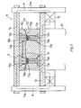
- Fig. 3
- is a vertical sectional view showing one preferable embodiment of a magnetic molding apparatus applied to the production method of the tone wheel of the present invention.
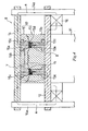
- Fig. 4
- shows another preferable embodiment of Fig. 3.
- Fig. 5
- is an enlarged view diagrammatically showing an essential part "X" in Fig. 3.
- Fig. 6
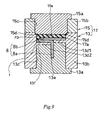
- is an enlarged view diagrammatically showing an essential part "Y" in Fig. 4.
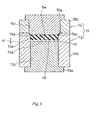
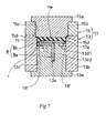
- Fig. 7
- shows a modified embodiment of Fig. 6.
- Fig. 8
- shows a modified embodiment of Fig. 6.
- Fig. 9
- shows a modified embodiment of Fig. 6.
- Fig. 10
- shows another preferable embodiment of Fig. 6.
- Fig. 11
- shows a modified embodiment of Fig. 10.
- Fig. 12
- shows a modified embodiment of Fig. 10.
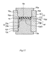
- Fig. 13
- shows a modified embodiment of Fig. 10.
- Fig. 14
- shows a modified embodiment of Fig. 10.
- Fig. 15
- shows a modified embodiment of Fig. 10.
- Fig. 16
- shows a modified embodiment of Fig. 10.
- Fig. 17
- shows a modified embodiment of Fig. 10.
- Now the preferred embodiments according to the present invention will be described referring to the attached drawings.
- Fig. 1 shows one supporting structure of the vehicle axis relative to a shaft 1 with a rolling
bearing unit 2. A tire wheel (not shown) is fixed to ahub wheel 3a constituting an inner wheel (rotary member) with abolt 3b. Thereference numeral 3c indicates a spline hole provided for thehub wheel 3a, the drive shaft 1 is fitted in thespline hole 3c to be integrally fixed with thehub wheel 3a and the rotary drive force of drive shaft 1 is transmitted to the tire wheel via thehub wheel 3a. Thereference numeral 3d indicates an inner wheel member and constitutes aninner wheel 3 together with thehub wheel 3a. - The reference numeral 4 indicates an outer wheel (fixed member) and is fixed to the vehicle suspension (not shown). Two rows of rolling elements (ball) 5... are interposed between the outer wheel 4 and the inner wheel 3 (
hub 3a andinner wheel member 3d) while being held with aretainer 5a. The reference numerals S, S' indicate a seal ring in order to prevent leakage of lubricant (such as grease) filled in a rolling portion of the rollingelements 5... or to prevent entering of muddy water and dirt from outside and the seal ring is provided under pressure between the outer wheel 4 and theinner wheel 3. - The seal ring S at the vehicle body side is constituted as a pack seal type seal ring as shown in the figure such that a ring like
core metal 6 to be fitted in the inner circumference of the outer wheel 4 under pressure, an elastic seal member (seal lip) 7 made of an elastic material like rubber to be fixed to thecore metal 6, and a slinger (core metal) 8 to be externally fitted in the outer circumference of theinner wheel member 3d are assembled. - The
slinger 8 comprises acylindrical portion 8a to be externally fitted in the outer circumference of theinner wheel member 3d and an outward brim portion (brim like portion) 8b of a part of thecylindrical portion 8a extending in the radial direction (centrifugal direction). - The
outward brim portion 8b is coupled in a centrifugal direction from one end of thecylindrical portion 8a and is folded back in the centripetal direction so as to be overlapped in the figure and a part thereof is designed to cohere to the end face of theinner wheel member 3d. Such a structure increases the sticking area of tone wheel 9, as mentioned later. - The
core metal 6 comprises acylindrical portion 6a to be internally fitted in the inner circumference of the outer wheel 4 and aninward brim portion 6b formed at the base of a rollingelement 5 side of thecylindrical portion 6a extending in the radial direction (centripetal direction). - The vehicle side surface (outer surface) of the
outward brim portion 3b of theslinger 8 is integrally attached with the tone wheel 9 which is a magnetic rubber sheet formed by mixing magnetic powder such as ferrite in a rubber material and is magnetized so as to alternately arrange a plurality of north poles and south poles in the circumferential direction. Amagnetic sensor 10 is fixed to the vehicle side (fixed member side) in such a manner that the detecting surface faces to the tone wheel 9 and constitutes a magnetic encoder E for detecting the rotary number (rotary speed) of vehicles together with the tone wheel 9. - At the seal ring S incorporated between the
inner wheel 3 and the outer wheel 4, theslinger 8 rotates around the axis of the drive shaft 1 according to the axial rotation of the drive shaft 1 and theinner wheel 3 and at the same time the tone wheel 9 rotates around the axis of the drive shaft 1, themagnetic sensor 10 detects the alternate magnetic change in the north pole and the south pole accompanied with the rotation of tone wheel 9, and the rotary speed and so on of the drive shaft 1, namely the tire wheel (not shown), are calculated by counting the pulse signals generated by the magnetic change. - The
core metal 6 or theslinger member 8 is formed by metal processing of the cold rolled steel sheet like SPCC into the shape as shown in the figure. The magnetic rubber sheet for the sealingmember 7 or the tone wheel 9 is formed such that a rubber material selected from NBR, H-NBR, ACM, AEM, FKM and so on is stuck to thecore metal 6 or theslinger 8 with an adhesive agent or at the same time of vulcanization molding to be integrated. As the rubber material for the latter, ferrite magnetic powder or rare earth magnetic powder is mixed in advance as mentioned above. - Next, a production method of tone wheel according to the present invention will be explained. Fig. 2 shows its diagrammatical procedures. At step S1, an unvulcanized rubber (elastic raw material) in which a fixed amount of anisotropic magnetic powder such as ferrite powder and additive are mixed with the above-mentioned unvulcanized rubber material in advance is charged in an annular cavity of the magnetic molding apparatus, which is mentioned later.
- Forming integrally with the core metal (slinger), the core metal is arranged in a fixed position in the cavity before charging the unvulcanized rubber. An adhesive agent is preferably applied in advance on the surface of the slinger to be attached with the tone wheel. At
step 2, while the magnetic field is acted on the charged unvulcanized rubber by applying the current to a coil for generating magnetic field as mentioned later, the rubber is heated (170 °C to 230 °C) and is further pressurized in case of pressure molding, thereby executing vulcanization magnetic molding. - The above-mentioned anisotropic magnetic powder mixed and blended in the unvulcanized rubber is aligned by the action of magnetic field at the vulcanization procedure such that the easy axis of magnetization becomes along the magnetic field direction, thereby being solidified in a vulcanized rubber layer as it is while being vulcanized.
- After completing the above magnetic molding and removal of dies at step S3, obtained are an annular vulcanized rubber molded body (annular molded body) or an integral molded body of the annular rubber layer (annular elastic material layer) with the core metal. At step 4, using the well-known magnetizing apparatus, the surface of the annular rubber layer of the molded body is magnetized with a pattern repeating a plurality of north poles and south poles in the circumferential direction, thereby completing the tone wheel 9 to comprise the above-mentioned encoder E.
- According to the tone wheel 9, under the magnetic molding procedure as mentioned above, the easy axis of magnetization of the contained anisotropic magnetic powder is arranged so as to be along the magnetic field direction, so that magnetizing can be accurately executed by the magnetizing procedure at the step 4 thereafter, thereby achieving very strong magnetic characteristics.
- Fig. 3 and Fig. 5 show one preferable embodiment of a magnetic molding apparatus applied to the production method of the tone wheel of the present invention. The magnetic molding apparatus A in the figure shows a pressure and hot molding apparatus, however it does not exclude an injection molding apparatus. In this embodiment, the elastic raw material is produced as an annular molded body which is separated from the core metal in case of magnetic molding procedure.
- In case of injection molding apparatus, an injection passage of an unvulcanized rubber communicated with the
cavity 17a is provided which starts at the center portion of the assembled molding die 17 as mentioned later. The magnetic molding apparatus A has amovable board 12 made of magnetic material which is moved up and down by aram 11; a fixedboard 14 made of magnetic material which is supported above themovable board 12 by means of asupport pillar 14a made of magnetic material; an upper metal mold (constituting one die block of assembled molding die) 15 attached to the lower surface of the fixedboard 14; a lower metal mold (constituting the other die block of assembled molding die) 13 disposed on themovable board 2; and acoil 16 for generating magnetic field attached to the lower surface of themovable board 12 concentrically with the ram 11 (concentric with anannular cavity 17a, mentioned later). - Further, heating means, a driving source for telescopic motion of
ram 11, and a driving means of thecoil 16 for generating magnetic field are provided therearound, although they are not shown in the figures. - The assembled molding die 17 comprises the
lower metal mold 13 and theupper metal mold 15, which are detachably engaged when themovable board 12 goes up accompanied with the extension ofram 11, thus molding theannular cavity 17a between themetal molds upper metal mold 15 forms anannular molding surface 15e at the tip of themagnetic die 15a and thelower metal mold 13 has an annular molding receivingsurface part 13d formed with anannular molding surface 13f on thenon-magnetic member 13b. - The
magnetic die member 13a is incorporated into the annular molding receivingsurface part 13d opposite to theannular molding surface 13f. Thelower metal mold 13 and theupper metal mold 15 are formed such thatmagnetic die members non-magnetic die members magnetic die member cavity 17a from up and down, and the non-magnetic molding dies 13b, 15b are processed to have such a shape to be disposed therearound. - The
magnetic die members cavity 17a respectively and function as a back yoke and a front yoke which constitute a apart of magnetic circuit at the time of generating a magnetic field. Themagnetic die member 13a and thenon-magnetic die member 13b, and themagnetic die member 15a and thenon-magnetic die member 15b are integrated by thermal insert respectively, and thereference numerals - The
magnetic die member 15a constituting theupper metal mold 15 faces the inside of thecavity 17a and is arranged so as to directly contact with an unvulcanized rubber (elastic raw material) r0 charged in thecavity 17a shown in the figure.Flash groove 15d connected to thematching surface 15c is formed at the circumference facing the inside of thecavity 17a. - The
non-magnetic die member 13b of thelower metal mold 13 faces the inside of thecavity 17a such that an annular molding receivingsurface part 13d covers the upper surface of themagnetic die member 13a and is interposed between the unvulcanized rubber material r0 charged in thecavity 17a and themagnetic die member 13a in such a manner that they do not contact with each other. - The unvulcanized rubber material r0 mixed with magnetic powder in advance is charged in the
cavity 17a, theram 11 is operated to go up themovable board 12, thereby executing hot and pressure molding while heating at the above-mentioned vulcanization temperature. At the same time of hot and pressure molding, the current is applied to thecoil 16 by means of a driving means, not shown, to run the current through a lead wire, thereby generating the magnetic field around thecoil 16 as shown with a line of magnetic force "a" in Fig. 3 - The line of magnetic force "a" forms a loop magnetic field of
support pillar 14a → fixedboard 14 →magnetic die member 15a of theupper metal mold 15 → unvulcanized rubber material r0 incavity 17a →part 13d ofnon-magnetic die member 13b oflower metal mold 13 →magnetic die member 13a oflower metal mold 13 →movable board 12 →coil 16. - The magnetic field is acted on the unvulcanized rubber r0 in the
cavity 17a in the direction of its thickness by the loop magnetic field, the anisotropic magnetic powder in the unvulcanized rubber material r0 with fluidity is aligned such that the easy axis of magnetization becomes along the magnetic field (magnetic line of force "a") by the act of magnetic field, thereby being solidified under such aligned condition while vulcanization is processing. - The
magnetic die members non-magnetic die members non-magnetic part 13d exists between the unvulcanized rubber material r0 in thecavity 17a and themagnetic die member 13a of thelower metal mold 13, thepart 13d slightly hinders the magnetic line of force "a" from passing, however, there is no problem to mold the magnetic field if the thickness "d" is set from 0.3 mm to 10 mm. - The unvulcanized rubber material r0 is designed not to directly contact with the
magnetic die member 13a of thelower metal mold 13 by providing thepart 13d, so that even if there may cause a little gap on the matching surfaces 13c of thelower metal mold 13 when being used several times, the unvulcanized rubber material r0 does not enter the gap and there is no fear of producing incursion flash. - Further, the matching
surface 13c of theupper metal mold 15 is formed so as to be connected with theflash groove 15d, so if there causes a little gap on thematching surface 15c as mentioned above, the flash formed by entering into the gap is removed as design flash together with the flash formed by theflash groove 15d. Therefore, there is no adverse effect on the quality like the prior molding method. - Fig. 4 and Fig. 6 show another preferable embodiment of a magnetic molding apparatus applied to the present invention. In this embodiment, the elastic raw material is united with a core metal to be produced as an annular molded body with core metal in the magnetic molding procedure. According to the magnetic molding apparatus B in this embodiment, the
slinger 8 as shown in Fig. 1 and the rubber material constituting the tone wheel 9 are attached to be integrally molded, acylindrical groove 13e, which communicates with thecavity 17a and is concentric with thecavity 17a, is formed on themagnetic die member 13a of thelower metal mold 13. - The substantially
cylindrical groove 13e is formed capable of being inserted with acylindrical portion 8a of theslinger 8 from thecavity 17a, when thecylindrical portion 8a is inserted into thecylindrical groove 13e, theslinger 8 is positioned at the bottom of thecavity 17a with thebrim portion 8b. - The
lower metal mold 13 is provided with annular molding wraparound receiving surface parts (projected portion of non-magnetic die member) 13d1, 13d2 formed with annularmolding wraparound surfaces non-magnetic member 13b and the annularmolding wraparound surfaces brim portion 8b of thecore metal 8 in thecavity 17a. - The upper surface of the
magnetic die member 13a facing thecavity 17a is covered with projected portions (a part of non-magnetic die member) 13d1, 13d2 projected into the width direction of thecavity 17a from both faces of thenon-magnetic die member 13b, whereby thebrim portion 8b of theslinger 8 and the projected portions 13d1, 13d2 exist between the unvulcanized rubber material r0 charged in thecavity 17a and themagnetic die member 13a so as not to directly contact the unvulcanized rubber material r0 and themagnetic die member 13a. - The lower face of the
magnetic die member 15a of theupper metal mold 15 faces thecavity 17a as mentioned above so as to directly contact with the unvulcanized rubber material r0 charged in thecavity 17a and theflash groove 15d is also formed. Thecavity 17a in this embodiment is formed such that the unvulcanized rubber material r0 wraps around both inner and outer circumferences of thebrim portion 8b of theslinger 8 to form the wraparound portion r. For this purpose, the wraparound receiving portions 13d1, 13d2 are also projected to receive the wraparound unvulcanized rubber material r0 as mentioned above. - If the unvulcanized rubber material r0 is entered, there is no fear of forming incursion flash caused when the unvulcanized rubber material r0 enters into the matching
surface 13c of the distal of themagnetic die member 13a and that of thenon-magnetic die member 13b because of the projected portions 13d1, 13d2 between themagnetic die member 13a and the unvulcanized rubber material r0 charged in thecavity 17a. Other structures are the same as the embodiment shown in Fig. 3 and Fig. 5 and the procedure of magnetic molding is the same as the embodiment, so the same reference numbers are allotted to the same members and their explanations are omitted here. - Fig. 7 to Fig. 9 show a modified embodiment when the
slinger 8 and a rubber material are integrally formed respectively, as mentioned above. In the embodiment in Fig. 7 the shape ofcavity 17a, namely the shape of molded body, is the same as that in Fig. 6, however, the projected portions 13d1, 13d2 have the different width. - Other structures are the same as those in Fig. 6. In the embodiments in Fig. 8, Fig. 9, the shape of the wraparound portion r of the unvulcanized rubber material r0 into the inner and outer circumferences of the
brim portion 8b in thecavity 17a is different and the projected portions 13d1, 13d2 are formed correspondingly. - The basic structure is the same as the above-mentioned embodiment even though there is difference in shape, so that the same operation and effect can be obtained in the case of magnetic molding. Therefore, these are optionally selected and applied as design matters. The other structure is the same as in the above-mentioned embodiment so the same reference numbers are allotted to the same members and their explanations are omitted here.
- Fig. 10 shows another embodiment of Fig. 6 and Fig. 11 to Fig. 17 show its modified embodiments. The
slinger 8 is comprised of acylindrical portion 8a and aninward brim portion 8c connected with the end of thecylindrical portion 8a. Theslinger 8 in Fig. 6 has a substantially T-shaped section, however, it is L-shaped in this embodiment. - A
cylindrical groove 13f to be inserted with thecylindrical portion 8a is formed on theouter matching surface 13c of themagnetic die member 13a and thenon-magnetic die member 13b and the projected portion (annular molding wraparound receiving surface part of a non-magnetic die member) 13d3, which covers the upper face of themagnetic die member 13a and extends to the inside of thecylindrical portion 8a, is projected out of the innernon-magnetic die member 13b. The function of projected portion 13d3 is the same as mentioned above, so that the operation and effect are also the same in case of magnetic molding. - The embodiments shown in Fig. 11 and Fig. 12 are different from the embodiment in Fig. 10 in that the wraparound portion r of the unvulcanized rubber material r0 into the inner circumference of the
brim portion 8c in thecavity 17a is modified and the projected portion 13d3 is correspondingly molded. In the embodiment shown in Fig. 13, the base portion of the projected portion 13d3 is tapered to be thick according to the wraparound portion r of the unvulcanized rubber material r0 into the inner circumference of thebrim portion 8c. - Further Fig. 14 to Fig. 17 show embodiments in which the width of projected portion 13d3 is made smaller and they show the shape of
cavity 17a, namely several shapes of the projected portion 13d3 corresponding to the wraparound portion r of the unvulcanized rubber material r0 into the inner circumference of thebrim portion 8c. - In these embodiments, the function of projected portion 13d3 is the same as the above-mentioned embodiments, so that the operation and effect are the same in case of magnetic molding and they are optionally selected and applied as design matters. The other structure is the same as the above-mentioned embodiment so the same reference numbers are allotted to the same members and their explanations are omitted here.
- In the embodiments shown in Fig. 10 to Fig. 17, the
brim portion 8c of theslinger 8 is formed inwardly, however it may be formed outwardly. The tone wheel 9 obtained by the method of the present invention is incorporated in the seal ring S of pack seal type, however the present invention is not limited to the embodiment. Further, in the embodiment in Fig. 1, the inner wheel is designed to be rotated, however, the tone wheel 9 of the present invention can be applied to the case where the outer wheel is rotated. In addition, an elastic material constituting the tone wheel 9 is made of rubber in the above-mentioned embodiments, however, it may be elastic resin material. - It is should be also noted that although the present invention proposes an assembled die which constitutes one die blocks and the other die blocks, such die blocks can be composed of several parts depending on their cavity shapes with flash grooves where elastic raw material is molded as annular molded bodies or annular molded bodies with slinger members. For example, such assembled die as shown in Fig. 10 can be divided into plural piece blocks in one type of die blocks and another type of die blocks.
The preferred embodiments described wherein are therefore only illustrative and by no means restrictive, the scope of the invention being indicated by the appended claims and all variations coming within the meaning of the claims are intended to be embraced therein.
Claims (5)
- A production method of a tone wheel (9) made of elastic material to be fixed to a rotating member, in which a magnetic encoder is assembled in combination with the tone wheel (9) and a magnetic sensor provided at a fixed member, the method comprising the following steps:- charging an elastic raw material (r0) mixed with a magnetic powder into an annular cavity (17a) of an assembled molding die (17), the assembled molding die (17) comprising a non-magnetic die member (13a, 15a) and a magnetic die member (13b, 15b) which constitutes a magnetic path;- generating a magnetic field in one predetermined direction and molding an annular molded body out of the elastic raw material (r0) mixed with the magnetic powder, with the assembled molding die (17) in the field, in which the magnetic field is applied to the elastic raw material (r0) in the annular cavity (17a) via the magnetic die member (13b, 15b), thereby aligning the magnetic powder in the elastic raw material (r0) in one direction corresponding to the magnetic field; and- magnetizing the surface of the annular molded body thus produced, with a magnetizing apparatus (16) in such a pattern that N poles and S poles are alternately arranged in its circumference;- wherein the assembled molding die (17) has one type of die blocks (15) and another type of die blocks (13) which are detachably engaged with each other, and has a flash groove (15d) at a matching surface where the distal sides of the one die blocks (15) and that of the other die blocks (13) are matched; and- wherein the one die blocks (15) have an annular molding surface formed on the magnetic die member side of the die (17), and the other die blocks (13) have an annular molding receiving surface part which is formed with an annular molding surface.
- A production method of a tone wheel (9) made of elastic material to be fixedly attached to a brim portion (8b) of a slinger member (8) fixed to a rotating member in which a magnetic encoder is assembled in combination with the tone wheel (9) and a magnetic sensor provided at a fixed member, and the slinger member (8) having a cylindrical body with the brim portion (8b), the method comprising the following steps:- charging an elastic raw material (r0) mixed with a magnetic powder together with the slinger member (8) into an annular cavity (17a) of an assembled molding die (17), the assembled molding die (17) comprising a non-magnetic die member (13a, 15a) and a magnetic die member (13b, 15b) which constitutes the magnetic path;- generating a magnetic field in one predetermined direction and molding an annular molded body with the slinger member (8) out of the elastic raw material (r0) mixed with the magnetic powder attached on the slinger member (8) with the assembled molding die (17) in the field, in which the magnetic field is applied to the elastic raw material (r0) in the annular cavity (17a) via the magnetic die member (13b, 15b), thereby aligning the magnetic powder in the elastic raw material (r0) in one direction corresponding to the magnetic field; and- magnetizing the surface of the annular molded body with the slinger member (8) thus produced, with a magnetizing apparatus (16) in such a pattern that N poles and S poles are alternately arranged in its circumference;- wherein the assembled molding die (17) has one type of die blocks (15) and another type of die blocks (13) which are detachably engaged with each other, and has a flash groove (15d) at a matching surface where the distal sides of the one die blocks (15) and that of the other die blocks (13) are matched; and- wherein the one die blocks (15) have an annular molding surface formed on the magnetic die member side of the die (17), and the other die blocks (13) have an annular molding wraparound receiving surface part (13d1, 13d2) formed with a partial annular molding receiving surface for receiving the wraparound part (13f) of the elastic raw material which partially covers the reverse side of the brim of the slinger member (8) in the cavity (17a) on the non-magnetic die member side of the die (17).
- The production method as set forth in claim 1 or 2,
wherein the elastic raw material (r0) is an unvulcanized rubber material and heated and vulcanized in the molding step. - A production method as set forth in claim 1 or 2,
wherein the magnetic powder is an anisotropic ferrite powder. - The production method as set forth in claim 1 or 2,
wherein the annular molding receiving surface part or the partial annular molding receiving surface part of the non-magnetic die member has a thickness of 0.3 mm to 10 mm in the direction of the magnetic field as applied to the cavity (17a).
Applications Claiming Priority (1)
| Application Number | Priority Date | Filing Date | Title |
|---|---|---|---|
| JP2005188244A JP2007010343A (en) | 2005-06-28 | 2005-06-28 | Tone wheel manufacturing method |
Publications (1)
| Publication Number | Publication Date |
|---|---|
| EP1739435A2 true EP1739435A2 (en) | 2007-01-03 |
Family
ID=37055170
Family Applications (1)
| Application Number | Title | Priority Date | Filing Date |
|---|---|---|---|
| EP20060013396 Withdrawn EP1739435A2 (en) | 2005-06-28 | 2006-06-28 | Production method of tone wheel |
Country Status (3)
| Country | Link |
|---|---|
| US (1) | US7425295B2 (en) |
| EP (1) | EP1739435A2 (en) |
| JP (1) | JP2007010343A (en) |
Cited By (1)
| Publication number | Priority date | Publication date | Assignee | Title |
|---|---|---|---|---|
| CN104690882A (en) * | 2013-12-05 | 2015-06-10 | 中西金属工业株式会社 | Ring-shaped insert molded article |
Families Citing this family (19)
| Publication number | Priority date | Publication date | Assignee | Title |
|---|---|---|---|---|
| KR100750700B1 (en) * | 2005-05-30 | 2007-08-22 | 주식회사 유성에프티 | The manufacturing method and manufacturing apparatus of tone wheel for vehicle and the tone wheel for vehicle manufactured by method thereof |
| JP5089967B2 (en) * | 2006-12-01 | 2012-12-05 | Ntn株式会社 | Manufacturing method of magnetic encoder, magnetic field injection molding apparatus for multipolar magnet, and mold for multipolar magnet |
| JP2008258460A (en) * | 2007-04-06 | 2008-10-23 | Uchiyama Mfg Corp | Manufacturing method of annular resin magnet for magnetic encoder |
| JP2009097994A (en) * | 2007-10-17 | 2009-05-07 | Ntn Corp | Magnetic encoder and manufacturing method thereof, and rolling bearing |
| JP2009097993A (en) * | 2007-10-17 | 2009-05-07 | Ntn Corp | Magnetic encoder and manufacturing method thereof, and rolling bearing |
| JP2009097996A (en) * | 2007-10-17 | 2009-05-07 | Ntn Corp | Magnetic encoder and rolling bearing |
| JP2009145067A (en) * | 2007-12-11 | 2009-07-02 | Ntn Corp | Magnetic encoder manufacturing apparatus and magnetic encoder manufacturing method |
| JP2009097991A (en) * | 2007-10-17 | 2009-05-07 | Ntn Corp | Magnetic encoder and manufacturing method thereof, and rolling bearing |
| WO2009050968A1 (en) * | 2007-10-17 | 2009-04-23 | Ntn Corporation | Magnetic encoder, apparatus for producing magnetic encoder, process for producing magnetic encoder, and rolling bearing |
| JP2009097995A (en) * | 2007-10-17 | 2009-05-07 | Ntn Corp | Magnetic encoder and rolling bearing |
| JP5126776B2 (en) * | 2007-10-17 | 2013-01-23 | Ntn株式会社 | Manufacturing method of magnetic encoder |
| JP2009097992A (en) * | 2007-10-17 | 2009-05-07 | Ntn Corp | Magnetic encoder and manufacturing method thereof, and rolling bearing |
| JP2009097997A (en) * | 2007-10-17 | 2009-05-07 | Ntn Corp | Magnetic encoder and rolling bearing |
| JP5178259B2 (en) * | 2008-03-14 | 2013-04-10 | 株式会社ブリヂストン | Conveyor belt and method for manufacturing conveyor belt |
| JP6021050B2 (en) * | 2012-04-27 | 2016-11-02 | 内山工業株式会社 | Cover manufacturing method and press die used therefor |
| JP6536104B2 (en) * | 2014-06-05 | 2019-07-03 | 中西金属工業株式会社 | Method of manufacturing annular insert molded article |
| JP6424481B2 (en) * | 2014-06-11 | 2018-11-21 | 中西金属工業株式会社 | Magnetic encoder and method of manufacturing the same |
| JP6550219B2 (en) * | 2014-08-06 | 2019-07-24 | Ntn株式会社 | Wheel bearing device |
| JP6724533B2 (en) * | 2016-05-09 | 2020-07-15 | 中西金属工業株式会社 | Radial magnetic encoder, bearing device including radial magnetic encoder, and method for manufacturing radial magnetic encoder |
Family Cites Families (9)
| Publication number | Priority date | Publication date | Assignee | Title |
|---|---|---|---|---|
| JPS5948742B2 (en) * | 1982-03-05 | 1984-11-28 | 住友ベークライト株式会社 | Mold for magnetic field forming |
| JPH01275113A (en) * | 1988-04-28 | 1989-11-02 | Yazaki Corp | Manufacturing device for rotary plastic magnet |
| JP3564372B2 (en) * | 2000-09-04 | 2004-09-08 | 内山工業株式会社 | Manufacturing method of rubber encoder |
| JP2002131082A (en) * | 2000-10-24 | 2002-05-09 | Uchiyama Mfg Corp | Manufacturing method of magnetic encoder |
| JP3898972B2 (en) * | 2002-04-08 | 2007-03-28 | 内山工業株式会社 | Forming method of cylindrical encoder |
| JP2004053410A (en) * | 2002-07-19 | 2004-02-19 | Uchiyama Mfg Corp | Magnetic encoder |
| JP2004077318A (en) * | 2002-08-20 | 2004-03-11 | Uchiyama Mfg Corp | Magnetic encoder |
| US20040183702A1 (en) * | 2003-01-23 | 2004-09-23 | Daniel Nachtigal | Magnetizable thermoplastic elastomers |
| US20050007226A1 (en) * | 2003-05-22 | 2005-01-13 | Uchiyama Manufacturing Corp. | Magnetic encoder |
-
2005
- 2005-06-28 JP JP2005188244A patent/JP2007010343A/en not_active Withdrawn
-
2006
- 2006-06-28 US US11/476,085 patent/US7425295B2/en not_active Expired - Fee Related
- 2006-06-28 EP EP20060013396 patent/EP1739435A2/en not_active Withdrawn
Cited By (3)
| Publication number | Priority date | Publication date | Assignee | Title |
|---|---|---|---|---|
| CN104690882A (en) * | 2013-12-05 | 2015-06-10 | 中西金属工业株式会社 | Ring-shaped insert molded article |
| EP2881232A1 (en) * | 2013-12-05 | 2015-06-10 | Nakanishi Metal Works Co. Ltd. | Ring-shaped insert molded article |
| CN104690882B (en) * | 2013-12-05 | 2018-07-17 | 中西金属工业株式会社 | Ring-shaped insert-molded article |
Also Published As
| Publication number | Publication date |
|---|---|
| US20070007697A1 (en) | 2007-01-11 |
| US7425295B2 (en) | 2008-09-16 |
| JP2007010343A (en) | 2007-01-18 |
Similar Documents
| Publication | Publication Date | Title |
|---|---|---|
| EP1739435A2 (en) | Production method of tone wheel | |
| US8049645B2 (en) | Cylindrical cover-attached encoder apparatus | |
| EP3023746B1 (en) | Magnetic encoder device and rotation detection device | |
| KR101364677B1 (en) | Sealing device | |
| CN106030137B (en) | Roller bearing unit with rotary speed detecting device | |
| US20100061671A1 (en) | Wheel Bearing Apparatus Incorporated With A Wheel Speed Detecting Apparatus | |
| US20090219017A1 (en) | Tone Wheel and Method for Manufacturing The Same | |
| JP3257149B2 (en) | Wheel structure of annular magnet | |
| CN101939553A (en) | Wheel bearing unit with rotation detection device | |
| WO2015056526A1 (en) | Combination seal ring with encoder and roller bearing unit with encoder | |
| JP2013007575A (en) | Sensor apparatus | |
| EP2842651B1 (en) | Cover manufacturing method and press die used in same | |
| JP5609554B2 (en) | Magnetized pulsar ring, rolling bearing device, and method of manufacturing magnetized pulsar ring | |
| JP2005030547A (en) | Rolling bearing unit with rotational speed detector | |
| US20090039561A1 (en) | Production method of tone wheel | |
| JPH09133698A (en) | Rolling bearing unit with tone wheel | |
| JP2007192383A (en) | Fixed-side sealing member for sensor-equipped sealing device for rolling bearing device and method for manufacturing the same | |
| US20210003170A1 (en) | Magnetic impulse ring, bearing unit and rotary electrical machine comprising a magnetic impulse ring, and method to obtain a magnetic impulse ring | |
| JP4590273B2 (en) | Tone wheel | |
| US20060186577A1 (en) | Method of manufacturing cylindrical encoder | |
| JP6665511B2 (en) | Method of manufacturing protective cover having sensor holder, and method of manufacturing bearing device provided with the protective cover | |
| JP2008258460A (en) | Manufacturing method of annular resin magnet for magnetic encoder | |
| JP4925451B2 (en) | Magnetic encoder | |
| JPH09203415A (en) | Rolling bearing unit with tone wheel | |
| JP2009185920A (en) | Wheel bearing device with rotation detector |
Legal Events
| Date | Code | Title | Description |
|---|---|---|---|
| PUAI | Public reference made under article 153(3) epc to a published international application that has entered the european phase |
Free format text: ORIGINAL CODE: 0009012 |
|
| AK | Designated contracting states |
Kind code of ref document: A2 Designated state(s): AT BE BG CH CY CZ DE DK EE ES FI FR GB GR HU IE IS IT LI LT LU LV MC NL PL PT RO SE SI SK TR |
|
| AX | Request for extension of the european patent |
Extension state: AL BA HR MK YU |
|
| STAA | Information on the status of an ep patent application or granted ep patent |
Free format text: STATUS: THE APPLICATION HAS BEEN WITHDRAWN |
|
| 18W | Application withdrawn |
Effective date: 20100426 |