EP1739337B1 - Support stands for power plants - Google Patents
Support stands for power plants Download PDFInfo
- Publication number
- EP1739337B1 EP1739337B1 EP06251582A EP06251582A EP1739337B1 EP 1739337 B1 EP1739337 B1 EP 1739337B1 EP 06251582 A EP06251582 A EP 06251582A EP 06251582 A EP06251582 A EP 06251582A EP 1739337 B1 EP1739337 B1 EP 1739337B1
- Authority
- EP
- European Patent Office
- Prior art keywords
- stand
- enclosure
- pod
- socket
- stand according
- Prior art date
- Legal status (The legal status is an assumption and is not a legal conclusion. Google has not performed a legal analysis and makes no representation as to the accuracy of the status listed.)
- Active
Links
- 238000010248 power generation Methods 0.000 claims abstract description 5
- 239000002828 fuel tank Substances 0.000 claims description 3
- 239000000463 material Substances 0.000 claims description 3
- 239000002184 metal Substances 0.000 claims description 3
- 239000012530 fluid Substances 0.000 claims description 2
- 238000004519 manufacturing process Methods 0.000 claims 1
- 238000002485 combustion reaction Methods 0.000 description 2
- 238000006243 chemical reaction Methods 0.000 description 1
- 239000000446 fuel Substances 0.000 description 1
- 239000007789 gas Substances 0.000 description 1
- 230000030279 gene silencing Effects 0.000 description 1
- 239000003921 oil Substances 0.000 description 1
- XLYOFNOQVPJJNP-UHFFFAOYSA-N water Substances O XLYOFNOQVPJJNP-UHFFFAOYSA-N 0.000 description 1
Images


Classifications
-
- F—MECHANICAL ENGINEERING; LIGHTING; HEATING; WEAPONS; BLASTING
- F16—ENGINEERING ELEMENTS AND UNITS; GENERAL MEASURES FOR PRODUCING AND MAINTAINING EFFECTIVE FUNCTIONING OF MACHINES OR INSTALLATIONS; THERMAL INSULATION IN GENERAL
- F16M—FRAMES, CASINGS OR BEDS OF ENGINES, MACHINES OR APPARATUS, NOT SPECIFIC TO ENGINES, MACHINES OR APPARATUS PROVIDED FOR ELSEWHERE; STANDS; SUPPORTS
- F16M3/00—Portable or wheeled frames or beds, e.g. for emergency power-supply aggregates, compressor sets
-
- F—MECHANICAL ENGINEERING; LIGHTING; HEATING; WEAPONS; BLASTING
- F16—ENGINEERING ELEMENTS AND UNITS; GENERAL MEASURES FOR PRODUCING AND MAINTAINING EFFECTIVE FUNCTIONING OF MACHINES OR INSTALLATIONS; THERMAL INSULATION IN GENERAL
- F16M—FRAMES, CASINGS OR BEDS OF ENGINES, MACHINES OR APPARATUS, NOT SPECIFIC TO ENGINES, MACHINES OR APPARATUS PROVIDED FOR ELSEWHERE; STANDS; SUPPORTS
- F16M5/00—Engine beds, i.e. means for supporting engines or machines on foundations
Definitions
- This invention relates to support stands for power plant systems and in particular to support stands for internal combustion engine driven electrical power generators.
- the invention finds particular usefulness in the field of hiring, renting and leasing of such power plant systems.
- Power plant systems or generators may be provided within a rigid housing, usually with sockets provided on the outside thereof for power supply connection. There ' is a need to place such power plant systems in locations where there is a risk of accidental damage to the housing due to collisions caused by other objects such as, for example, vehicles, lorries, fork lift trucks, cars, cranes and the like accidentally colliding with the power plant. There is also a need to be able to transport such power plant systems to and from hire sites and distribution or sales centres.
- JP 10196392 shows an engine generator with an exhaust cover projecting from the housing to enhance silencing.
- US 3815965 discloses a housing for an air compressor with tool box compartments at the sides and ends to dissipate sound.
- An object of the present invention is to provide a support stand which provides protection for the power plant system when the plant is in or being moved to an operable position, and which can be easily repaired in the event of accidental damage.
- a support stand for an electrical power generation plant having an enclosure, the stand comprising a stand base for supporting the plant enclosure, and a detachable pod mounted to the base and arranged to project beyond an edge of the enclosure to provide a structure for protecting the enclosure from damage due to collisions by other objects.
- the plant collide with another object, it will be protected by the pod. Should the pod become damaged, it can be removed and replaced. Furthermore, a stand may easily be adapted for the rental market by adding the pods.
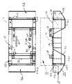
- a stand 8 also known as a skid, for an internal combustion engine driven electrical power generator plant having an enclosure 11 (shown dotted in Figure 1 ).
- the stand has a base 10 incorporating a fuel tank 12 (shown dotted) and internal bulkheads 13 that define a bund 14 that has an internal volume to accommodate and contain within the bund 14 any leakages of fluids (eg. oil, water, fuel).
- the stand base 10 has a profile in plan ("foot-print") corresponding to the profile in plan of the power generator plant enclosure 11.
- the top plate 15 of the stand has openings 17, fixing brackets 18, cut outs (not shown) and pipe connections 20 to accommodate features on the underside of the generator plant.
- the stand base 10 includes two sheet metal fabricated feet 21 welded to the top plate 15 and side of the stand 10 adjacent each end edge of the tank 12.
- the stand 10 incorporates two pods 22, 23 or skid ends constructed in accordance with the present invention.
- Each pod 22, 23 is made of a sheet metal fabricated hollow member that is releasably bolted at locations to the end edges of the stand base 10.
- each pod 22, 23 comprises a sheet of material bent around parallel axes to form a top surface 26, an end surface 28, and a lower surface 30 together forming the projecting part of the pod 22, 23; and an underneath surface 32 and inside surface 34 together fitting around the foot 21, and having holes 36 for attaching to the foot 21.
- the pod 22, 23 also has a pair of apertured flanges 38 extending downwardly from the top surface 26 for attachment to the edge of the base 10.
- the pods 22, 23 have a profile when viewed from the side, that projects beyond the ends of the stand base 10 to provide a crumple zone or protection zone.
- the pods 22, 23 are designed to prevent collisions by vehicles and other objects damaging the stand 10, the fuel tank 12, the bund 14 and the generator plant enclosure 11.
- the pods 22, 23 also enables hot or dangerous items such as hot exhaust pipes (not shown) to be re-routed to discharge into the interior of one or more of the pods, and therefore protect persons from injuring themselves. Since the pods 22, 23 are open at their ends exhaust gases are free to vent from the pod or pods.
- hot exhaust pipes not shown
- the pods are basically an 'easy to bolt-on' extra that enables the rental sector of the market to transport the power plant together with the stand base 10 assembled together from place to place to position the power plant at operational sites. Since the "foot-print" area in plan view of the power plant enclosure 11 and stand base 10 is smaller than would be the case with the pods 22, 23 in place, the power plant takes up less space during transporting the power plant from place to place.
- a detachable cover 40 may also be supplied for attaching to the enclosure 11 adjacent the power plant sockets 42.
- the cover 40 projects beyond the sockets to protect them from damage.
Abstract
Description
- This invention relates to support stands for power plant systems and in particular to support stands for internal combustion engine driven electrical power generators. The invention finds particular usefulness in the field of hiring, renting and leasing of such power plant systems.
- Power plant systems or generators may be provided within a rigid housing, usually with sockets provided on the outside thereof for power supply connection. There ' is a need to place such power plant systems in locations where there is a risk of accidental damage to the housing due to collisions caused by other objects such as, for example, vehicles, lorries, fork lift trucks, cars, cranes and the like accidentally colliding with the power plant. There is also a need to be able to transport such power plant systems to and from hire sites and distribution or sales centres.
-
JP 10196392 US 3815965 discloses a housing for an air compressor with tool box compartments at the sides and ends to dissipate sound. - An object of the present invention is to provide a support stand which provides protection for the power plant system when the plant is in or being moved to an operable position, and which can be easily repaired in the event of accidental damage.
- According to one aspect of the present invention there is provided a support stand for an electrical power generation plant having an enclosure, the stand comprising a stand base for supporting the plant enclosure, and a detachable pod mounted to the base and arranged to project beyond an edge of the enclosure to provide a structure for protecting the enclosure from damage due to collisions by other objects.
- Thus, should the plant collide with another object, it will be protected by the pod. Should the pod become damaged, it can be removed and replaced. Furthermore, a stand may easily be adapted for the rental market by adding the pods.
- The present invention will now be described, by way of example with reference to the accompanying drawings in which:-
-
Figure 1 is a side elevation of a support stand for a power plant having pods constructed in accordance with one embodiment of the present invention. -
Figure 2 is a plan view of the stand shown inFigure 1 ; -
Figure 3 is an end view of the stand ofFigure 1 ; -
Figure 4 is a perspective view of the stand ofFigure 1 ; -
Figure 5 is a perspective view of a detachable pod of the stand ofFigure 1 ; -
Figure 6 is a side view of the pod ofFigure 5 ; and -
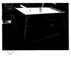
Figure 7 is a perspective view of a power generator plant enclosure mounted on the support stand ofFigure 1 . - Referring to
Figures 1 and7 there is shown astand 8, also known as a skid, for an internal combustion engine driven electrical power generator plant having an enclosure 11 (shown dotted inFigure 1 ). The stand has abase 10 incorporating a fuel tank 12 (shown dotted) andinternal bulkheads 13 that define abund 14 that has an internal volume to accommodate and contain within thebund 14 any leakages of fluids (eg. oil, water, fuel). Thestand base 10 has a profile in plan ("foot-print") corresponding to the profile in plan of the powergenerator plant enclosure 11. Thetop plate 15 of the stand hasopenings 17,fixing brackets 18, cut outs (not shown) andpipe connections 20 to accommodate features on the underside of the generator plant. Thestand base 10 includes two sheet metal fabricatedfeet 21 welded to thetop plate 15 and side of thestand 10 adjacent each end edge of thetank 12. - The
stand 10 incorporates twopods pod stand base 10. For example, eachpod top surface 26, anend surface 28, and alower surface 30 together forming the projecting part of thepod underneath surface 32 and insidesurface 34 together fitting around thefoot 21, and havingholes 36 for attaching to thefoot 21. Thepod apertured flanges 38 extending downwardly from thetop surface 26 for attachment to the edge of thebase 10. - The
pods stand base 10 to provide a crumple zone or protection zone. Thepods stand 10, thefuel tank 12, thebund 14 and thegenerator plant enclosure 11. - The
pods pods - The pods are basically an 'easy to bolt-on' extra that enables the rental sector of the market to transport the power plant together with the
stand base 10 assembled together from place to place to position the power plant at operational sites. Since the "foot-print" area in plan view of thepower plant enclosure 11 andstand base 10 is smaller than would be the case with thepods - A detachable cover 40 may also be supplied for attaching to the
enclosure 11 adjacent the power plant sockets 42. The cover 40 projects beyond the sockets to protect them from damage. - This also enables distributors the flexibility of stocking "standard" power plants that do not have
pods pods
Claims (11)
- A support stand (8) for an electrical power generation plant having an enclosure (11), the stand comprising a stand base (10) for supporting the plant enclosure, and a detachable pod (22, 23) mounted to the base and arranged to project beyond an edge of the enclosure to provide a structure for protecting the enclosure from damage due to collisions by other objects.
- A stand according to claim 1 wherein the or each pod is fabricated from sheet material to define a hollow structure.
- A stand according to claim 1 or claim 2 comprising a pair of pods provided at opposite edges of the stand.
- A stand according to any one of the preceding claims wherein the stand comprises a fuel tank (12) within an outer structure made of a sheet material fabrication.
- A stand according to claim 4 wherein the stand includes a bund (14) having an interior volume sufficient to contain fluid spillages.
- A stand according to claim 3 wherein the stand includes a foot (21) adjacent each opposite edge of the stand.
- A stand according to claim 6, in which the or each pod is attached to a foot of the stand.
- A stand according to any one of any preceding claim wherein the structure is made by folding a sheet metal about two or more axes.
- A stand according to any preceding claim, in which the or each pod extends substantially along the length of an edge of the stand.
- An electrical power generation plant having a stand as claimed in any preceding claim.
- An electrical power generation plant as claimed in claim 10, having an enclosure and at least one socket (42) projecting from the enclosure, and comprising a detachable socket (40) cover provided on the enclosure adjacent the socket(s) and projecting beyond the socket(s) for protecting the socket(s) from damage.
Applications Claiming Priority (1)
| Application Number | Priority Date | Filing Date | Title |
|---|---|---|---|
| GBGB0506803.6A GB0506803D0 (en) | 2005-04-04 | 2005-04-04 | Support stands for power plants |
Publications (3)
| Publication Number | Publication Date |
|---|---|
| EP1739337A2 EP1739337A2 (en) | 2007-01-03 |
| EP1739337A3 EP1739337A3 (en) | 2007-03-07 |
| EP1739337B1 true EP1739337B1 (en) | 2008-08-27 |
Family
ID=34586668
Family Applications (1)
| Application Number | Title | Priority Date | Filing Date |
|---|---|---|---|
| EP06251582A Active EP1739337B1 (en) | 2005-04-04 | 2006-03-23 | Support stands for power plants |
Country Status (5)
| Country | Link |
|---|---|
| EP (1) | EP1739337B1 (en) |
| AT (1) | ATE406541T1 (en) |
| DE (1) | DE602006002433D1 (en) |
| ES (1) | ES2316020T3 (en) |
| GB (1) | GB0506803D0 (en) |
Families Citing this family (1)
| Publication number | Priority date | Publication date | Assignee | Title |
|---|---|---|---|---|
| EA033262B1 (en) * | 2014-07-25 | 2019-09-30 | Эс.Пи.Эм. ФЛОУ КОНТРОЛ, ИНК. | System and method for reinforcing recirocating pump |
Family Cites Families (5)
| Publication number | Priority date | Publication date | Assignee | Title |
|---|---|---|---|---|
| FR1574912A (en) * | 1968-06-05 | 1969-07-18 | ||
| US3815965A (en) * | 1972-10-10 | 1974-06-11 | Smith & Co Inc Gordon | Air compressor housings |
| JPH10196392A (en) * | 1997-01-10 | 1998-07-28 | Yamaha Motor Co Ltd | Exhaust structure of engine generator |
| US6520124B2 (en) * | 2000-12-13 | 2003-02-18 | Tramont Corporation | Double walled fuel tank with integral generator set mounting frame |
| JP4167561B2 (en) * | 2003-07-10 | 2008-10-15 | 本田技研工業株式会社 | Engine driven work machine |
-
2005
- 2005-04-04 GB GBGB0506803.6A patent/GB0506803D0/en not_active Ceased
-
2006
- 2006-03-23 AT AT06251582T patent/ATE406541T1/en not_active IP Right Cessation
- 2006-03-23 ES ES06251582T patent/ES2316020T3/en active Active
- 2006-03-23 EP EP06251582A patent/EP1739337B1/en active Active
- 2006-03-23 DE DE602006002433T patent/DE602006002433D1/en active Active
Also Published As
| Publication number | Publication date |
|---|---|
| ES2316020T3 (en) | 2009-04-01 |
| ATE406541T1 (en) | 2008-09-15 |
| DE602006002433D1 (en) | 2008-10-09 |
| GB0506803D0 (en) | 2005-05-11 |
| EP1739337A2 (en) | 2007-01-03 |
| EP1739337A3 (en) | 2007-03-07 |
Similar Documents
| Publication | Publication Date | Title |
|---|---|---|
| US8587136B2 (en) | Mobile power system | |
| EP2411300B1 (en) | Packing method and packing system for three aerogenerator blades | |
| CN104864226B (en) | Power station and assembly for transporting combustion engines and method of construction thereof | |
| US8207621B2 (en) | Modular panels for enclosures | |
| US20110204013A1 (en) | Welding Power Supply External Protective Support Structure | |
| JPWO2016027377A1 (en) | Automotive battery pack | |
| US8235009B2 (en) | Energy generating modules with exterior wall fuel chambers | |
| EP1739337B1 (en) | Support stands for power plants | |
| US7717662B2 (en) | Utility truck combined with hoist, lift or crane elements | |
| US9102347B2 (en) | System and method for modular transportation of a welding system | |
| US6103995A (en) | Mounting bracket for engine-driven welder | |
| US9010832B2 (en) | Multi-piece vehicle tank enclosure | |
| US11648990B2 (en) | Configurable common deck system | |
| US9551451B2 (en) | Skid structure for a powertrain | |
| JP5753428B2 (en) | Engine working machine | |
| CN214931912U (en) | Automobile rear axle transfer device | |
| JP4624073B2 (en) | Air conditioning equipment, installation method of external air conditioner, and manufacturing method of air conditioning equipment | |
| US9839154B2 (en) | Flat roof inverter rack | |
| JP2014051166A (en) | Emergency outrigger | |
| JP2018523773A (en) | Wind turbine tower cooling panel assembly and wind turbine tower | |
| US10573863B2 (en) | Battery and auxiliary power unit mounting system | |
| US6254047B1 (en) | Equipment roller/slide support | |
| CN214693144U (en) | Electric fork-lift truck automobile body with guard plate | |
| CN220474440U (en) | Radiator protector | |
| EP2246229B1 (en) | Integration system of test ports and/or compressed air filling ports in vehicle accessories, especially of industrial or commercial vehicles |
Legal Events
| Date | Code | Title | Description |
|---|---|---|---|
| PUAI | Public reference made under article 153(3) epc to a published international application that has entered the european phase |
Free format text: ORIGINAL CODE: 0009012 |
|
| AK | Designated contracting states |
Kind code of ref document: A2 Designated state(s): AT BE BG CH CY CZ DE DK EE ES FI FR GB GR HU IE IS IT LI LT LU LV MC NL PL PT RO SE SI SK TR |
|
| AX | Request for extension of the european patent |
Extension state: AL BA HR MK YU |
|
| PUAL | Search report despatched |
Free format text: ORIGINAL CODE: 0009013 |
|
| AK | Designated contracting states |
Kind code of ref document: A3 Designated state(s): AT BE BG CH CY CZ DE DK EE ES FI FR GB GR HU IE IS IT LI LT LU LV MC NL PL PT RO SE SI SK TR |
|
| AX | Request for extension of the european patent |
Extension state: AL BA HR MK YU |
|
| 17P | Request for examination filed |
Effective date: 20070906 |
|
| 17Q | First examination report despatched |
Effective date: 20071010 |
|
| AKX | Designation fees paid |
Designated state(s): AT BE BG CH CY CZ DE DK EE ES FI FR GB GR HU IE IS IT LI LT LU LV MC NL PL PT RO SE SI SK TR |
|
| GRAP | Despatch of communication of intention to grant a patent |
Free format text: ORIGINAL CODE: EPIDOSNIGR1 |
|
| GRAS | Grant fee paid |
Free format text: ORIGINAL CODE: EPIDOSNIGR3 |
|
| GRAA | (expected) grant |
Free format text: ORIGINAL CODE: 0009210 |
|
| AK | Designated contracting states |
Kind code of ref document: B1 Designated state(s): AT BE BG CH CY CZ DE DK EE ES FI FR GB GR HU IE IS IT LI LT LU LV MC NL PL PT RO SE SI SK TR |
|
| REG | Reference to a national code |
Ref country code: GB Ref legal event code: FG4D |
|
| REG | Reference to a national code |
Ref country code: CH Ref legal event code: EP |
|
| REG | Reference to a national code |
Ref country code: IE Ref legal event code: FG4D |
|
| REF | Corresponds to: |
Ref document number: 602006002433 Country of ref document: DE Date of ref document: 20081009 Kind code of ref document: P |
|
| REG | Reference to a national code |
Ref country code: SE Ref legal event code: TRGR |
|
| PG25 | Lapsed in a contracting state [announced via postgrant information from national office to epo] |
Ref country code: IS Free format text: LAPSE BECAUSE OF FAILURE TO SUBMIT A TRANSLATION OF THE DESCRIPTION OR TO PAY THE FEE WITHIN THE PRESCRIBED TIME-LIMIT Effective date: 20081227 Ref country code: LT Free format text: LAPSE BECAUSE OF FAILURE TO SUBMIT A TRANSLATION OF THE DESCRIPTION OR TO PAY THE FEE WITHIN THE PRESCRIBED TIME-LIMIT Effective date: 20080827 |
|
| PG25 | Lapsed in a contracting state [announced via postgrant information from national office to epo] |
Ref country code: SI Free format text: LAPSE BECAUSE OF FAILURE TO SUBMIT A TRANSLATION OF THE DESCRIPTION OR TO PAY THE FEE WITHIN THE PRESCRIBED TIME-LIMIT Effective date: 20080827 Ref country code: LV Free format text: LAPSE BECAUSE OF FAILURE TO SUBMIT A TRANSLATION OF THE DESCRIPTION OR TO PAY THE FEE WITHIN THE PRESCRIBED TIME-LIMIT Effective date: 20080827 Ref country code: FI Free format text: LAPSE BECAUSE OF FAILURE TO SUBMIT A TRANSLATION OF THE DESCRIPTION OR TO PAY THE FEE WITHIN THE PRESCRIBED TIME-LIMIT Effective date: 20080827 Ref country code: AT Free format text: LAPSE BECAUSE OF FAILURE TO SUBMIT A TRANSLATION OF THE DESCRIPTION OR TO PAY THE FEE WITHIN THE PRESCRIBED TIME-LIMIT Effective date: 20080827 |
|
| PG25 | Lapsed in a contracting state [announced via postgrant information from national office to epo] |
Ref country code: BE Free format text: LAPSE BECAUSE OF FAILURE TO SUBMIT A TRANSLATION OF THE DESCRIPTION OR TO PAY THE FEE WITHIN THE PRESCRIBED TIME-LIMIT Effective date: 20080827 |
|
| REG | Reference to a national code |
Ref country code: ES Ref legal event code: FG2A Ref document number: 2316020 Country of ref document: ES Kind code of ref document: T3 |
|
| PG25 | Lapsed in a contracting state [announced via postgrant information from national office to epo] |
Ref country code: BG Free format text: LAPSE BECAUSE OF FAILURE TO SUBMIT A TRANSLATION OF THE DESCRIPTION OR TO PAY THE FEE WITHIN THE PRESCRIBED TIME-LIMIT Effective date: 20081127 Ref country code: DK Free format text: LAPSE BECAUSE OF FAILURE TO SUBMIT A TRANSLATION OF THE DESCRIPTION OR TO PAY THE FEE WITHIN THE PRESCRIBED TIME-LIMIT Effective date: 20080827 |
|
| PG25 | Lapsed in a contracting state [announced via postgrant information from national office to epo] |
Ref country code: PT Free format text: LAPSE BECAUSE OF FAILURE TO SUBMIT A TRANSLATION OF THE DESCRIPTION OR TO PAY THE FEE WITHIN THE PRESCRIBED TIME-LIMIT Effective date: 20090127 Ref country code: CZ Free format text: LAPSE BECAUSE OF FAILURE TO SUBMIT A TRANSLATION OF THE DESCRIPTION OR TO PAY THE FEE WITHIN THE PRESCRIBED TIME-LIMIT Effective date: 20080827 Ref country code: SK Free format text: LAPSE BECAUSE OF FAILURE TO SUBMIT A TRANSLATION OF THE DESCRIPTION OR TO PAY THE FEE WITHIN THE PRESCRIBED TIME-LIMIT Effective date: 20080827 Ref country code: RO Free format text: LAPSE BECAUSE OF FAILURE TO SUBMIT A TRANSLATION OF THE DESCRIPTION OR TO PAY THE FEE WITHIN THE PRESCRIBED TIME-LIMIT Effective date: 20080827 |
|
| PLBE | No opposition filed within time limit |
Free format text: ORIGINAL CODE: 0009261 |
|
| STAA | Information on the status of an ep patent application or granted ep patent |
Free format text: STATUS: NO OPPOSITION FILED WITHIN TIME LIMIT |
|
| PG25 | Lapsed in a contracting state [announced via postgrant information from national office to epo] |
Ref country code: EE Free format text: LAPSE BECAUSE OF FAILURE TO SUBMIT A TRANSLATION OF THE DESCRIPTION OR TO PAY THE FEE WITHIN THE PRESCRIBED TIME-LIMIT Effective date: 20080827 |
|
| 26N | No opposition filed |
Effective date: 20090528 |
|
| PG25 | Lapsed in a contracting state [announced via postgrant information from national office to epo] |
Ref country code: MC Free format text: LAPSE BECAUSE OF NON-PAYMENT OF DUE FEES Effective date: 20090331 |
|
| PG25 | Lapsed in a contracting state [announced via postgrant information from national office to epo] |
Ref country code: IE Free format text: LAPSE BECAUSE OF NON-PAYMENT OF DUE FEES Effective date: 20090323 |
|
| PG25 | Lapsed in a contracting state [announced via postgrant information from national office to epo] |
Ref country code: PL Free format text: LAPSE BECAUSE OF FAILURE TO SUBMIT A TRANSLATION OF THE DESCRIPTION OR TO PAY THE FEE WITHIN THE PRESCRIBED TIME-LIMIT Effective date: 20080827 |
|
| PG25 | Lapsed in a contracting state [announced via postgrant information from national office to epo] |
Ref country code: GR Free format text: LAPSE BECAUSE OF FAILURE TO SUBMIT A TRANSLATION OF THE DESCRIPTION OR TO PAY THE FEE WITHIN THE PRESCRIBED TIME-LIMIT Effective date: 20081128 |
|
| REG | Reference to a national code |
Ref country code: CH Ref legal event code: PL |
|
| PG25 | Lapsed in a contracting state [announced via postgrant information from national office to epo] |
Ref country code: LI Free format text: LAPSE BECAUSE OF NON-PAYMENT OF DUE FEES Effective date: 20100331 Ref country code: CH Free format text: LAPSE BECAUSE OF NON-PAYMENT OF DUE FEES Effective date: 20100331 |
|
| PG25 | Lapsed in a contracting state [announced via postgrant information from national office to epo] |
Ref country code: IT Free format text: LAPSE BECAUSE OF NON-PAYMENT OF DUE FEES Effective date: 20100323 |
|
| PG25 | Lapsed in a contracting state [announced via postgrant information from national office to epo] |
Ref country code: LU Free format text: LAPSE BECAUSE OF NON-PAYMENT OF DUE FEES Effective date: 20090323 |
|
| PG25 | Lapsed in a contracting state [announced via postgrant information from national office to epo] |
Ref country code: HU Free format text: LAPSE BECAUSE OF FAILURE TO SUBMIT A TRANSLATION OF THE DESCRIPTION OR TO PAY THE FEE WITHIN THE PRESCRIBED TIME-LIMIT Effective date: 20090228 |
|
| PGRI | Patent reinstated in contracting state [announced from national office to epo] |
Ref country code: IT Effective date: 20110616 |
|
| PG25 | Lapsed in a contracting state [announced via postgrant information from national office to epo] |
Ref country code: TR Free format text: LAPSE BECAUSE OF FAILURE TO SUBMIT A TRANSLATION OF THE DESCRIPTION OR TO PAY THE FEE WITHIN THE PRESCRIBED TIME-LIMIT Effective date: 20080827 |
|
| PG25 | Lapsed in a contracting state [announced via postgrant information from national office to epo] |
Ref country code: CY Free format text: LAPSE BECAUSE OF FAILURE TO SUBMIT A TRANSLATION OF THE DESCRIPTION OR TO PAY THE FEE WITHIN THE PRESCRIBED TIME-LIMIT Effective date: 20080827 |
|
| REG | Reference to a national code |
Ref country code: DE Ref legal event code: R082 Ref document number: 602006002433 Country of ref document: DE |
|
| REG | Reference to a national code |
Ref country code: FR Ref legal event code: PLFP Year of fee payment: 11 |
|
| REG | Reference to a national code |
Ref country code: FR Ref legal event code: PLFP Year of fee payment: 12 |
|
| REG | Reference to a national code |
Ref country code: FR Ref legal event code: PLFP Year of fee payment: 13 |
|
| PGFP | Annual fee paid to national office [announced via postgrant information from national office to epo] |
Ref country code: FR Payment date: 20230327 Year of fee payment: 18 |
|
| PGFP | Annual fee paid to national office [announced via postgrant information from national office to epo] |
Ref country code: SE Payment date: 20230315 Year of fee payment: 18 Ref country code: IT Payment date: 20230321 Year of fee payment: 18 Ref country code: GB Payment date: 20230327 Year of fee payment: 18 Ref country code: DE Payment date: 20230329 Year of fee payment: 18 |
|
| P01 | Opt-out of the competence of the unified patent court (upc) registered |
Effective date: 20230510 |
|
| PGFP | Annual fee paid to national office [announced via postgrant information from national office to epo] |
Ref country code: NL Payment date: 20230326 Year of fee payment: 18 |
|
| PGFP | Annual fee paid to national office [announced via postgrant information from national office to epo] |
Ref country code: ES Payment date: 20230403 Year of fee payment: 18 |
|
| PGFP | Annual fee paid to national office [announced via postgrant information from national office to epo] |
Ref country code: NL Payment date: 20240326 Year of fee payment: 19 |