EP1738989A1 - Power steering apparatus with adjustment device - Google Patents
Power steering apparatus with adjustment device Download PDFInfo
- Publication number
- EP1738989A1 EP1738989A1 EP06076222A EP06076222A EP1738989A1 EP 1738989 A1 EP1738989 A1 EP 1738989A1 EP 06076222 A EP06076222 A EP 06076222A EP 06076222 A EP06076222 A EP 06076222A EP 1738989 A1 EP1738989 A1 EP 1738989A1
- Authority
- EP
- European Patent Office
- Prior art keywords
- bearing
- rack
- set forth
- housing
- wall
- Prior art date
- Legal status (The legal status is an assumption and is not a legal conclusion. Google has not performed a legal analysis and makes no representation as to the accuracy of the status listed.)
- Granted
Links
Images






Classifications
-
- F—MECHANICAL ENGINEERING; LIGHTING; HEATING; WEAPONS; BLASTING
- F16—ENGINEERING ELEMENTS AND UNITS; GENERAL MEASURES FOR PRODUCING AND MAINTAINING EFFECTIVE FUNCTIONING OF MACHINES OR INSTALLATIONS; THERMAL INSULATION IN GENERAL
- F16H—GEARING
- F16H55/00—Elements with teeth or friction surfaces for conveying motion; Worms, pulleys or sheaves for gearing mechanisms
- F16H55/02—Toothed members; Worms
- F16H55/26—Racks
- F16H55/28—Special devices for taking up backlash
- F16H55/283—Special devices for taking up backlash using pressure yokes
-
- B—PERFORMING OPERATIONS; TRANSPORTING
- B62—LAND VEHICLES FOR TRAVELLING OTHERWISE THAN ON RAILS
- B62D—MOTOR VEHICLES; TRAILERS
- B62D3/00—Steering gears
- B62D3/02—Steering gears mechanical
- B62D3/12—Steering gears mechanical of rack-and-pinion type
-
- B—PERFORMING OPERATIONS; TRANSPORTING
- B62—LAND VEHICLES FOR TRAVELLING OTHERWISE THAN ON RAILS
- B62D—MOTOR VEHICLES; TRAILERS
- B62D3/00—Steering gears
- B62D3/02—Steering gears mechanical
- B62D3/12—Steering gears mechanical of rack-and-pinion type
- B62D3/123—Steering gears mechanical of rack-and-pinion type characterised by pressure yokes
-
- F—MECHANICAL ENGINEERING; LIGHTING; HEATING; WEAPONS; BLASTING
- F16—ENGINEERING ELEMENTS AND UNITS; GENERAL MEASURES FOR PRODUCING AND MAINTAINING EFFECTIVE FUNCTIONING OF MACHINES OR INSTALLATIONS; THERMAL INSULATION IN GENERAL
- F16H—GEARING
- F16H55/00—Elements with teeth or friction surfaces for conveying motion; Worms, pulleys or sheaves for gearing mechanisms
- F16H55/02—Toothed members; Worms
- F16H55/26—Racks
- F16H55/28—Special devices for taking up backlash
- F16H2055/281—Cylindrical or half-cylindrical bushings around the rack, e.g. using special wedges to reduce play
-
- Y—GENERAL TAGGING OF NEW TECHNOLOGICAL DEVELOPMENTS; GENERAL TAGGING OF CROSS-SECTIONAL TECHNOLOGIES SPANNING OVER SEVERAL SECTIONS OF THE IPC; TECHNICAL SUBJECTS COVERED BY FORMER USPC CROSS-REFERENCE ART COLLECTIONS [XRACs] AND DIGESTS
- Y10—TECHNICAL SUBJECTS COVERED BY FORMER USPC
- Y10T—TECHNICAL SUBJECTS COVERED BY FORMER US CLASSIFICATION
- Y10T74/00—Machine element or mechanism
- Y10T74/19—Gearing
- Y10T74/19623—Backlash take-up
-
- Y—GENERAL TAGGING OF NEW TECHNOLOGICAL DEVELOPMENTS; GENERAL TAGGING OF CROSS-SECTIONAL TECHNOLOGIES SPANNING OVER SEVERAL SECTIONS OF THE IPC; TECHNICAL SUBJECTS COVERED BY FORMER USPC CROSS-REFERENCE ART COLLECTIONS [XRACs] AND DIGESTS
- Y10—TECHNICAL SUBJECTS COVERED BY FORMER USPC
- Y10T—TECHNICAL SUBJECTS COVERED BY FORMER US CLASSIFICATION
- Y10T74/00—Machine element or mechanism
- Y10T74/19—Gearing
- Y10T74/19642—Directly cooperating gears
- Y10T74/1967—Rack and pinion
Definitions
- the present invention relates to a power steering apparatus for turning steerable wheels on a vehicle with an adjustment device to adjust a rack and pinion into proper meshing engagement.
- Power steering systems having a rack and a pinion are utilized in nearly all of today's vehicles to steer at least two of the wheels of a vehicle.
- the steering wheel of the vehicle is typically connected to a pinion gear that is in meshing engagement with a rack.
- the rack and pinion are supported in a housing and the rack translates the rotational movement of the pinion and steering wheel into a linear movement.
- the linear movement of the rack is translated to the steerable wheels of the car typically by a tie rod connected to each of the steerable wheels.
- power steering systems typically include an assisting force that provides a pressure or a force in proportion to the rotation of the steering wheel for assisting the linear movement of the rack.
- the assisting force is an additional systems that may be a hydraulic system utilizing a hydraulic piston coupled to the rack or electrical system utilizing an electric motor to supply the assisting force to the rack. In either system there is a desire to properly support and allow for adjustments to the meshing engagement between the pinion and the rack during the operational life of the power steering apparatus.
- the rack can be supported in the housing by a bearing to reduce the frictional resistance on the linear movement of the rack within the housing.
- the bearing also supports the rack and typically is adjustable to position the rack in proper meshing engagement with the pinion.
- the bearing such as that disclosed in United States Patent No. 6,247,375 , utilizes a yoke with a bearing surface that is eccentric to the housing to support and adjust the rack into proper meshing engagement with the pinion.
- the yoke is installed into a housing of the power steering assembly. Once installed, the yoke is rotated thereby adjusting the support and positioning the rack in proper meshing engagement with the pinion.
- the yoke is then permanently staked into position with a tool to deform the housing to support and secure the yoke in the rotated position.
- the yoke Since the yoke is staked into position the yoke and bearing support is not adjustable after the complete installation of the yoke into the assembly. Therefore the yoke does not allow for adjustment of the rack after the completed assembly of a vehicle, and further provides no adjustment during the operation of the power steering assembly.
- Additional bearing designs such as the bearing disclosed in United States Patent No. 6,435,050 , utilizes a two-piece bearing design with a complex assembly involved to support the rack in the housing.
- the rack bearing is complex with a multiple piece bearing surface and additional bushings are needed to support the rack in proper meshing engagement with the pinion.
- the invention provides for a power steering apparatus comprising a housing that extends along a longitudinal axis.
- the housing further includes a chamber with an inner surface.
- a rack is disposed within the chamber and supported in the chamber for movement along the longitudinal axis.
- a pinion supported by the housing extends into the chamber for meshing with the rack.
- a bearing engages the inner surface of the chamber and is dispose around the rack to support the rack in the housing.
- the bearing includes a wall of a continuous varying radial thickness that circumferentially surrounds the rack.
- An adjustment device is supported by the housing and is connected to the bearing that rotatably adjusts the bearing relative to the longitudinal axis. The continuous varying radial thickness of the wall thereby positions the rack relative to the pinion ensuring proper meshing engagement between the rack and the pinion.
- the invention includes a bearing and an adjustment device engaging the bearing while reducing the complexity of the assembly.
- the adjustment device is of an eloquent design that can be adjusted throughout the operational life of the power steering apparatus.
- the power steering apparatus 30 includes a housing 32 extending along a longitudinal axis 42.
- the housing 32 has a chamber 44 that extends along the longitudinal axis 42 and defines an inner surface 46, best shown in Figure 2.
- the housing 32 includes an aperture 48 that extends into the chamber 44 for receiving an adjustment device 38 (discussed in greater detail below).
- the housing 32 further includes an adjoining extension 50 that is connected to the chamber 44 and extends to rotatably support a pinion 36 (also discussed in greater detail below).
- the adjoining extension 50 is generally transverse to the longitudinal axis 42 and the chamber 44.
- the inner surface 46 of the housing 32 also includes a groove 52 that extends annularly around the longitudinal axis 42 for positioning a bearing 40 as will be fully discussed below.
- the housing 32 can optionally include a marking 54 or other feature to aid the orientation and assembly of the bearing 40 into the housing 32, the use in cooperation with the bearing 36 will be further discussed below.
- the inner surface 46 defines two diameters 56, 58.
- a first diameter 56 having a center on the longitudinal axis 42 and a second diameter 58 having a center on a second axis 60.
- the inner surface of the housing further includes a shoulder 62 between the first diameter 56 and the second diameter 58.
- the shoulder 62 further includes a chamfer and a lead-in to create a more gradual transition between the first diameter 56 and the shoulder 62.
- the first diameter 56 can be offset an amount which will vary depending on the design of the inner surface 46 and the bearing 40 to be supported within the inner surface 46.
- the inner surface 46 of the housing 32 can have different diameters and configurations with varying offset distances between the longitudinal axis 42 and the second axis 60. It is also appreciated that there can be no offset, which will depend on the bearing 40 design, the rack 34 configuration, and the space and size constraints on the power steering apparatus 30 within the given application. It is also appreciated by one skilled in the art that the inner surface 46 of the housing 32 can be configured to various geometries for supporting and locating the bearing 40, and the rack 34 within the housing, as will be further discussed below.
- the rack 34 is disposed within the chamber 44 of the housing 32 and moves linearly along the longitudinal axis 42 in response to rotational movement of the pinion 36 as is known in the art.
- the pinion 36 is rotatably supported in the adjoining extension 50 of the housing.
- the adjoining extension 50 typically will include an area for press fitting a rotational support, i.e., a roller bearing, to support the pinion 36.
- the rack 34 defines a plurality of teeth 64 for meshing with the pinion 36 as is well known in the art.
- the rack 34 translates the rotational movement of the pinion 36 to a linear movement.
- the pinion 36 is connected to the steering wheel (not shown) and rotates in relationship to a movement of the steering wheel by a driver.
- the rack 34 translates the rotational movement of the pinion 36 into the linear movement which is connected to and moves the steerable wheels of a vehicle, typically through a tie rod engaging each of the steerable wheels.
- the power steering apparatus 30 typically includes an assisting force (not shown) to move the rack 34 within the housing 32.
- the assisting force is commonly created by a mechanical system such as a hydraulic, an electric or various other assisting technologies as are known in the art.
- the bearing 40 of the subject invention includes a wall 66 having a continuous varying radial thickness circumferentially surrounding the rack 34 in the housing 32.
- the wall of the bearing 40 has an outer face 68 and an inner face 70.
- the bearing 40 further provides a dampening mechanism 100 for dampening the lash movements of the rack 34 within the bearing 40 against the inner surface 46 of the housing 32.
- the outer face 68 provides for engagement with the dampening mechanism 100 which could include many electrometric materials and configurations as one skilled in the art would recognize.
- the dampening mechanism 100 can further be defined as an o-ring that engages the outer face 68 of the bearing 40.
- the o-ring is a polymeric material with elastic properties and thereby provides dampening of the lash movements of the rack 34 relative to the pinion 36 and housing 32. As shown in Figure 5 the o-ring engages into a channel in the outer face 68 and is disposed between the outer face 68 of the bearing 40 and the inner surface 46 of the housing 32.
- the wall 66 of the bearing 40 can optionally define a scallop 114 extending inward along the longitudinal axis 42.
- the scallop 114 defines a cut-out from the wall 66 of the bearing 40 allowing the bearing 40 to be designed and positioned in the chamber 44 relatively close to the pinion 36 as shown in Figure 6.
- the bearing 40 being positioned near the pinion 36 allows for the bearing 40 to support the rack 34 against bending and torsional forces caused by the meshing engagement with the pinion 36.
- Figure 6 shows the wall 66 of the bearing 40 with a scallop 114 which removes a portion of the wall 66 to allow the pinion 36 to engage and mesh with the rack 34.
- the scallop 114 therefore allows a portion of the wall 66 of bearing 40 to extend along the rack 34 opposite the pinion 36 to support the rack 34 in meshing engagement with the pinion 36.
- the position of the bearing 40 is important to support the opposing force caused by the meshing engagement between the pinion 36 and the rack 34. The closer the bearing 40 is to the meshing location of the pinion 36 to the rack 34 reduces a leverage force between the meshing engagement of the rack 34 and pinion 36 and the bearing 40. The reduced leverage force thereby improves the support of the rack 36 and prevents the rack 36 from bending away from and out of proper engagement with the pinion 38.
- the bearing 40 position being near or under the pinion 36 decrease the probability of noise or vibration as a result of lash movements of the rack 34 due to high application loads on the apparatus 30.
- the bearing 40 additionally includes features to aid in locating and orienting the bearing 40 within the chamber 44 of the housing 32 during the assembly of the apparatus 30.
- the bearing 40 includes an orientation extension 104, which is a cylinder in this embodiment, for locating the bearing 40 relative to the housing 32.
- the orientation extension 104 can be used to locate the top or noon position of the bearing 40 or optionally align with the marking 54 on the housing 32.
- the marking 54 was discussed above and is as shown in Figure 3.
- the bearing 40 is preferably oriented in the chamber 44 relative to the housing 32 such that a 10 to 12 degree rotation from nominal to increase clearance and to position the rack 34 below the longitudinal axis 42. By supporting the rack 32 initially during assembly below the nominal position creates additional clearance between the rack 34 and pinion 36.
- the clearance is needed to allow for the pinion 36 to be installed into the apparatus 30 in a meshing engagement with the rack 34.
- the additional clearance is removed by an adjustment device 38 that rotates the bearing 40 to position the rack 34 in a proper meshing engagement with the pinion 36, which will be discussed fully below.
- the groove 52 in the inner surface 46 of the housing 32 provides a positive location and reference location for the bearing 40 within the chamber 44 of the housing 32.
- the wall 66 of the bearing 40 includes a leading end 106 and a trailing end 108 that define a bearing width.
- the trailing end 108 of the bearing 40 includes a finger 110 biased outward from the bearing 40 for engagement into the groove 52 and provides a positive location to the bearing 40 within the chamber 44.
- the finger 110 removably locks the bearing 40 in engagement with the groove 52 in the chamber 44 and allow for removal of the bearing 40 if needed without damaging the housing 32 and/or the bearing 40.
- the trailing end 108 can include a series of alternating fingers 110 and notches 112 circumferentially around the bearing 40, to engage the groove 52 and position the bearing 40, as shown in Figure 7.
- the removable aspect of the bearing 40 is advantageous to allow for the bearing 40 to be removable from the housing 32 without damaging the inner surface 46 of the housing 32, which is an expense component to the manufacture and damage to the inner surface 46 could lead to a scrap part or additional machining cost to refinish the inner surface 46 of the housing 32.
- the trailing end 108 of the bearing 40 can further include a stop that engages with the rack 34.
- the stop may simply include the inner face 70 having a chamfer at a diameter that is less than an end diameter of the rack 34.
- the bearing 40 could prevent the rack 34 from completely passing through the bearing 40, therefore creating a stop to the linear travel of the rack 34 within the housing 32.
- the use of the bearing 40 as a stop is particularly advantageous when the size of the housing 32 is important and to eliminate the need for additional components or additional complexity to the inner surface 46 to design in a feature to limit the travel of the rack 34 within the housing 32.
- the wall 66 of the bearing 40 can additionally include features to improve the manufacturability the bearing 40.
- the wall 66 can define a cavity 116 or a series of cavities 116 that extend from the leading end 106 along the longitudinal axis 42 toward the trailing end 108 of the bearing 40.
- the cavity 116 provides for an even cure of the polymer material of the bearing 40 during the manufacturing of the bearing 40.
- Figure 8 shows the wall 66 having a series of cavities 116.
- the cavities 116 increase the likelihood that the polymer material of the bearing 40 will evenly cure with little of no undulations to the inner surface 46 of the bearing 40. This is important since the inner surface 46 supports the rack 34 and undulation or imperfection to the inner surface 46 can increase wear of the bearing 40 and increase frictional resistance to the linear movement of the rack 34.
- the wall 66 of the bearing 40 includes the outer face 68 and inner face 70.
- the outer face 68 is defined by an outer radius 72.
- the outer face 68 is generally circular and defines an external circumference having a first center point 74.
- the wall 66 is further defined by the inner face 70 having an inner radius 76.
- the inner face 70 is generally circular and defines an internal circumference having a second center point 78.
- the second center point 78 is spaced a distance from the first center point 74 to define an amount of eccentricity between the outer circumference and the inner circumference which thereby defines the varying radial thickness of the wall 66.
- the varying radial thickness is gradual allowing for a gradual and smooth adjustment of the bearing 40 by the adjustment device 38, as discussed below.
- the outer face 68 of the bearing 40 engages against the inner surface 46 where the inner surface 46 defines the second diameter 58.
- the outer face 68 is slightly smaller than the second diameter 58 of the inner surface 46 to allow for the bearing 40 to be rotated by the adjustment device 38 (discussed below).
- the first diameter 56 is centered on the longitudinal axis 42 and the second diameter 58 is centered on the second axis 60.
- the second axis 60 is offset from the longitudinal axis 42 and the offset can vary. However, as shown, the offset is generally equal in an opposite direction to the amount of eccentricity between the first and second center points 74, 78 of the wall 66 of the bearing 40.
- the offset is equal and opposite to the varying radial thickness of the wall 66.
- the first diameter 56 of the inner surface 46 allows for clearance between the rack 34 and the housing 32 as the bearing 40 is rotated by the adjustment device 38, as will be discussed below, to move the rack 34 into proper meshing engagement with the pinion 36.
- the second axis 60 and thereby the second diameter 56 being offset from the longitudinal axis 42 is important for applications where the housing 32 size is limited due to space concerns and constraints within the application of the apparatus 30.
- the offset second axis 60 in combination with the varying radial thickness of the wall 66 of the bearing 40 allows for a smaller radial cross-section of the housing 32 that still has sufficient clearance to adjust the position of the rack 34 with the adjustment device 38, as discussed below.
- the bearing 40 is operatively connected to the adjustment device 38 that rotates the bearing 40 relative to the longitudinal axis 42.
- the varying radial thickness of the wall 66 of the bearing 40 therefore moves the rack 34 toward the pinion 36 as the radial thickness of the wall 66 supporting the rack 34 increases and away from the pinion 36 as the radial thickness of the wall 66 supporting the rack 34 decreases.
- the rack 34 is moved relative to the pinion 36 and housing 32 by the adjustment device 38 rotating the bearing 40 thereby the varying the radial thickness of the wall 66 supporting the rack 34 which positions the rack 34 into proper meshing engagement with the pinion 36.
- the bearing 40 adjusts the rack 34 with a gradual movement relative to longitudinal axis 42 as the bearing 40 is rotated by the adjustment device 38.
- the varying radial thickness of the wall 66 is at a minimum at a radial location where the internal circumference is closest to the external circumference.
- the wall 66 of the bearing 40 defines a hole 80 that extends to a distal end, and the distal end further defines a seat 82.
- the adjustment device 38 couples with the seat 82 to allow for a push and pull rotation of the bearing 40 relative to the movement of the adjustment device 38 as shown by a directional arrow 84.
- the hole 80 has an elliptical shape with the diameter tapering in a generally conical fashion into a bulb shaped seat 82.
- the elliptical shape and conical geometry of the hole 80 allows for the adjustment device 38 to pivot in the seat 82.
- the geometry of the hole 80 is particularly important to allow the adjustment device 38 to pivot as the bearing 40 rotates about the longitudinal axis 42 during the adjustment of the bearing 40.
- the adjustment device 38 preferably includes a fastener 86, or set screw, for coupling with the seat 82 of the bearing 40.
- the fastener 86 includes a first end 88 that defines a bulbous portion 90 and a shaft 92 that extends from the first end 88 to a second end 94.
- the bulbous portion 90 of the fastener 86 engages with the seat 82 of the bearing 40.
- the fastener 86 pivots in the seat 82 of the bearing 40 as the bearing 40 is rotated about the longitudinal axis 42 during the adjustment of the bearing 40.
- the seat 82 of the bearing 40 can optionally include an annular projection 96 for the bulbous portion 90 of the fastener 86 to engage creating a coupling engagement between the fastener 86 and the bearing 40.
- the annular projection 96 aids to provide a secure engagement so the bearing 40 can be rotated in two directions without the fastener 86 becoming disengaged from the seat 82 of the bearing 40. Therefore the bearing 40 is rotated in one direction with a push force when the fastener 86 is driven into the seat 82 and the opposite direction with a pull force when the fastener 86 is backed away from the seat 82.
- the second end 94 of the fastener 86 defines a threaded portion 98 for engagement with the aperture 48 of the housing 32 to that allow the tightening of the fastener 86 to push the bearing 40 and loosening of the fastener 86 to pull the bearing 40.
- FIG. 9 illustrates a cross-sectional view of the housing 32 with the adjustment device 38, including the fastener 86, and the bearing 40 to show the engagement between the components of the apparatus 30. It should be appreciated that the adjustment device 38 could be of any suitable design.
- the adjustment device 38 can further include a coil spring 102, as shown in Figure 9.
- the coil spring 102 is disposed around the shaft 92 of the fastener 86 for biasing between the bearing 40 and the housing 32.
- the biasing by the coil spring 102 provides additional dampening for lash movements of the rack 34 relative to the pinion 36.
- the coil spring 102 provides a force that can further rotate the bearing 40 to maintain proper meshing engagement between the rack 34 and the pinion 36.
- the rotation of the bearing 40 by the coil spring 102 effectively provides operational adjustments to the bearing 40 as needed to compensate for additional clearance caused by wear on the bearing 40 over time with the operation of the power steering apparatus 30.
- the dampening mechanism 100 and the outer face 68 of the bearing 40 provide a friction force against the inner surface 46 that locks the bearing 40 in position.
- the friction force provides a virtual lock of the bearing 40 in position and does not allowing the bearing 40 to rotate under high application loads to compress the coil spring 102, thereby rotating the bearing 40. Therefore, the adjustment of the bearing 40 by the coil spring 102 is effective in rotating the bearing 40 during the operation of the apparatus 30, and the friction force caused by the interface between the outer face 68 and the dampening mechanism 100 with the inner surface 46 maintains the bearing 40 in position to prevent compression of the coil spring 102.
- coil spring 102 is removable and only an additional option for providing a way to further dampen the lash movement in the apparatus 30 while providing an operational and continuous adjustment of the bearing 40 to compensate additional clearance caused by wear on the bearing 40 due to the operation of the apparatus 30.
- the fastener 86 can further include a seal 103 to retain the fastener 86 relative to the housing 32.
- lock tight or similar methods as are known in the art could optionally be disposed on the threads or tolerance stacking can be employed to retain the fastener 86 relative to the housing 32.
- each of the embodiments further illustrates the flexibility and design alternatives to the wall 66 of the bearing 40 to create various bearings 40 each unique to an application, with various widths, scallop 114 designs and cavity 116 arrangements of the wall 66.
- the alternative embodiment of the bearing 40 in Figure 10 does not include a scallop 114, however, the fastener 86 utilizes the seal on the fastener 86. The fastener 86 would engage with the aperture 48 of the housing 32 (not shown) to secure the fastener 86 in the apparatus 30.
- a third embodiment of the bearing 40 includes an increased bearing 40 width that spans and supports a longer portion of the rack 34.
- the additional bearing 40 width thereby enhances the load carrying capability of the bearing 40 for supporting the rack 34 in meshing engagement with the pinion 36.
- An additional dampening mechanism 100 is used to provide additional dampening of the lash movements of the rack 34 relative to the pinion 36.
- Figure 12 shows a fourth embodiment of the bearing 40 and includes an adapter 118 that rotatably engages the inner face 70 of the bearing 40.
- the adapter 118 defines an orifice 120 that has a configuration complementary with a configuration of the rack 34.
- the adapter 118 is typically used to support a rack 34 having a Y-shaped rack configuration.
- the fourth embodiment bearing 40 also allows for the inner surface 46 of the housing 32 to be a more simple tube design without the additional machining of the offset second diameter 58, as is known in the art, and discussed above.
- the adapter 118 is an additional component that is typically required for variable effort power steering apparatus 30 that utilize the Y-shaped rack configuration.
- the orifice 120 of the adapter 118 could optionally be a configuration complementary to any rack configuration.
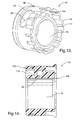
- Figures 13-16 show a fifth embodiment of the bearing 40 that incorporates the cavity 116 extending from the leading end 106 of the bearing 40.
- the fifth embodiment does not include a scallop 114 therefore the bearing 40 would be positioned in the chamber 44 next adjacent the pinion 36.
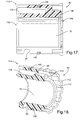
- Figures 17-19 show a sixth embodiment of the bearing 40 that incorporates the cavity 116 circumferentially around the leading end 106.
- the cavities 116 extend along the longitudinal axis 42 toward the trailing end 108 and are disposed between the outer face 68 and the inner face 70 of the bearing 40. Additionally the bearing 40 includes a scallop 114 in the bearing 40 wall 66.
- Figures 20 - 22 show a seventh embodiment of the bearing 40 incorporating the series of cavities 116 extending from the leading end 106 of the bearing 40 along the longitudinal axis 42 toward the trailing end 108. Additionally a scallop 114 extends a greater length into the wall 66 to narrow the bearing 40 width, which allows the bearing 40 to be positioned so a portion of the wall 66 of the bearing 40 in directly opposing the pinion 36 meshing with the rack 34.
- Figure 23 shows an eighth embodiment of the bearing 40 with the series of cavities 116 extending from the leading end 106 of the bearing 40.
- the eighth embodiment illustrates a scallop 114 and that the scallop 114 can vary in size and angle to further narrow the bearing 40 width in a portion of the wall 66 of the bearing 40. It is understood by one skilled in the art that the load requirements and desing of the housing 32 requires the bearing 40 to be flexible for positioning of the bearing 40 in the housing 32 near the meshing engagement between the rack 34 and pinion 36.
Landscapes
- Engineering & Computer Science (AREA)
- Mechanical Engineering (AREA)
- Combustion & Propulsion (AREA)
- Transportation (AREA)
- General Engineering & Computer Science (AREA)
- Chemical & Material Sciences (AREA)
- Transmission Devices (AREA)
- Support Of The Bearing (AREA)
- Steering Control In Accordance With Driving Conditions (AREA)
- Power Steering Mechanism (AREA)
- Harvester Elements (AREA)
- Gear Transmission (AREA)
- Automatic Cycles, And Cycles In General (AREA)
- Steering Controls (AREA)
Abstract
Description
- The present invention relates to a power steering apparatus for turning steerable wheels on a vehicle with an adjustment device to adjust a rack and pinion into proper meshing engagement.
- Power steering systems having a rack and a pinion are utilized in nearly all of today's vehicles to steer at least two of the wheels of a vehicle. The steering wheel of the vehicle is typically connected to a pinion gear that is in meshing engagement with a rack. The rack and pinion are supported in a housing and the rack translates the rotational movement of the pinion and steering wheel into a linear movement. The linear movement of the rack is translated to the steerable wheels of the car typically by a tie rod connected to each of the steerable wheels. In addition, power steering systems typically include an assisting force that provides a pressure or a force in proportion to the rotation of the steering wheel for assisting the linear movement of the rack. The assisting force is an additional systems that may be a hydraulic system utilizing a hydraulic piston coupled to the rack or electrical system utilizing an electric motor to supply the assisting force to the rack. In either system there is a desire to properly support and allow for adjustments to the meshing engagement between the pinion and the rack during the operational life of the power steering apparatus.
- The rack can be supported in the housing by a bearing to reduce the frictional resistance on the linear movement of the rack within the housing. The bearing also supports the rack and typically is adjustable to position the rack in proper meshing engagement with the pinion. The bearing, such as that disclosed in
United States Patent No. 6,247,375 , utilizes a yoke with a bearing surface that is eccentric to the housing to support and adjust the rack into proper meshing engagement with the pinion. The yoke is installed into a housing of the power steering assembly. Once installed, the yoke is rotated thereby adjusting the support and positioning the rack in proper meshing engagement with the pinion. The yoke is then permanently staked into position with a tool to deform the housing to support and secure the yoke in the rotated position. Since the yoke is staked into position the yoke and bearing support is not adjustable after the complete installation of the yoke into the assembly. Therefore the yoke does not allow for adjustment of the rack after the completed assembly of a vehicle, and further provides no adjustment during the operation of the power steering assembly. - Additional bearing designs such as the bearing disclosed in
United States Patent No. 6,435,050 , utilizes a two-piece bearing design with a complex assembly involved to support the rack in the housing. The rack bearing is complex with a multiple piece bearing surface and additional bushings are needed to support the rack in proper meshing engagement with the pinion. - Therefore there exists a need to provide a power steering apparatus with a bearing having few components to support the rack in proper meshing engagement with the pinion. In addition, some type of an adjustment device would be desirable for engaging the bearing to adjust the bearing to support the rack in proper meshing engagement with the pinion.
- The invention provides for a power steering apparatus comprising a housing that extends along a longitudinal axis. The housing further includes a chamber with an inner surface. A rack is disposed within the chamber and supported in the chamber for movement along the longitudinal axis. A pinion supported by the housing extends into the chamber for meshing with the rack. A bearing engages the inner surface of the chamber and is dispose around the rack to support the rack in the housing. The bearing includes a wall of a continuous varying radial thickness that circumferentially surrounds the rack. An adjustment device is supported by the housing and is connected to the bearing that rotatably adjusts the bearing relative to the longitudinal axis. The continuous varying radial thickness of the wall thereby positions the rack relative to the pinion ensuring proper meshing engagement between the rack and the pinion.
- The invention includes a bearing and an adjustment device engaging the bearing while reducing the complexity of the assembly. The adjustment device is of an eloquent design that can be adjusted throughout the operational life of the power steering apparatus.
- Other advantages of the present invention will be readily appreciated, as the same becomes better understood by reference to the following detailed description when considered in connection with the accompanying drawings wherein:
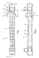
- Figure 1 is an elevated view of a housing for a power steering apparatus according to a first embodiment of the invention with a partial cutaway;
- Figure 2 is a cross-sectional view taken along section lines 2-2 in Figure 1;
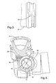
- Figure 3 is a detail view taken along
perspective arrow 3 in Figure 1; - Figure 4 is a cross-sectional view of the housing taken along section lines 4-4 in Figure 1;
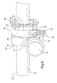
- Figure 5 is a partial sectional view of a rack and pinion of the power steering apparatus;
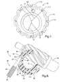
- Figure 6 is a partial perspective view of the rack supported in a bearing and in meshing engagement with the pinion;
- Figure 7 is a side view of the bearing shown in Figure 6;
- Figure 8 is a partial cross-sectional view showing the engagement between an adjustment device and the bearing;
- Figure 9 is a partial cross-sectional view showing the bearing in the housing and the engagement between the adjustment device, the bearing, and the rack;
- Figure 10 is a perspective view of a second embodiment of the bearing for supporting the rack in meshing engagement with the pinion;
- Figure 11 is a top view of a third embodiment of the bearing for supporting the rack in meshing engagement with the pinion;
- Figure 12 is a side view of a fourth embodiment of the bearing for supporting a rack having a Y-shaped configuration;
- Figure 13 is a perspective view of a fifth embodiment of the bearing for supporting the rack in meshing engagement with the pinion;
- Figure 14 is a cross-sectional view of the bearing of the fifth embodiment;
- Figure 15 is a cross-sectional perspective view of the bearing of the fifth embodiment;
- Figure 16 is another cross-sectional perspective view of the bearing of the fifth embodiment;
- Figure 17 is a cross-sectional view of a sixth embodiment of the bearing for supporting the rack in meshing engagement with the pinion;
- Figure 18 is a cross-sectional perspective view of the bearing of the sixth embodiment;
- Figure 19 is another cross-sectional perspective view of the bearing of the sixth embodiment;
- Figure 20 is a cross-sectional view of a seventh embodiment of the bearing for supporting the rack in meshing engagement with the pinion;
- Figure 21 is a cross-sectional perspective view of the bearing of the seventh embodiment;
- Figure 22 is another cross-sectional perspective view of the bearing of the seventh embodiment; and
- Figure 23 is a perspective view of an eighth embodiment of the bearing for supporting the rack in meshing engagement with the pinion.
- Referring to the Figures, wherein like numerals indicate corresponding parts throughout the several views, a power steering apparatus is shown generally at 30 in Figures 1 and 5. As best shown in Figures 1 and 2, the
power steering apparatus 30 includes ahousing 32 extending along alongitudinal axis 42. Thehousing 32 has achamber 44 that extends along thelongitudinal axis 42 and defines aninner surface 46, best shown in Figure 2. Thehousing 32 includes anaperture 48 that extends into thechamber 44 for receiving an adjustment device 38 (discussed in greater detail below). Thehousing 32 further includes anadjoining extension 50 that is connected to thechamber 44 and extends to rotatably support a pinion 36 (also discussed in greater detail below). Theadjoining extension 50 is generally transverse to thelongitudinal axis 42 and thechamber 44. Theinner surface 46 of thehousing 32 also includes agroove 52 that extends annularly around thelongitudinal axis 42 for positioning abearing 40 as will be fully discussed below. Referring to Figure 3, thehousing 32 can optionally include a marking 54 or other feature to aid the orientation and assembly of thebearing 40 into thehousing 32, the use in cooperation with thebearing 36 will be further discussed below. - As best shown in Figure 4, the
inner surface 46 defines twodiameters first diameter 56 having a center on thelongitudinal axis 42 and asecond diameter 58 having a center on asecond axis 60. The inner surface of the housing further includes ashoulder 62 between thefirst diameter 56 and thesecond diameter 58. Theshoulder 62 further includes a chamfer and a lead-in to create a more gradual transition between thefirst diameter 56 and theshoulder 62. Thefirst diameter 56 can be offset an amount which will vary depending on the design of theinner surface 46 and thebearing 40 to be supported within theinner surface 46. However, as is known in the art theinner surface 46 of thehousing 32 can have different diameters and configurations with varying offset distances between thelongitudinal axis 42 and thesecond axis 60. It is also appreciated that there can be no offset, which will depend on thebearing 40 design, therack 34 configuration, and the space and size constraints on thepower steering apparatus 30 within the given application. It is also appreciated by one skilled in the art that theinner surface 46 of thehousing 32 can be configured to various geometries for supporting and locating thebearing 40, and therack 34 within the housing, as will be further discussed below. - Referring to Figures 5 and 6, the
rack 34 is disposed within thechamber 44 of thehousing 32 and moves linearly along thelongitudinal axis 42 in response to rotational movement of thepinion 36 as is known in the art. Thepinion 36 is rotatably supported in the adjoiningextension 50 of the housing. As is known in the art the adjoiningextension 50 typically will include an area for press fitting a rotational support, i.e., a roller bearing, to support thepinion 36. Therack 34 defines a plurality ofteeth 64 for meshing with thepinion 36 as is well known in the art. Therack 34 translates the rotational movement of thepinion 36 to a linear movement. In a typical application, such as a passenger vehicle, thepinion 36 is connected to the steering wheel (not shown) and rotates in relationship to a movement of the steering wheel by a driver. Therack 34 translates the rotational movement of thepinion 36 into the linear movement which is connected to and moves the steerable wheels of a vehicle, typically through a tie rod engaging each of the steerable wheels. As known in the art, thepower steering apparatus 30 typically includes an assisting force (not shown) to move therack 34 within thehousing 32. The assisting force is commonly created by a mechanical system such as a hydraulic, an electric or various other assisting technologies as are known in the art. - Referring to Figures 5, 6, 7, 8 and 9, the
rack 34 is supported in thehousing 32 by thebearing 40. The bearing 40 of the subject invention includes awall 66 having a continuous varying radial thickness circumferentially surrounding therack 34 in thehousing 32. The wall of thebearing 40 has anouter face 68 and aninner face 70. The bearing 40 further provides a dampeningmechanism 100 for dampening the lash movements of therack 34 within the bearing 40 against theinner surface 46 of thehousing 32. Theouter face 68 provides for engagement with the dampeningmechanism 100 which could include many electrometric materials and configurations as one skilled in the art would recognize. The dampeningmechanism 100 can further be defined as an o-ring that engages theouter face 68 of thebearing 40. The o-ring is a polymeric material with elastic properties and thereby provides dampening of the lash movements of therack 34 relative to thepinion 36 andhousing 32. As shown in Figure 5 the o-ring engages into a channel in theouter face 68 and is disposed between theouter face 68 of thebearing 40 and theinner surface 46 of thehousing 32. - Referring to Figure 6, the
wall 66 of thebearing 40 can optionally define ascallop 114 extending inward along thelongitudinal axis 42. Thescallop 114 defines a cut-out from thewall 66 of thebearing 40 allowing the bearing 40 to be designed and positioned in thechamber 44 relatively close to thepinion 36 as shown in Figure 6. The bearing 40 being positioned near thepinion 36 allows for thebearing 40 to support therack 34 against bending and torsional forces caused by the meshing engagement with thepinion 36. Figure 6 shows thewall 66 of the bearing 40 with ascallop 114 which removes a portion of thewall 66 to allow thepinion 36 to engage and mesh with therack 34. Thescallop 114 therefore allows a portion of thewall 66 of bearing 40 to extend along therack 34 opposite thepinion 36 to support therack 34 in meshing engagement with thepinion 36. The position of thebearing 40 is important to support the opposing force caused by the meshing engagement between thepinion 36 and therack 34. The closer thebearing 40 is to the meshing location of thepinion 36 to therack 34 reduces a leverage force between the meshing engagement of therack 34 andpinion 36 and thebearing 40. The reduced leverage force thereby improves the support of therack 36 and prevents therack 36 from bending away from and out of proper engagement with thepinion 38. In addition, the bearing 40 position being near or under thepinion 36 decrease the probability of noise or vibration as a result of lash movements of therack 34 due to high application loads on theapparatus 30. - The bearing 40 additionally includes features to aid in locating and orienting the
bearing 40 within thechamber 44 of thehousing 32 during the assembly of theapparatus 30. As shown in Figure 7, thebearing 40 includes anorientation extension 104, which is a cylinder in this embodiment, for locating thebearing 40 relative to thehousing 32. For example, theorientation extension 104 can be used to locate the top or noon position of thebearing 40 or optionally align with the marking 54 on thehousing 32. The marking 54 was discussed above and is as shown in Figure 3. Thebearing 40 is preferably oriented in thechamber 44 relative to thehousing 32 such that a 10 to 12 degree rotation from nominal to increase clearance and to position therack 34 below thelongitudinal axis 42. By supporting therack 32 initially during assembly below the nominal position creates additional clearance between therack 34 andpinion 36. The clearance is needed to allow for thepinion 36 to be installed into theapparatus 30 in a meshing engagement with therack 34. However, one skilled in the art would recognize that there are numerous ways to orient thebearing 40 with the use of additional assembly tooling. The additional clearance is removed by anadjustment device 38 that rotates the bearing 40 to position therack 34 in a proper meshing engagement with thepinion 36, which will be discussed fully below. - The
groove 52 in theinner surface 46 of thehousing 32 provides a positive location and reference location for thebearing 40 within thechamber 44 of thehousing 32. Thewall 66 of thebearing 40 includes aleading end 106 and a trailingend 108 that define a bearing width. The trailingend 108 of thebearing 40 includes afinger 110 biased outward from the bearing 40 for engagement into thegroove 52 and provides a positive location to thebearing 40 within thechamber 44. Thefinger 110 removably locks the bearing 40 in engagement with thegroove 52 in thechamber 44 and allow for removal of thebearing 40 if needed without damaging thehousing 32 and/or thebearing 40. Optionally, the trailingend 108 can include a series of alternatingfingers 110 andnotches 112 circumferentially around thebearing 40, to engage thegroove 52 and position thebearing 40, as shown in Figure 7. The removable aspect of thebearing 40 is advantageous to allow for thebearing 40 to be removable from thehousing 32 without damaging theinner surface 46 of thehousing 32, which is an expense component to the manufacture and damage to theinner surface 46 could lead to a scrap part or additional machining cost to refinish theinner surface 46 of thehousing 32. - Additionally the trailing
end 108 of thebearing 40 can further include a stop that engages with therack 34. The stop may simply include theinner face 70 having a chamfer at a diameter that is less than an end diameter of therack 34. There is numerous ways thebearing 40 could prevent therack 34 from completely passing through thebearing 40, therefore creating a stop to the linear travel of therack 34 within thehousing 32. The use of thebearing 40 as a stop is particularly advantageous when the size of thehousing 32 is important and to eliminate the need for additional components or additional complexity to theinner surface 46 to design in a feature to limit the travel of therack 34 within thehousing 32. - The
wall 66 of thebearing 40 can additionally include features to improve the manufacturability thebearing 40. Thewall 66 can define acavity 116 or a series ofcavities 116 that extend from theleading end 106 along thelongitudinal axis 42 toward the trailingend 108 of thebearing 40. Thecavity 116 provides for an even cure of the polymer material of the bearing 40 during the manufacturing of thebearing 40. Figure 8 shows thewall 66 having a series ofcavities 116. Thecavities 116 increase the likelihood that the polymer material of thebearing 40 will evenly cure with little of no undulations to theinner surface 46 of thebearing 40. This is important since theinner surface 46 supports therack 34 and undulation or imperfection to theinner surface 46 can increase wear of thebearing 40 and increase frictional resistance to the linear movement of therack 34. - Referring to Figure 7, the
wall 66 of thebearing 40 includes theouter face 68 andinner face 70. Theouter face 68 is defined by anouter radius 72. Theouter face 68 is generally circular and defines an external circumference having afirst center point 74. Thewall 66 is further defined by theinner face 70 having aninner radius 76. Theinner face 70 is generally circular and defines an internal circumference having asecond center point 78. Thesecond center point 78 is spaced a distance from thefirst center point 74 to define an amount of eccentricity between the outer circumference and the inner circumference which thereby defines the varying radial thickness of thewall 66. The varying radial thickness is gradual allowing for a gradual and smooth adjustment of thebearing 40 by theadjustment device 38, as discussed below. - As shown in Figures 4 and 7, the
outer face 68 of thebearing 40 engages against theinner surface 46 where theinner surface 46 defines thesecond diameter 58. Theouter face 68 is slightly smaller than thesecond diameter 58 of theinner surface 46 to allow for thebearing 40 to be rotated by the adjustment device 38 (discussed below). As mentioned above, thefirst diameter 56 is centered on thelongitudinal axis 42 and thesecond diameter 58 is centered on thesecond axis 60. Thesecond axis 60 is offset from thelongitudinal axis 42 and the offset can vary. However, as shown, the offset is generally equal in an opposite direction to the amount of eccentricity between the first and second center points 74, 78 of thewall 66 of thebearing 40. In other words, the offset is equal and opposite to the varying radial thickness of thewall 66. Thefirst diameter 56 of theinner surface 46 allows for clearance between therack 34 and thehousing 32 as thebearing 40 is rotated by theadjustment device 38, as will be discussed below, to move therack 34 into proper meshing engagement with thepinion 36. Thesecond axis 60 and thereby thesecond diameter 56 being offset from thelongitudinal axis 42 is important for applications where thehousing 32 size is limited due to space concerns and constraints within the application of theapparatus 30. The offsetsecond axis 60 in combination with the varying radial thickness of thewall 66 of thebearing 40 allows for a smaller radial cross-section of thehousing 32 that still has sufficient clearance to adjust the position of therack 34 with theadjustment device 38, as discussed below. - Referring to Figure 8, the
bearing 40 is operatively connected to theadjustment device 38 that rotates the bearing 40 relative to thelongitudinal axis 42. The varying radial thickness of thewall 66 of thebearing 40 therefore moves therack 34 toward thepinion 36 as the radial thickness of thewall 66 supporting therack 34 increases and away from thepinion 36 as the radial thickness of thewall 66 supporting therack 34 decreases. Therack 34 is moved relative to thepinion 36 andhousing 32 by theadjustment device 38 rotating thebearing 40 thereby the varying the radial thickness of thewall 66 supporting therack 34 which positions therack 34 into proper meshing engagement with thepinion 36. Therefore, thebearing 40 adjusts therack 34 with a gradual movement relative tolongitudinal axis 42 as thebearing 40 is rotated by theadjustment device 38. The varying radial thickness of thewall 66 is at a minimum at a radial location where the internal circumference is closest to the external circumference. - The
wall 66 of thebearing 40 defines ahole 80 that extends to a distal end, and the distal end further defines aseat 82. Theadjustment device 38 couples with theseat 82 to allow for a push and pull rotation of thebearing 40 relative to the movement of theadjustment device 38 as shown by adirectional arrow 84. Thehole 80 has an elliptical shape with the diameter tapering in a generally conical fashion into a bulb shapedseat 82. The elliptical shape and conical geometry of thehole 80 allows for theadjustment device 38 to pivot in theseat 82. The geometry of thehole 80 is particularly important to allow theadjustment device 38 to pivot as thebearing 40 rotates about thelongitudinal axis 42 during the adjustment of thebearing 40. - The
adjustment device 38 preferably includes afastener 86, or set screw, for coupling with theseat 82 of thebearing 40. Thefastener 86 includes afirst end 88 that defines abulbous portion 90 and ashaft 92 that extends from thefirst end 88 to asecond end 94. Thebulbous portion 90 of thefastener 86 engages with theseat 82 of thebearing 40. Thefastener 86 pivots in theseat 82 of thebearing 40 as thebearing 40 is rotated about thelongitudinal axis 42 during the adjustment of thebearing 40. Theseat 82 of thebearing 40 can optionally include anannular projection 96 for thebulbous portion 90 of thefastener 86 to engage creating a coupling engagement between thefastener 86 and thebearing 40. Theannular projection 96 aids to provide a secure engagement so the bearing 40 can be rotated in two directions without thefastener 86 becoming disengaged from theseat 82 of thebearing 40. Therefore thebearing 40 is rotated in one direction with a push force when thefastener 86 is driven into theseat 82 and the opposite direction with a pull force when thefastener 86 is backed away from theseat 82. Thesecond end 94 of thefastener 86 defines a threadedportion 98 for engagement with theaperture 48 of thehousing 32 to that allow the tightening of thefastener 86 to push thebearing 40 and loosening of thefastener 86 to pull thebearing 40. Thebearing 40 is rotated relative to thelongitudinal axis 42 as thefastener 86 pivots in theseat 82 within thehole 80. Figure 9 illustrates a cross-sectional view of thehousing 32 with theadjustment device 38, including thefastener 86, and thebearing 40 to show the engagement between the components of theapparatus 30. It should be appreciated that theadjustment device 38 could be of any suitable design. - Optionally, the
adjustment device 38 can further include acoil spring 102, as shown in Figure 9. Thecoil spring 102 is disposed around theshaft 92 of thefastener 86 for biasing between the bearing 40 and thehousing 32. The biasing by thecoil spring 102 provides additional dampening for lash movements of therack 34 relative to thepinion 36. In addition, thecoil spring 102 provides a force that can further rotate thebearing 40 to maintain proper meshing engagement between therack 34 and thepinion 36. The rotation of thebearing 40 by thecoil spring 102 effectively provides operational adjustments to thebearing 40 as needed to compensate for additional clearance caused by wear on thebearing 40 over time with the operation of thepower steering apparatus 30. - The dampening
mechanism 100 and theouter face 68 of thebearing 40 provide a friction force against theinner surface 46 that locks the bearing 40 in position. The friction force provides a virtual lock of the bearing 40 in position and does not allowing the bearing 40 to rotate under high application loads to compress thecoil spring 102, thereby rotating thebearing 40. Therefore, the adjustment of thebearing 40 by thecoil spring 102 is effective in rotating the bearing 40 during the operation of theapparatus 30, and the friction force caused by the interface between theouter face 68 and the dampeningmechanism 100 with theinner surface 46 maintains the bearing 40 in position to prevent compression of thecoil spring 102. However, one skilled in the art would recognize that thecoil spring 102 is removable and only an additional option for providing a way to further dampen the lash movement in theapparatus 30 while providing an operational and continuous adjustment of thebearing 40 to compensate additional clearance caused by wear on thebearing 40 due to the operation of theapparatus 30. - Also, referring to Figure 10, the
fastener 86 can further include aseal 103 to retain thefastener 86 relative to thehousing 32. In alternative embodiments of the invention, lock tight or similar methods as are known in the art could optionally be disposed on the threads or tolerance stacking can be employed to retain thefastener 86 relative to thehousing 32. - There are several embodiments of the
bearing 40 shown in the Figures 10 - 23. Each of the embodiments further illustrates the flexibility and design alternatives to thewall 66 of thebearing 40 to createvarious bearings 40 each unique to an application, with various widths,scallop 114 designs andcavity 116 arrangements of thewall 66. The alternative embodiment of the bearing 40 in Figure 10 does not include ascallop 114, however, thefastener 86 utilizes the seal on thefastener 86. Thefastener 86 would engage with theaperture 48 of the housing 32 (not shown) to secure thefastener 86 in theapparatus 30. - Referring to Figure 11, a third embodiment of the
bearing 40 includes an increasedbearing 40 width that spans and supports a longer portion of therack 34. Theadditional bearing 40 width thereby enhances the load carrying capability of thebearing 40 for supporting therack 34 in meshing engagement with thepinion 36. An additional dampeningmechanism 100, an o-ring in this embodiment, is used to provide additional dampening of the lash movements of therack 34 relative to thepinion 36. - Figure 12 shows a fourth embodiment of the
bearing 40 and includes anadapter 118 that rotatably engages theinner face 70 of thebearing 40. Theadapter 118 defines anorifice 120 that has a configuration complementary with a configuration of therack 34. Theadapter 118 is typically used to support arack 34 having a Y-shaped rack configuration. The fourth embodiment bearing 40 also allows for theinner surface 46 of thehousing 32 to be a more simple tube design without the additional machining of the offsetsecond diameter 58, as is known in the art, and discussed above. Theadapter 118 is an additional component that is typically required for variable effortpower steering apparatus 30 that utilize the Y-shaped rack configuration. Also, as one skilled in the art would recognize theorifice 120 of theadapter 118 could optionally be a configuration complementary to any rack configuration. - Figures 13-16 show a fifth embodiment of the
bearing 40 that incorporates thecavity 116 extending from theleading end 106 of thebearing 40. However, the fifth embodiment does not include ascallop 114 therefore thebearing 40 would be positioned in thechamber 44 next adjacent thepinion 36. - Figures 17-19 show a sixth embodiment of the
bearing 40 that incorporates thecavity 116 circumferentially around theleading end 106. Thecavities 116 extend along thelongitudinal axis 42 toward the trailingend 108 and are disposed between theouter face 68 and theinner face 70 of thebearing 40. Additionally thebearing 40 includes ascallop 114 in thebearing 40wall 66. - Figures 20 - 22 show a seventh embodiment of the
bearing 40 incorporating the series ofcavities 116 extending from theleading end 106 of thebearing 40 along thelongitudinal axis 42 toward the trailingend 108. Additionally ascallop 114 extends a greater length into thewall 66 to narrow thebearing 40 width, which allows the bearing 40 to be positioned so a portion of thewall 66 of the bearing 40 in directly opposing thepinion 36 meshing with therack 34. - Figure 23 shows an eighth embodiment of the bearing 40 with the series of
cavities 116 extending from theleading end 106 of thebearing 40. In addition the eighth embodiment illustrates ascallop 114 and that thescallop 114 can vary in size and angle to further narrow thebearing 40 width in a portion of thewall 66 of thebearing 40. It is understood by one skilled in the art that the load requirements and desing of thehousing 32 requires the bearing 40 to be flexible for positioning of the bearing 40 in thehousing 32 near the meshing engagement between therack 34 andpinion 36. - Obviously, many modifications and variations of the present invention are possible in light of the above teachings. The invention may be practiced otherwise than as specifically described within the scope of the appended claims.
Claims (19)
- A power steering apparatus (30), comprising:a housing (32) extending along a longitudinal axis (34) and having a chamber (36) with an inner surface (38);a rack (40) disposed within said chamber (36) for movement along said longitudinal axis (34);a pinion (42) supported by said housing (32) and extending into said chamber (36) for meshing with said rack (40);a bearing (44) engaging said inner surface (38) of said chamber (36) and disposed about said rack (40) with said bearing (44) having a wall (46) of a continuous varying radial thickness circumferentially surrounding said rack (40); andan adjustment device (48) supported by said housing (32) and connected to said bearing (44) for rotatably adjusting said bearing (44) relative to said axis thereby moving said rack (40) relative to said pinion (42) for ensuring proper meshing engagement for said pinion (42) with said rack (40).
- An apparatus (30) as set forth in claim 1 wherein said wall (46) of said bearing (44) further defines a hole (50) extending to a distal end defining a seat (52) with said adjustment device (48) coupling to said seat (52).
- An apparatus (30) as set forth in claim 2 wherein said adjustment device (48) further includes a fastener (54) having a first end (56) defining a bulbous portion (58) for engagement with said seat (52) and a shaft (60) extending from said first end (56) to a second end (62) for engagement with said housing (32).
- An apparatus (30) as set forth in claim 3 wherein said seat (52) further defines an annular projection (64) with said bulbous portion (58) of said fastener (54) engaging said annular projection (64).
- An apparatus (30) as set forth in claim 3 wherein said adjustment device (48) further includes a coil spring (66) disposed around said shaft (60) of said fastener (54) for biasing between said bearing (44) and said inner surface (38).
- An apparatus (30) as set forth in claim 3 wherein said housing (32) further includes an aperture (68) extending into said chamber (36) for receiving said fastener (54) of said adjustment device (48).
- An apparatus (30) as set forth in claim 6 wherein said second end (62) of said fastener (54) further defines a threaded portion (70) for engagement with said aperture (68) of said housing (32).
- An apparatus (30) as set forth in claim 1 wherein said wall (46) extends along said longitudinal axis (34) between a leading end (72) and a trailing end (74) with said trailing end (74) defining a stop to limit the movement of said rack (40) in said chamber (36).
- An apparatus (30) as set forth in claim 1 wherein said inner surface (38) of said housing (32) further includes a groove (76) extending annularly around said longitudinal axis (34) for positioning said bearing (44).
- An apparatus (30) as set forth in claim 9 wherein said bearing (44) further includes a finger (78) biasing outward from said bearing (44) for engagement into said groove (76) to position said bearing (44) in said chamber (36).
- An apparatus (30) as set forth in claim 9 wherein said wall (46) has a leading end (72) and a trailing end (74) and said trailing end (74) further defines a series of alternating fingers (78) and notches (80) circumferentially around said bearing (44) and said series of fingers (78) biasing outward from said bearing (44) for engagement with said groove (76) to position said bearing (44) in said chamber (36).
- An apparatus (30) as set forth in claim 1 wherein said wall (46) of said bearing (44) includes an outer face (82) having an outer radius (84) and an inner face (86) having an inner radius (88) that is off center a distance from said outer radius (84) to define said varying radial thickness of said wall (46).
- An apparatus (30) as set forth in claim 12 wherein said bearing (44) further includes an adapter (90) rotatably engaged with said inner face (86) with said adapter (90) defining an orifice (92) having a configuration complementary with a configuration of said rack (40).
- An apparatus (30) as set forth in claim 1 wherein said wall (46) of said bearing (44) is defined by an outer face (82) defining an external circumference having a first center point (94) and an inner face (86) defining an internal circumference having a second center point (96) and said second center point (96) eccentric from said first center point (94) to define said varying radial thickness of said wall (46).
- An apparatus (30) as set forth in claim 14 wherein said varying radial thickness defines a minimum radial thickness where said internal circumference is closest to said external circumference.
- An apparatus (30) as set forth in claim 1 wherein said bearing (44) further includes a dampening mechanism (98) for dampening lash movements between said rack (40) and said pinion (42).
- An apparatus (30) as set forth in claim 1 wherein said wall (46) further defines a bearing (44) width extending between a leading end (72) and a trailing end (74) and said leading end (72) is further defined by at least one scallop (100) extending inward along said longitudinal axis (34) into said wall (46) of said bearing (44) for allowing said bearing (44) to be positioned under said pinion (42).
- An apparatus (30) as set forth in claim 1 wherein said wall (46) has a leading end (72) and a trailing end (74) and said trailing end (74) further includes an orientation extension (102) for locating said bearing (44) relative to said housing (32) during the assembly of said bearing (44) into said chamber (36).
- An apparatus (30) as set forth in claim 1 wherein said wall (46) further defines a bearing (44) width extending between a leading end (72) and a trailing end (74) and said wall (46) further defines a cavity (104) extending along said longitudinal axis (34) from said leading end (72) between said outer and inner faces (82, 86) for improving cure characteristics of said bearing (44).
Priority Applications (1)
| Application Number | Priority Date | Filing Date | Title |
|---|---|---|---|
| PL06076222T PL1738989T3 (en) | 2005-06-30 | 2006-06-14 | Power steering apparatus with adjustment device |
Applications Claiming Priority (2)
| Application Number | Priority Date | Filing Date | Title |
|---|---|---|---|
| US69549405P | 2005-06-30 | 2005-06-30 | |
| US11/409,111 US8555741B2 (en) | 2005-06-30 | 2006-04-21 | Power steering apparatus with adjustment device |
Publications (2)
| Publication Number | Publication Date |
|---|---|
| EP1738989A1 true EP1738989A1 (en) | 2007-01-03 |
| EP1738989B1 EP1738989B1 (en) | 2009-02-11 |
Family
ID=37056925
Family Applications (1)
| Application Number | Title | Priority Date | Filing Date |
|---|---|---|---|
| EP06076222A Not-in-force EP1738989B1 (en) | 2005-06-30 | 2006-06-14 | Power steering apparatus with adjustment device |
Country Status (6)
| Country | Link |
|---|---|
| US (1) | US8555741B2 (en) |
| EP (1) | EP1738989B1 (en) |
| CN (1) | CN100594150C (en) |
| AT (1) | ATE422452T1 (en) |
| DE (1) | DE602006005106D1 (en) |
| PL (1) | PL1738989T3 (en) |
Cited By (8)
| Publication number | Priority date | Publication date | Assignee | Title |
|---|---|---|---|---|
| EP1992546A1 (en) | 2007-05-14 | 2008-11-19 | Delphi Technologies, Inc. | Rack and Pinion Steering Gear Assembly having selfadjusting eccentric Rack Bearing |
| EP1992545A1 (en) | 2007-05-14 | 2008-11-19 | Delphi Technologies, Inc. | Rack and pinion steering apparatus having rack bearing waer compensation with damping |
| EP2233381A1 (en) * | 2009-03-27 | 2010-09-29 | ThyssenKrupp Presta AG | Cost-effective gear rack steering gear |
| WO2011048328A1 (en) * | 2009-10-23 | 2011-04-28 | Jtekt Europe | Push device with clearance compensation for rack-and-pinion steering of a motor vehicle |
| US7980152B2 (en) | 2005-06-30 | 2011-07-19 | Nexteer (Beijing) Technology Co., Ltd. | Rack and pinion steering gear assembly having self-adjusting eccentric rack bearing |
| DE102012019655A1 (en) * | 2012-10-08 | 2014-04-10 | Thyssenkrupp Presta Aktiengesellschaft | Rack and pinion steering gear |
| DE102012019654A1 (en) * | 2012-10-08 | 2014-04-10 | Thyssenkrupp Presta Aktiengesellschaft | Rack and pinion steering gear |
| PL447119A1 (en) * | 2023-12-15 | 2025-06-16 | Steering Solutions Ip Holding Corporation | Wedge sleeve for steering rack and pinion assembly |
Families Citing this family (24)
| Publication number | Priority date | Publication date | Assignee | Title |
|---|---|---|---|---|
| US8336413B2 (en) * | 2005-06-30 | 2012-12-25 | Steering Solutions Ip Holding Corporation | Rack and pinion steering apparatus having rack bearing wear compensation with damping |
| GB2437531B (en) * | 2006-04-26 | 2008-03-26 | Forac Ltd | Actuator with spring return piston |
| FR2938034B1 (en) * | 2008-11-06 | 2011-10-07 | Jtekt Europe Sas | ECCENTRIC PUSH-BUTTON DEVICE FOR DIRECTION OF A MOTOR VEHICLE |
| DE102011075496A1 (en) * | 2011-05-09 | 2012-11-15 | Schaeffler Technologies AG & Co. KG | Pressure piece of a rack and pinion steering |
| FR2978111B1 (en) * | 2011-07-22 | 2013-08-09 | Peugeot Citroen Automobiles Sa | VEHICLE STEERING SYSTEM RACK MECHANISM WITH COUPLING INTERFACE |
| US8863599B2 (en) * | 2011-11-08 | 2014-10-21 | Ford Global Technologies, Llc | Yoke assembly for power steering rack and pinion gear set |
| WO2013124308A2 (en) * | 2012-02-20 | 2013-08-29 | Schmittergroup Ag | Gear rack steering gear having a progressive reduction |
| DE102012103147A1 (en) * | 2012-04-12 | 2013-10-17 | Zf Lenksysteme Gmbh | LOS BEARING FOR A STEERING GEAR |
| FR2992280B1 (en) * | 2012-06-25 | 2014-06-20 | Jtekt Europe Sas | ECCENTRIC PUSH BUTTON WITH GAME COMPENSATION FOR MOTOR VEHICLE DIRECTION |
| JP5778123B2 (en) * | 2012-12-25 | 2015-09-16 | 日立オートモティブシステムズステアリング株式会社 | Power steering device and backlash adjustment mechanism |
| US9873448B2 (en) | 2014-03-31 | 2018-01-23 | Steering Solutions Ip Holding Corporation | End of travel stop |
| JP6528969B2 (en) * | 2015-08-21 | 2019-06-12 | 株式会社ジェイテクト | Steering device |
| CN105460075B (en) * | 2015-12-16 | 2018-06-22 | 上汽通用五菱汽车股份有限公司 | A kind of rack of steering clearance control method |
| CN105805251A (en) * | 2016-05-16 | 2016-07-27 | 新乡艾迪威汽车科技有限公司 | Rack and gear meshing clearance adjusting mechanism for automobile steering device |
| KR102346287B1 (en) * | 2017-05-22 | 2022-01-04 | 주식회사 만도 | Dust cap for steering apparatus of vehicle |
| DE102017212073A1 (en) | 2017-07-14 | 2019-01-17 | Ford Global Technologies, Llc | Rack and pinion for a motor vehicle |
| JP6964783B2 (en) * | 2017-12-29 | 2021-11-10 | サン−ゴバン パフォーマンス プラスチックス パンプス ゲゼルシャフト ミット ベシュレンクテル ハフツング | Steering assembly |
| CN108340964B (en) * | 2018-02-01 | 2024-03-08 | 阿尔特汽车技术股份有限公司 | Gear rack steering gear centering additional mechanism |
| CN108706043B (en) * | 2018-05-27 | 2023-07-25 | 豫北转向系统(新乡)股份有限公司 | Rack supporting structure of automobile steering gear |
| CN110805690A (en) * | 2019-12-04 | 2020-02-18 | 无锡京华重工装备制造有限公司 | A crack structure disappears for merry go round machine C axle |
| CN111422242B (en) * | 2020-04-08 | 2021-09-10 | 福建盛海智能科技有限公司 | Steering structure |
| FR3123880B1 (en) * | 2021-06-14 | 2024-03-29 | Jtekt Europe Sas | Guide bearing of a rack of a steering system |
| PL439779A1 (en) * | 2021-12-08 | 2023-06-12 | Steering Solutions Ip Holding Corporation | Steering rack bending limiter |
| CN116461595A (en) * | 2023-05-30 | 2023-07-21 | 株洲易力达机电有限公司 | A new gear rack clearance adjustment mechanism and automobile steering gear |
Citations (5)
| Publication number | Priority date | Publication date | Assignee | Title |
|---|---|---|---|---|
| GB655130A (en) * | 1948-07-09 | 1951-07-11 | Cam Gears Ltd | Improvements in vehicular steering gear |
| US3820415A (en) * | 1973-03-01 | 1974-06-28 | Trw Inc | Rack and pinion assembly |
| EP1046569A1 (en) * | 1999-04-23 | 2000-10-25 | TRW Inc. | Apparatus for turning steerable vehicle wheels |
| EP1067037A1 (en) * | 1999-07-06 | 2001-01-10 | Société de Mécanique d'Irigny | Rack and pinion steering for a motor vehicle |
| US6435050B1 (en) | 2001-03-28 | 2002-08-20 | Delphi Technologies, Inc. | Steering gear for motor vehicle |
Family Cites Families (41)
| Publication number | Priority date | Publication date | Assignee | Title |
|---|---|---|---|---|
| US1443685A (en) * | 1919-12-30 | 1923-01-30 | Dodge Brothers | Steering gear |
| US1592714A (en) | 1922-05-31 | 1926-07-13 | Charles H Biederman | Reduction gear |
| US1565264A (en) * | 1924-03-22 | 1925-12-15 | Dubi Boris | Adjustable eccentric |
| US1706809A (en) | 1925-06-08 | 1929-03-26 | Gemmer Mfg Co | Worm-gear adjustment for motor-vehicle steering gears |
| US1910300A (en) * | 1928-05-07 | 1933-05-23 | Gemmer Mfg Co | Bushing for motor car steering columns |
| BE414494A (en) * | 1935-04-01 | 1900-01-01 | ||
| FR862805A (en) | 1940-01-09 | 1941-03-17 | Adjusting device for steering mechanism for motor vehicles | |
| US3054321A (en) * | 1959-07-15 | 1962-09-18 | Macchia Anthony | Screw assembly with ball and socket connection |
| DE2037440C3 (en) * | 1970-07-28 | 1973-11-15 | Glyco-Metallwerke Daelen & Loos Gmbh, 6200 Wiesbaden-Schierstein | Plain bearing with adjustable radial play |
| DE2056066C3 (en) * | 1970-11-14 | 1979-11-15 | Daimler-Benz Ag, 7000 Stuttgart | Disconnection device for the hydraulic auxiliary power in a power steering system for vehicles |
| US3753375A (en) | 1971-11-29 | 1973-08-21 | Trw Inc | Rack and pinion steering gear |
| US3908479A (en) | 1973-12-10 | 1975-09-30 | Stanley I Macduff | Variable ratio rack and pinion power steering gear |
| DE2606365A1 (en) | 1976-02-18 | 1977-08-25 | Volkswagenwerk Ag | RACK STEERING FOR MOTOR VEHICLES |
| US4218933A (en) | 1978-10-10 | 1980-08-26 | Cam Gears Limited | Rack and pinion gear assembly |
| DE3321708A1 (en) | 1983-06-16 | 1984-12-20 | Závody silnoproudé elektrotechniky koncern Praha MEZ Mohelnice, koncernový podnik, Mohelnice | GEARBOX WITH A DEVICE FOR DAMAGE-FREE GEARING OF A GEAR |
| JPS6038258A (en) | 1983-08-09 | 1985-02-27 | Nissan Motor Co Ltd | Protective cover setting structure for rack-and-pinion type steering device |
| DE3534577C2 (en) | 1985-09-27 | 1993-11-18 | Atsugi Motor Parts Co Ltd | Hydraulic rack and pinion steering |
| DE3543563C1 (en) * | 1985-12-10 | 1987-05-07 | Hella Kg Hueck & Co | Vehicle headlights |
| JPH0740245Y2 (en) * | 1989-07-27 | 1995-09-13 | スタンレー電気株式会社 | head lamp |
| JPH0639161Y2 (en) | 1989-11-06 | 1994-10-12 | 株式会社椿本チエイン | Intermittent drive input shaft mounting structure |
| JPH0736868Y2 (en) * | 1990-03-20 | 1995-08-23 | ティーアールダブリュエスアイ株式会社 | Valve assembly structure in power steering system |
| US5070957A (en) * | 1990-11-20 | 1991-12-10 | General Motors Corporation | Variable effort automotive power steering gear |
| EP0507164A3 (en) * | 1991-04-02 | 1993-04-07 | Koyo Seiko Co., Ltd. | Back and pinion type steering apparatus |
| JP3158346B2 (en) | 1991-08-26 | 2001-04-23 | ボッシュ ブレーキ システム株式会社 | Rack and pinion type steering device |
| DE4232813A1 (en) * | 1992-09-30 | 1994-03-31 | Zahnradfabrik Friedrichshafen | Centering device, in particular for steering valves |
| US5509186A (en) * | 1994-12-02 | 1996-04-23 | Straut; Nelson F. | Bearing pusher |
| DE19539864C1 (en) | 1995-10-26 | 1997-01-23 | Trw Fahrwerksyst Gmbh & Co | Rattle-free rack=and=pinion drive, esp. for steering on vehicle |
| JPH09204803A (en) * | 1996-01-29 | 1997-08-05 | Koito Mfg Co Ltd | Headlight aiming device |
| JP2000264234A (en) | 1999-03-12 | 2000-09-26 | Showa Corp | Power steering device |
| BR0000567A (en) | 1999-04-12 | 2000-10-31 | Visteon Automotive Systems Inc | Improvement in steering mechanisms and adjustable assembly for pinions of assisted mechanisms for motor vehicles |
| US6485180B2 (en) * | 2001-01-04 | 2002-11-26 | Delphi Technologies, Inc. | Expandable rack bushing |
| EP1245509B1 (en) * | 2001-03-29 | 2005-09-14 | Spiroflow Systems Inc. | Tension control apparatus and method for aero-mechanical conveyor |
| DE20114759U1 (en) | 2001-09-06 | 2002-01-17 | TRW Fahrwerksysteme GmbH & Co KG, 40547 Düsseldorf | steering gear |
| JP4657590B2 (en) * | 2002-08-28 | 2011-03-23 | オイレス工業株式会社 | Sliding bearing and bearing mechanism including the same |
| US20040107787A1 (en) | 2002-12-04 | 2004-06-10 | Bernard Petrillo | Backlash-free rack and pinion |
| WO2004067357A1 (en) | 2003-01-28 | 2004-08-12 | Schmitterchassis Gmbh | Motor vehicle steering gear comprising a gear rack and a bearing module therefor |
| JP2004232788A (en) | 2003-01-31 | 2004-08-19 | Kayaba Ind Co Ltd | Power transmission device |
| US7401789B2 (en) * | 2005-06-07 | 2008-07-22 | Trw Automotive U.S. Llc | Rack bushing for rack and pinion steering assembly |
| KR20070092018A (en) | 2006-03-08 | 2007-09-12 | 주식회사 만도 | Support yoke automatic play compensation for rack pinion type steering system |
| US7665747B2 (en) * | 2006-10-13 | 2010-02-23 | Gm Global Technology Operations, Inc. | Steering gear assembly having rack bushing |
| US20100061798A1 (en) * | 2008-09-11 | 2010-03-11 | Austin Unsworth | Pivot bearing with adjustable resistance |
-
2006
- 2006-04-21 US US11/409,111 patent/US8555741B2/en not_active Expired - Fee Related
- 2006-06-14 EP EP06076222A patent/EP1738989B1/en not_active Not-in-force
- 2006-06-14 PL PL06076222T patent/PL1738989T3/en unknown
- 2006-06-14 AT AT06076222T patent/ATE422452T1/en not_active IP Right Cessation
- 2006-06-14 DE DE602006005106T patent/DE602006005106D1/en active Active
- 2006-06-29 CN CN200610099662A patent/CN100594150C/en not_active Expired - Fee Related
Patent Citations (5)
| Publication number | Priority date | Publication date | Assignee | Title |
|---|---|---|---|---|
| GB655130A (en) * | 1948-07-09 | 1951-07-11 | Cam Gears Ltd | Improvements in vehicular steering gear |
| US3820415A (en) * | 1973-03-01 | 1974-06-28 | Trw Inc | Rack and pinion assembly |
| EP1046569A1 (en) * | 1999-04-23 | 2000-10-25 | TRW Inc. | Apparatus for turning steerable vehicle wheels |
| EP1067037A1 (en) * | 1999-07-06 | 2001-01-10 | Société de Mécanique d'Irigny | Rack and pinion steering for a motor vehicle |
| US6435050B1 (en) | 2001-03-28 | 2002-08-20 | Delphi Technologies, Inc. | Steering gear for motor vehicle |
Cited By (12)
| Publication number | Priority date | Publication date | Assignee | Title |
|---|---|---|---|---|
| US7980152B2 (en) | 2005-06-30 | 2011-07-19 | Nexteer (Beijing) Technology Co., Ltd. | Rack and pinion steering gear assembly having self-adjusting eccentric rack bearing |
| EP1992546A1 (en) | 2007-05-14 | 2008-11-19 | Delphi Technologies, Inc. | Rack and Pinion Steering Gear Assembly having selfadjusting eccentric Rack Bearing |
| EP1992545A1 (en) | 2007-05-14 | 2008-11-19 | Delphi Technologies, Inc. | Rack and pinion steering apparatus having rack bearing waer compensation with damping |
| EP2233381A1 (en) * | 2009-03-27 | 2010-09-29 | ThyssenKrupp Presta AG | Cost-effective gear rack steering gear |
| WO2011048328A1 (en) * | 2009-10-23 | 2011-04-28 | Jtekt Europe | Push device with clearance compensation for rack-and-pinion steering of a motor vehicle |
| FR2951797A1 (en) * | 2009-10-23 | 2011-04-29 | Jtekt Europe Sas | PUSH-BUTTON DEVICE WITH GAME COMPENSATION FOR DIRECTION WITH RACK OF MOTOR VEHICLE |
| US8931790B2 (en) | 2009-10-23 | 2015-01-13 | Jtekt Europe | Push device with clearance compensation for rack-and-pinion steering of a motor vehicle |
| DE102012019655A1 (en) * | 2012-10-08 | 2014-04-10 | Thyssenkrupp Presta Aktiengesellschaft | Rack and pinion steering gear |
| DE102012019654A1 (en) * | 2012-10-08 | 2014-04-10 | Thyssenkrupp Presta Aktiengesellschaft | Rack and pinion steering gear |
| WO2014056570A1 (en) * | 2012-10-08 | 2014-04-17 | Thyssenkrupp Presta Ag | Rack-and-pinion steering gear |
| WO2014056571A1 (en) * | 2012-10-08 | 2014-04-17 | Thyssenkrupp Presta Ag | Rack-and-pinion steering gear |
| PL447119A1 (en) * | 2023-12-15 | 2025-06-16 | Steering Solutions Ip Holding Corporation | Wedge sleeve for steering rack and pinion assembly |
Also Published As
| Publication number | Publication date |
|---|---|
| CN1895946A (en) | 2007-01-17 |
| PL1738989T3 (en) | 2009-06-30 |
| DE602006005106D1 (en) | 2009-03-26 |
| ATE422452T1 (en) | 2009-02-15 |
| US20070000341A1 (en) | 2007-01-04 |
| US8555741B2 (en) | 2013-10-15 |
| CN100594150C (en) | 2010-03-17 |
| EP1738989B1 (en) | 2009-02-11 |
Similar Documents
| Publication | Publication Date | Title |
|---|---|---|
| EP1738989B1 (en) | Power steering apparatus with adjustment device | |
| KR102281674B1 (en) | Reducer for vehicle | |
| EP1911658B1 (en) | Steering gear assembly having rack bushing | |
| US8336413B2 (en) | Rack and pinion steering apparatus having rack bearing wear compensation with damping | |
| US10059366B2 (en) | Electrically driven power steering device | |
| EP1035355B1 (en) | Rotation stop device | |
| JP2942496B2 (en) | Detent mechanism for screw type linear actuator | |
| EP2916042B1 (en) | Electric linear actuator | |
| US10183693B2 (en) | Electric power steering device | |
| EP3267072A2 (en) | Actuator for providing relative motion between two points | |
| US7980152B2 (en) | Rack and pinion steering gear assembly having self-adjusting eccentric rack bearing | |
| US6142031A (en) | Yoke apparatus for rack and pinion | |
| EP2722254A1 (en) | Electric power steering apparatus | |
| US20120067151A1 (en) | Worm drive | |
| US20180201304A1 (en) | Dual-pinion electric power steering device | |
| CN102730051A (en) | Vehicle steering device | |
| KR20070062954A (en) | Power steering apparatus with adjustment device | |
| US20090120226A1 (en) | Rack and pinion type steering device and method of manufacturing the same | |
| US6439337B1 (en) | Steering mechanism assembly for automotive vehicles | |
| US20070144854A1 (en) | Two-way clutch | |
| US20120011951A1 (en) | Linear actuator | |
| EP1992545B1 (en) | Rack and pinion steering apparatus having rack bearing waer compensation with damping | |
| EP1992546A1 (en) | Rack and Pinion Steering Gear Assembly having selfadjusting eccentric Rack Bearing | |
| EP1867552A1 (en) | Rack-pinion steering gear | |
| CN111868402B (en) | Bevel gear transmission comprising a pivot bearing with a defined pivot axis |
Legal Events
| Date | Code | Title | Description |
|---|---|---|---|
| PUAI | Public reference made under article 153(3) epc to a published international application that has entered the european phase |
Free format text: ORIGINAL CODE: 0009012 |
|
| AK | Designated contracting states |
Kind code of ref document: A1 Designated state(s): AT BE BG CH CY CZ DE DK EE ES FI FR GB GR HU IE IS IT LI LT LU LV MC NL PL PT RO SE SI SK TR |
|
| AX | Request for extension of the european patent |
Extension state: AL BA HR MK YU |
|
| 17P | Request for examination filed |
Effective date: 20070703 |
|
| 17Q | First examination report despatched |
Effective date: 20070803 |
|
| AKX | Designation fees paid |
Designated state(s): AT BE BG CH CY CZ DE DK EE ES FI FR GB GR HU IE IS IT LI LT LU LV MC NL PL PT RO SE SI SK TR |
|
| GRAP | Despatch of communication of intention to grant a patent |
Free format text: ORIGINAL CODE: EPIDOSNIGR1 |
|
| GRAS | Grant fee paid |
Free format text: ORIGINAL CODE: EPIDOSNIGR3 |
|
| GRAA | (expected) grant |
Free format text: ORIGINAL CODE: 0009210 |
|
| AK | Designated contracting states |
Kind code of ref document: B1 Designated state(s): AT BE BG CH CY CZ DE DK EE ES FI FR GB GR HU IE IS IT LI LT LU LV MC NL PL PT RO SE SI SK TR |
|
| REG | Reference to a national code |
Ref country code: GB Ref legal event code: FG4D |
|
| REG | Reference to a national code |
Ref country code: CH Ref legal event code: EP |
|
| REG | Reference to a national code |
Ref country code: IE Ref legal event code: FG4D |
|
| REF | Corresponds to: |
Ref document number: 602006005106 Country of ref document: DE Date of ref document: 20090326 Kind code of ref document: P |
|
| REG | Reference to a national code |
Ref country code: PL Ref legal event code: T3 |
|
| PG25 | Lapsed in a contracting state [announced via postgrant information from national office to epo] |
Ref country code: NL Free format text: LAPSE BECAUSE OF FAILURE TO SUBMIT A TRANSLATION OF THE DESCRIPTION OR TO PAY THE FEE WITHIN THE PRESCRIBED TIME-LIMIT Effective date: 20090211 Ref country code: LT Free format text: LAPSE BECAUSE OF FAILURE TO SUBMIT A TRANSLATION OF THE DESCRIPTION OR TO PAY THE FEE WITHIN THE PRESCRIBED TIME-LIMIT Effective date: 20090211 Ref country code: SI Free format text: LAPSE BECAUSE OF FAILURE TO SUBMIT A TRANSLATION OF THE DESCRIPTION OR TO PAY THE FEE WITHIN THE PRESCRIBED TIME-LIMIT Effective date: 20090211 Ref country code: FI Free format text: LAPSE BECAUSE OF FAILURE TO SUBMIT A TRANSLATION OF THE DESCRIPTION OR TO PAY THE FEE WITHIN THE PRESCRIBED TIME-LIMIT Effective date: 20090211 Ref country code: ES Free format text: LAPSE BECAUSE OF FAILURE TO SUBMIT A TRANSLATION OF THE DESCRIPTION OR TO PAY THE FEE WITHIN THE PRESCRIBED TIME-LIMIT Effective date: 20090522 |
|
| NLV1 | Nl: lapsed or annulled due to failure to fulfill the requirements of art. 29p and 29m of the patents act | ||
| PG25 | Lapsed in a contracting state [announced via postgrant information from national office to epo] |
Ref country code: LV Free format text: LAPSE BECAUSE OF FAILURE TO SUBMIT A TRANSLATION OF THE DESCRIPTION OR TO PAY THE FEE WITHIN THE PRESCRIBED TIME-LIMIT Effective date: 20090211 Ref country code: IS Free format text: LAPSE BECAUSE OF FAILURE TO SUBMIT A TRANSLATION OF THE DESCRIPTION OR TO PAY THE FEE WITHIN THE PRESCRIBED TIME-LIMIT Effective date: 20090611 Ref country code: SE Free format text: LAPSE BECAUSE OF FAILURE TO SUBMIT A TRANSLATION OF THE DESCRIPTION OR TO PAY THE FEE WITHIN THE PRESCRIBED TIME-LIMIT Effective date: 20090511 Ref country code: AT Free format text: LAPSE BECAUSE OF FAILURE TO SUBMIT A TRANSLATION OF THE DESCRIPTION OR TO PAY THE FEE WITHIN THE PRESCRIBED TIME-LIMIT Effective date: 20090211 |
|
| PG25 | Lapsed in a contracting state [announced via postgrant information from national office to epo] |
Ref country code: BE Free format text: LAPSE BECAUSE OF FAILURE TO SUBMIT A TRANSLATION OF THE DESCRIPTION OR TO PAY THE FEE WITHIN THE PRESCRIBED TIME-LIMIT Effective date: 20090211 |
|
| PG25 | Lapsed in a contracting state [announced via postgrant information from national office to epo] |
Ref country code: DK Free format text: LAPSE BECAUSE OF FAILURE TO SUBMIT A TRANSLATION OF THE DESCRIPTION OR TO PAY THE FEE WITHIN THE PRESCRIBED TIME-LIMIT Effective date: 20090211 Ref country code: PT Free format text: LAPSE BECAUSE OF FAILURE TO SUBMIT A TRANSLATION OF THE DESCRIPTION OR TO PAY THE FEE WITHIN THE PRESCRIBED TIME-LIMIT Effective date: 20090713 Ref country code: EE Free format text: LAPSE BECAUSE OF FAILURE TO SUBMIT A TRANSLATION OF THE DESCRIPTION OR TO PAY THE FEE WITHIN THE PRESCRIBED TIME-LIMIT Effective date: 20090211 |
|
| PG25 | Lapsed in a contracting state [announced via postgrant information from national office to epo] |
Ref country code: SK Free format text: LAPSE BECAUSE OF FAILURE TO SUBMIT A TRANSLATION OF THE DESCRIPTION OR TO PAY THE FEE WITHIN THE PRESCRIBED TIME-LIMIT Effective date: 20090211 Ref country code: RO Free format text: LAPSE BECAUSE OF FAILURE TO SUBMIT A TRANSLATION OF THE DESCRIPTION OR TO PAY THE FEE WITHIN THE PRESCRIBED TIME-LIMIT Effective date: 20090211 |
|
| PLBE | No opposition filed within time limit |
Free format text: ORIGINAL CODE: 0009261 |
|
| STAA | Information on the status of an ep patent application or granted ep patent |
Free format text: STATUS: NO OPPOSITION FILED WITHIN TIME LIMIT |
|
| 26N | No opposition filed |
Effective date: 20091112 |
|
| PG25 | Lapsed in a contracting state [announced via postgrant information from national office to epo] |
Ref country code: BG Free format text: LAPSE BECAUSE OF FAILURE TO SUBMIT A TRANSLATION OF THE DESCRIPTION OR TO PAY THE FEE WITHIN THE PRESCRIBED TIME-LIMIT Effective date: 20090511 Ref country code: MC Free format text: LAPSE BECAUSE OF NON-PAYMENT OF DUE FEES Effective date: 20090630 |
|
| REG | Reference to a national code |
Ref country code: IE Ref legal event code: MM4A |
|
| PG25 | Lapsed in a contracting state [announced via postgrant information from national office to epo] |
Ref country code: IE Free format text: LAPSE BECAUSE OF NON-PAYMENT OF DUE FEES Effective date: 20090614 |
|
| REG | Reference to a national code |
Ref country code: FR Ref legal event code: TP |
|
| PG25 | Lapsed in a contracting state [announced via postgrant information from national office to epo] |
Ref country code: GR Free format text: LAPSE BECAUSE OF FAILURE TO SUBMIT A TRANSLATION OF THE DESCRIPTION OR TO PAY THE FEE WITHIN THE PRESCRIBED TIME-LIMIT Effective date: 20090512 |
|
| REG | Reference to a national code |
Ref country code: CH Ref legal event code: PL |
|
| GBPC | Gb: european patent ceased through non-payment of renewal fee |
Effective date: 20100614 |
|
| PG25 | Lapsed in a contracting state [announced via postgrant information from national office to epo] |
Ref country code: CH Free format text: LAPSE BECAUSE OF NON-PAYMENT OF DUE FEES Effective date: 20090630 Ref country code: IT Free format text: LAPSE BECAUSE OF FAILURE TO SUBMIT A TRANSLATION OF THE DESCRIPTION OR TO PAY THE FEE WITHIN THE PRESCRIBED TIME-LIMIT Effective date: 20090211 Ref country code: LI Free format text: LAPSE BECAUSE OF NON-PAYMENT OF DUE FEES Effective date: 20090630 |
|
| PG25 | Lapsed in a contracting state [announced via postgrant information from national office to epo] |
Ref country code: LI Free format text: LAPSE BECAUSE OF NON-PAYMENT OF DUE FEES Effective date: 20100630 Ref country code: LU Free format text: LAPSE BECAUSE OF NON-PAYMENT OF DUE FEES Effective date: 20090614 Ref country code: CH Free format text: LAPSE BECAUSE OF NON-PAYMENT OF DUE FEES Effective date: 20100630 |
|
| REG | Reference to a national code |
Ref country code: DE Ref legal event code: R081 Ref document number: 602006005106 Country of ref document: DE Owner name: GM GLOBAL TECHNOLOGY OPERATIONS LLC (N. D. GES, US Free format text: FORMER OWNER: DELPHI TECHNOLOGIES, INC., TROY, MICH., US Effective date: 20110412 Ref country code: DE Ref legal event code: R081 Ref document number: 602006005106 Country of ref document: DE Owner name: STEERING SOLUTIONS IP HOLDING CORP., SAGINAW, US Free format text: FORMER OWNER: DELPHI TECHNOLOGIES, INC., TROY, MICH., US Effective date: 20110412 |
|
| PG25 | Lapsed in a contracting state [announced via postgrant information from national office to epo] |
Ref country code: HU Free format text: LAPSE BECAUSE OF FAILURE TO SUBMIT A TRANSLATION OF THE DESCRIPTION OR TO PAY THE FEE WITHIN THE PRESCRIBED TIME-LIMIT Effective date: 20090812 |
|
| PG25 | Lapsed in a contracting state [announced via postgrant information from national office to epo] |
Ref country code: GB Free format text: LAPSE BECAUSE OF NON-PAYMENT OF DUE FEES Effective date: 20100614 |
|
| PG25 | Lapsed in a contracting state [announced via postgrant information from national office to epo] |
Ref country code: TR Free format text: LAPSE BECAUSE OF FAILURE TO SUBMIT A TRANSLATION OF THE DESCRIPTION OR TO PAY THE FEE WITHIN THE PRESCRIBED TIME-LIMIT Effective date: 20090211 |
|
| PG25 | Lapsed in a contracting state [announced via postgrant information from national office to epo] |
Ref country code: CY Free format text: LAPSE BECAUSE OF FAILURE TO SUBMIT A TRANSLATION OF THE DESCRIPTION OR TO PAY THE FEE WITHIN THE PRESCRIBED TIME-LIMIT Effective date: 20090211 |
|
| PGFP | Annual fee paid to national office [announced via postgrant information from national office to epo] |
Ref country code: CZ Payment date: 20120524 Year of fee payment: 7 |
|
| REG | Reference to a national code |
Ref country code: DE Ref legal event code: R082 Ref document number: 602006005106 Country of ref document: DE Representative=s name: MANITZ, FINSTERWALD & PARTNER GBR, DE |
|
| REG | Reference to a national code |
Ref country code: DE Ref legal event code: R082 Ref document number: 602006005106 Country of ref document: DE Representative=s name: MANITZ, FINSTERWALD & PARTNER GBR, DE Effective date: 20121019 Ref country code: DE Ref legal event code: R081 Ref document number: 602006005106 Country of ref document: DE Owner name: STEERING SOLUTIONS IP HOLDING CORP., US Free format text: FORMER OWNER: GM GLOBAL TECHNOLOGY OPERATIONS, INC., DETROIT, US Effective date: 20121019 Ref country code: DE Ref legal event code: R081 Ref document number: 602006005106 Country of ref document: DE Owner name: GM GLOBAL TECHNOLOGY OPERATIONS LLC (N. D. GES, US Free format text: FORMER OWNER: GM GLOBAL TECHNOLOGY OPERATIONS, INC., DETROIT, US Effective date: 20121019 Ref country code: DE Ref legal event code: R082 Ref document number: 602006005106 Country of ref document: DE Representative=s name: MANITZ FINSTERWALD PATENTANWAELTE PARTMBB, DE Effective date: 20121019 Ref country code: DE Ref legal event code: R081 Ref document number: 602006005106 Country of ref document: DE Owner name: STEERING SOLUTIONS IP HOLDING CORP., SAGINAW, US Free format text: FORMER OWNER: GM GLOBAL TECHNOLOGY OPERATIONS, INC., DETROIT, MICH., US Effective date: 20121019 Ref country code: DE Ref legal event code: R081 Ref document number: 602006005106 Country of ref document: DE Owner name: GM GLOBAL TECHNOLOGY OPERATIONS LLC (N. D. GES, US Free format text: FORMER OWNER: GM GLOBAL TECHNOLOGY OPERATIONS, INC., DETROIT, MICH., US Effective date: 20121019 |
|
| REG | Reference to a national code |
Ref country code: DE Ref legal event code: R082 Ref document number: 602006005106 Country of ref document: DE Representative=s name: MANITZ, FINSTERWALD & PARTNER GBR, DE |
|
| REG | Reference to a national code |
Ref country code: DE Ref legal event code: R082 Ref document number: 602006005106 Country of ref document: DE Representative=s name: MANITZ, FINSTERWALD & PARTNER GBR, DE Effective date: 20130327 Ref country code: DE Ref legal event code: R082 Ref document number: 602006005106 Country of ref document: DE Representative=s name: MANITZ FINSTERWALD PATENTANWAELTE PARTMBB, DE Effective date: 20130327 Ref country code: DE Ref legal event code: R081 Ref document number: 602006005106 Country of ref document: DE Owner name: STEERING SOLUTIONS IP HOLDING CORP., US Free format text: FORMER OWNER: GM GLOBAL TECHNOLOGY OPERATIONS LLC (N. D. GES. D. STAATES DELAWARE), DETROIT, US Effective date: 20130327 Ref country code: DE Ref legal event code: R081 Ref document number: 602006005106 Country of ref document: DE Owner name: GM GLOBAL TECHNOLOGY OPERATIONS LLC (N. D. GES, US Free format text: FORMER OWNER: GM GLOBAL TECHNOLOGY OPERATIONS LLC (N. D. GES. D. STAATES DELAWARE), DETROIT, US Effective date: 20130327 Ref country code: DE Ref legal event code: R081 Ref document number: 602006005106 Country of ref document: DE Owner name: GM GLOBAL TECHNOLOGY OPERATIONS LLC (N. D. GES, US Free format text: FORMER OWNER: GM GLOBAL TECHNOLOGY OPERATIONS LLC (N. D. GES. D. STAATES DELAWARE), DETROIT, MICH., US Effective date: 20130327 Ref country code: DE Ref legal event code: R081 Ref document number: 602006005106 Country of ref document: DE Owner name: STEERING SOLUTIONS IP HOLDING CORP., SAGINAW, US Free format text: FORMER OWNER: GM GLOBAL TECHNOLOGY OPERATIONS LLC (N. D. GES. D. STAATES DELAWARE), DETROIT, MICH., US Effective date: 20130327 |
|
| PG25 | Lapsed in a contracting state [announced via postgrant information from national office to epo] |
Ref country code: CZ Free format text: LAPSE BECAUSE OF NON-PAYMENT OF DUE FEES Effective date: 20130614 |
|
| REG | Reference to a national code |
Ref country code: FR Ref legal event code: TQ Owner name: STEERING SOLUTIONS IP HOLDING CORPORATION, US Effective date: 20150723 Ref country code: FR Ref legal event code: CD Owner name: GM GLOBAL TECHNOLOGY OPERATIONS LLC, US Effective date: 20150723 Ref country code: FR Ref legal event code: CD Owner name: STEERING SOLUTIONS IP HOLDING CORPORATION, US Effective date: 20150723 Ref country code: FR Ref legal event code: TQ Owner name: GM GLOBAL TECHNOLOGY OPERATIONS LLC, US Effective date: 20150723 |
|
| REG | Reference to a national code |
Ref country code: FR Ref legal event code: PLFP Year of fee payment: 11 |
|
| PGFP | Annual fee paid to national office [announced via postgrant information from national office to epo] |
Ref country code: PL Payment date: 20160519 Year of fee payment: 11 Ref country code: FR Payment date: 20160628 Year of fee payment: 11 |
|
| REG | Reference to a national code |
Ref country code: FR Ref legal event code: ST Effective date: 20180228 |
|
| PG25 | Lapsed in a contracting state [announced via postgrant information from national office to epo] |
Ref country code: FR Free format text: LAPSE BECAUSE OF NON-PAYMENT OF DUE FEES Effective date: 20170630 |
|
| PG25 | Lapsed in a contracting state [announced via postgrant information from national office to epo] |
Ref country code: PL Free format text: LAPSE BECAUSE OF NON-PAYMENT OF DUE FEES Effective date: 20170614 |
|
| PGFP | Annual fee paid to national office [announced via postgrant information from national office to epo] |
Ref country code: DE Payment date: 20200629 Year of fee payment: 15 |
|
| REG | Reference to a national code |
Ref country code: DE Ref legal event code: R119 Ref document number: 602006005106 Country of ref document: DE |
|
| PG25 | Lapsed in a contracting state [announced via postgrant information from national office to epo] |
Ref country code: DE Free format text: LAPSE BECAUSE OF NON-PAYMENT OF DUE FEES Effective date: 20220101 |