EP1738977A1 - Seat belt retractor, seat belt apparatus and vehicle with a seat belt apparatus - Google Patents
Seat belt retractor, seat belt apparatus and vehicle with a seat belt apparatus Download PDFInfo
- Publication number
- EP1738977A1 EP1738977A1 EP06011505A EP06011505A EP1738977A1 EP 1738977 A1 EP1738977 A1 EP 1738977A1 EP 06011505 A EP06011505 A EP 06011505A EP 06011505 A EP06011505 A EP 06011505A EP 1738977 A1 EP1738977 A1 EP 1738977A1
- Authority
- EP
- European Patent Office
- Prior art keywords
- seat belt
- electric motor
- vehicle
- motor
- state
- Prior art date
- Legal status (The legal status is an assumption and is not a legal conclusion. Google has not performed a legal analysis and makes no representation as to the accuracy of the status listed.)
- Granted
Links
- 238000004804 winding Methods 0.000 claims abstract description 102
- 238000001514 detection method Methods 0.000 claims description 20
- 230000009471 action Effects 0.000 abstract description 43
- 238000005516 engineering process Methods 0.000 abstract description 5
- 230000005540 biological transmission Effects 0.000 description 46
- 238000000034 method Methods 0.000 description 33
- 230000008569 process Effects 0.000 description 33
- 230000007246 mechanism Effects 0.000 description 32
- 230000001133 acceleration Effects 0.000 description 3
- 230000000694 effects Effects 0.000 description 3
- 230000000452 restraining effect Effects 0.000 description 3
- 238000003780 insertion Methods 0.000 description 2
- 230000037431 insertion Effects 0.000 description 2
- 230000002093 peripheral effect Effects 0.000 description 2
- 238000012545 processing Methods 0.000 description 2
- 238000012986 modification Methods 0.000 description 1
- 230000004048 modification Effects 0.000 description 1
- 238000012546 transfer Methods 0.000 description 1
- 238000013519 translation Methods 0.000 description 1
Images


Classifications
-
- B—PERFORMING OPERATIONS; TRANSPORTING
- B60—VEHICLES IN GENERAL
- B60R—VEHICLES, VEHICLE FITTINGS, OR VEHICLE PARTS, NOT OTHERWISE PROVIDED FOR
- B60R22/00—Safety belts or body harnesses in vehicles
- B60R22/02—Semi-passive restraint systems, e.g. systems applied or removed automatically but not both ; Manual restraint systems
-
- B—PERFORMING OPERATIONS; TRANSPORTING
- B60—VEHICLES IN GENERAL
- B60R—VEHICLES, VEHICLE FITTINGS, OR VEHICLE PARTS, NOT OTHERWISE PROVIDED FOR
- B60R22/00—Safety belts or body harnesses in vehicles
- B60R22/02—Semi-passive restraint systems, e.g. systems applied or removed automatically but not both ; Manual restraint systems
- B60R22/03—Means for presenting the belt or part thereof to the wearer, e.g. foot-operated
Definitions
- the present invention relates to a technology for developing a seat belt retractor to be installed in a vehicle.
- Patent Document 1 discloses a structure of a seat belt retractor of a seat belt apparatus, in which a spool (winding shaft) can be rotated for winding and unwinding of a seat belt by an electric motor.
- Patent Document 1 proposes a possibility of using an electric motor to conduct the seat belt winding action of the spool, as a structure of the seat belt retractor.
- this structure is used for control (seat belt storing control) of winding up the seat belt in order to prevent the seat belt from being kept in the unwound state, it is desired to reasonably control the seat belt winding action by the electric motor.
- the original purpose of the seat belt storing control is to prevent a seat belt which is kept in the unwound state or a tongue attached to the seat belt from being caught by a vehicle door.
- the behavior of the vehicle door as an object which catches the seat belt or the tongue is reflected at least in control for the seat belt winding action, rational sophisticated (detailed) control is enabled.
- the inventor of the present invention focused attention on the behavior of the vehicle door during the seat belt winding control and came up with a structure capable of changing the mode of the seat belt winding action based on the behavior of the vehicle door. It is an object of the present invention to provide a technology of a seat belt retractor to be installed in a vehicle which relates to the seat belt winding action using an electric motor for preventing a seat belt from being kept in the unwound state and which is effective for rationalizing the seat belt winding action.
- the present invention can be typically adopted to a seat belt retractor to be installed in an automobile.
- the present invention can be adopted to a technology for developing a seat belt retractor to be installed in a vehicle other than the automobile, such as aircraft, boat, train, and bus.
- the first aspect of the present invention for achieving the aforementioned object is a seat belt retractor claimed in claim 1.
- the seat belt retractor claimed in claim 1 is a device to be installed in a vehicle and comprises at least an electric motor, a spool, and a control means.
- the spool of this invention is a member which is operated in association with the driving of the electric motor to wind or unwind a seat belt for occupant restraint.
- the seat belt capable of being wound onto and unwound from the spool is a long belt to be worn by a vehicle occupant seated in a seat and is sometimes called "webbing".
- the vehicle occupant seated in the vehicle seat is restrained by the seat belt when restraint is required such as a vehicle collision.
- a power transmission mechanism may be suitably disposed between the electric motor and the spool to selectively achieve a connected state where the electric motor and the spool are connected and a disconnected state where the connected state is cancelled.
- the seat belt winding action by the spool may be conducted only by the driving force of the electric motor or by the winding force of an elastic member such as a return spring which acts on the spool and the driving force of the electric motor as secondary force.
- the control means of the present invention is adapted at least as a means for controlling the driving of the electric motor and controls the driving direction, the driving time, and the output of the electric motor.
- the control means typically comprises a CPU (central processing unit), an input/output unit, a storage unit, a peripheral unit, and the like.
- the control means may be provided exclusively for the seat belt retractor or used also for other control means for controlling driving system and/or electric system.
- the control means of the present invention controls the electric motor to rotate in the belt winding direction such that the motor output of the electric motor is varied according to the satisfaction pattern of the starting condition. That is, in the present invention, the start of the winding of the seat belt depends on the combination of the state of the seat belt (the worn state or the released state) and the state of the vehicle door (the open state or the closed state).
- the motor output of the electric motor is varied according to the satisfaction pattern of the starting condition.
- the satisfaction patterns of the starting condition may be suitably set according to the combination of the state of the seat belt and the state of the vehicle door and the satisfying order.
- the number of the satisfaction patterns can be set according to need. Because the motor output of the electric motor is the product of current value (sometimes referred to as “control current value”) and voltage value (sometimes referred to as “applied voltage value”), the motor output can be changed by suitably changing the current value and/or the voltage value.
- control current value sometimes referred to as "control current value”
- voltage value sometimes referred to as “applied voltage value”
- the electric motor is used to conduct the seat belt winding action so as to reflect the state of the seat belt and the behavior of the vehicle door into the control for the seat belt winding action as well as prevent the seat belt from being kept in the unwound state. Therefore, the present invention provides a seat belt retractor capable of providing rational sophisticated (detailed) control with regard to seat belt winding action using the electric motor.
- the second aspect of the present invention for achieving the aforementioned object is a seat belt retractor as claimed in claim 2.
- the control means claimed in claim 1 controls the electric motor to rotate in the belt winding direction such that the motor output of the electric motor is varied according to the state of the vehicle door corresponding to the seat belt.
- the seat belt retractor is desired to have such a structure as to conduct the seat belt winding action (seat belt storing action) for actively winding a withdrawn seat belt onto a spool using an electric motor.
- the seat belt winding action sleep belt storing action
- the electric motor in cases where the wearing of the seat belt on the vehicle occupant is cancelled, the electric motor is controlled to rotate in the belt winding direction such that the motor output of the electric motor is varied based on the state of the vehicle door corresponding to the seat belt (satisfaction pattern of the starting condition).
- Timing for driving the electric motor to rotate in the belt winding direction may be at a time when the wearing of the seat belt is cancelled or a time when it is detected that the wearing of the seat belt is already cancelled.
- the present invention is based on the premise that the original purpose of the seat belt winding action (seat belt storing control) is to prevent the seat belt which is kept in the unwound state or the tongue attached to the seat belt from being caught by the vehicle door so that the reflection of the behavior of the vehicle door as a direct object of catching the seat belt and the tongue is effective for rational sophisticated control.
- the speed and time until the seat belt winding action by the electric motor is completed can be set based on the degree of time until the vehicle door is closed.
- the control in which the motor output of the electric motor is set to relatively small output or the electric motor is not driven can be conducted in order to gently wind up the seat belt for the vehicle occupant.
- the control in which the motor output of the electric motor is set to relatively large output is needed in order to rapidly wind up the seat belt.
- the electric motor is controlled to rotate in the belt winding direction, thereby preventing the seat belt from being kept in the unwound state.
- the invention claimed in claim 2 relates to the seat belt storing control by the seat belt retractor and enables rational sophisticated control with regard to the seat belt winding action.
- the third aspect of the present invention for achieving the aforementioned object is a seat belt retractor claimed in claim 3.
- the control means claimed in claim 1 or 2 controls the electric motor to rotate in the belt winding direction with a first motor output in cases where the vehicle door corresponding to the seat belt is in the closed state when the wearing of said seat belt is cancelled.
- the control means of this invention controls the electric motor to rotate in the belt winding direction with a second motor output larger than said first motor output in cases where the vehicle door corresponding to the seat belt is in the open state when the wearing of the seat belt is cancelled. In cases where the vehicle door is in closed state when the wearing of the seat belt is cancelled, there must be relatively long time until the vehicle door is closed again once it is opened.
- the control in which the motor output of the motor is set to a relatively small output or the electric motor is not driven can be conducted in order to gently wind up the seat belt for the vehicle occupant.
- the control in which the motor output of the electric motor is set to relatively large output is needed in order to rapidly wind up the seat belt.
- the invention claimed in claim 3 relates to the seat belt storing control by the seat belt retractor and has a structure capable of varying the motor output according to the state of the vehicle door when the wearing of the seat belt is cancelled, thereby enabling rational sophisticated control with regard to the seat belt winding action.
- the first motor output and the second motor output are set such that the second motor output is larger than the first motor output.
- the first motor output may be set to a predetermined value lower than that of the second motor output (including such a motor output that the spool is not rotated) or zero (the motor does not output).
- the fourth aspect of the present invention for achieving the aforementioned object is a seat belt retractor claimed in claim 4.
- the control means claimed in any one of claims 1 through 3 controls the electric motor to rotate in the belt winding direction in cases where the wearing of the seat belt is cancelled when the vehicle door corresponding to the seat belt is changed from the closed state to the open state.
- the control means controls the electric motor not to rotate in cases where the seat belt is worn when the vehicle door corresponding to the seat belt is changed from the closed state to the open state. That is, in cases where the wearing of the seat belt is cancelled immediately after the vehicle door is opened, it is more likely that the vehicle door will not be closed for a while.
- the control in which the motor output of the motor is set to a relatively low output can be conducted in order to gently wind up the seat belt for the vehicle occupant.
- the seat belt winding action is not required.
- the invention claimed in claim 4 relates to the seat belt storing control by the seat belt retractor and has a structure capable of varying the motor output according to the state of the seat belt when the vehicle door is changed from the closed state to the open state, thereby enabling rational sophisticated control with regard to the seat belt winding action.
- the fifth aspect of the present invention for achieving the aforementioned object is a seat belt apparatus as claimed in claim 5.
- the seat belt apparatus claimed in claim 5 is an apparatus to be installed in a vehicle and comprises at least a seat belt for occupant restraint, an electric motor, a spool, a control means, a seat belt buckle, a tongue, and a detection sensor.
- the seat belt of the present invention is a long belt to be worn by a vehicle occupant seated in a seat and is sometimes called "webbing". Typically, the vehicle occupant seated in the vehicle seat is restrained by the seat belt when restraint is required such as a vehicle collision.
- the seat belt buckle of the present invention is a member fixed to a vehicle body.
- the tongue of the present invention is a member which is attached to the seat belt and is latched to the buckle when the seat belt is worn by the vehicle occupant.
- the detection sensor of the present invention is a means for detecting that the tongue is latched to the buckle.
- the control means of the present invention determines whether or not the seat belt is worn by a vehicle occupant based on information detected by the detection sensor. In cases where starting condition which is defined by the state of the seat belt relative to the vehicle occupant and the state of a vehicle door corresponding to the seat belt is satisfied, the control means controls the electric motor to rotate in the belt winding direction such that the motor output of the electric motor is varied according to the satisfaction pattern of the starting condition.
- the electric motor and the spool of this invention have substantially the same functions as those of the seat belt retractor claimed in claim 1.
- the invention claimed in claim 5 relates to the seat belt storing control by the seat belt apparatus and can prevent the seat belt from being kept in the unwound state by using the electric motor for the belt winding action and can reflect the state of the seat belt and the behavior of the vehicle door into the control for the seat belt winding action. Accordingly, the invention provides a seat belt retractor capable of conducting rational sophisticated (detailed) control with regard to the seat belt winding action using the electric motor.
- the sixth aspect of the present invention for achieving the aforementioned object is a seat belt apparatus as claimed in claim 6.
- the control means claimed in claim 5 controls the electric motor to rotate in the belt winding direction such that the motor output of the electric motor is varied according to the state of the vehicle door corresponding to the seat belt.
- the invention claimed in claim 6 has substantially the same works and effects as those of the invention claimed in claim 2.
- This invention relates to the seat belt storing control by the seat belt apparatus and enables rational sophisticated control with regard to the seat belt winding action.
- the seventh aspect of the present invention for achieving the aforementioned object is a seat belt apparatus as claimed in claim 7.
- the control means claimed in claim 5 or 6 controls the electric motor to rotate in the belt winding direction with a first motor output in cases where the vehicle door corresponding to the seat belt is in the closed state when it is determined that the wearing of the seat belt is cancelled based on the information detected by the detection sensor.
- the control means controls the electric motor to rotate in the belt winding direction with a second motor output larger than the first motor output in cases where the vehicle door corresponding to the seat belt is in the open state when it is determined that the wearing of the seat belt is cancelled based on the information detected by the detection sensor.
- the invention claimed in claim 7 has substantially the same works and effects as those of the invention claimed in claim 3.
- This invention relates to the seat belt storing control by the seat belt apparatus and enables rational sophisticated control with regard to the seat belt winding action.
- the eighth aspect of the present invention for achieving the aforementioned object is a seat belt apparatus as claimed in claim 8.
- the control means claimed in any one of claims 5 through 7 controls the electric motor to rotate in the belt winding direction in cases where it is determined that the wearing of said seat belt is cancelled based on the information detected by said detection sensor when the vehicle door corresponding to the seat belt is changed from the closed state to the open state.
- the control means controls said electric motor not to rotate in cases where it is determined that the seat belt is worn based on the information detected by said detection sensor.
- the invention claimed in claim 8 has substantially the same works and effects as those of the invention claimed in claim 4.
- This invention relates to the seat belt storing control by the seat belt apparatus and enables rational sophisticated control with regard to the seat belt winding action.
- the ninth aspect of the present invention for achieving the aforementioned object is a vehicle with a seat belt apparatus claimed in claim 9.
- the vehicle with a seat belt apparatus claimed in claim 9 comprises at least a seat belt apparatus as claimed in any one of claims 5 through 8.
- the seat belt apparatus is accommodated in an accommodating space in the vehicle such as an accommodating space in a pillar, an accommodating space in a seat, or an accommodating space in another part of the vehicle.
- the invention claimed in claim 9 provides a vehicle comprising a seat belt apparatus which uses an electric motor for the seat belt winding action so as not only to prevent the seat belt from being kept in the unwound state but also to reflect the behavior of a vehicle door into the control for the seat belt winding action, wherein the seat belt apparatus is accommodated in an accommodating space in the vehicle.
- the present invention relates to a structure of a seat belt retractor in which a spool operates in association with the driving of an electric motor to wind and unwind a seat belt for occupant restraint and provides such control as to enable rationalization of the seat belt winding action. That is, in cases where starting condition which is defined by the state of the seat belt relative to the vehicle occupant and the state of a vehicle door corresponding to the seat belt is satisfied, an electric motor is controlled to rotate in the belt winding direction such that the motor output of the electric motor is varied according to the satisfaction pattern of the starting condition, thereby enabling the rationalization of the seat belt action.
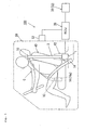
- the seat belt apparatus 100 of this embodiment is a seat belt apparatus for a vehicle to be installed in an automotive vehicle as "a vehicle with a seat belt apparatus" of the present invention.
- the seat belt apparatus 100 mainly comprises a seat belt retractor 1, a seat belt 3, a deflection fitting 10, a tongue 12, an outer anchor 14, a seat belt buckle 16, and an ECU 20.
- an input element 30 is installed in the vehicle to detect information about collision prediction or collision occurrence of the vehicle, information about the driving state of the vehicle, information about the sitting position and the body size of a vehicle occupant seated in a vehicle seat, information about traffic conditions around the vehicle, information about weather condition and about time zone, and the like and to input such detected information to the ECU 20.
- the detected information of the input element 30 is transmitted to the ECU 20 anytime or at predetermined intervals and is used for the operation control of the seat belt apparatus 100 and the like.
- the input element 30 of this embodiment includes a vehicle collision information detection sensor 32 for detecting information about a vehicle collision such as a prediction of a vehicle collision and an occurrence of actual vehicle collision.
- the vehicle collision information detection sensor 32 is a sensor capable of detecting (measuring) distance, speed, and acceleration of a collision object (a vehicle, obstacle, pedestrian, or the like) relative to the subject vehicle and also detecting (measuring) accelerations in three-axial (X-axis, Y-axis, and Z-axis) directions acting on the subject vehicle.
- the vehicle collision information detection sensor 32 may be composed of a single detection sensor or a combination of plural detection sensors. Specifically, millimeter wave radar, laser radar, acceleration sensor, and camera sensor may be used in the vehicle collision information detection sensor 32.
- a vehicle door sensor 52 mounted on the vehicle is adapted to detect the opening/closing state of a vehicle door 50.
- a contact sensor which comprises a first contact on the vehicle door side and a second contact on a vehicle pillar side and can detect the opening/closing of the vehicle door according to the contact between the first contact and the second contact may be employed as the vehicle door sensor 52.
- the vehicle door sensor 52 may be considered as a component of the seat belt retractor 1 or the seat belt apparatus 100.
- the information detected by the vehicle door sensor 52 is transmitted to the ECU 20 and is used for "retractor control processes A-C" as will be described later with regard to Figs. 3-5.
- the seat belt 3 is a long belt (webbing) to be used for restraining a vehicle occupant C (sometimes referred to as "driver") seated in a vehicle seat 40 as a driver's seat.
- the seat belt 3 corresponds to the "seat belt for occupant restraint" of the present invention.
- the seat belt 3 is withdrawn from the seat belt retractor 1 fixed relative to the vehicle and extends through a deflection fitting 10 provided around an area about the shoulder of the vehicle occupant C and is connected to an outer anchor 14 through a tongue 12.
- the deflection fitting 10 has a function of holding the seat belt 3 to the area about the shoulder of the occupant C and guiding the seat belt 3.
- the seat belt 3 becomes into the state worn by the vehicle occupant C.
- the tongue 12 corresponds to the "tongue” of the present invention and the seat belt buckle 16 to which the tongue 12 can be latched corresponds to the "seat belt buckle" of the present invention.
- the seat belt buckle 16 has a built-in buckle switch 16a.
- the buckle switch 16a detects that the tongue 12 is inserted into the seat belt buckle 16 so as to connect the seat belt to the seat belt buckle (actually, detects that the seat belt becomes into the worn state).
- the information detected by the buckle switch 16a is transmitted to the ECU 20 which determines whether or not the seat belt 3 is in the worn state.
- the buckle switch 16a corresponds to the "detection sensor for detecting that the tongue is latched to the seat belt buckle" of the present invention.
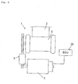
- the seat belt retractor 1 is a device capable of performing the action of winding or unwinding the seat belt 3 via a spool 5 and a motor 7 which will be described later and corresponds to the "seat belt retractor" of the present invention.
- the retractor 1 is installed in an accommodating space in a B-pillar 42 of the vehicle in the embodiment shown in Fig. 1.
- the ECU 20 has a function of conducting the control of the seat belt retractor 1 and other operational mechanisms based on the input signals from the input element 30 and comprises a CPU (Central processing unit), an input/output unit, a storage unit, a peripheral unit, and the like. Particularly in this embodiment, the ECU 20 controls the motor 7, which will be described later, of the seat belt retractor 1. Specifically, the ECU 20 controls the amount of current supplied to an electromagnetic coil of the motor 7 and the direction of the current supply so as to vary the rotational speed, the rotational direction, the rotational period of time, and the rotational torque (output) of a shaft of the motor 7.
- a CPU Central processing unit
- the ECU 20 controls the motor 7, which will be described later, of the seat belt retractor 1.
- the ECU 20 controls the amount of current supplied to an electromagnetic coil of the motor 7 and the direction of the current supply so as to vary the rotational speed, the rotational direction, the rotational period of time, and the rotational torque (output) of a shaft of the motor 7.
- the ECU 20 is structured as a means for controlling the driving of the motor 7 and controlling a power transmission mechanism 9, which will be described later, to switch between the state where the power of the motor 7 is transmitted to the spool 5 and the state where the power is not transmitted to the spool 5. The details will be described later. Further, the ECU 20 is also provided with a function of detecting (measuring) the current value of the motor 7 in operation.
- the ECU 20 corresponds to the "control means" of the present invention.
- the ECU 20 may be exclusive to the seat belt retractor 1 or used also for other control means for controlling driving system and/or electric system.
- the spool 5 as shown in Fig. 2 is formed in a columnar or cylindrical shape of which outer periphery (seat belt contact face) functions as the wind-up surface on which the seat belt 3 is wound.
- the spool 5 is a member for performing the winding action and unwinding action of the seat belt 3 for occupant restraint in association with the driving of the motor 7 as the "electric motor” of the present invention and corresponds to the "spool" of the present invention.
- the power transmission mechanism 9 is arranged between the spool 5 and the motor 7.
- the power transmission mechanism 9 is a mechanism capable of taking a connected state where the spool 5 and the motor 7 are connected (power transmission operation mode) and a disconnected state where the connected state is cancelled (power transmission disconnection mode).
- the power transmission mechanism 9 is sometimes referred to as so-called "clutch" which comprises a combination of gears.
- the connected state of the power transmission mechanism 9 is a state where the power of the motor 7 is allowed to be transmitted to the spool via the power transmission mechanism 9. When the motor 7 is driven in this connected state, the power of the motor 7 is transmitted to the spool 5 via the power transmission mechanism 9. During this, the rotational speed of the motor 7 is reduced by the power transmission mechanism 9.
- the spool 5 and the motor 7 may be directly connected without the power transmission mechanism 9 disposed between the spool 5 and the motor 7, if required.
- the power transmission mechanism 9 is constructed as a so-called “single-stage clutch", but not illustrated. Accordingly, when the motor 7 is driven with a predetermined motor output in the power transmission operation mode of the power transmission mechanism 9, the rotation of the motor 7 is transmitted to the spool 5 with the rotational speed being reduced so that the spool 5 is driven to rotate with predetermined torque at predetermined rotational speed.
- a power transmission mechanism capable of changing the rotational torque and the rotational speed of the spool into several stages may be employed.
- the power transmission mechanism can be set in a high-reduction ratio mode with relatively high rotational torque and relatively low rotational speed in order to respond to a need for winding of the seat belt onto the spool with large belt tension.
- the power transmission mechanism can be set in a low-reduction ratio mode with relatively low rotational torque and relatively high rotational speed in order to respond to a need for rapid winding of the seat belt onto the spool.
- the seat belt retractor 1 of this embodiment has the following seven seat belt control modes of the seat belt 3. Based on these seat belt control modes, the control of the motor 7 and the power transmission mechanism 9 are performed by the ECU 20.
- Belt storage mode is a control mode in which the seat belt 3 is not used and fully wound onto the spool 5.
- the motor 7 is not driven and the power transmission mechanism 9 is set to the power transmission disconnection mode. Therefore, only very weak belt tension is applied to the seat belt 3 and the power consumption is zero.
- Belt withdrawing mode is a control mode in which the seat belt 3 is withdrawn from the spool 5 so as to be worn by the occupant.
- the seat belt retractor 1 in the belt withdrawing mode is also set in the power transmission disconnection mode. Therefore, the seat belt 3 can be withdrawn with small force. Also in this case, the motor 7 is not driven so that the power consumption is zero.
- Belt winding and fitting mode is a control mode in which after the seat belt 3 is withdrawn and the tongue (the tongue 12 in Fig. 1) is inserted into and latched with the seat belt buckle to turn ON the buckle switch (the buckle switch 16a in Fig. 1), excessively withdrawn part of the seat belt 3 is wound in order to fit the seat belt 3 to the occupant.
- the belt winding and fitting mode is a control mode in which when the occupant moves so as to withdraw a predetermined amount of the seat belt 3 from the normally used state of the seat belt 3 (at this point, the buckle switch is in the ON state) and then the occupant returns to the original position, the withdrawn part of the seat belt 3 is wound.
- the motor 7 In the seat belt retractor 1 in the belt winding and fitting mode, the motor 7 is driven to rotate at high rotational speed in the belt winding direction and the power transmission mechanism 9 is set to the power transmission operation mode. Therefore, the seat belt 3 is rapidly wound onto the spool 5 and then the motor 7 is stopped when very small predetermined belt tension is generated, whereby the seat belt 3 is worn by and fitted to the occupant.
- Normal wearing mode is a control mode in which the occupant wears the seat belt 3 in the normal state after the belt winding and fitting mode is terminated.
- the motor 7 is not driven and the power transmission mechanism 9 is set in the power transmission disconnection mode. Therefore, only very weak belt tension is applied to the seat belt 3 so that the vehicle occupant can wear the seat belt 3 without any stress.
- the power consumption is zero.
- Warning mode is a control mode in which when dozing of the driver or an obstacle around the subject vehicle is detected with the seat belt being in the normal wearing mode during running, the seat belt 3 is wound repeatedly predetermined times so as to warn the driver.
- the motor 7 In the seat belt retractor 1 in the warning mode, the motor 7 is controlled to be driven repeatedly. Therefore, the operation of applying relatively strong belt tension (but which is weaker than that of the belt tension during the emergency mode as will be described later) and very weak belt tension onto the seat belt 3 is alternately repeated, thereby drawing the driver's attention to the dozing and the obstacle around the vehicle.
- Emergency mode is a control mode which is set when the vehicle extremely likely have a collision with an obstacle or the like during running in the normal wearing mode or following the aforementioned warning mode.
- the power transmission mechanism 9 is set in the power transmission operation mode and the motor 7 is controlled to rotate at high rotational speed with high rotational torque in the belt winding direction. Therefore, the motor 7 is stopped when predetermined extremely strong belt tension is generated on the seat belt 3 after the seat belt 3 is rapidly wound onto the spool 5, thereby securely restraining the vehicle occupant with the seat belt 3.
- Belt winding and storing mode is a control mode in which the seat belt 3 is fully wound to be in the storage state.
- the power transmission mechanism 9 is set to the power transmission operation mode and the motor 7 is controlled to rotate in the belt winding direction. Accordingly, the withdrawn seat belt 3 is promptly wound onto the spool 5.
- the motor 7 is stopped when the seat belt 3 is fully wound and a predetermined belt tension which is very weak is developed, whereby the seat belt 3 becomes to the belt storage mode in which the aforementioned very weak belt tension is applied to the seat belt 3.
- the behavior of the vehicle door 50 as an object which catches the seat belt 3 or the tongue 12 is reflected at least in control for the seat belt winding action so as to achieve rational sophisticated control.
- the control in the belt winding and storing mode according to this embodiment is based on the premise that the original purpose of the seat belt winding action (seat belt storing control) is to prevent the seat belt 3 which is kept in the unwound state or the tongue 12 from being caught by the vehicle door 50.
- This control is conducted according to, for example, "retractor control process (seat belt storing control process)" as shown in Fig. 3 through Fig. 5 by the control means (the ECU 20 in Fig. 1 and Fig. 2).
- Fig. 3 is a flow chart of the retractor control process A according to this embodiment.
- step S10 it is determined whether or not the seat belt (the seat belt 3 in Fig. 1) is changed from the worn state to the released state. Specifically, based on the information detected by the buckle switch 16a for detecting the insertion and latching of the tongue 12 to the seat belt buckle 16, it is determined that the seat belt 3 is changed from the worn state to the released state when the buckle switch 16a is changed from ON state to OFF state. This determination is achieved by the ECU 20 which detects the information from the buckle switch 16a. In the step S 10, the process continues until the seat belt 3 is changed from the worn state to the released state and proceeds to step S12 when it is determined that the seat belt 3 is changed from the worn state to the released state (YES in step S10).
- step S12 it is determined whether or not the vehicle door (the vehicle door 50 shown in Fig. 1) is in the open state. Specifically, based on the information detected by the vehicle door sensor 52 shown in Fig. 1, it is determined that the vehicle door 50 is in the open state when the vehicle door sensor is ON. This determination is achieved by the ECU 20 which detects the information from the vehicle door sensor 52. In the step 12, the process proceeds to step S14 when it is determined that the vehicle door 50 is in the open state (YES in step S12) and proceeds to step S16 if not, i.e. when it is determined that the vehicle door 50 is in the closed state (NO in step S12).
- step S 14 the seat belt winding control (seat belt storing control) with the motor 7 in the high power output control (motor output P1) is conducted.
- step S16 the seat belt winding control (seat belt storing control) with the motor 7 in the low power output control (motor output P2 ⁇ P1) is conducted.
- step S 14 the control in which the motor output of the motor 7 is set to the motor output P1 is conducted in step S 14 in order to rapidly wind up the seat belt 3.
- the control in which the motor output of the motor 7 is set to the motor output P2 is conducted in step S16 in order to gently wind up the seat belt 3 for the vehicle occupant C. That is, the control in step S14 and the control in step S16 are different from each other in the motor output of the motor 7.
- step S 14 and step S16 the power transmission mechanism 9 of the seat belt retractor 1 is set in the power transmission operation mode and the motor 7 is driven to rotate in the belt winding direction. Since the motor output of the motor 7 is the product of current value (sometimes referred to as “control current value”) and voltage value (sometimes referred to as “applied voltage value”), the motor output can be changed by suitably changing the current value and/or the voltage value.
- control current value sometimes referred to as "control current value”
- voltage value sometimes referred to as "applied voltage value
- the seat belt winding action in the belt winding and storing mode may be conducted only by the driving force of the motor 7 or by the winding force of an elastic member such as a return spring which acts on the spool 5 and the driving force of the motor 7 as secondary force.
- retractor control process A rational sophisticated (detailed) control for the seat belt winding action is achieved by changing the motor output of the motor 7 according to the state of the vehicle door 50 when the wearing of the seat belt 3 is cancelled (satisfaction pattern of starting condition) in the seat belt storing control.
- the retractor control process A corresponds to "control mode" described in claim 3 through claim 7.
- Fig. 4 is a flow chart of the retractor control process B according to this embodiment.
- step S20 it is determined whether or not the vehicle door (the vehicle door 50 in Fig. 1) is changed from the closed state to the open state. Specifically, based on the information detected by the vehicle door sensor 52 shown in Fig. 1, it is determined that the vehicle door 50 is changed from the closed state to the open state when the vehicle door sensor 52 is changed from OFF state to ON state. This determination is achieved by the ECU 20 which detects the detected information from the vehicle door sensor 52.
- the process continues until the vehicle door 50 is changed from the closed state to the open state and proceeds to step S22 when it is determined that the vehicle door 50 is changed from the closed state to the open state (YES in step S20).
- step S22 it is determined whether or not the seat belt (the seat belt 3 in Fig. 1) is changed from the worn state to the released state. Specifically, based on the information detected by the buckle switch 16a for detecting the insertion and latching of the tongue 12 to the seat belt buckle 16 shown in Fig. 1, it is determined that the seat belt 3 is in the worn state when the buckle switch 16a is in ON state. This determination is achieved by the ECU 20 which detects the information from the buckle switch 16a. In the step S22, the process proceeds to step S24 when it is determined that the seat belt 3 is in the released state (NO in step S22) and proceeds to step S26 when it is determined that the seat belt 3 is in the worn state (YES in step S22).
- step S24 the seat belt winding control (seat belt storing control) with the motor 7 in the low power output control (motor output P3) is conducted.
- step S26 the seat belt winding control (seat belt storing control) by the motor 7 is not conducted. (The motor output is zero.) It should be noted that, even in step S26, the motor output of the motor 7 may be set to such a degree that the spool 5 is not rotated.
- step S24 the control in which the motor output of the motor 7 is set to the motor output P3 is conducted in step S24 in order to gently wind up the seat belt 3 for the vehicle occupant C.
- the motor output P3 can be suitably set to any degree within a range under a preset reference value.
- the seat belt winding action is not required in step S26. That is, the control in step S24 and the control in step S26 are different from each other in the motor output of the motor 7.
- step S24 the power transmission mechanism 9 of the seat belt retractor 1 is set in the power transmission operation mode and the motor 7 is driven with the motor output P3 to rotate in the belt winding direction.
- step S26 the power transmission mechanism 9 of the seat belt retractor 1 is set in the power transmission operation mode and the motor output of the motor 7 is set to zero or the power transmission mechanism 9 of the seat belt retractor 1 is set to the power transmission disconnection mode.
- retractor control process B rational sophisticated (detailed) control for the seat belt winding action is achieved by changing the motor output of the motor 7 according to the state of the seat belt 3 when the vehicle door 50 is changed from the closed state to the open state (satisfaction pattern of starting condition) in the seat belt storing control.
- the retractor control process B corresponds to "control mode" described in claim 4 through claim 8.
- Fig. 5 is a flow chart of the retractor control process C according to this embodiment.
- step S30 and step 32 are similar to step S10 and step S12 of the aforementioned retractor control A.
- step S34 the process proceeds to step S34. If not, i.e. when it is determined that the vehicle door 50 is in the closed state (NO in step S32), the process proceeds to step S36.
- step S34 the seat belt winding control (seat belt storing control) with the motor 7 in the high power output control (motor output P4) is conducted.
- step S36 the seat belt winding control (seat belt storing control) by the motor 7 is not conducted. (The motor output is zero.) It should be noted that, even in step S36, the motor output of the motor 7 may be set to such a degree that the spool 5 is not rotated.
- step S34 the control in which the motor output of the motor 7 is set to the high motor output P4 is conducted in step S34 in order to rapidly wind up the seat belt 3.
- the motor output P4 can be suitably set to any degree within a range over a preset reference value.
- the control in step S34 and the control in step S36 are different from each other in the motor output of the motor 7.
- step S34 the power transmission mechanism 9 of the seat belt retractor 1 is set in the power transmission operation mode and the motor 7 is driven with the motor output P4 to rotate in the belt winding direction.
- step S36 the power transmission mechanism 9 of the seat belt retractor 1 is set in the power transmission operation mode and the motor output of the motor 7 is set to zero or the power transmission mechanism 9 of the seat belt retractor 1 is set to the power transmission disconnection mode.
- retractor control process C rational sophisticated (detailed) control for the seat belt winding action is achieved by changing the motor output of the motor 7 according to the state of the vehicle door 50 when the wearing of the seat belt 3 is cancelled (satisfaction pattern of starting condition) in the seat belt storing control.
- the retractor control process C corresponds to "control mode" described in claim 3 through claim 7.
- the present invention provides a seat belt retractor 1, a seat belt apparatus 100, and a vehicle with the seat belt apparatus 100 in which rational control for the seat belt winding action is achieved.
- the aforementioned retractor control processes A through C may be employed independently.
- a first combination of the aforementioned retractor control process A and the aforementioned retractor control process B or a second combination of the aforementioned retractor control process B and the aforementioned retractor control process C may be employed.
- the motor output P2 in step S 16 and the motor output P3 in step S24 are set to be equal to each other.
- the motor 7 when starting condition which is defined by the state of the seat belt 3 relative to the vehicle occupant C and the state of the vehicle door 50 corresponding to the seat belt 3 is satisfied, the motor 7 is controlled to rotate in the seat belt winding direction such that the motor output of the motor 7 is varied according to the satisfaction pattern of the starting condition. That is, the start of winding of the seat belt 3 depends on the combination of the state of the seat belt 3 (the worn state or the released state) and the state of the vehicle door 50 (the open state or the closed state) and the motor output of the motor 7 is varied according to the satisfaction pattern of the starting condition. Satisfaction patterns of the starting condition may be suitably set according to the combination of the state of the seat belt 3 and the state of the vehicle door 50 and the satisfying order. The number of the satisfaction patterns can be set according to need.
- the seat belt retractor of the present invention can be adopted to seat belt apparatuses to be installed in a vehicle for transfer of occupant(s) such as automobile, aircraft, boat, train, and bus.
Landscapes
- Engineering & Computer Science (AREA)
- Mechanical Engineering (AREA)
- Automotive Seat Belt Assembly (AREA)
Abstract
Description
- The present invention relates to a technology for developing a seat belt retractor to be installed in a vehicle.
- Conventionally, a seat belt apparatus is known, which is structured to protect an occupant in a vehicle by a seat belt (webbing) restraining the occupant. For example,
Japanese translation of PCT international application No. 2003-507252 - The technology described in
Patent Document 1 proposes a possibility of using an electric motor to conduct the seat belt winding action of the spool, as a structure of the seat belt retractor. When this structure is used for control (seat belt storing control) of winding up the seat belt in order to prevent the seat belt from being kept in the unwound state, it is desired to reasonably control the seat belt winding action by the electric motor.
Specifically, the original purpose of the seat belt storing control is to prevent a seat belt which is kept in the unwound state or a tongue attached to the seat belt from being caught by a vehicle door. If, in addition, the behavior of the vehicle door as an object which catches the seat belt or the tongue is reflected at least in control for the seat belt winding action, rational sophisticated (detailed) control is enabled. The inventor of the present invention focused attention on the behavior of the vehicle door during the seat belt winding control and came up with a structure capable of changing the mode of the seat belt winding action based on the behavior of the vehicle door.
It is an object of the present invention to provide a technology of a seat belt retractor to be installed in a vehicle which relates to the seat belt winding action using an electric motor for preventing a seat belt from being kept in the unwound state and which is effective for rationalizing the seat belt winding action. - For achieving the object, the present invention is made. The present invention can be typically adopted to a seat belt retractor to be installed in an automobile. In addition, the present invention can be adopted to a technology for developing a seat belt retractor to be installed in a vehicle other than the automobile, such as aircraft, boat, train, and bus.
- The first aspect of the present invention for achieving the aforementioned object is a seat belt retractor claimed in
claim 1.
The seat belt retractor claimed inclaim 1 is a device to be installed in a vehicle and comprises at least an electric motor, a spool, and a control means. - The spool of this invention is a member which is operated in association with the driving of the electric motor to wind or unwind a seat belt for occupant restraint. The seat belt capable of being wound onto and unwound from the spool is a long belt to be worn by a vehicle occupant seated in a seat and is sometimes called "webbing". Typically, the vehicle occupant seated in the vehicle seat is restrained by the seat belt when restraint is required such as a vehicle collision. In the present invention, if required, a power transmission mechanism may be suitably disposed between the electric motor and the spool to selectively achieve a connected state where the electric motor and the spool are connected and a disconnected state where the connected state is cancelled. Also in the present invention, the seat belt winding action by the spool may be conducted only by the driving force of the electric motor or by the winding force of an elastic member such as a return spring which acts on the spool and the driving force of the electric motor as secondary force.
- The control means of the present invention is adapted at least as a means for controlling the driving of the electric motor and controls the driving direction, the driving time, and the output of the electric motor. The control means typically comprises a CPU (central processing unit), an input/output unit, a storage unit, a peripheral unit, and the like. The control means may be provided exclusively for the seat belt retractor or used also for other control means for controlling driving system and/or electric system.
- Specifically, in cases that starting condition which is defined by the state of the seat belt relative to a vehicle occupant and the state of a vehicle door corresponding to the seat belt is satisfied, the control means of the present invention controls the electric motor to rotate in the belt winding direction such that the motor output of the electric motor is varied according to the satisfaction pattern of the starting condition. That is, in the present invention, the start of the winding of the seat belt depends on the combination of the state of the seat belt (the worn state or the released state) and the state of the vehicle door (the open state or the closed state). The motor output of the electric motor is varied according to the satisfaction pattern of the starting condition. The satisfaction patterns of the starting condition may be suitably set according to the combination of the state of the seat belt and the state of the vehicle door and the satisfying order. The number of the satisfaction patterns can be set according to need. Because the motor output of the electric motor is the product of current value (sometimes referred to as "control current value") and voltage value (sometimes referred to as "applied voltage value"), the motor output can be changed by suitably changing the current value and/or the voltage value.
- According to the invention claimed in
claim 1 with regard to the seat belt storing control by the seat belt retractor, the electric motor is used to conduct the seat belt winding action so as to reflect the state of the seat belt and the behavior of the vehicle door into the control for the seat belt winding action as well as prevent the seat belt from being kept in the unwound state. Therefore, the present invention provides a seat belt retractor capable of providing rational sophisticated (detailed) control with regard to seat belt winding action using the electric motor. - The second aspect of the present invention for achieving the aforementioned object is a seat belt retractor as claimed in claim 2.
In the seat belt retractor claimed in claim 2, in cases that the wearing of the seat belt on the vehicle occupant is cancelled, the control means claimed inclaim 1 controls the electric motor to rotate in the belt winding direction such that the motor output of the electric motor is varied according to the state of the vehicle door corresponding to the seat belt. - By the way, if a seat belt is kept in a state withdrawn from a spool in a seat belt retractor of this kind, there is a risk of occurrence of such a trouble that the seat belt itself or a tongue attached to the seat belt is caught by the vehicle door. In order to prevent such a trouble, the seat belt retractor is desired to have such a structure as to conduct the seat belt winding action (seat belt storing action) for actively winding a withdrawn seat belt onto a spool using an electric motor. In addition, by reflecting the behavior of the vehicle door as an object catching the seat belt into the control for the seat belt winding action, rational sophisticated (detailed) control is enabled.
According to the present invention, in cases where the wearing of the seat belt on the vehicle occupant is cancelled, the electric motor is controlled to rotate in the belt winding direction such that the motor output of the electric motor is varied based on the state of the vehicle door corresponding to the seat belt (satisfaction pattern of the starting condition). Timing for driving the electric motor to rotate in the belt winding direction may be at a time when the wearing of the seat belt is cancelled or a time when it is detected that the wearing of the seat belt is already cancelled. - The present invention is based on the premise that the original purpose of the seat belt winding action (seat belt storing control) is to prevent the seat belt which is kept in the unwound state or the tongue attached to the seat belt from being caught by the vehicle door so that the reflection of the behavior of the vehicle door as a direct object of catching the seat belt and the tongue is effective for rational sophisticated control. In this case, the speed and time until the seat belt winding action by the electric motor is completed can be set based on the degree of time until the vehicle door is closed.
- Specifically, when there is long time until the vehicle door is closed, the control in which the motor output of the electric motor is set to relatively small output or the electric motor is not driven can be conducted in order to gently wind up the seat belt for the vehicle occupant. On the other hand, when there is short time until the vehicle door is closed, the control in which the motor output of the electric motor is set to relatively large output is needed in order to rapidly wind up the seat belt. The electric motor is controlled to rotate in the belt winding direction, thereby preventing the seat belt from being kept in the unwound state.
- Accordingly, the invention claimed in claim 2 relates to the seat belt storing control by the seat belt retractor and enables rational sophisticated control with regard to the seat belt winding action.
- The third aspect of the present invention for achieving the aforementioned object is a seat belt retractor claimed in
claim 3.
In the seat belt retractor claimed inclaim 3, the control means claimed inclaim 1 or 2 controls the electric motor to rotate in the belt winding direction with a first motor output in cases where the vehicle door corresponding to the seat belt is in the closed state when the wearing of said seat belt is cancelled. On the other hand, the control means of this invention controls the electric motor to rotate in the belt winding direction with a second motor output larger than said first motor output in cases where the vehicle door corresponding to the seat belt is in the open state when the wearing of the seat belt is cancelled. In cases where the vehicle door is in closed state when the wearing of the seat belt is cancelled, there must be relatively long time until the vehicle door is closed again once it is opened. Therefore, in this case, the control in which the motor output of the motor is set to a relatively small output or the electric motor is not driven can be conducted in order to gently wind up the seat belt for the vehicle occupant. On the other hand, in case of the vehicle door is already in the open state when the wearing of the seat belt is cancelled, there must be short time until the vehicle door is closed. Therefore, in this case, the control in which the motor output of the electric motor is set to relatively large output is needed in order to rapidly wind up the seat belt. - Accordingly, the invention claimed in
claim 3 relates to the seat belt storing control by the seat belt retractor and has a structure capable of varying the motor output according to the state of the vehicle door when the wearing of the seat belt is cancelled, thereby enabling rational sophisticated control with regard to the seat belt winding action.
In the present invention, the first motor output and the second motor output are set such that the second motor output is larger than the first motor output. The first motor output may be set to a predetermined value lower than that of the second motor output (including such a motor output that the spool is not rotated) or zero (the motor does not output). - The fourth aspect of the present invention for achieving the aforementioned object is a seat belt retractor claimed in claim 4.
In the seat belt retractor claimed in claim 4, the control means claimed in any one ofclaims 1 through 3 controls the electric motor to rotate in the belt winding direction in cases where the wearing of the seat belt is cancelled when the vehicle door corresponding to the seat belt is changed from the closed state to the open state. On the other hand, the control means controls the electric motor not to rotate in cases where the seat belt is worn when the vehicle door corresponding to the seat belt is changed from the closed state to the open state. That is, in cases where the wearing of the seat belt is cancelled immediately after the vehicle door is opened, it is more likely that the vehicle door will not be closed for a while. Therefore, in this case, the control in which the motor output of the motor is set to a relatively low output can be conducted in order to gently wind up the seat belt for the vehicle occupant. On the other hand, in cases where the seat belt is in the worn state, the seat belt winding action is not required. - Accordingly, the invention claimed in claim 4 relates to the seat belt storing control by the seat belt retractor and has a structure capable of varying the motor output according to the state of the seat belt when the vehicle door is changed from the closed state to the open state, thereby enabling rational sophisticated control with regard to the seat belt winding action.
- The fifth aspect of the present invention for achieving the aforementioned object is a seat belt apparatus as claimed in
claim 5.
The seat belt apparatus claimed inclaim 5 is an apparatus to be installed in a vehicle and comprises at least a seat belt for occupant restraint, an electric motor, a spool, a control means, a seat belt buckle, a tongue, and a detection sensor.
The seat belt of the present invention is a long belt to be worn by a vehicle occupant seated in a seat and is sometimes called "webbing". Typically, the vehicle occupant seated in the vehicle seat is restrained by the seat belt when restraint is required such as a vehicle collision. The seat belt buckle of the present invention is a member fixed to a vehicle body. The tongue of the present invention is a member which is attached to the seat belt and is latched to the buckle when the seat belt is worn by the vehicle occupant. The detection sensor of the present invention is a means for detecting that the tongue is latched to the buckle.
The control means of the present invention determines whether or not the seat belt is worn by a vehicle occupant based on information detected by the detection sensor. In cases where starting condition which is defined by the state of the seat belt relative to the vehicle occupant and the state of a vehicle door corresponding to the seat belt is satisfied, the control means controls the electric motor to rotate in the belt winding direction such that the motor output of the electric motor is varied according to the satisfaction pattern of the starting condition.
The electric motor and the spool of this invention have substantially the same functions as those of the seat belt retractor claimed inclaim 1. - Accordingly, the invention claimed in
claim 5 relates to the seat belt storing control by the seat belt apparatus and can prevent the seat belt from being kept in the unwound state by using the electric motor for the belt winding action and can reflect the state of the seat belt and the behavior of the vehicle door into the control for the seat belt winding action. Accordingly, the invention provides a seat belt retractor capable of conducting rational sophisticated (detailed) control with regard to the seat belt winding action using the electric motor. - The sixth aspect of the present invention for achieving the aforementioned object is a seat belt apparatus as claimed in claim 6.
In the seat belt apparatus claimed in claim 6, in cases where the wearing of the seat belt is cancelled, the control means claimed inclaim 5 controls the electric motor to rotate in the belt winding direction such that the motor output of the electric motor is varied according to the state of the vehicle door corresponding to the seat belt. - Accordingly, the invention claimed in claim 6 has substantially the same works and effects as those of the invention claimed in claim 2. This invention relates to the seat belt storing control by the seat belt apparatus and enables rational sophisticated control with regard to the seat belt winding action.
- The seventh aspect of the present invention for achieving the aforementioned object is a seat belt apparatus as claimed in claim 7.
In the seat belt apparatus claimed in claim 7, the control means claimed inclaim 5 or 6 controls the electric motor to rotate in the belt winding direction with a first motor output in cases where the vehicle door corresponding to the seat belt is in the closed state when it is determined that the wearing of the seat belt is cancelled based on the information detected by the detection sensor. On the other hand, the control means controls the electric motor to rotate in the belt winding direction with a second motor output larger than the first motor output in cases where the vehicle door corresponding to the seat belt is in the open state when it is determined that the wearing of the seat belt is cancelled based on the information detected by the detection sensor. - Therefore, the invention claimed in claim 7 has substantially the same works and effects as those of the invention claimed in
claim 3. This invention relates to the seat belt storing control by the seat belt apparatus and enables rational sophisticated control with regard to the seat belt winding action. - The eighth aspect of the present invention for achieving the aforementioned object is a seat belt apparatus as claimed in claim 8.
In the seat belt apparatus claimed in claim 8, the control means claimed in any one ofclaims 5 through 7 controls the electric motor to rotate in the belt winding direction in cases where it is determined that the wearing of said seat belt is cancelled based on the information detected by said detection sensor when the vehicle door corresponding to the seat belt is changed from the closed state to the open state. On the other hand, the control means controls said electric motor not to rotate in cases where it is determined that the seat belt is worn based on the information detected by said detection sensor. - Accordingly, the invention claimed in claim 8 has substantially the same works and effects as those of the invention claimed in claim 4. This invention relates to the seat belt storing control by the seat belt apparatus and enables rational sophisticated control with regard to the seat belt winding action.
- The ninth aspect of the present invention for achieving the aforementioned object is a vehicle with a seat belt apparatus claimed in claim 9.
The vehicle with a seat belt apparatus claimed in claim 9 comprises at least a seat belt apparatus as claimed in any one ofclaims 5 through 8. In the vehicle of the present invention, the seat belt apparatus is accommodated in an accommodating space in the vehicle such as an accommodating space in a pillar, an accommodating space in a seat, or an accommodating space in another part of the vehicle. - Accordingly, the invention claimed in claim 9 provides a vehicle comprising a seat belt apparatus which uses an electric motor for the seat belt winding action so as not only to prevent the seat belt from being kept in the unwound state but also to reflect the behavior of a vehicle door into the control for the seat belt winding action, wherein the seat belt apparatus is accommodated in an accommodating space in the vehicle.
- As described in the above, the present invention relates to a structure of a seat belt retractor in which a spool operates in association with the driving of an electric motor to wind and unwind a seat belt for occupant restraint and provides such control as to enable rationalization of the seat belt winding action. That is, in cases where starting condition which is defined by the state of the seat belt relative to the vehicle occupant and the state of a vehicle door corresponding to the seat belt is satisfied, an electric motor is controlled to rotate in the belt winding direction such that the motor output of the electric motor is varied according to the satisfaction pattern of the starting condition, thereby enabling the rationalization of the seat belt action.
- Hereinafter, embodiments of the present invention will be described in detail with reference to drawings.
- Fig. 1 is an illustration showing the structure of a
seat belt apparatus 100 as an embodiment of "the seat belt apparatus" according to the present invention; - Fig. 2 is an illustration showing the schematic structure of a
seat belt retractor 1 shown in Fig. 1; - Fig. 3 is a flow chart showing the retractor control process A according to the embodiment;
- Fig. 4 is a flow chart showing the retractor control process B according to the embodiment; and
- Fig. 5 is a flow chart showing the retractor control process C according to the embodiment.
- As shown in Fig. 1, the
seat belt apparatus 100 of this embodiment is a seat belt apparatus for a vehicle to be installed in an automotive vehicle as "a vehicle with a seat belt apparatus" of the present invention. theseat belt apparatus 100 mainly comprises aseat belt retractor 1, aseat belt 3, a deflection fitting 10, atongue 12, anouter anchor 14, aseat belt buckle 16, and anECU 20. In addition, aninput element 30 is installed in the vehicle to detect information about collision prediction or collision occurrence of the vehicle, information about the driving state of the vehicle, information about the sitting position and the body size of a vehicle occupant seated in a vehicle seat, information about traffic conditions around the vehicle, information about weather condition and about time zone, and the like and to input such detected information to theECU 20. The detected information of theinput element 30 is transmitted to theECU 20 anytime or at predetermined intervals and is used for the operation control of theseat belt apparatus 100 and the like. - The
input element 30 of this embodiment includes a vehicle collisioninformation detection sensor 32 for detecting information about a vehicle collision such as a prediction of a vehicle collision and an occurrence of actual vehicle collision. The vehicle collisioninformation detection sensor 32 is a sensor capable of detecting (measuring) distance, speed, and acceleration of a collision object (a vehicle, obstacle, pedestrian, or the like) relative to the subject vehicle and also detecting (measuring) accelerations in three-axial (X-axis, Y-axis, and Z-axis) directions acting on the subject vehicle. The vehicle collisioninformation detection sensor 32 may be composed of a single detection sensor or a combination of plural detection sensors. Specifically, millimeter wave radar, laser radar, acceleration sensor, and camera sensor may be used in the vehicle collisioninformation detection sensor 32. - In this embodiment, a
vehicle door sensor 52 mounted on the vehicle is adapted to detect the opening/closing state of avehicle door 50. For example, a contact sensor which comprises a first contact on the vehicle door side and a second contact on a vehicle pillar side and can detect the opening/closing of the vehicle door according to the contact between the first contact and the second contact may be employed as thevehicle door sensor 52. Thevehicle door sensor 52 may be considered as a component of theseat belt retractor 1 or theseat belt apparatus 100. The information detected by thevehicle door sensor 52 is transmitted to theECU 20 and is used for "retractor control processes A-C" as will be described later with regard to Figs. 3-5. - The
seat belt 3 is a long belt (webbing) to be used for restraining a vehicle occupant C (sometimes referred to as "driver") seated in avehicle seat 40 as a driver's seat. Theseat belt 3 corresponds to the "seat belt for occupant restraint" of the present invention. Theseat belt 3 is withdrawn from theseat belt retractor 1 fixed relative to the vehicle and extends through a deflection fitting 10 provided around an area about the shoulder of the vehicle occupant C and is connected to anouter anchor 14 through atongue 12. The deflection fitting 10 has a function of holding theseat belt 3 to the area about the shoulder of the occupant C and guiding theseat belt 3. By inserting thetongue 12 to aseat belt buckle 16 fixed to the vehicle body, theseat belt 3 becomes into the state worn by the vehicle occupant C. Thetongue 12 corresponds to the "tongue" of the present invention and theseat belt buckle 16 to which thetongue 12 can be latched corresponds to the "seat belt buckle" of the present invention. - The
seat belt buckle 16 has a built-inbuckle switch 16a. Thebuckle switch 16a detects that thetongue 12 is inserted into theseat belt buckle 16 so as to connect the seat belt to the seat belt buckle (actually, detects that the seat belt becomes into the worn state). The information detected by thebuckle switch 16a is transmitted to theECU 20 which determines whether or not theseat belt 3 is in the worn state. Thebuckle switch 16a corresponds to the "detection sensor for detecting that the tongue is latched to the seat belt buckle" of the present invention. - The
seat belt retractor 1 is a device capable of performing the action of winding or unwinding theseat belt 3 via aspool 5 and a motor 7 which will be described later and corresponds to the "seat belt retractor" of the present invention. Theretractor 1 is installed in an accommodating space in a B-pillar 42 of the vehicle in the embodiment shown in Fig. 1. - The
ECU 20 has a function of conducting the control of theseat belt retractor 1 and other operational mechanisms based on the input signals from theinput element 30 and comprises a CPU (Central processing unit), an input/output unit, a storage unit, a peripheral unit, and the like. Particularly in this embodiment, theECU 20 controls the motor 7, which will be described later, of theseat belt retractor 1. Specifically, theECU 20 controls the amount of current supplied to an electromagnetic coil of the motor 7 and the direction of the current supply so as to vary the rotational speed, the rotational direction, the rotational period of time, and the rotational torque (output) of a shaft of the motor 7. TheECU 20 is structured as a means for controlling the driving of the motor 7 and controlling a power transmission mechanism 9, which will be described later, to switch between the state where the power of the motor 7 is transmitted to thespool 5 and the state where the power is not transmitted to thespool 5. The details will be described later. Further, theECU 20 is also provided with a function of detecting (measuring) the current value of the motor 7 in operation. TheECU 20 corresponds to the "control means" of the present invention.
TheECU 20 may be exclusive to theseat belt retractor 1 or used also for other control means for controlling driving system and/or electric system. - The
spool 5 as shown in Fig. 2 is formed in a columnar or cylindrical shape of which outer periphery (seat belt contact face) functions as the wind-up surface on which theseat belt 3 is wound. Thespool 5 is a member for performing the winding action and unwinding action of theseat belt 3 for occupant restraint in association with the driving of the motor 7 as the "electric motor" of the present invention and corresponds to the "spool" of the present invention. - In this embodiment, the power transmission mechanism 9 is arranged between the
spool 5 and the motor 7. The power transmission mechanism 9 is a mechanism capable of taking a connected state where thespool 5 and the motor 7 are connected (power transmission operation mode) and a disconnected state where the connected state is cancelled (power transmission disconnection mode). The power transmission mechanism 9 is sometimes referred to as so-called "clutch" which comprises a combination of gears. The connected state of the power transmission mechanism 9 is a state where the power of the motor 7 is allowed to be transmitted to the spool via the power transmission mechanism 9. When the motor 7 is driven in this connected state, the power of the motor 7 is transmitted to thespool 5 via the power transmission mechanism 9. During this, the rotational speed of the motor 7 is reduced by the power transmission mechanism 9. On the other hand, in the disconnected state of the power transmission mechanism 9, the physical connection between thespool 5 and the motor 7 is cancelled so as to allow the easy unwinding (withdrawing) of theseat belt 3 from thespool 5. It should be noted that thespool 5 and the motor 7 may be directly connected without the power transmission mechanism 9 disposed between thespool 5 and the motor 7, if required. - In this embodiment, the power transmission mechanism 9 is constructed as a so-called "single-stage clutch", but not illustrated. Accordingly, when the motor 7 is driven with a predetermined motor output in the power transmission operation mode of the power transmission mechanism 9, the rotation of the motor 7 is transmitted to the
spool 5 with the rotational speed being reduced so that thespool 5 is driven to rotate with predetermined torque at predetermined rotational speed.
Instead of the power transmission mechanism 9, a power transmission mechanism capable of changing the rotational torque and the rotational speed of the spool into several stages may be employed. For example, in case of a two-stage clutch capable of changing the rotational torque and the rotational speed of the spool into two stages, the power transmission mechanism can be set in a high-reduction ratio mode with relatively high rotational torque and relatively low rotational speed in order to respond to a need for winding of the seat belt onto the spool with large belt tension. On the other hand, the power transmission mechanism can be set in a low-reduction ratio mode with relatively low rotational torque and relatively high rotational speed in order to respond to a need for rapid winding of the seat belt onto the spool. - In this embodiment, the
seat belt retractor 1 of this embodiment has the following seven seat belt control modes of theseat belt 3. Based on these seat belt control modes, the control of the motor 7 and the power transmission mechanism 9 are performed by theECU 20. - Belt storage mode is a control mode in which the
seat belt 3 is not used and fully wound onto thespool 5. In theseat belt retractor 1 in the belt storage mode, the motor 7 is not driven and the power transmission mechanism 9 is set to the power transmission disconnection mode. Therefore, only very weak belt tension is applied to theseat belt 3 and the power consumption is zero.] - Belt withdrawing mode is a control mode in which the
seat belt 3 is withdrawn from thespool 5 so as to be worn by the occupant. Theseat belt retractor 1 in the belt withdrawing mode is also set in the power transmission disconnection mode. Therefore, theseat belt 3 can be withdrawn with small force. Also in this case, the motor 7 is not driven so that the power consumption is zero. - Belt winding and fitting mode is a control mode in which after the
seat belt 3 is withdrawn and the tongue (thetongue 12 in Fig. 1) is inserted into and latched with the seat belt buckle to turn ON the buckle switch (thebuckle switch 16a in Fig. 1), excessively withdrawn part of theseat belt 3 is wound in order to fit theseat belt 3 to the occupant. In addition, the belt winding and fitting mode is a control mode in which when the occupant moves so as to withdraw a predetermined amount of theseat belt 3 from the normally used state of the seat belt 3 (at this point, the buckle switch is in the ON state) and then the occupant returns to the original position, the withdrawn part of theseat belt 3 is wound. In theseat belt retractor 1 in the belt winding and fitting mode, the motor 7 is driven to rotate at high rotational speed in the belt winding direction and the power transmission mechanism 9 is set to the power transmission operation mode. Therefore, theseat belt 3 is rapidly wound onto thespool 5 and then the motor 7 is stopped when very small predetermined belt tension is generated, whereby theseat belt 3 is worn by and fitted to the occupant. - Normal wearing mode (comfortable mode) is a control mode in which the occupant wears the
seat belt 3 in the normal state after the belt winding and fitting mode is terminated. In theseat belt retractor 1 in the normal wearing mode, the motor 7 is not driven and the power transmission mechanism 9 is set in the power transmission disconnection mode. Therefore, only very weak belt tension is applied to theseat belt 3 so that the vehicle occupant can wear theseat belt 3 without any stress. In addition, the power consumption is zero. - Warning mode is a control mode in which when dozing of the driver or an obstacle around the subject vehicle is detected with the seat belt being in the normal wearing mode during running, the
seat belt 3 is wound repeatedly predetermined times so as to warn the driver. In theseat belt retractor 1 in the warning mode, the motor 7 is controlled to be driven repeatedly. Therefore, the operation of applying relatively strong belt tension (but which is weaker than that of the belt tension during the emergency mode as will be described later) and very weak belt tension onto theseat belt 3 is alternately repeated, thereby drawing the driver's attention to the dozing and the obstacle around the vehicle. - Emergency mode is a control mode which is set when the vehicle extremely likely have a collision with an obstacle or the like during running in the normal wearing mode or following the aforementioned warning mode. In the
seat belt retractor 1 in the emergency mode, the power transmission mechanism 9 is set in the power transmission operation mode and the motor 7 is controlled to rotate at high rotational speed with high rotational torque in the belt winding direction. Therefore, the motor 7 is stopped when predetermined extremely strong belt tension is generated on theseat belt 3 after theseat belt 3 is rapidly wound onto thespool 5, thereby securely restraining the vehicle occupant with theseat belt 3. - Belt winding and storing mode is a control mode in which the
seat belt 3 is fully wound to be in the storage state. In theseat belt retractor 1 in the belt winding and storing mode, the power transmission mechanism 9 is set to the power transmission operation mode and the motor 7 is controlled to rotate in the belt winding direction. Accordingly, the withdrawnseat belt 3 is promptly wound onto thespool 5. Thus, the motor 7 is stopped when theseat belt 3 is fully wound and a predetermined belt tension which is very weak is developed, whereby theseat belt 3 becomes to the belt storage mode in which the aforementioned very weak belt tension is applied to theseat belt 3. - With regard to the belt winding and storing mode, in this embodiment, the behavior of the
vehicle door 50 as an object which catches theseat belt 3 or thetongue 12 is reflected at least in control for the seat belt winding action so as to achieve rational sophisticated control. The control in the belt winding and storing mode according to this embodiment is based on the premise that the original purpose of the seat belt winding action (seat belt storing control) is to prevent theseat belt 3 which is kept in the unwound state or thetongue 12 from being caught by thevehicle door 50. This control is conducted according to, for example, "retractor control process (seat belt storing control process)" as shown in Fig. 3 through Fig. 5 by the control means (theECU 20 in Fig. 1 and Fig. 2). - Fig. 3 is a flow chart of the retractor control process A according to this embodiment.
In the retractor control process A shown in Fig. 3, in step S10, it is determined whether or not the seat belt (theseat belt 3 in Fig. 1) is changed from the worn state to the released state. Specifically, based on the information detected by thebuckle switch 16a for detecting the insertion and latching of thetongue 12 to theseat belt buckle 16, it is determined that theseat belt 3 is changed from the worn state to the released state when thebuckle switch 16a is changed from ON state to OFF state. This determination is achieved by theECU 20 which detects the information from thebuckle switch 16a. In thestep S 10, the process continues until theseat belt 3 is changed from the worn state to the released state and proceeds to step S12 when it is determined that theseat belt 3 is changed from the worn state to the released state (YES in step S10). - In step S12, it is determined whether or not the vehicle door (the
vehicle door 50 shown in Fig. 1) is in the open state. Specifically, based on the information detected by thevehicle door sensor 52 shown in Fig. 1, it is determined that thevehicle door 50 is in the open state when the vehicle door sensor is ON. This determination is achieved by theECU 20 which detects the information from thevehicle door sensor 52. In thestep 12, the process proceeds to step S14 when it is determined that thevehicle door 50 is in the open state (YES in step S12) and proceeds to step S16 if not, i.e. when it is determined that thevehicle door 50 is in the closed state (NO in step S12). - In
step S 14, the seat belt winding control (seat belt storing control) with the motor 7 in the high power output control (motor output P1) is conducted. In step S16, the seat belt winding control (seat belt storing control) with the motor 7 in the low power output control (motor output P2 < P1) is conducted. - Specifically, in cases where the
vehicle door 50 is already in the open state when the wearing of the seat belt is cancelled, there must be only very short time until thevehicle door 50 is closed. Therefore, in this case, the control in which the motor output of the motor 7 is set to the motor output P1 is conducted in step S 14 in order to rapidly wind up theseat belt 3. On the other hand, in cases where thevehicle door 50 is in closed state when the wearing of the seat belt is cancelled, there must be relatively long time until thevehicle door 50 is closed again once it is opened. Therefore, in this case, the control in which the motor output of the motor 7 is set to the motor output P2 is conducted in step S16 in order to gently wind up theseat belt 3 for the vehicle occupant C. That is, the control in step S14 and the control in step S16 are different from each other in the motor output of the motor 7. - In the control in step S 14 and step S16, the power transmission mechanism 9 of the
seat belt retractor 1 is set in the power transmission operation mode and the motor 7 is driven to rotate in the belt winding direction. Since the motor output of the motor 7 is the product of current value (sometimes referred to as "control current value") and voltage value (sometimes referred to as "applied voltage value"), the motor output can be changed by suitably changing the current value and/or the voltage value. - With regard to the retractor control processes A-C of this embodiment, the seat belt winding action in the belt winding and storing mode may be conducted only by the driving force of the motor 7 or by the winding force of an elastic member such as a return spring which acts on the
spool 5 and the driving force of the motor 7 as secondary force. - According to the retractor control process A, rational sophisticated (detailed) control for the seat belt winding action is achieved by changing the motor output of the motor 7 according to the state of the
vehicle door 50 when the wearing of theseat belt 3 is cancelled (satisfaction pattern of starting condition) in the seat belt storing control. The retractor control process A corresponds to "control mode" described inclaim 3 through claim 7. - Fig. 4 is a flow chart of the retractor control process B according to this embodiment.
In the retractor control process B shown in Fig. 4, in step S20, it is determined whether or not the vehicle door (thevehicle door 50 in Fig. 1) is changed from the closed state to the open state. Specifically, based on the information detected by thevehicle door sensor 52 shown in Fig. 1, it is determined that thevehicle door 50 is changed from the closed state to the open state when thevehicle door sensor 52 is changed from OFF state to ON state. This determination is achieved by theECU 20 which detects the detected information from thevehicle door sensor 52. In the step S20, the process continues until thevehicle door 50 is changed from the closed state to the open state and proceeds to step S22 when it is determined that thevehicle door 50 is changed from the closed state to the open state (YES in step S20). - In step S22, it is determined whether or not the seat belt (the
seat belt 3 in Fig. 1) is changed from the worn state to the released state. Specifically, based on the information detected by thebuckle switch 16a for detecting the insertion and latching of thetongue 12 to theseat belt buckle 16 shown in Fig. 1, it is determined that theseat belt 3 is in the worn state when thebuckle switch 16a is in ON state. This determination is achieved by theECU 20 which detects the information from thebuckle switch 16a. In the step S22, the process proceeds to step S24 when it is determined that theseat belt 3 is in the released state (NO in step S22) and proceeds to step S26 when it is determined that theseat belt 3 is in the worn state (YES in step S22). - In step S24, the seat belt winding control (seat belt storing control) with the motor 7 in the low power output control (motor output P3) is conducted. In step S26, the seat belt winding control (seat belt storing control) by the motor 7 is not conducted. (The motor output is zero.) It should be noted that, even in step S26, the motor output of the motor 7 may be set to such a degree that the
spool 5 is not rotated. - Specifically, in cases where the wearing of the
seat belt 3 is cancelled just after thevehicle door 50 is opened, it is more likely that thevehicle door 50 will not be closed for a while. Therefore, in this case, the control in which the motor output of the motor 7 is set to the motor output P3 is conducted in step S24 in order to gently wind up theseat belt 3 for the vehicle occupant C. The motor output P3 can be suitably set to any degree within a range under a preset reference value. On the other hand, in cases where theseat belt 3 is in the worn state, the seat belt winding action is not required in step S26. That is, the control in step S24 and the control in step S26 are different from each other in the motor output of the motor 7. - In the control in step S24, the power transmission mechanism 9 of the
seat belt retractor 1 is set in the power transmission operation mode and the motor 7 is driven with the motor output P3 to rotate in the belt winding direction. In the control in step S26, the power transmission mechanism 9 of theseat belt retractor 1 is set in the power transmission operation mode and the motor output of the motor 7 is set to zero or the power transmission mechanism 9 of theseat belt retractor 1 is set to the power transmission disconnection mode. - According to the retractor control process B, rational sophisticated (detailed) control for the seat belt winding action is achieved by changing the motor output of the motor 7 according to the state of the
seat belt 3 when thevehicle door 50 is changed from the closed state to the open state (satisfaction pattern of starting condition) in the seat belt storing control. The retractor control process B corresponds to "control mode" described in claim 4 through claim 8. - Fig. 5 is a flow chart of the retractor control process C according to this embodiment.
In the retractor control process C shown in Fig. 5, step S30 and step 32 are similar to step S10 and step S12 of the aforementioned retractor control A. When it is determined that thevehicle door 50 is in the open state in step S32 (YES in step S32), the process proceeds to step S34. If not, i.e. when it is determined that thevehicle door 50 is in the closed state (NO in step S32), the process proceeds to step S36. - In the step S34, the seat belt winding control (seat belt storing control) with the motor 7 in the high power output control (motor output P4) is conducted. In step S36, the seat belt winding control (seat belt storing control) by the motor 7 is not conducted. (The motor output is zero.) It should be noted that, even in step S36, the motor output of the motor 7 may be set to such a degree that the
spool 5 is not rotated. - Specifically, in cases where the
vehicle door 50 is already in the open state when the wearing of theseat belt 3 is cancelled, there must be only very short time until thevehicle door 50 is closed. Therefore, in this case, the control in which the motor output of the motor 7 is set to the high motor output P4 is conducted in step S34 in order to rapidly wind up theseat belt 3. The motor output P4 can be suitably set to any degree within a range over a preset reference value. On the other hand, in cases where thevehicle door 50 is in the closed state when the wearing of the seat belt is cancelled, there must be relatively long time until thevehicle door 50 is closed once it is opened so that the seat belt winding action is not required in step S36. That is, the control in step S34 and the control in step S36 are different from each other in the motor output of the motor 7. - In the control in step S34, the power transmission mechanism 9 of the
seat belt retractor 1 is set in the power transmission operation mode and the motor 7 is driven with the motor output P4 to rotate in the belt winding direction. In the control in step S36, the power transmission mechanism 9 of theseat belt retractor 1 is set in the power transmission operation mode and the motor output of the motor 7 is set to zero or the power transmission mechanism 9 of theseat belt retractor 1 is set to the power transmission disconnection mode. - According to the retractor control process C, rational sophisticated (detailed) control for the seat belt winding action is achieved by changing the motor output of the motor 7 according to the state of the
vehicle door 50 when the wearing of theseat belt 3 is cancelled (satisfaction pattern of starting condition) in the seat belt storing control. The retractor control process C corresponds to "control mode" described inclaim 3 through claim 7. - Therefore, according to the embodiments, the present invention provides a
seat belt retractor 1, aseat belt apparatus 100, and a vehicle with theseat belt apparatus 100 in which rational control for the seat belt winding action is achieved. - In the present invention, the aforementioned retractor control processes A through C may be employed independently. Alternatively, a first combination of the aforementioned retractor control process A and the aforementioned retractor control process B or a second combination of the aforementioned retractor control process B and the aforementioned retractor control process C may be employed. In the first combination, the motor output P2 in step S 16 and the motor output P3 in step S24 are set to be equal to each other.
- In this embodiment, when starting condition which is defined by the state of the
seat belt 3 relative to the vehicle occupant C and the state of thevehicle door 50 corresponding to theseat belt 3 is satisfied, the motor 7 is controlled to rotate in the seat belt winding direction such that the motor output of the motor 7 is varied according to the satisfaction pattern of the starting condition. That is, the start of winding of theseat belt 3 depends on the combination of the state of the seat belt 3 (the worn state or the released state) and the state of the vehicle door 50 (the open state or the closed state) and the motor output of the motor 7 is varied according to the satisfaction pattern of the starting condition. Satisfaction patterns of the starting condition may be suitably set according to the combination of the state of theseat belt 3 and the state of thevehicle door 50 and the satisfying order. The number of the satisfaction patterns can be set according to need. - The present invention is not limited to the aforementioned embodiment, so various variations and modifications may be made. For example, the following embodiments as variations of the aforementioned embodiment may be carried out.
- The above embodiment has been described with regard to the
seat belt retractor 1 to be installed in an automobile, the seat belt retractor of the present invention can be adopted to seat belt apparatuses to be installed in a vehicle for transfer of occupant(s) such as automobile, aircraft, boat, train, and bus.
Claims (9)
- A seat belt retractor to be installed in a vehicle comprising:an electric motor; a spool which is capable of winding and unwinding a seat belt for occupant restraint in association with the driving of said electric motor; and a control means for controlling said electric motor, whereinin cases where starting condition which is defined by the state of said seat belt relative to a vehicle occupant and the state of a vehicle door corresponding to said seat belt is satisfied, said control means controls said electric motor to rotate in the belt winding direction such that the motor output of said electric motor is varied according to the satisfaction pattern of the starting condition.
- A seat belt retractor as claimed in claim 1, wherein
in cases where the wearing of said seat belt on the vehicle occupant is cancelled, said control means controls said electric motor to rotate in the belt winding direction such that the motor output of said electric motor is varied according to the state of the vehicle door corresponding to the seat belt. - A seat belt retractor as claimed in claim 1 or 2, wherein
in cases where the vehicle door corresponding to the seat belt is in the closed state when the wearing of said seat belt is cancelled, said control means controls said electric motor to rotate in the belt winding direction with a first motor output, while in cases where the vehicle door corresponding to the seat belt is in the open state when the wearing of said seat belt is cancelled, said control means controls said electric motor to rotate in the belt winding direction with a second motor output larger than said first motor output. - A seat belt retractor as claimed in any one of claims 1 through 3, wherein
in cases where the wearing of said seat belt is cancelled when the vehicle door corresponding to the seat belt is changed from the closed state to the open state, said control means controls said electric motor to rotate in the belt winding direction, while in cases where the seat belt is worn when the vehicle door corresponding to the seat belt is changed from the closed state to the open state, said control means controls said electric motor not to rotate. - A seat belt apparatus to be installed in a vehicle comprising:a seat belt for occupant restraint which can be worn by a vehicle occupant; an electric motor; a spool which is capable of winding and unwinding said seat belt in association with the driving of said electric motor; a control means for controlling said electric motor; a seat belt buckle fixed to the vehicle; a tongue which is attached to said seat belt and is latched to said seat belt buckle when said seat belt is worn, and a detection sensor for detecting that said tongue is latched to said seat belt buckle, whereinin cases where starting condition which is defined by the state of said seat belt relative to the vehicle occupant and the state of a vehicle door corresponding to said seat belt is satisfied, said control means determines whether or not said seat belt is worn by a vehicle occupant based on information detected by said detection sensor, and said control means controls said electric motor to rotate in the belt winding direction such that the motor output of said electric motor is varied according to the satisfaction pattern of the starting condition.
- A seat belt apparatus as claimed in claim 5, wherein
in cases where the wearing of said seat belt is cancelled, said control means controls said electric motor to rotate in the belt winding direction such that the motor output of said electric motor is varied according to the state of the vehicle door corresponding to the seat belt. - A seat belt apparatus as claimed in claim 5 or 6, wherein
in cases where the vehicle door corresponding to the seat belt is in the closed state when it is determined that the wearing of said seat belt is cancelled based on the information detected by said detection sensor, said control means controls said electric motor to rotate in the belt winding direction with a first motor output, while in cases where the vehicle door corresponding to the seat belt is in the open state when it is determined that the wearing of said seat belt is cancelled based on the information detected by said detection sensor, said control means controls said electric motor to rotate in the belt winding direction with a second motor output larger than said first motor output. - A seat belt apparatus as claimed in any one of claims 5 through 7, wherein
in cases where it is determined that the wearing of said seat belt is cancelled based on the information detected by said detection sensor when the vehicle door corresponding to the seat belt is changed from the closed state to the open state, said control means controls said electric motor to rotate in the belt winding direction, while in cases where it is determined that the seat belt is worn based on the information detected by said detection sensor when the vehicle door corresponding to the seat belt is changed from the closed state to the open state, said control means controls said electric motor not to rotate. - A vehicle with a seat belt apparatus comprising a seat belt apparatus as claimed in any one of claims 5 through 8, wherein
said seat belt apparatus is accommodated in an accommodating space in the vehicle.
Applications Claiming Priority (1)
| Application Number | Priority Date | Filing Date | Title |
|---|---|---|---|
| JP2005188473A JP4714513B2 (en) | 2005-06-28 | 2005-06-28 | Seat belt retractor, seat belt device, vehicle with seat belt device |
Publications (2)
| Publication Number | Publication Date |
|---|---|
| EP1738977A1 true EP1738977A1 (en) | 2007-01-03 |
| EP1738977B1 EP1738977B1 (en) | 2008-10-29 |
Family
ID=37102245
Family Applications (1)
| Application Number | Title | Priority Date | Filing Date |
|---|---|---|---|
| EP06011505A Not-in-force EP1738977B1 (en) | 2005-06-28 | 2006-06-02 | Seat belt retractor, seat belt apparatus and vehicle with a seat belt apparatus |
Country Status (5)
| Country | Link |
|---|---|
| US (2) | US7836994B2 (en) |
| EP (1) | EP1738977B1 (en) |
| JP (1) | JP4714513B2 (en) |
| CN (2) | CN102795194B (en) |
| DE (1) | DE602006003375D1 (en) |
Cited By (1)
| Publication number | Priority date | Publication date | Assignee | Title |
|---|---|---|---|---|
| EP2977274A4 (en) * | 2013-03-19 | 2016-11-09 | Takata Corp | SEAT BELT CONTROL DEVICE, SEAT BELT DEVICE AND SEAT BELT CONTROL METHOD |
Families Citing this family (11)
| Publication number | Priority date | Publication date | Assignee | Title |
|---|---|---|---|---|
| JP2006321358A (en) * | 2005-05-19 | 2006-11-30 | Takata Corp | Seat belt retractor, seat belt device, and vehicle with seat belt device |
| JP5215549B2 (en) * | 2006-11-24 | 2013-06-19 | タカタ株式会社 | Seat belt retractor |
| JP4885773B2 (en) * | 2007-03-23 | 2012-02-29 | タカタ株式会社 | Seat belt winding device, seat belt device and seat belt winding method |
| JP5236510B2 (en) * | 2008-01-18 | 2013-07-17 | 本田技研工業株式会社 | Vehicle seat belt device |
| JP5576453B2 (en) * | 2012-10-16 | 2014-08-20 | 本田技研工業株式会社 | Seat belt device |
| JP5602253B2 (en) * | 2013-01-09 | 2014-10-08 | 本田技研工業株式会社 | Seat belt device |
| DE102013008277B4 (en) * | 2013-05-15 | 2022-10-13 | Zf Automotive Germany Gmbh | Method of tightening an unused vehicle seat belt |
| US10604259B2 (en) | 2016-01-20 | 2020-03-31 | Amsafe, Inc. | Occupant restraint systems having extending restraints, and associated systems and methods |
| DE102018204118B4 (en) * | 2018-03-19 | 2020-12-17 | Joyson Safety Systems Germany Gmbh | Belt retractor |
| US11117545B2 (en) * | 2019-04-19 | 2021-09-14 | GM Global Technology Operations LLC | System and method for determining seatbelt routing |
| CN110154976B (en) * | 2019-05-29 | 2020-11-13 | 浙江吉利控股集团有限公司 | Seat belt automatic retraction control method, controller and control system |
Citations (4)
| Publication number | Priority date | Publication date | Assignee | Title |
|---|---|---|---|---|
| DE19731689A1 (en) * | 1997-07-23 | 1999-02-04 | Hs Tech & Design | Device for rolling up a seat belt |
| WO1999051469A1 (en) * | 1998-04-07 | 1999-10-14 | Stridsberg Innovation Ab | Seat belt tensioning system |
| EP1074439A2 (en) * | 1999-08-04 | 2001-02-07 | Breed Automotive Technology, Inc. | Restraint system for a motor vehicle |
| DE10204477A1 (en) * | 2002-02-05 | 2003-08-21 | Daimler Chrysler Ag | Belt tensioner has retraction device connected via two parallel couplings to retraction motor switchable between two power ranges, with one for low force transfer, and normally open one for higher forces |
Family Cites Families (27)
| Publication number | Priority date | Publication date | Assignee | Title |
|---|---|---|---|---|
| JPS5823262B2 (en) * | 1978-09-08 | 1983-05-13 | 富士重工業株式会社 | Passive seat belt device |
| US4461493A (en) * | 1982-02-02 | 1984-07-24 | Gateway Industries, Inc. | Tension relieving mechanism for a seat belt retractor and control means therefor |
| JPH01101251A (en) * | 1987-10-14 | 1989-04-19 | Honda Motor Co Ltd | Automobile automatic seat belt control method |
| JPH04103451A (en) * | 1990-08-23 | 1992-04-06 | Takata Kk | Seat belt reacher device |
| JP3042048B2 (en) * | 1991-07-24 | 2000-05-15 | タカタ株式会社 | Seat belt retractor |
| US5520263A (en) * | 1994-12-09 | 1996-05-28 | Chrysler Corporation | Active seat belt control system with seat belt in-use sensor |
| US5558370A (en) * | 1995-03-30 | 1996-09-24 | Automotive Systems Laboratory, Inc. | Electronic seat belt tensioning system |
| US6485057B1 (en) * | 1997-12-16 | 2002-11-26 | Nsk Autoliv Co., Ltd. | Automotive passenger restraint and protection apparatus and seatbelt protraction and retraction amount-detecting device |
| JP4077946B2 (en) * | 1998-08-18 | 2008-04-23 | オートリブ株式会社 | Vehicle occupant restraint protection device |
| US6257363B1 (en) * | 1997-12-16 | 2001-07-10 | Nsk Ltd. | Automotive passenger restraint and protection apparatus |
| DE19940034C2 (en) | 1999-08-24 | 2001-08-30 | Hs Tech & Design | Belt retractor |
| US6558271B1 (en) * | 2000-01-18 | 2003-05-06 | Taylor Made Golf Company, Inc. | Golf club head skeletal support structure |
| JP4356852B2 (en) | 1999-12-13 | 2009-11-04 | タカタ株式会社 | Seat belt control device |
| JP2001253317A (en) | 2000-03-14 | 2001-09-18 | Takata Corp | Seat belt system |
| JP4430786B2 (en) * | 2000-05-25 | 2010-03-10 | オートリブ株式会社 | Seat belt device |
| JP4671254B2 (en) | 2000-12-06 | 2011-04-13 | タカタ株式会社 | Seat belt retractor |
| JP3709853B2 (en) * | 2002-03-28 | 2005-10-26 | マツダ株式会社 | Car seat belt equipment |
| JP4252854B2 (en) * | 2003-07-09 | 2009-04-08 | 株式会社東海理化電機製作所 | Control device for motor retractor |
| JP2005199783A (en) | 2004-01-14 | 2005-07-28 | Takata Corp | Method for controlling seat belt winding device with motor |
| JP4443974B2 (en) | 2004-03-30 | 2010-03-31 | タカタ株式会社 | Method of controlling seat belt retractor with motor and seat belt device |
| JP4573225B2 (en) | 2004-09-24 | 2010-11-04 | タカタ株式会社 | Winding the seat belt |
| JP2007001534A (en) * | 2005-06-27 | 2007-01-11 | Takata Corp | Seat belt retractor, seat belt device and vehicle with seat belt device |
| JP2007112267A (en) * | 2005-10-19 | 2007-05-10 | Takata Corp | Seat belt retractor, seat belt device, and vehicle equipped with seat belt device |
| JP4885773B2 (en) * | 2007-03-23 | 2012-02-29 | タカタ株式会社 | Seat belt winding device, seat belt device and seat belt winding method |
| JP4861881B2 (en) * | 2007-03-30 | 2012-01-25 | タカタ株式会社 | Seat belt winding device, seat belt device and seat belt winding method |
| JP4916374B2 (en) * | 2007-04-24 | 2012-04-11 | 本田技研工業株式会社 | Vehicle seat belt device |
| JP4889605B2 (en) * | 2007-09-25 | 2012-03-07 | 本田技研工業株式会社 | Vehicle seat belt device |
-
2005
- 2005-06-28 JP JP2005188473A patent/JP4714513B2/en not_active Expired - Fee Related
-
2006
- 2006-06-01 US US11/444,434 patent/US7836994B2/en not_active Expired - Fee Related
- 2006-06-02 EP EP06011505A patent/EP1738977B1/en not_active Not-in-force
- 2006-06-02 DE DE602006003375T patent/DE602006003375D1/en active Active
- 2006-06-28 CN CN201210282295.7A patent/CN102795194B/en not_active Expired - Fee Related
- 2006-06-28 CN CN2006100957244A patent/CN1891538B/en not_active Expired - Fee Related
-
2010
- 2010-06-03 US US12/801,324 patent/US7946375B2/en not_active Expired - Fee Related
Patent Citations (4)
| Publication number | Priority date | Publication date | Assignee | Title |
|---|---|---|---|---|
| DE19731689A1 (en) * | 1997-07-23 | 1999-02-04 | Hs Tech & Design | Device for rolling up a seat belt |
| WO1999051469A1 (en) * | 1998-04-07 | 1999-10-14 | Stridsberg Innovation Ab | Seat belt tensioning system |
| EP1074439A2 (en) * | 1999-08-04 | 2001-02-07 | Breed Automotive Technology, Inc. | Restraint system for a motor vehicle |
| DE10204477A1 (en) * | 2002-02-05 | 2003-08-21 | Daimler Chrysler Ag | Belt tensioner has retraction device connected via two parallel couplings to retraction motor switchable between two power ranges, with one for low force transfer, and normally open one for higher forces |
Cited By (2)
| Publication number | Priority date | Publication date | Assignee | Title |
|---|---|---|---|---|
| EP2977274A4 (en) * | 2013-03-19 | 2016-11-09 | Takata Corp | SEAT BELT CONTROL DEVICE, SEAT BELT DEVICE AND SEAT BELT CONTROL METHOD |
| US9707925B2 (en) | 2013-03-19 | 2017-07-18 | Takata Corporation | Seatbelt control device, seatbelt apparatus, and seatbelt control method |
Also Published As
| Publication number | Publication date |
|---|---|
| EP1738977B1 (en) | 2008-10-29 |
| DE602006003375D1 (en) | 2008-12-11 |
| CN102795194A (en) | 2012-11-28 |
| CN102795194B (en) | 2014-12-03 |
| CN1891538B (en) | 2013-01-23 |
| US7946375B2 (en) | 2011-05-24 |
| CN1891538A (en) | 2007-01-10 |
| JP2007008217A (en) | 2007-01-18 |
| US7836994B2 (en) | 2010-11-23 |
| JP4714513B2 (en) | 2011-06-29 |
| US20100243363A1 (en) | 2010-09-30 |
| US20060289219A1 (en) | 2006-12-28 |
Similar Documents
| Publication | Publication Date | Title |
|---|---|---|
| US7946375B2 (en) | Seat belt retractor and seat belt apparatus | |
| US7516808B2 (en) | Seat belt retractor and seat belt apparatus | |
| EP1790540A1 (en) | Seat belt retractor, seat belt apparatus, and vehicle with seat belt apparatus | |
| EP1726494B1 (en) | Seat belt retractor, seat belt apparatus, and vehicle with a seat belt apparatus | |
| EP1759938B1 (en) | Seat belt apparatus and vehicle | |
| EP1724163B1 (en) | Seat belt retractor, seat belt apparatus, and vehicle with a seat belt apparatus | |
| JP4644549B2 (en) | Seat belt retractor, seat belt device, vehicle with seat belt device | |
| US7712567B2 (en) | Seat belt apparatus | |
| EP1749716B1 (en) | Seat belt retractor system, seat belt apparatus, and vehicle with a seat belt apparatus | |
| US7533903B2 (en) | Seat belt apparatus | |
| EP1690757B1 (en) | Seat belt retractor, seat belt apparatus, and vehicle with a seat belt apparatus | |
| US20070144811A1 (en) | Seat belt apparatus | |
| US20070144810A1 (en) | Seat belt apparatus | |
| EP1803616B1 (en) | Seat Belt Retractor, Seat Belt Apparatus, and Vehicle with Seat Belt Apparatus |
Legal Events
| Date | Code | Title | Description |
|---|---|---|---|
| PUAI | Public reference made under article 153(3) epc to a published international application that has entered the european phase |
Free format text: ORIGINAL CODE: 0009012 |
|
| AK | Designated contracting states |
Kind code of ref document: A1 Designated state(s): AT BE BG CH CY CZ DE DK EE ES FI FR GB GR HU IE IS IT LI LT LU LV MC NL PL PT RO SE SI SK TR |
|
| AX | Request for extension of the european patent |
Extension state: AL BA HR MK YU |
|
| 17P | Request for examination filed |
Effective date: 20070621 |
|
| 17Q | First examination report despatched |
Effective date: 20070720 |
|
| AKX | Designation fees paid |
Designated state(s): DE FR GB SE |
|
| GRAP | Despatch of communication of intention to grant a patent |
Free format text: ORIGINAL CODE: EPIDOSNIGR1 |
|
| GRAS | Grant fee paid |
Free format text: ORIGINAL CODE: EPIDOSNIGR3 |
|
| GRAA | (expected) grant |
Free format text: ORIGINAL CODE: 0009210 |
|
| AK | Designated contracting states |
Kind code of ref document: B1 Designated state(s): DE FR GB SE |
|
| REG | Reference to a national code |
Ref country code: GB Ref legal event code: FG4D |
|
| REF | Corresponds to: |
Ref document number: 602006003375 Country of ref document: DE Date of ref document: 20081211 Kind code of ref document: P |
|
| PG25 | Lapsed in a contracting state [announced via postgrant information from national office to epo] |
Ref country code: SE Free format text: LAPSE BECAUSE OF FAILURE TO SUBMIT A TRANSLATION OF THE DESCRIPTION OR TO PAY THE FEE WITHIN THE PRESCRIBED TIME-LIMIT Effective date: 20090129 |
|
| PLBE | No opposition filed within time limit |
Free format text: ORIGINAL CODE: 0009261 |
|
| STAA | Information on the status of an ep patent application or granted ep patent |
Free format text: STATUS: NO OPPOSITION FILED WITHIN TIME LIMIT |
|
| 26N | No opposition filed |
Effective date: 20090730 |
|
| REG | Reference to a national code |
Ref country code: FR Ref legal event code: ST Effective date: 20100226 |
|
| PG25 | Lapsed in a contracting state [announced via postgrant information from national office to epo] |
Ref country code: FR Free format text: LAPSE BECAUSE OF NON-PAYMENT OF DUE FEES Effective date: 20090630 |
|
| PGFP | Annual fee paid to national office [announced via postgrant information from national office to epo] |
Ref country code: GB Payment date: 20130529 Year of fee payment: 8 |
|
| GBPC | Gb: european patent ceased through non-payment of renewal fee |
Effective date: 20140602 |
|
| PG25 | Lapsed in a contracting state [announced via postgrant information from national office to epo] |
Ref country code: GB Free format text: LAPSE BECAUSE OF NON-PAYMENT OF DUE FEES Effective date: 20140602 |
|
| REG | Reference to a national code |
Ref country code: DE Ref legal event code: R082 Ref document number: 602006003375 Country of ref document: DE Representative=s name: VOSSIUS & PARTNER PATENTANWAELTE RECHTSANWAELT, DE Ref country code: DE Ref legal event code: R081 Ref document number: 602006003375 Country of ref document: DE Owner name: JOYSON SAFETY SYSTEMS JAPAN K.K., JP Free format text: FORMER OWNER: TAKATA CORP., TOKIO/TOKYO, JP |
|
| PGFP | Annual fee paid to national office [announced via postgrant information from national office to epo] |
Ref country code: DE Payment date: 20180625 Year of fee payment: 13 |
|
| REG | Reference to a national code |
Ref country code: DE Ref legal event code: R119 Ref document number: 602006003375 Country of ref document: DE |
|
| PG25 | Lapsed in a contracting state [announced via postgrant information from national office to epo] |
Ref country code: DE Free format text: LAPSE BECAUSE OF NON-PAYMENT OF DUE FEES Effective date: 20200101 |