EP1738907A2 - Inking device of printing press - Google Patents
Inking device of printing press Download PDFInfo
- Publication number
- EP1738907A2 EP1738907A2 EP06012153A EP06012153A EP1738907A2 EP 1738907 A2 EP1738907 A2 EP 1738907A2 EP 06012153 A EP06012153 A EP 06012153A EP 06012153 A EP06012153 A EP 06012153A EP 1738907 A2 EP1738907 A2 EP 1738907A2
- Authority
- EP
- European Patent Office
- Prior art keywords
- ink
- roller
- shaft
- printing press
- inking device
- Prior art date
- Legal status (The legal status is an assumption and is not a legal conclusion. Google has not performed a legal analysis and makes no representation as to the accuracy of the status listed.)
- Withdrawn
Links
Images


Classifications
-
- B—PERFORMING OPERATIONS; TRANSPORTING
- B41—PRINTING; LINING MACHINES; TYPEWRITERS; STAMPS
- B41F—PRINTING MACHINES OR PRESSES
- B41F31/00—Inking arrangements or devices
- B41F31/02—Ducts, containers, supply or metering devices
- B41F31/14—Applications of messenger or other moving transfer rollers
Definitions
- This invention relates to an inking device of a printing press and, more particularly, to an inking device of a printing press preferred for rainbow printing.
- a rainbow printing press is disclosed, for example, in Japanese Patent Application Laid-Open No. 2001-310447 . It is a rainbow printing press of a so-called double duct type, in which ink is flowed only on projections of each of upper and lower ink ductor rollers having the projections and depressions on their roller surfaces, and inks flowed on these projections are merged by an ink merger (distribution) roller to carry out rainbow printing.
- split clamping holders which fix bearings for the ink ductor roller, and move the ink ductor roller in a lateral direction directly and manually within the lateral clearances of the split clamping holders.
- a first aspect of the present invention is an inking device of a printing press, including an ink ductor roller reciprocating between a receipt position, at which the ink ductor roller contacts an ink fountain roller to receive ink, and a transfer position, at which the ink ductor roller contacts a roller located downstream in an ink transfer direction to pass the ink on to the roller, the inking device comprising: a pair of swing members supporting the ink ductor roller and supported swingably; and moving means for moving the pair of swing members in an axial direction of the ink ductor roller.
- the swing members may be fixedly mounted on a shaft extending between a pair of frames to be rotatable and slidable, and the shaft may be slid by the moving means and rotated by swinging means.
- the moving means may include a sleeve fitted on the shaft to be relatively rotatable and unmovable in an axial direction, and having a thread provided on an outer periphery of the sleeve, a worm wheel fitted to the outer periphery of the sleeve and supported by the frame to be rotatable and unmovable in the axial direction, a worm shaft meshing with the worm wheel, and drive means for rotationally driving the worm shaft.
- the worm shaft may be built in the frame.
- the moving means may include an engaging portion provided on the shaft, a moving member having an engaged portion in engagement with the engaging portion and supported to be movable in an axial direction of the shaft, and drive means for moving the moving member.
- the engaging portion may be a board member attached to the shaft, the engaged portion may be a restraint member provided in the moving member for restraining a relative movement of the moving member in the axial direction of the shaft with respect to the board member, and the drive means may be a thread.
- the swinging means may include a cam follower journaled by the shaft via a bracket, and a disk-shaped cam supported on a side of the frame to be rotatable for rolling contact with the cam follower.
- the cam follower and the cam may always contact each other in a range of movement of the shaft.
- the ink ductor roller may have projections and depressions on a circumferential surface thereof.
- the ink ductor roller may be supported between the pair of swing members, with no clearance being provided in the axial direction of the ink ductor roller.
- two of the ink fountain rollers and two of the ink ductor rollers may be provided, and the ink transferred to each ink ductor roller may be transferred to an ink merger roller provided downstream, in the ink transfer direction, of each ink ductor roller.
- the ink transferred to one of the ink ductor rollers may be directly transferred to the ink merger roller, and the ink transferred to the other of the ink ductor rollers may be transferred to the ink merger roller via one or more intermediate rollers.
- the ink ductor roller is supported between a pair of the swing members with no lateral clearance being provided, and the swing members are moved in the axial direction of the ink ductor roller by the moving means.
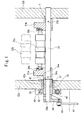
- Fig. 1 is a support configuration drawing of an ink ductor roller, showing Embodiment 1 of the present invention.
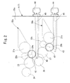
- Fig. 2 is an essential configuration drawing of an inking unit.
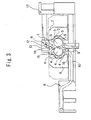
- Fig. 3 is a side view of a four-color perfecting offset press.
- a blanketed impression cylinder 2 equipped with a sheet gripper device and a blanket cylinder 3 without a sheet gripper device are supported nearly horizontally, and their circumferential surfaces are in contact with each other.
- Inking units 6, 7 are movably provided to be movable toward and away from these plate cylinders 4, 5, and can supply ink and water while contacting the plate cylinders 4, 5.
- a delivery cylinder 9 of a delivery unit 8 is disposed below the blanketed impression cylinder 2, and a delivery chain 10 does not cross a space below the position of contact between the circumferential surfaces of the blanketed impression cylinder 2 and the blanket cylinder 3, but is disposed leftwardly of the delivery cylinder 9 in the drawing.
- reference numeral 17 denotes a feeder.
- the sheet which has been fed from the feeder 17 and positioned by the register 11, is transported along a path shown by arrows in the drawing, namely, along the circumferential surfaces of the transfer cylinders 12 to 15, the blanketed impression cylinder 2, the transfer cylinder 16, and the delivery cylinder 9 in this order.
- the sheet thus transported has its opposite surfaces simultaneously printed when passing the point of contact between the blanketed impression cylinder 2 and the blanket cylinder 3 from above toward below.
- ink fountain rollers 21a, 21b which are provided and rotatably supported in ink fountain devices 20a, 20b
- ink ductor rollers 22a, 22b which are provided rotatably in proximity to the ink fountain rollers 21a, 21b and are supported to be swingable about swing fulcrums 29a, 29b.
- the surfaces of the ink ductor rollers 22a, 22b are formed with projections and depressions, and inks are flowed only on the projections.
- ink which the ink ductor roller 22a receives upon contact with the ink fountain roller 21a is directly transferred (passed on) to an ink merger (distribution) roller 23.
- ink which the ink ductor roller 22b receives upon contact with the ink fountain roller 21b is once transferred (passed on) to a first intermediate roller 27 formed from a metal roller, then to a second intermediate roller 28 formed from a rubber roller, and then transferred to the ink merger (distribution) roller 23.
- the distributed inks are transferred to an ink form roller via a group of ink rollers such as an ink distribution roller 24 and an ink oscillating roller (not shown).
- inks of different colors are placed in the two ink fountain devices 20a and 20b.
- color mixing in the ink fountains is not likely to occur, the quality of the printing product is improved, and the volumes of inks stored in the ink fountains are increased, resulting in increased productivity.
- the ink ductor rollers 22a, 22b are supported between a pair of (i.e., right and left) split clamping holders (swing members) 31a and 31b, with no lateral clearance being provided, via bearings 30a and 30b mounted on the shaft ends of the ink ductor rollers 22a and 22b.
- a pair of (i.e., right and left) split clamping holders (swing members) 31a and 31b with no lateral clearance being provided, via bearings 30a and 30b mounted on the shaft ends of the ink ductor rollers 22a and 22b.
- the paired split clamping holders 31a, 31b are fixedly mounted by pins 34a, 34b on a shaft 33 extending between a pair of (i.e., right and left) frames 32a and 32b to be rotatable and slidable.
- An end (left end) of the shaft 33 is formed as a small-diameter portion 33a.
- a sleeve 35 is fitted on the small-diameter portion 33a to be relatively rotatable, and the sleeve 35 is positioned between a stepped portion of the shaft 33 and a bracket 36 which is split-clamped at the shaft end of the small-diameter portion 33a, whereby the sleeve 35 is rendered unmovable in the axial direction.
- An external thread 37 is provided in a part of the outer periphery of the sleeve 35.
- An internal thread 38 screwed to the external thread 37 is provided in an inner peripheral surface of a bearing portion 42a formed integrally with a worm wheel 42.
- the bearing portion 42a is supported by the frame 32a to be rotatable and axially unmovable.
- Reference numeral 40 denotes a stopper fixed to the frame 32a for preventing the worm wheel 42 (bearing portion 42a) from slipping off.
- Reference numeral 41 denotes a key similarly fixed to the frame 32a, and has a front end fitted into a groove 35a of the sleeve 35 for performing whirl-stopping.
- a worm shaft 43 which meshes with the worm wheel 42 in contact with the stopper 40 for preventing slip-off, is integrally connected to an operating shaft 45 (see Fig. 2) provided with a dial-equipped handle 44.
- the shaft 33, the sleeve 35, the worm wheel 42 (bearing portion 42a), the worm shaft 43, and the operating shaft 45 provided with the dial-equipped handle 44 constitute a moving means for moving the split clamping holders 31a, 31b, as swing members, in the axial direction of the ink ductor rollers 22a, 22b.
- the symbol h denotes a clearance for permitting the axial movement of the split clamping holder 31b (i.e., ink ductor rollers 22a, 22b) on the side of the frame 32b.
- a cam follower 46 for rotating the shaft 33 is journaled to the front end of the bracket 36, and a disk-shaped cam 47 which the cam follower 46 makes a rolling contact is supported by the frame 32a to be rotatable in a manner interlocked to the machine.
- the shaft 33, the bracket 36, the cam follower 46, and the cam 47 constitute a swinging means for swinging the split clamping holders 31a, 31b as the swing members.
- the cam follower 46 is formed to be larger in width than the cam 47 in consideration of the axial movement of the shaft 33.
- the shaft 33 is periodically reversibly rotated via the cam follower 46 and the bracket 36 by the cam 47 rotating in a manner interlocked to the machine.
- the split clamping holders 31a, 31b fixedly mounted on the shaft 33 are swung.
- the ink ductor rollers 22a, 22b supported by the split clamping holders 31a, 31b are swung about the swing fulcrums 29a, 29b. Accordingly, on the part of the upper ink fountain device 20a, ink received from the ink fountain roller 21a is directly transferred to the ink merger (distribution) roller 23, whereas on the part of the lower ink fountain device 20b, ink received from the ink fountain roller 21b is once transferred to the first intermediate roller 27, and then to the second intermediate roller 28, and is then transferred to the ink merger (distribution) roller 23.
- the ink ductor rollers 22a, 22b are supported between the pair of split clamping holders 31a and 31b, with a lateral clearance being absent.
- the ink ductor rollers 22a, 22b are initially set, they are certainly set at a fixed position (home position) in the lateral direction.
- the lateral alignment of the projections of the upper and lower ink ductor rollers 22a and 22b with each other, or the lateral alignment of the projections of the upper and lower ink ductor rollers 22a and 22b with the plate cylinders (plate surfaces) 4,5 is carried out by turning the operating shaft 45 from the outside of the machine via the dial-equipped handle 44.
- the shaft 33 is slid by a rotation transmission mechanism composed of the worm shaft 43 and worm wheel 42 rotating integrally with the operating shaft 45, and by a feed screw mechanism composed of the internal thread 38 of the bearing portion 42a and the external thread 37 of the sleeve 35.
- the ink ductor rollers 22a, 22b are moved in the lateral direction via the split clamping holders 31a, 31b fixedly mounted on the shaft 33, whereby their position is adjusted.
- the ink ductor rollers 22a, 22b are moved by a predetermined amount based on a dial reading, so that their position can be adjusted with high accuracy by a visual check. Moreover, unlike conventional procedure, the ink ductor rollers 22a, 22b are not directly moved, but are operated from the outside of the machine via the shaft 33, etc. Thus, the position of the ink ductor rollers 22a, 22b can be adjusted during operation, without stopping the machine.
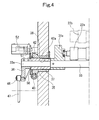
- Fig. 4 is an essential configuration drawing of an inking unit, showing Embodiment 2 of the present invention.
- Fig. 5 is a configuration drawing of a motor drive portion.
- Embodiment 1 This is an embodiment in which the worm shaft 43 in Embodiment 1 is rotationally driven by a motor 53 instead of by the operating shaft 45 having the dial-equipped handle 44, and the amount of rotation of the bearing portion 42a integral with the worm wheel 42 (i.e., the amount of movement of the ink ductor rollers 22a, 22b) is detected by a potentiometer 52 via gears 50, 51.
- a potentiometer 52 is the same as those in Embodiment 1, and thus duplicate explanations are omitted, with the same members as those in Fig. 1 being assigned the same numerals as those in Fig. 1.
- Fig. 6 is an essential configuration drawing of an inking unit, showing Embodiment 3 of the present invention.
- Embodiments 1 and 2 This is an embodiment in which the worm shaft 43 in Embodiments 1 and 2 is built in the frame 32a to achieve the compact configuration of the machine.
- Other features are the same as those in Embodiment 1, and thus duplicate explanations are omitted, with the same members as those in Figs. 1 and 4 being assigned the same numerals as those in Figs. 1 and 4.
- Fig. 7 is an essential configuration drawing of an inking unit, showing Embodiment 4 of the present invention.
- An operating shaft 45 as a drive means, having a dial-equipped handle 44 is supported parallel to the shaft 33 and rotatably by the frame 32b via a support member 64, which is assembled in an L-shape and concurrently serves as a guide for a bracket 61 (to be described later) as a moving member.
- the aforementioned disk 63 is located between, and in rolling contact with, the paired right and left rollers 62a and 62b.
- the operating shaft 45 is turned via the dial-equipped handle 44, whereby the bracket 61 is moved laterally by a feed screw mechanism, and the shaft 33 is slid via the disk 63 interposed between the right and left paired rollers 62a and 62b moving integrally with the bracket 61.
- Other features are the same as those in Embodiment 1, and thus duplicate explanations are omitted, with the same members as those in Fig. 1 being assigned the same numerals as those in Fig. 1.
- the ink transferred to the lower ink ductor roller may be directly transferred to the ink merger roller, or the ink from the upper ink ductor roller may be transferred to the ink merger roller via one or more intermediate rollers as is the ink from the lower ink ductor roller.
- the above embodiments disclose examples in which a pair of the ink fountain rollers and a pair of the ink ductor rollers are provided in the vertical direction, but may be provided in the lateral direction.
- examples of applying the present invention to rainbow printing are disclosed, but the present invention can be applied to a printing press which does not carry out rainbow printing.
- Such variations are not to be regarded as a departure from the spirit and scope of the invention, and all such modifications as would be obvious to one skilled in the art are intended to be included within the scope of the following claims.
Landscapes
- Inking, Control Or Cleaning Of Printing Machines (AREA)
Abstract
Description
- This invention relates to an inking device of a printing press and, more particularly, to an inking device of a printing press preferred for rainbow printing.
- A rainbow printing press is disclosed, for example, in
Japanese Patent Application Laid-Open No. 2001-310447 - Thus, lateral alignment between the upper and lower ink ductor rollers is important, and lateral alignment of the projections of the upper and lower ink ductor rollers with plate cylinders (plate surfaces) is also important.
- In performing adjusting work for this purpose, it has been common practice to loosen split clamping holders, which fix bearings for the ink ductor roller, and move the ink ductor roller in a lateral direction directly and manually within the lateral clearances of the split clamping holders.
- However, the above-mentioned adjusting work for the ink ductor roller has posed the following problems:
- (1) During the adjusting work, the machine has to be stopped. During sampling, the machine has to be driven. Such operations repeated several times result in great losses of the adjusting time and test printing sheets.
- (2) Since the adjusting work for the ink ductor roller is done manually, fine adjustment is difficult and printing accuracy cannot be increased.
- (3) When initially setting the ink ductor roller, it is difficult to know where in the clearances of the split clamping holders the ink ductor roller is located, and it is hard to determine the home position.
- (4) In the case of rainbow printing, the shape of the projections and depressions formed on the surface of the ink ductor roller differs according to the printing product. Thus, whenever printing is changed, the ink ductor roller has to be replaced, requiring frequent adjusting work for the ink ductor roller.
- The present invention has been proposed in light of the above-described circumstances. The present invention provides an inking device of a printing press which can easily set an ink ductor roller at a home position, and can adjust the position of the ink ductor roller during operation of the machine by moving the ink ductor roller laterally.
- A first aspect of the present invention is an inking device of a printing press, including an ink ductor roller reciprocating between a receipt position, at which the ink ductor roller contacts an ink fountain roller to receive ink, and a transfer position, at which the ink ductor roller contacts a roller located downstream in an ink transfer direction to pass the ink on to the roller, the inking device comprising: a pair of swing members supporting the ink ductor roller and supported swingably; and moving means for moving the pair of swing members in an axial direction of the ink ductor roller.
- According to a second aspect of the present invention, the swing members may be fixedly mounted on a shaft extending between a pair of frames to be rotatable and slidable, and the shaft may be slid by the moving means and rotated by swinging means.
- According to a third aspect of the present invention, the moving means may include a sleeve fitted on the shaft to be relatively rotatable and unmovable in an axial direction, and having a thread provided on an outer periphery of the sleeve, a worm wheel fitted to the outer periphery of the sleeve and supported by the frame to be rotatable and unmovable in the axial direction, a worm shaft meshing with the worm wheel, and drive means for rotationally driving the worm shaft.
- According to a fourth aspect of the present invention, the worm shaft may be built in the frame.
- According to a fifth aspect of the present invention, the moving means may include an engaging portion provided on the shaft, a moving member having an engaged portion in engagement with the engaging portion and supported to be movable in an axial direction of the shaft, and drive means for moving the moving member.
- According to a sixth aspect of the present invention, the engaging portion may be a board member attached to the shaft, the engaged portion may be a restraint member provided in the moving member for restraining a relative movement of the moving member in the axial direction of the shaft with respect to the board member, and the drive means may be a thread.
- According to a seventh aspect of the present invention, the swinging means may include a cam follower journaled by the shaft via a bracket, and a disk-shaped cam supported on a side of the frame to be rotatable for rolling contact with the cam follower.
- According to an eighthaspect of the present invention, the cam follower and the cam may always contact each other in a range of movement of the shaft.
- According to a ninth aspect of the present invention, the ink ductor roller may have projections and depressions on a circumferential surface thereof.
- According to a tenth aspect of the present invention, the ink ductor roller may be supported between the pair of swing members, with no clearance being provided in the axial direction of the ink ductor roller.
- According to an eleventh aspect of the present invention, two of the ink fountain rollers and two of the ink ductor rollers may be provided, and the ink transferred to each ink ductor roller may be transferred to an ink merger roller provided downstream, in the ink transfer direction, of each ink ductor roller.
- According to a twelfth aspect of the present invention, the ink transferred to one of the ink ductor rollers may be directly transferred to the ink merger roller, and the ink transferred to the other of the ink ductor rollers may be transferred to the ink merger roller via one or more intermediate rollers.
- According to the inking device of the printing press concerned with the present invention, the ink ductor roller is supported between a pair of the swing members with no lateral clearance being provided, and the swing members are moved in the axial direction of the ink ductor roller by the moving means. By so doing, the ink ductor roller can be easily set at the home position, and the ink ductor roller is laterally moved even during operation of the machine to achieve its position adjustment.
- The present invention will become more fully understood from the detailed description given hereinbelow and the accompanying drawings which are given by way of illustration only, and thus are not limitative of the present invention, and wherein:
- Fig. 1 is a support configuration drawing of an ink ductor roller, showing Embodiment 1 of the present invention;
- Fig. 2 is an essential configuration drawing of an inking unit;
- Fig. 3 is a side view of a four-color perfecting offset press;
- Fig. 4 is an essential configuration drawing of an inking unit, showing Embodiment 2 of the present invention;
- Fig. 5 is a configuration drawing of a motor drive portion;
- Fig. 6 is an essential configuration drawing of an inking unit, showing Embodiment 3 of the present invention; and
- Fig. 7 is an essential configuration drawing of an inking unit, showing
Embodiment 4 of the present invention. - An inking device of a printing press according to the present invention will now be described in detail by embodiments with reference to the accompanying drawings.
- Fig. 1 is a support configuration drawing of an ink ductor roller, showing Embodiment 1 of the present invention. Fig. 2 is an essential configuration drawing of an inking unit. Fig. 3 is a side view of a four-color perfecting offset press.
- In a printing unit 1 of the present printing press, as shown in Fig. 3, a blanketed impression cylinder 2 equipped with a sheet gripper device and a blanket cylinder 3 without a sheet gripper device are supported nearly horizontally, and their circumferential surfaces are in contact with each other.
- Four
plate cylinders 4 are arranged on the circumferential surface of the blanketed impression cylinder 2, and fourplate cylinders 5 are arranged on the circumferential surface of the blanket cylinder 3. Inkingunits plate cylinders plate cylinders - A
delivery cylinder 9 of adelivery unit 8 is disposed below the blanketed impression cylinder 2, and adelivery chain 10 does not cross a space below the position of contact between the circumferential surfaces of the blanketed impression cylinder 2 and the blanket cylinder 3, but is disposed leftwardly of thedelivery cylinder 9 in the drawing. -
Transfer cylinders 12 to 15, which have sheet gripper devices and transfer a sheet from aregister 11 to the blanketed impression cylinder 2, are provided. Similarly, atransfer cylinder 16, which has a sheet gripper device and transfers the sheet from the blanketed impression cylinder 2 to thedelivery cylinder 9, is provided. In Fig. 3, reference numeral 17 denotes a feeder. - Thus, the sheet, which has been fed from the feeder 17 and positioned by the
register 11, is transported along a path shown by arrows in the drawing, namely, along the circumferential surfaces of thetransfer cylinders 12 to 15, the blanketed impression cylinder 2, thetransfer cylinder 16, and thedelivery cylinder 9 in this order. The sheet thus transported has its opposite surfaces simultaneously printed when passing the point of contact between the blanketed impression cylinder 2 and the blanket cylinder 3 from above toward below. - In the
inking units ink fountain rollers ink fountain devices ink ductor rollers ink fountain rollers swing fulcrums ink ductor rollers - On the part of the upper
ink fountain device 20a, ink which theink ductor roller 22a receives upon contact with theink fountain roller 21a is directly transferred (passed on) to an ink merger (distribution)roller 23. On the part of the lowerink fountain device 20b, on the other hand, ink which theink ductor roller 22b receives upon contact with theink fountain roller 21b is once transferred (passed on) to a firstintermediate roller 27 formed from a metal roller, then to a secondintermediate roller 28 formed from a rubber roller, and then transferred to the ink merger (distribution)roller 23. From the ink merger (distribution)roller 23, the distributed inks are transferred to an ink form roller via a group of ink rollers such as anink distribution roller 24 and an ink oscillating roller (not shown). - Thus, when printing, called rainbow printing, is performed with boundaries between respective colors being blurred, inks of different colors are placed in the two
ink fountain devices - The
ink ductor rollers bearings ink ductor rollers - The paired
split clamping holders pins shaft 33 extending between a pair of (i.e., right and left)frames - An end (left end) of the
shaft 33 is formed as a small-diameter portion 33a. Asleeve 35 is fitted on the small-diameter portion 33a to be relatively rotatable, and thesleeve 35 is positioned between a stepped portion of theshaft 33 and abracket 36 which is split-clamped at the shaft end of the small-diameter portion 33a, whereby thesleeve 35 is rendered unmovable in the axial direction. - An
external thread 37 is provided in a part of the outer periphery of thesleeve 35. Aninternal thread 38 screwed to theexternal thread 37 is provided in an inner peripheral surface of a bearingportion 42a formed integrally with aworm wheel 42. The bearingportion 42a is supported by theframe 32a to be rotatable and axially unmovable.Reference numeral 40 denotes a stopper fixed to theframe 32a for preventing the worm wheel 42 (bearingportion 42a) from slipping off.Reference numeral 41 denotes a key similarly fixed to theframe 32a, and has a front end fitted into agroove 35a of thesleeve 35 for performing whirl-stopping. - A
worm shaft 43, which meshes with theworm wheel 42 in contact with thestopper 40 for preventing slip-off, is integrally connected to an operating shaft 45 (see Fig. 2) provided with a dial-equippedhandle 44. Thus, theshaft 33, thesleeve 35, the worm wheel 42 (bearingportion 42a), theworm shaft 43, and the operatingshaft 45 provided with the dial-equippedhandle 44 constitute a moving means for moving thesplit clamping holders ink ductor rollers split clamping holder 31b (i.e.,ink ductor rollers frame 32b. - A
cam follower 46 for rotating theshaft 33 is journaled to the front end of thebracket 36, and a disk-shapedcam 47 which thecam follower 46 makes a rolling contact is supported by theframe 32a to be rotatable in a manner interlocked to the machine. Thus, theshaft 33, thebracket 36, thecam follower 46, and thecam 47 constitute a swinging means for swinging thesplit clamping holders cam follower 46 is formed to be larger in width than thecam 47 in consideration of the axial movement of theshaft 33. - Because of the above-described configuration, the
shaft 33 is periodically reversibly rotated via thecam follower 46 and thebracket 36 by thecam 47 rotating in a manner interlocked to the machine. As a result, thesplit clamping holders shaft 33 are swung. - Thus, the
ink ductor rollers split clamping holders swing fulcrums ink fountain device 20a, ink received from theink fountain roller 21a is directly transferred to the ink merger (distribution)roller 23, whereas on the part of the lowerink fountain device 20b, ink received from theink fountain roller 21b is once transferred to the firstintermediate roller 27, and then to the secondintermediate roller 28, and is then transferred to the ink merger (distribution)roller 23. - According to the present embodiment, the
ink ductor rollers split clamping holders ink ductor rollers - Thus, the lateral alignment of the projections of the upper and lower
ink ductor rollers ink ductor rollers shaft 45 from the outside of the machine via the dial-equippedhandle 44. - That is, upon rotation of the operating
shaft 45, theshaft 33 is slid by a rotation transmission mechanism composed of theworm shaft 43 andworm wheel 42 rotating integrally with the operatingshaft 45, and by a feed screw mechanism composed of theinternal thread 38 of the bearingportion 42a and theexternal thread 37 of thesleeve 35. In accordance with this slide, theink ductor rollers split clamping holders shaft 33, whereby their position is adjusted. - On this occasion, the
ink ductor rollers ink ductor rollers shaft 33, etc. Thus, the position of theink ductor rollers - Fig. 4 is an essential configuration drawing of an inking unit, showing Embodiment 2 of the present invention. Fig. 5 is a configuration drawing of a motor drive portion.
- This is an embodiment in which the
worm shaft 43 in Embodiment 1 is rotationally driven by amotor 53 instead of by the operatingshaft 45 having the dial-equippedhandle 44, and the amount of rotation of the bearingportion 42a integral with the worm wheel 42 (i.e., the amount of movement of theink ductor rollers potentiometer 52 viagears - According to the above-described configuration, the advantage that the position adjustment of the
ink ductor rollers - Fig. 6 is an essential configuration drawing of an inking unit, showing Embodiment 3 of the present invention.
- This is an embodiment in which the
worm shaft 43 in Embodiments 1 and 2 is built in theframe 32a to achieve the compact configuration of the machine. Other features are the same as those in Embodiment 1, and thus duplicate explanations are omitted, with the same members as those in Figs. 1 and 4 being assigned the same numerals as those in Figs. 1 and 4. - Fig. 7 is an essential configuration drawing of an inking unit, showing
Embodiment 4 of the present invention. - This is an embodiment in which opposite end portions of the
shaft 33 in Embodiment 1 are formed as small-diameter portions diameter portions frames needle bearings bearings 39a, 39b to be rotatable and movable (slidable) in the axial direction of theneedle bearings disk 63, as an engagement portion and a board member, is attached to the small-diameter portion 33b on the side of theframe 32b of theshaft 33. - An operating
shaft 45, as a drive means, having a dial-equippedhandle 44 is supported parallel to theshaft 33 and rotatably by theframe 32b via asupport member 64, which is assembled in an L-shape and concurrently serves as a guide for a bracket 61 (to be described later) as a moving member. A pair of (i.e., right and left)rollers bracket 61 which is screwed to a threadedportion 45a of the operatingshaft 45 and slidably fitted on aguide rod portion 64a of thesupport member 64. Theaforementioned disk 63 is located between, and in rolling contact with, the paired right and leftrollers - Thus, the operating
shaft 45 is turned via the dial-equippedhandle 44, whereby thebracket 61 is moved laterally by a feed screw mechanism, and theshaft 33 is slid via thedisk 63 interposed between the right and left pairedrollers bracket 61. Other features are the same as those in Embodiment 1, and thus duplicate explanations are omitted, with the same members as those in Fig. 1 being assigned the same numerals as those in Fig. 1. - According to the above-described configuration, in which only the
shaft 33 is moved, the advantage that the moving means for the shaft 33 (split clampingholders - While the present invention has been described by the above embodiments, it is to be understood that the invention is not limited to these embodiments, but may be varied in many other ways. For example, gears or chain belts may be used instead of the
worm shaft 43 and theworm wheel 42 in Embodiments 1 to 3. Alternatively, a grooved pulley may be used to move theshaft 33 axially. In the above respective embodiments, the ink transferred to the upper ink ductor roller is directly transferred to the ink merger roller, while the ink transferred to the lower ink ductor roller is transferred to the ink merger roller via the two intermediate rollers. However, the ink transferred to the lower ink ductor roller may be directly transferred to the ink merger roller, or the ink from the upper ink ductor roller may be transferred to the ink merger roller via one or more intermediate rollers as is the ink from the lower ink ductor roller. The above embodiments disclose examples in which a pair of the ink fountain rollers and a pair of the ink ductor rollers are provided in the vertical direction, but may be provided in the lateral direction. In the respective embodiments, examples of applying the present invention to rainbow printing are disclosed, but the present invention can be applied to a printing press which does not carry out rainbow printing. Such variations are not to be regarded as a departure from the spirit and scope of the invention, and all such modifications as would be obvious to one skilled in the art are intended to be included within the scope of the following claims.
Claims (12)
- An inking device of a printing press, including an ink ductor roller (22a, 22b) reciprocating between a receipt position, at which said ink ductor roller contacts an ink fountain roller (21a, 21b) to receive ink, and a transfer position, at which said ink ductor roller contacts a roller (23, 27) located downstream in an ink transfer direction to pass the ink on to said roller,
said inking device comprising:a pair of swing members (31a, 31b) supporting said ink ductor roller and supported swingably; andmoving means (33, 35, 42, 43, 44, 45) for moving said pair of swing members in an axial direction of said ink ductor roller. - The inking device of a printing press according to claim 1, characterized in that said swing members are fixedly mounted on a shaft (33) extending between a pair of frames (32a, 32b) to be rotatable and slidable, and said shaft is slid by said moving means and rotated by swinging means (33, 36, 46, 47).
- The inking device of a printing press according to claim 2, characterized in that said moving means includes a sleeve (35) fitted on said shaft to be relatively rotatable and unmovable in an axial direction, and having a thread (37) provided on an outer periphery of said sleeve, a worm wheel (42) fitted to the outer periphery of said sleeve and supported by said frame to be rotatable and unmovable in the axial direction, a worm shaft (43) meshing with said worm wheel, and drive means (45, 53) forrotationallydriving said worm shaft (43).
- The inking device of a printing press according to claim 3, characterized in that said worm shaft (43) is built in said frame.
- The inking device of a printing press according to claim 2, characterized in that said moving means includes an engaging portion (63) provided on said shaft, a moving member (61) having an engaged portion (62a, 62b) in engagement with said engaging portion and supported to be movable in an axial direction of said shaft, and drive means (44, 45, 45a) for moving said moving member.
- The inking device of a printing press according to claim 5, characterized in that said engaging portion is a boardmember (63) attached to said shaft, saidengagedportion is a restraint member (62a, 62b) provided in said moving member for restraining a relative movement of said moving member in the axial direction of said shaft with respect to said board member, and said drive means is a thread (45a).
- The inking device of a printing press according to claim 2, characterized in that said swinging means includes a cam follower (46) journaled by said shaft via a bracket (36), and a disk-shaped cam (47) supported on a side of said frame to be rotatable for rolling contact with said cam follower (46).
- The inking device of a printing press according to claim 7, characterized in that said cam follower (46) and said cam (47) always contact each other in a range of movement of said shaft.
- The inking device of a printing press according to claim 1, characterized in that said ink ductor roller has projections and depressions on a circumferential surface thereof.
- The inking device of a printing press according to claim 1, characterized in that said ink ductor roller is supported between said pair of swing members, with no clearance being provided in the axial direction of said ink ductor roller.
- The inking device of a printing press according to claim 1, characterized in that two of said ink fountain rollers (21a, 21b) and two of said ink ductor rollers (22a, 22b) are provided, and the ink transferred to each said inkductor roller is transferred to an ink merger roller (23) provided downstream, in the ink transfer direction, of each said ink ductor roller.
- The inking device of a printing press according to claim 11, characterized in that the ink transferred to one of said ink ductor rollers (22a, 22b) is directly transferred to said ink merger roller, and the ink transferred to other of said ink ductor rollers (22a, 22b) is transferred to said ink merger roller via one or more intermediate rollers (27, 28).
Applications Claiming Priority (1)
| Application Number | Priority Date | Filing Date | Title |
|---|---|---|---|
| JP2005187985A JP2007007881A (en) | 2005-06-28 | 2005-06-28 | Inking device of printing machine |
Publications (2)
| Publication Number | Publication Date |
|---|---|
| EP1738907A2 true EP1738907A2 (en) | 2007-01-03 |
| EP1738907A3 EP1738907A3 (en) | 2007-07-25 |
Family
ID=37192498
Family Applications (1)
| Application Number | Title | Priority Date | Filing Date |
|---|---|---|---|
| EP06012153A Withdrawn EP1738907A3 (en) | 2005-06-28 | 2006-06-13 | Inking device of printing press |
Country Status (5)
| Country | Link |
|---|---|
| US (1) | US20070006757A1 (en) |
| EP (1) | EP1738907A3 (en) |
| JP (1) | JP2007007881A (en) |
| CN (1) | CN1891459A (en) |
| RU (1) | RU2006122899A (en) |
Cited By (2)
| Publication number | Priority date | Publication date | Assignee | Title |
|---|---|---|---|---|
| CN103182834A (en) * | 2013-04-03 | 2013-07-03 | 潍坊浩田印刷机械有限公司 | Continuous ink supply system for proofing machine |
| EP2998117A1 (en) | 2014-09-19 | 2016-03-23 | KBA-NotaSys SA | Inking apparatus of a printing press, printing press comprising the same and method of producing a vibrator roller |
Families Citing this family (23)
| Publication number | Priority date | Publication date | Assignee | Title |
|---|---|---|---|---|
| CN101934630B (en) * | 2009-07-03 | 2012-06-27 | 中国人民银行印制科学技术研究所 | Single-plate bicolor split separated inking device and printing equipment with same |
| US10592416B2 (en) | 2011-09-30 | 2020-03-17 | Oracle International Corporation | Write-back storage cache based on fast persistent memory |
| ES2604760T3 (en) * | 2012-10-10 | 2017-03-09 | Koenig & Bauer Ag | Inking mechanism of a printing group, printing group as well as procedure for the operation of a printing group |
| US10642837B2 (en) | 2013-03-15 | 2020-05-05 | Oracle International Corporation | Relocating derived cache during data rebalance to maintain application performance |
| CN105073425A (en) * | 2013-04-04 | 2015-11-18 | 小森公司 | Ink-feeding roller and manufacturing method therefor |
| CN106183405B (en) * | 2016-08-31 | 2019-02-05 | 苏州斯莱克精密设备股份有限公司 | An ink unit of a metal can printing machine |
| DE102017202381A1 (en) * | 2017-02-15 | 2018-08-16 | Kba-Metalprint Gmbh | Method for printing hollow bodies |
| EP3375610B1 (en) * | 2017-03-14 | 2019-04-17 | KBA-NotaSys SA | Sheet-fed printing press for simultaneous recto-verso printing of sheets, in particular for the production of security documents |
| US10803039B2 (en) | 2017-05-26 | 2020-10-13 | Oracle International Corporation | Method for efficient primary key based queries using atomic RDMA reads on cache friendly in-memory hash index |
| US10719446B2 (en) | 2017-08-31 | 2020-07-21 | Oracle International Corporation | Directly mapped buffer cache on non-volatile memory |
| GB2566944B (en) * | 2017-09-26 | 2022-08-03 | De La Rue Int Ltd | Method of forming microimage elements |
| GB2603656A (en) * | 2017-09-26 | 2022-08-10 | De La Rue Int Ltd | Method of forming microimage elements |
| US10732836B2 (en) | 2017-09-29 | 2020-08-04 | Oracle International Corporation | Remote one-sided persistent writes |
| US10956335B2 (en) | 2017-09-29 | 2021-03-23 | Oracle International Corporation | Non-volatile cache access using RDMA |
| US11086876B2 (en) | 2017-09-29 | 2021-08-10 | Oracle International Corporation | Storing derived summaries on persistent memory of a storage device |
| US10802766B2 (en) | 2017-09-29 | 2020-10-13 | Oracle International Corporation | Database with NVDIMM as persistent storage |
| CN107627729A (en) * | 2017-10-20 | 2018-01-26 | 北京中标新正防伪技术有限公司 | One kind takes ink roller |
| CN111433035B (en) * | 2017-12-14 | 2022-04-15 | 艾美企画股份有限公司 | Inking roller of printing machine and protection component of electromagnetic valve built in inking roller |
| CN109334250A (en) * | 2018-12-12 | 2019-02-15 | 北方民族大学 | A phase ink transfer structure for a split two-color offset press |
| CN109910432B (en) * | 2019-04-03 | 2020-11-13 | 北京印钞有限公司 | Ink supply system with planetary reduction cam device |
| US11413859B1 (en) * | 2021-02-12 | 2022-08-16 | Stolle Machinery Company, Llc | Ductor roll assembly, ink station assembly and can decorator employing same |
| CN115107345B (en) * | 2021-03-23 | 2023-10-20 | 南京造币有限公司 | A modular combined double-sided anti-counterfeiting shading printing machine |
| CN116619890B (en) * | 2023-03-06 | 2025-08-12 | 升辉新材料股份有限公司 | Online printing device of bag making machine |
Citations (1)
| Publication number | Priority date | Publication date | Assignee | Title |
|---|---|---|---|---|
| DE8427796U1 (en) | 1984-09-21 | 1986-07-31 | Heidelberger Druckmaschinen Ag, 6900 Heidelberg | Device for transferring color into the inking unit of printing machines |
Family Cites Families (17)
| Publication number | Priority date | Publication date | Assignee | Title |
|---|---|---|---|---|
| US2467199A (en) * | 1945-03-29 | 1949-04-12 | Time Inc | Ink transfer roller |
| CH258319A (en) * | 1946-10-31 | 1948-11-30 | Winkler Fallert & Co Maschf | Lift lock on printing machines for quick replacement of the lift rollers. |
| DE1129506B (en) * | 1958-08-19 | 1962-05-17 | Albert Schnellpressen | Inking unit for rotary printing machines |
| DE1925018A1 (en) * | 1969-05-16 | 1970-11-26 | Koenig & Bauer Schnellpressfab | Inking switch drive for inking units of printing machines |
| US3688696A (en) * | 1970-05-08 | 1972-09-05 | Harris Intertype Corp | Motorized ductor roll |
| US3698313A (en) * | 1970-06-25 | 1972-10-17 | North American Rockwell | Means for oscillating and silencing a ductor roller in a printing press |
| US3916791A (en) * | 1972-06-14 | 1975-11-04 | Roland Offsetmaschf | Adjusting device for the lateral ink distribution on printing presses |
| US4198908A (en) * | 1977-03-11 | 1980-04-22 | Veb Polygraph Druckmaschinenwerke Leipzig | Drive for an ink supplying device of a rotary printing press |
| JPS5672960A (en) * | 1979-11-19 | 1981-06-17 | Tokyo Kikai Seisakusho:Kk | Vibrator device of ink cylinder in rotary printer |
| DE3434646C1 (en) * | 1984-09-21 | 1985-11-07 | Heidelberger Druckmaschinen Ag, 6900 Heidelberg | Lifter inking unit of a printing press |
| US5152224A (en) * | 1990-09-14 | 1992-10-06 | Harris Graphics Corporation | Isolated ink feed mechanism |
| JPH05162290A (en) * | 1991-12-13 | 1993-06-29 | Mitsubishi Heavy Ind Ltd | Ink feeder of printer |
| JP2000062134A (en) * | 1998-08-21 | 2000-02-29 | Komori Corp | Printer |
| JP2000094646A (en) * | 1998-09-18 | 2000-04-04 | Komori Corp | Printing machine ink unit |
| JP2001310447A (en) * | 2000-04-28 | 2001-11-06 | Komori Corp | Ink unit for rotary printing press |
| DE10028479A1 (en) * | 2000-06-08 | 2001-12-13 | Roland Man Druckmasch | Chamber doctor blade has opening, closure element, sealing surfaces and housing |
| JP2004322504A (en) * | 2003-04-25 | 2004-11-18 | Mitsubishi Heavy Ind Ltd | Ink supply device of printing machine and vibrating roller |
-
2005
- 2005-06-28 JP JP2005187985A patent/JP2007007881A/en active Pending
-
2006
- 2006-06-13 EP EP06012153A patent/EP1738907A3/en not_active Withdrawn
- 2006-06-26 US US11/474,470 patent/US20070006757A1/en not_active Abandoned
- 2006-06-27 RU RU2006122899/12A patent/RU2006122899A/en not_active Application Discontinuation
- 2006-06-28 CN CNA2006100957422A patent/CN1891459A/en active Pending
Patent Citations (1)
| Publication number | Priority date | Publication date | Assignee | Title |
|---|---|---|---|---|
| DE8427796U1 (en) | 1984-09-21 | 1986-07-31 | Heidelberger Druckmaschinen Ag, 6900 Heidelberg | Device for transferring color into the inking unit of printing machines |
Cited By (4)
| Publication number | Priority date | Publication date | Assignee | Title |
|---|---|---|---|---|
| CN103182834A (en) * | 2013-04-03 | 2013-07-03 | 潍坊浩田印刷机械有限公司 | Continuous ink supply system for proofing machine |
| EP2998117A1 (en) | 2014-09-19 | 2016-03-23 | KBA-NotaSys SA | Inking apparatus of a printing press, printing press comprising the same and method of producing a vibrator roller |
| WO2016042482A2 (en) | 2014-09-19 | 2016-03-24 | Kba-Notasys Sa | Inking apparatus of a printing press, printing press comprising the same and method of producing a vibrator roller |
| US10220608B2 (en) | 2014-09-19 | 2019-03-05 | Kba-Notasys Sa | Inking apparatus of a printing press, printing press comprising the same and method of producing a vibrator roller |
Also Published As
| Publication number | Publication date |
|---|---|
| US20070006757A1 (en) | 2007-01-11 |
| RU2006122899A (en) | 2008-01-10 |
| JP2007007881A (en) | 2007-01-18 |
| CN1891459A (en) | 2007-01-10 |
| EP1738907A3 (en) | 2007-07-25 |
Similar Documents
| Publication | Publication Date | Title |
|---|---|---|
| US20070006757A1 (en) | Inking device of printing press | |
| JP2550047B2 (en) | Printing device | |
| EP1724115B1 (en) | Ink fountain device | |
| JPH082638B2 (en) | Image adjustment device for sheet-fed printing press | |
| EP3632684B1 (en) | Printing mechanism of offset printing machine | |
| US7814829B2 (en) | Cylindrical body supporting device | |
| US4986176A (en) | Device for connecting and disconnecting dampening system and inking system in offset printing machine | |
| US5460088A (en) | Printing press | |
| ATE138014T1 (en) | COLOR APPARATUS FOR PRINTING MACHINES | |
| WO2014203684A1 (en) | Intaglio printing machine and intaglio printing method | |
| EP3466689B1 (en) | Printing apparatus | |
| US4833988A (en) | Inking device for printing apparatus | |
| JPH09201938A (en) | Apparatus for carrying bearing carriage being movable in carriage guide | |
| JP4700727B2 (en) | Cantilever blanket lifting mechanism | |
| JPH0734670Y2 (en) | Nip pressure adjustment mechanism | |
| JPH0775883B2 (en) | Sheet guide for sheet printing machine Sheet guide to drum | |
| GB2096543A (en) | Adjustments in printing presses | |
| JP2852761B2 (en) | Adjustment device for gap between cylinders of printing press | |
| CN213035458U (en) | A pressure adjustment mechanism of a cardboard printing device | |
| CN218640524U (en) | Adjusting device of printing machine transmission mechanism | |
| CN115027126B (en) | Bottom die quick-change assembly and rotary printing machine | |
| JP2003072031A (en) | Ink transfer unit for printer | |
| JP2015003424A (en) | Intaglio printing machine | |
| US687030A (en) | Cylinder printing-machine. | |
| JP3487835B2 (en) | Ink fountain blade adjustment device for printing press |
Legal Events
| Date | Code | Title | Description |
|---|---|---|---|
| PUAI | Public reference made under article 153(3) epc to a published international application that has entered the european phase |
Free format text: ORIGINAL CODE: 0009012 |
|
| AK | Designated contracting states |
Kind code of ref document: A2 Designated state(s): AT BE BG CH CY CZ DE DK EE ES FI FR GB GR HU IE IS IT LI LT LU LV MC NL PL PT RO SE SI SK TR |
|
| AX | Request for extension of the european patent |
Extension state: AL BA HR MK YU |
|
| PUAL | Search report despatched |
Free format text: ORIGINAL CODE: 0009013 |
|
| AK | Designated contracting states |
Kind code of ref document: A3 Designated state(s): AT BE BG CH CY CZ DE DK EE ES FI FR GB GR HU IE IS IT LI LT LU LV MC NL PL PT RO SE SI SK TR |
|
| AX | Request for extension of the european patent |
Extension state: AL BA HR MK YU |
|
| 17P | Request for examination filed |
Effective date: 20080111 |
|
| AKX | Designation fees paid |
Designated state(s): AT BE BG CH CY CZ DE DK EE ES FI FR GB GR HU IE IS IT LI LT LU LV MC NL PL PT RO SE SI SK TR |
|
| 17Q | First examination report despatched |
Effective date: 20080313 |
|
| STAA | Information on the status of an ep patent application or granted ep patent |
Free format text: STATUS: THE APPLICATION IS DEEMED TO BE WITHDRAWN |
|
| 18D | Application deemed to be withdrawn |
Effective date: 20110103 |