EP1738723A1 - Acetabular liner extraction device and kit - Google Patents
Acetabular liner extraction device and kit Download PDFInfo
- Publication number
- EP1738723A1 EP1738723A1 EP06253087A EP06253087A EP1738723A1 EP 1738723 A1 EP1738723 A1 EP 1738723A1 EP 06253087 A EP06253087 A EP 06253087A EP 06253087 A EP06253087 A EP 06253087A EP 1738723 A1 EP1738723 A1 EP 1738723A1
- Authority
- EP
- European Patent Office
- Prior art keywords
- jaw
- liner
- extraction device
- handle
- jaws
- Prior art date
- Legal status (The legal status is an assumption and is not a legal conclusion. Google has not performed a legal analysis and makes no representation as to the accuracy of the status listed.)
- Granted
Links
- 238000000605 extraction Methods 0.000 title claims abstract description 171
- 230000000149 penetrating effect Effects 0.000 claims abstract description 20
- 230000033001 locomotion Effects 0.000 claims description 18
- 229920000642 polymer Polymers 0.000 claims description 13
- 229910052751 metal Inorganic materials 0.000 claims description 9
- 239000002184 metal Substances 0.000 claims description 9
- 238000001356 surgical procedure Methods 0.000 claims description 8
- 230000035515 penetration Effects 0.000 claims description 7
- 230000007246 mechanism Effects 0.000 description 31
- 238000000034 method Methods 0.000 description 25
- 210000001624 hip Anatomy 0.000 description 24
- 210000000988 bone and bone Anatomy 0.000 description 12
- 210000000689 upper leg Anatomy 0.000 description 12
- 210000000845 cartilage Anatomy 0.000 description 10
- 239000007943 implant Substances 0.000 description 9
- 210000000588 acetabulum Anatomy 0.000 description 8
- 210000001503 joint Anatomy 0.000 description 8
- 239000004698 Polyethylene Substances 0.000 description 7
- -1 polyethylene Polymers 0.000 description 7
- 229920000573 polyethylene Polymers 0.000 description 7
- 208000012659 Joint disease Diseases 0.000 description 6
- 238000011882 arthroplasty Methods 0.000 description 6
- 210000002414 leg Anatomy 0.000 description 6
- 239000000463 material Substances 0.000 description 6
- 239000007787 solid Substances 0.000 description 6
- 208000036487 Arthropathies Diseases 0.000 description 5
- 206010003246 arthritis Diseases 0.000 description 5
- POIUWJQBRNEFGX-XAMSXPGMSA-N cathelicidin Chemical compound C([C@@H](C(=O)N[C@@H](CCCNC(N)=N)C(=O)N[C@@H](CCCCN)C(=O)N[C@@H](CO)C(=O)N[C@@H](CCCCN)C(=O)N[C@@H](CCC(O)=O)C(=O)N[C@@H](CCCCN)C(=O)N[C@@H]([C@@H](C)CC)C(=O)NCC(=O)N[C@@H](CCCCN)C(=O)N[C@@H](CCC(O)=O)C(=O)N[C@@H](CC=1C=CC=CC=1)C(=O)N[C@@H](CCCCN)C(=O)N[C@@H](CCCNC(N)=N)C(=O)N[C@@H]([C@@H](C)CC)C(=O)N[C@@H](C(C)C)C(=O)N[C@@H](CCC(N)=O)C(=O)N[C@@H](CCCNC(N)=N)C(=O)N[C@@H]([C@@H](C)CC)C(=O)N[C@@H](CCCCN)C(=O)N[C@@H](CC(O)=O)C(=O)N[C@@H](CC=1C=CC=CC=1)C(=O)N[C@@H](CC(C)C)C(=O)N[C@@H](CCCNC(N)=N)C(=O)N[C@@H](CC(N)=O)C(=O)N[C@@H](CC(C)C)C(=O)N[C@@H](C(C)C)C(=O)N1[C@@H](CCC1)C(=O)N[C@@H](CCCNC(N)=N)C(=O)N[C@@H]([C@@H](C)O)C(=O)N[C@@H](CCC(O)=O)C(=O)N[C@@H](CO)C(O)=O)NC(=O)[C@H](CC=1C=CC=CC=1)NC(=O)[C@H](CC(O)=O)NC(=O)CNC(=O)[C@H](CC(C)C)NC(=O)[C@@H](N)CC(C)C)C1=CC=CC=C1 POIUWJQBRNEFGX-XAMSXPGMSA-N 0.000 description 5
- 210000004394 hip joint Anatomy 0.000 description 5
- 238000001727 in vivo Methods 0.000 description 4
- 244000273618 Sphenoclea zeylanica Species 0.000 description 3
- 239000000919 ceramic Substances 0.000 description 3
- 210000003127 knee Anatomy 0.000 description 3
- 150000002739 metals Chemical class 0.000 description 3
- 210000004197 pelvis Anatomy 0.000 description 3
- 239000004033 plastic Substances 0.000 description 3
- 229920003023 plastic Polymers 0.000 description 3
- 206010061218 Inflammation Diseases 0.000 description 2
- 229910001069 Ti alloy Inorganic materials 0.000 description 2
- WAIPAZQMEIHHTJ-UHFFFAOYSA-N [Cr].[Co] Chemical class [Cr].[Co] WAIPAZQMEIHHTJ-UHFFFAOYSA-N 0.000 description 2
- 210000003423 ankle Anatomy 0.000 description 2
- 239000002131 composite material Substances 0.000 description 2
- 238000010276 construction Methods 0.000 description 2
- 201000010099 disease Diseases 0.000 description 2
- 208000037265 diseases, disorders, signs and symptoms Diseases 0.000 description 2
- 238000011065 in-situ storage Methods 0.000 description 2
- 230000004054 inflammatory process Effects 0.000 description 2
- 208000014674 injury Diseases 0.000 description 2
- 238000005461 lubrication Methods 0.000 description 2
- 238000004519 manufacturing process Methods 0.000 description 2
- 229910001256 stainless steel alloy Inorganic materials 0.000 description 2
- 230000001954 sterilising effect Effects 0.000 description 2
- 238000004659 sterilization and disinfection Methods 0.000 description 2
- 230000008733 trauma Effects 0.000 description 2
- 208000003076 Osteolysis Diseases 0.000 description 1
- 206010031264 Osteonecrosis Diseases 0.000 description 1
- 201000001263 Psoriatic Arthritis Diseases 0.000 description 1
- 208000036824 Psoriatic arthropathy Diseases 0.000 description 1
- 206010039203 Road traffic accident Diseases 0.000 description 1
- 239000004699 Ultra-high molecular weight polyethylene Substances 0.000 description 1
- 230000036770 blood supply Effects 0.000 description 1
- 239000004568 cement Substances 0.000 description 1
- 229910010293 ceramic material Inorganic materials 0.000 description 1
- 210000002808 connective tissue Anatomy 0.000 description 1
- 210000001513 elbow Anatomy 0.000 description 1
- 210000003041 ligament Anatomy 0.000 description 1
- 206010025135 lupus erythematosus Diseases 0.000 description 1
- 208000029791 lytic metastatic bone lesion Diseases 0.000 description 1
- 201000008482 osteoarthritis Diseases 0.000 description 1
- 206010039073 rheumatoid arthritis Diseases 0.000 description 1
- 210000002832 shoulder Anatomy 0.000 description 1
- 230000008961 swelling Effects 0.000 description 1
- 210000002435 tendon Anatomy 0.000 description 1
- 210000001694 thigh bone Anatomy 0.000 description 1
- 238000011541 total hip replacement Methods 0.000 description 1
- 229920000785 ultra high molecular weight polyethylene Polymers 0.000 description 1
- 210000000707 wrist Anatomy 0.000 description 1
Images


Classifications
-
- A—HUMAN NECESSITIES
- A61—MEDICAL OR VETERINARY SCIENCE; HYGIENE
- A61F—FILTERS IMPLANTABLE INTO BLOOD VESSELS; PROSTHESES; DEVICES PROVIDING PATENCY TO, OR PREVENTING COLLAPSING OF, TUBULAR STRUCTURES OF THE BODY, e.g. STENTS; ORTHOPAEDIC, NURSING OR CONTRACEPTIVE DEVICES; FOMENTATION; TREATMENT OR PROTECTION OF EYES OR EARS; BANDAGES, DRESSINGS OR ABSORBENT PADS; FIRST-AID KITS
- A61F2/00—Filters implantable into blood vessels; Prostheses, i.e. artificial substitutes or replacements for parts of the body; Appliances for connecting them with the body; Devices providing patency to, or preventing collapsing of, tubular structures of the body, e.g. stents
- A61F2/02—Prostheses implantable into the body
- A61F2/30—Joints
- A61F2/46—Special tools or methods for implanting or extracting artificial joints, accessories, bone grafts or substitutes, or particular adaptations therefor
- A61F2/4637—Special tools or methods for implanting or extracting artificial joints, accessories, bone grafts or substitutes, or particular adaptations therefor for connecting or disconnecting two parts of a prosthesis
-
- A—HUMAN NECESSITIES
- A61—MEDICAL OR VETERINARY SCIENCE; HYGIENE
- A61F—FILTERS IMPLANTABLE INTO BLOOD VESSELS; PROSTHESES; DEVICES PROVIDING PATENCY TO, OR PREVENTING COLLAPSING OF, TUBULAR STRUCTURES OF THE BODY, e.g. STENTS; ORTHOPAEDIC, NURSING OR CONTRACEPTIVE DEVICES; FOMENTATION; TREATMENT OR PROTECTION OF EYES OR EARS; BANDAGES, DRESSINGS OR ABSORBENT PADS; FIRST-AID KITS
- A61F2/00—Filters implantable into blood vessels; Prostheses, i.e. artificial substitutes or replacements for parts of the body; Appliances for connecting them with the body; Devices providing patency to, or preventing collapsing of, tubular structures of the body, e.g. stents
- A61F2/02—Prostheses implantable into the body
- A61F2/30—Joints
- A61F2/32—Joints for the hip
- A61F2/34—Acetabular cups
-
- A—HUMAN NECESSITIES
- A61—MEDICAL OR VETERINARY SCIENCE; HYGIENE
- A61F—FILTERS IMPLANTABLE INTO BLOOD VESSELS; PROSTHESES; DEVICES PROVIDING PATENCY TO, OR PREVENTING COLLAPSING OF, TUBULAR STRUCTURES OF THE BODY, e.g. STENTS; ORTHOPAEDIC, NURSING OR CONTRACEPTIVE DEVICES; FOMENTATION; TREATMENT OR PROTECTION OF EYES OR EARS; BANDAGES, DRESSINGS OR ABSORBENT PADS; FIRST-AID KITS
- A61F2/00—Filters implantable into blood vessels; Prostheses, i.e. artificial substitutes or replacements for parts of the body; Appliances for connecting them with the body; Devices providing patency to, or preventing collapsing of, tubular structures of the body, e.g. stents
- A61F2/02—Prostheses implantable into the body
- A61F2/30—Joints
- A61F2/46—Special tools or methods for implanting or extracting artificial joints, accessories, bone grafts or substitutes, or particular adaptations therefor
- A61F2/4603—Special tools or methods for implanting or extracting artificial joints, accessories, bone grafts or substitutes, or particular adaptations therefor for insertion or extraction of endoprosthetic joints or of accessories thereof
-
- A—HUMAN NECESSITIES
- A61—MEDICAL OR VETERINARY SCIENCE; HYGIENE
- A61F—FILTERS IMPLANTABLE INTO BLOOD VESSELS; PROSTHESES; DEVICES PROVIDING PATENCY TO, OR PREVENTING COLLAPSING OF, TUBULAR STRUCTURES OF THE BODY, e.g. STENTS; ORTHOPAEDIC, NURSING OR CONTRACEPTIVE DEVICES; FOMENTATION; TREATMENT OR PROTECTION OF EYES OR EARS; BANDAGES, DRESSINGS OR ABSORBENT PADS; FIRST-AID KITS
- A61F2/00—Filters implantable into blood vessels; Prostheses, i.e. artificial substitutes or replacements for parts of the body; Appliances for connecting them with the body; Devices providing patency to, or preventing collapsing of, tubular structures of the body, e.g. stents
- A61F2/02—Prostheses implantable into the body
- A61F2/30—Joints
- A61F2002/30001—Additional features of subject-matter classified in A61F2/28, A61F2/30 and subgroups thereof
- A61F2002/30316—The prosthesis having different structural features at different locations within the same prosthesis; Connections between prosthetic parts; Special structural features of bone or joint prostheses not otherwise provided for
- A61F2002/30329—Connections or couplings between prosthetic parts, e.g. between modular parts; Connecting elements
- A61F2002/30476—Connections or couplings between prosthetic parts, e.g. between modular parts; Connecting elements locked by an additional locking mechanism
- A61F2002/30495—Connections or couplings between prosthetic parts, e.g. between modular parts; Connecting elements locked by an additional locking mechanism using a locking ring
-
- A—HUMAN NECESSITIES
- A61—MEDICAL OR VETERINARY SCIENCE; HYGIENE
- A61F—FILTERS IMPLANTABLE INTO BLOOD VESSELS; PROSTHESES; DEVICES PROVIDING PATENCY TO, OR PREVENTING COLLAPSING OF, TUBULAR STRUCTURES OF THE BODY, e.g. STENTS; ORTHOPAEDIC, NURSING OR CONTRACEPTIVE DEVICES; FOMENTATION; TREATMENT OR PROTECTION OF EYES OR EARS; BANDAGES, DRESSINGS OR ABSORBENT PADS; FIRST-AID KITS
- A61F2/00—Filters implantable into blood vessels; Prostheses, i.e. artificial substitutes or replacements for parts of the body; Appliances for connecting them with the body; Devices providing patency to, or preventing collapsing of, tubular structures of the body, e.g. stents
- A61F2/02—Prostheses implantable into the body
- A61F2/30—Joints
- A61F2/32—Joints for the hip
- A61F2002/3241—Joints for the hip having a ring, e.g. for locking the femoral head into the acetabular cup
-
- A—HUMAN NECESSITIES
- A61—MEDICAL OR VETERINARY SCIENCE; HYGIENE
- A61F—FILTERS IMPLANTABLE INTO BLOOD VESSELS; PROSTHESES; DEVICES PROVIDING PATENCY TO, OR PREVENTING COLLAPSING OF, TUBULAR STRUCTURES OF THE BODY, e.g. STENTS; ORTHOPAEDIC, NURSING OR CONTRACEPTIVE DEVICES; FOMENTATION; TREATMENT OR PROTECTION OF EYES OR EARS; BANDAGES, DRESSINGS OR ABSORBENT PADS; FIRST-AID KITS
- A61F2/00—Filters implantable into blood vessels; Prostheses, i.e. artificial substitutes or replacements for parts of the body; Appliances for connecting them with the body; Devices providing patency to, or preventing collapsing of, tubular structures of the body, e.g. stents
- A61F2/02—Prostheses implantable into the body
- A61F2/30—Joints
- A61F2/46—Special tools or methods for implanting or extracting artificial joints, accessories, bone grafts or substitutes, or particular adaptations therefor
- A61F2/4637—Special tools or methods for implanting or extracting artificial joints, accessories, bone grafts or substitutes, or particular adaptations therefor for connecting or disconnecting two parts of a prosthesis
- A61F2002/4641—Special tools or methods for implanting or extracting artificial joints, accessories, bone grafts or substitutes, or particular adaptations therefor for connecting or disconnecting two parts of a prosthesis for disconnecting
Definitions
- the present invention relates generally to the field of orthopaedics, and more particularly, to an instrument for use in arthroplasty.
- a joint within the human body forms a juncture between two or more bones or other skeletal parts.
- the ankle, hip, knee, shoulder, elbow and wrist are just a few examples of the multitude of joints found within the body.
- many of the joints permit relative motion between the bones.
- the motion of sliding, gliding, and hinge or ball and socket movements may be incorporated into a joint.
- the ankle permits a hinge movement
- the knee allows for a combination of gliding and hinge movements
- the shoulder and hip permit movement through a ball and socket arrangement.
- the joints in the body are stressed or can be damaged in a variety of ways. For example, the gradual wear and tear is imposed on the joints through the continuous use of a joint over the years.
- the joints that permit motion have cartilage positioned between the bones providing lubrication to the motion and also absorbing some of the forces direct to the joint. Over time, the normal use of a joint may wear down the cartilage and bring the moving bones in a direct contact with each other.
- a trauma to a joint such as the delivery of a large force, from an accident for, example, an automobile accident, may cause considerable damage to the bones, the cartilage or to other connective tissue such as tendons or ligaments.
- Arthropathy a term referring to a disease of the joint, is another way in which a joint may become damaged.
- arthritis which is generally referred to a disease or inflammation of a joint that results in pain, swelling, stiffness, instability, and often deformity.
- osteoarthritis are the most common and resulting from the wear and tear of a cartilage within a joint.
- Another type of arthritis is osteonecrosis, which is caused by the death of a part of the bone due to loss of blood supply.
- Other types of arthritis are caused by trauma to the joint while others, such as rheumatoid arthritis, Lupus, and psoriatic arthritis destroy cartilage and are associated with the inflammation of the joint lining.
- the hip joint is one of the joints that is commonly afflicted with arthropathy.
- the hip joint is a ball and socket joint that joins the femur or thighbone with the pelvis.
- the pelvis has a semispherical socket called the acetabulum for receiving a ball socket head in the femur. Both the head of the femur and the acetabulum are coated with cartilage for allowing the femur to move easily within the pelvis.
- Other joints commonly afflicted with arthropathy include the spine, knee, shoulder, carpals, metacarpals, and phalanges of the hand. Arthroplasty as opposed to arthropathy commonly refers to the making of an artificial joint.
- the prosthetic implant is formed of a rigid material that becomes bonded with the bone and provides strength and rigidity to the joint and the cartilage substitute members chosen to provide lubrication to the joint and to absorb some of the compressive forces.
- Suitable material for the implant include metals, ceramics, composites and metals, for example, a titanium alloy, a cobalt chromium alloy, and a stainless steel alloy.
- Suitable materials for cartilage substitutes include polyethylene. A cement may also be used to secure the prosthetic implant to the host bone.
- a total hip replacement involves removing the ball shaped head of the femur and inserting a stem implant into the centre of the bone, which is referred to as the medullary canal, or marrow of the bone.
- the stem implant may be cemented into the medullary canal or may have a porous coated surface for allowing the bone to heal directly to the implant.
- the stem implant has a neck and a ball shaped head, which are intended to perform the same functions as a healthy femur's neck and a ball shaped head.
- the polyethylene cup is inserted into the acetabulum and has a socket for receiving the head on the stem implant.
- the invention relates to a surgical instrument for releasing the press fit of a joint insert in a joint socket.
- Joint inserts are often held by a cone-type press fit in joint sockets, for example, in hip joint sockets.
- DE-U-29516473 discloses a screw arrangement on the joint socket with which the joint insert can be pressed out of the joint socket.
- An acetabular hip prosthesis has various design alternatives within their design and construction.
- One such design alternative has to do with whether the hip prosthesis is constrained or unconstrained.
- a hip prosthesis including a ball attached to a stem, is inserted into the canal of the resected femur and a socket including a portion of a spherical pocket is secured to the acetabulum.
- the portion of the ball in contact with the acetabular liner may represent less than 50% or a hemisphere of the head. In such an arrangement the head may freely be positioned in the liner.
- the acetabular component may extend around the head of the femur for an amount greater than 180°. In such a configuration the head may not freely be removed from the acetabular component.
- Such a construction is defined as a constrained prosthesis.
- prosthesis 10 includes a stem 12 and a head 14.
- the stem 14 is placed within femur 2.
- the head 14 matingly fits with liner 16, which is fitted within cup 18.
- the cup 18 is secured to acetabulum 4 of the patient.
- the liner 16 and the head 14 define a contact area between them having an included angle ⁇ , which is less 180°. Since ⁇ is less than 180°, the head 14 may freely move in and out of the liner 16.
- an unconstrained liner may make a dislocation of the hip possible for the patient. If excessive extension of the leg is made by the patient, the head 14 may slip from the liner 14 and a dislocation or a misplacement of the head 14 may occur. If a dislocation has occurred, discomfort may accompany such dislocation and a surgical procedure to relocate the hip may be necessary.
- the unconstrained hip prosthesis 10 as shown in FIG. 3, does however have the advantage of increased range of motion.
- the range of motion of the hip prosthesis 10 may be defined by an angle ⁇ and ⁇ that represents the motion between the hip stem 12 and the liner 16 that can occur.
- prostheses have been provide for increased anglar contact between the liner and the head of the prosthesis.
- Such prosthesis are called constrained prosthesis.
- Constrained prosthesis prevent the occurrence of dislocation of the head of the prosthesis.
- the prosthesis 10' includes a stem 12' similar to the stem in FIG. 3.
- the stem 12' has a head 14' secured thereto.
- the head 14 may be similar to the head 14' OF FIG.3.
- the prosthesis 10' further includes a cap 18 to which a liner 16' is secured.
- the cap 18' is secured to acetabulum 4 of the patient.
- the stem 12' is secured to femur 2 of the patient similarly.
- the liner 16 is somewhat different than the liner 16 of the prosthesis 10 of FIG. 3.
- the liner 16' is a constrained liner. In other words, the liner 16' contacts the head 14' of the prosthesis 10' at a contact angle ⁇ ' which is greater than 180°. Since the contact angle between the head 14' and liner 16' is greater than 180°, the dislocation of the hip prosthesis 10' is much less likely.
- the head 14' may be placed in the liner 16' utilizing different techniques.
- the liner 16' may include a series of slits in the distal end thereof, which permit the distal portion of the liner 16' to open until the head 14' is assembled.
- a constraining ring 20' may be positioned on the liner 16'.
- the liner 16' may include an additional feature to secure the liner 16' to the cap 18'.
- the cap and liner may include grooves 22' and 24' respectively, for receiving a snap ring 26' to be secured there between.
- a liner ⁇ may be removed from the prosthesis and be replaced with a new liner.
- the cap and stem may remain in the patient.
- the liner thus, may need to be removed from the cap.
- a suction cup may be utilized to remove the liner from the cap or the liner may simply fall out in that it is not permanently secured to the cap 18.
- a screw 28 may be utilized to separate the liner from the cap as shown in US-5282864 .
- This invention provides a surgical instrument for removing the liner from the shell in situ in a patient where the forces necessary to separate the liner from the shell may be quite large.
- the instrument of the present invention can be used to contract the locking ring and cause it to buckle or rotate such that the liner may be lifted out of the shell.
- the instrument of the present invention accomplishes the contracting and buckling of the locking ring by laterally expanding with a gripping device in the liner and lifting the liner out of the shell with sufficient force to cause the locking ring to buckle and collapse.
- the device in the form of an instrument of the present is inserted into a liner and a gripping mechanism in the form of, for example, teeth that are expanded laterally into the polyethylene liner to hold the removal tool in place.
- a gripping mechanism in the form of, for example, teeth that are expanded laterally into the polyethylene liner to hold the removal tool in place.
- the invention provides an extraction device for removing a liner from an acetabular cup.
- the extraction device includes a jaw and a handle.
- the jaw is for cooperation with the liner and including a portion of the jaw for penetrating into the liner.
- the handle is operably associated with the jaw and is adapted for gripping the extraction device.
- the invention provides an extraction device for removing a liner and a snap ring simultaneously from an acetabular cup.
- the liner is fitted into an inner periphery of the cup and the snap ring is fitted into a groove in the inner periphery of the cup.
- the extraction device includes a jaw and a handle.
- the jaw is for cooperation with the liner and includes a portion of the jaw for penetrating into the liner.
- the handle is operably associated with the jaw and is adapted for gripping the extraction device.
- the handle and the jaw are adapted to provide sufficient penetration of the jaw into the liner to permit the snap ring to be buckled out of the groove and removed simultaneously with the liner.
- the invention provides an extraction device for removing a liner from an acetabular cup.
- the extraction device includes a body and an actuator.
- the actuator is operably connected to the body.
- the extraction device also includes a jaw for cooperation with the liner.
- the jaw includes a portion of the jaw for penetrating into the liner.
- the jaw is operably connected to the actuator.
- the actuator is adapted to cooperate with the jaw to provide a first position for the jaw spaced from the liner and a second position for the jaw in contact with the liner.
- the invention provides a kit for use in revision hip surgery.
- the kit includes an extraction device for removing a liner from an acetabular cup.
- the extraction device includes a jaw for cooperation with the liner.
- the jaw includes a portion of the jaw for penetrating into the liner.
- the extraction device also includes a handle operably associated with the jaw. The handle is adapted for gripping the extraction device.
- the kit also includes a polymer revision cup and a snap ring.
- the invention provides a cup assembly including a metal shell having an internal groove and a polymer liner fitted into the shell.
- the cup assembly also includes a snap ring fitted into the shell. At least the shell, the liner or the snap ring or more than one are adapted to permit the snap ring to be removed from the shell simultaneously with the polymer liner.
- the instruments provided by the invention can be used in a method for performing orthopaedic revision surgery.
- the method includes the steps of inspecting an implanted acetabular cup assembly including a shell and a polymer liner in vivo in a patient and determining if the polymer liner should be replaced from the shell of the acetabular cup assembly.
- the method also includes the step of providing an extraction device for removing the liner from the shell.
- the extraction device includes a jaw for cooperation with the liner.
- the jaw includes a portion of the jaw for penetrating into the liner.
- the extraction device also includes a handle operably associated with the jaw. The handle is adapted for gripping the extraction device.
- the method also includes the step of extracting the liner from the shell with the extraction device while the shell is still implanted in the patient.
- the instruments provided by the invention can be used in a method for performing orthopaedic revision surgery.
- the method includes the steps of inspecting an implanted acetabular cup assembly including a shell, a polymer liner and a snap ring in vivo in a patient and determining if the polymer liner should be replaced from the shell of the acetabular cup assembly.
- the method also includes the step of providing an extraction device for removing the liner from the shell.
- the extraction device includes a jaw for cooperation with the liner.
- the method also includes the step of extracting the liner and the snap ring from the shell simultaneously with the extraction device while the shell is still implanted in the patient.
- an extraction device for removing a liner for an acetabular cup where in the acetabular cup includes a retaining ring to retain the liner to the cup.
- the extraction device includes a jaw that cooperates with a liner.
- the jaw includes a portion for penetrating into the liner.
- the extraction device further includes a handle connected to a jaw for gripping with the distraction device.
- the technical advantages of the present invention further include the ability to remove the liner without creating polyethylene debris.
- an extraction device for removing a liner from an acetabular cup.
- the liner includes a locking ring, a jaw for cooperation with the liner, and a handle associated with the jaw.
- the jaw penetrates the liner and then the handle is used to grip the distraction device and pull the liner from the cup.
- the jaw engages the liner with sufficient depth such that the jaw has enough force transferring capacity to permit the locking ring to twist and contract such that the locking ring and liner may be pulled from the acetabular cup.
- the present invention provides for an ability to remove the liner without creating polyethylene debris.
- the technical advantages of the present invention further include the ability to remove the liner from a cup having a locking ring in one step.
- an extraction device for removing a liner from a cup having a retaining ring.
- the device includes a jaw for penetrating the liner and a handle connected to the jaw. The handle is used to pull the liner from the cup.
- the present invention provides for the ability to remove the liner from the cup in one step.
- a method for performing a hip arthroplasty includes a step in which the extraction device is provided with a jaw and a handle. The jaw is penetrated into the liner. The handle, which is connected to the jaw, is used to pull the liner from the cup. The force of liner being pulled from the cup causes the retaining ring to buckle progress inwardly such that the liner and retaining ring may be extracted from the cup.
- the present invention provides for a quick and easy method for removing a liner from a cup having a retaining ring.
- an extraction device for removing a liner from an acetabular cup includes a jaw having a portion for penetrating the liner and a handle associated with the jaw.
- the present invention provides for an extraction device that is easy to manufacture and has few moving parts.
- the technical advantages of the present invention further include the ability to easily clean and sterilize the extraction device.
- an extraction device is provided with a jaw for cooperation with a separable body and a handle removably connected to the body.
- the present invention provides for an extraction device with an ability to easily clean and sterilize the extraction device.
- FIG. 5 shows a prosthesis 30 for use with the extraction device of the present invention.
- the hip prosthesis 30 includes an acetabular cup 32, a head 34, connected to the acetabular cup 32, and a stem 36, fixably attached to the head 34.
- the acetabular cup 32 is fixably secured to acetabulum 4 while the stem 36 is fixably attached to femur 2.
- the acetabular cup 32 includes a shell 38, which is fixably attached to the acetabulum 4 and a liner 40, which is secured to the shell 38.
- the shell 38 may be made of any suitable, durable material and may, for example, be made of a metal, a plastic, or a ceramic material.
- the liner 40 may be made of any suitable, durable material for example, a metal, a plastic, a ceramic.
- the liner 40 may be made of a polymer for example, a cross-linked ultra-high molecular weight polyethylene as disclosed in US-6228900 and used in products sold by DePuy Orthopaedics Inc under the trade mark Marathon.
- a constrained prosthesis is utilized to avoid dislocation of a hip joint for a patient.
- a constrained hip joint, such as a prosthesis 30 includes liner 40 having a hit contact periphery 42 that extents to angle ⁇ about spherical head 34. The angle ⁇ is greater than 180° so that the head 34 is constrained within the liner 40.
- the head 34 may be fitted into liner 40 by proving the liner 40 with slits 44 cut through the cross-section of the liner 40.
- the slit 44 may include a plurality of equally spaced slits. The slits 44 permit the liner 40 to expand from the position 46 in solid as shown to an expanded position 48 as shown in phantom.
- the liner 40 may be secured to shell 38 in any suitable manner.
- the present invention may be used to remove a liner from a shell independent of the manner, which the liner is secured to the shell.
- the liner 40 may be secured to the shell 38, for example, in the manner as shown in FIG. 5.
- the liner 40 may be secured by two distinct connecting mechanisms.
- the shell 38 may include a tapered inner periphery 54 which mates with tapered external surface 56 of liner 40.
- the hip prosthesis 30 of FIG. 5 may include a split or locking ring 58, which is fitted in liner groove 60 and shell groove 62.
- the locking ring 58 may be solid or split.
- the ring 58 is expanded to fit into the liner groove 60, and is compressed into the liner groove 60 so that the locking ring may fit into the inner periphery of the shell and thereby lock into the shell groove 62.
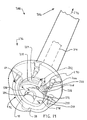
- extraction device 100 is shown.
- the extraction device 100 is utilized for removing the liner from the shell of an acetabular cup.
- the extraction device 100 includes a jaw 102 for cooperation with the liner 40 of the acetabular cup 32.
- the jaw 102 includes a portion 104 in the form of, for example, a tip for penetrating into the liner 40.
- the extractor device 100 further includes a handle 106 operably associated with the jaw 102.
- the handle 106 is adapted for gripping the extraction device 100.
- the extraction device 100 may, for example, include a frame 108 for supporting the handle 106.
- the frame 108 may include supports 110 for cooperation with distal face 64 of the shell 38.
- the supports 110 are used to support base 112 of the frame 108.
- a shaft 114 is rotatably supported along longitudinal axis 116 of the shaft 114.
- the jaw 102 is connected to the shaft 114.
- the jaw 102 may, as shown in FIG. 1, include a first jaw segment 118 and a second opposed jaw segment 120. It should be appreciated that a different number of jaws, for example 3 jaws, may be used.
- the jaw segments 118 and 120 may be penetrated into the liner 40 in any suitable fashion.
- the extraction device 100 further includes an actuator 122.
- the actuator 122 is used to actuate or move the jaw segments 118 and 120 into engagement with the liner 40.
- the extractor 122 as shown in FIG. 1, may be in the form of a tapered component.
- a conifrustical tapered component For example, a conifrustical tapered component.
- An external taper 123 may cooperate with an internal taper 124 formed from the first jaw component 118 and the second component 120.
- the shaft 114 may include a ring 126 extending from end 128 of the shaft 114. Guiding supports 130 may be connected to the ring 126 and serve to guide and support the first jaw segment 118 and the second jaw segment 120.
- the jaw segments 118 and 120 are contracted into the position as shown in phantom as first position 132. In position 132, the jaw segments 118 and 120 may enter the inner portion of the liner 40. After the jaw segments are positioned within the liner 40, the jaw segments 118 and 120 are expanded outwardly in the direction arrows 134 until the jaw segments 118 and 120 engage with the liner 40 in second position 136.
- the jaw segments 118 and 120 are advanced to the second position 136 by moving the shaft 114 of the actuator 122 in the direction of arrow 138.
- the movement of the shaft 114 of the actuator 122 in the direction of arrows 138 results in the first jaw segment 118 and the second jaw segment 120 moving in the direction of arrows 134 to engage with the liner 40.
- the shaft 114 continues to be advanced in the direction of arrow 138 until the liner 40 separates from the shell 38.
- the shaft 138 may be moved in the direction of arrow 138 simply by pulling upwardly on the t-portion 139 of the handle 106 of the direction of arrow 138. It should be appreciated, however, that the force required to extract the liner 40 may be such that a tool may be required to assist with the extraction device 100.
- the extraction device 100 may further include a nut 140 threadably secured to external threads 142 formed on the shaft 114.
- a wrench for example, torque wrench 144 may be used to advance the nut 140 in the direction opposite the arrow 138 such that the shaft 114 may move in the direction of arrow 138 with respect to the base 112 of the frame 108 of the extraction device 100.
- the jaw 118 includes portion 104 for penetrating the liner 40.
- the first jaw 118 may have any suitable shape.
- the jaw segment 118 may have parallel spaced apart faces 146.
- the jaw segment 118 may include the portion 104 for penetrating the liner 40.
- the jaw 118 may include a point or tip 148.
- the point or tip 148 may be defined by a height or thickness T.
- the tip 148 may, for example, be perpendicular to the face 146.
- An included angle ⁇ may extend from the point 146 to one of the parallel spaces 146 and to angled face 147.
- the angle ⁇ may be selected to provide for a sufficient penetration of the liner 40.
- the angle ⁇ may be, for example, 5° to 49°.
- the parallel surfaces 146 of the jaw segment 118 may be separated by a distance, for example, HJ.
- the jaw 118 may be designed such that the jaw 118 may penetrate the liner 140 a distance defined by HB or height of the penetration.
- the distance HB may be, for example, 10 to 20mm
- the distance HP may be, for example, 1 to 8 mm.
- the liner is shown as being pulled from the shell 38 progressively, utilizing the extraction device of the present invention.
- the locking ring 58 is shown in its installed position within the liner groove 60 and the shell groove 62.
- the outer edge 66 of the locking ring 58 is shown in position in contact with distal surface 68 of the shell groove 62.
- the liner 40 is shown advanced in the direction of arrow 70 with respect to the shell 38.
- the extracting device of the present invention is used to move the liner 40 in the direction of arrow 70.
- outer edge 66 of the locking ring 58 is forced against distal surface 68 of the shell groove 62 causing the locking ring 58 to rotate in the direction of arrow 72.
- the outer edge 66 of the locking ring 58 moves away from the distal surface 68 of the shell groove 62 and inwardly in the direction of arrow 74. Because the locking ring 58 is split, the locking ring 58 may move in the direction of arrow 74 as the locking ring 58 contacts the distal surface 68 of the shell groove 62.
- the liner 40 is shown advanced further in the direction of arrow 70 with respect to the shell 38.
- the outer edge 66 of the locking edge ring 58 continues to move inwardly in the direction of arrow 74 and continues to rotate in the direction of arrow 72.
- the outer edge 66 of the locking ring 58 moves to the point that the locking ring edge 66 is sufficiently in the direction of arrow 74 that the liner 40 and the locking ring 58 may be removed from the shell 38.
- Extraction device 200 like the extraction device 100 of FIG. 1, is utilized for removing, for example, liner 40 from the shell 38 of an acetabular cup 32.
- the extraction device 200 includes a jaw. For example, first jaw 218.
- the first jaw 218 cooperates with the liner 40.
- the first jaw 218 includes a portion 204 for penetrating the liner 40.
- the extraction device 200 further includes a handle 206, which is associated with the jaw 218.
- the handle 206 is adapted for gripping the extraction device 200.
- the extraction device 200 includes a base 208.
- the base 208 serves to support the supports or legs 210.
- a plurality of legs 210 may be used.
- six equally spaced apart legs 210 are used.
- the legs 210 may, as shown in FIG. 9, be adjustable radially to accommodate different sizes of acetabular cups.
- the base 208 includes a track 226 for permitting the legs to move radially in the direction of arrow 230.
- the extraction device 200 further includes a housing 228 for connecting the base 208 to the handle 206. It should be appreciated that the housing 228 may serve as part of the handle 206 as well.
- the housing 228 may have any suitable shape and may, for simplicity and as shown in FIG. 9, be of a generally hollow or tubular shape having a generally cylindrical outer diameter.
- the handle 206 is secured to the housing 228 and may, as shown in FIG. 9, includes a first handle t-portion 232 extending transversally from the housing 204.
- the handle 206 may likewise have a second handle t-portion 234 of the handle extending transversally from the housing 204 and opposed to the first handle t-portion 232.
- the extraction device 200 further includes a jaw assembly 236 for supporting and directing jaws 202 including the first jaw 218 and second jaw 220.
- the jaw assembly 236 further includes a protrusion 230 for assisting in actuating the first jaw 218 and the second jaw 220.
- the jaw actuator 238 as shown in FIG. 13, may include the protrusion 230.
- the protrusion 230 has a generally conifrustical shape and cooperates with tapered cavity 224 formed in jaw assembly 236.
- the protrusion 230 when advanced in the direction of arrow 240 causes the first jaw 218 and the second jaw 220 to move in the direction of arrows 242 to serve to cause the jaws 218 and 220 to penetrate into the liner 40.
- the jaw actuator 238 is used to actuate the jaw or to move the protrusion 230 in the direction of arrow 240.
- the jaw actuator 238 as shown in FIG. 13, may include a shaft 214 positioned within tubular housing 228.
- the shaft 214 may move in the direction of arrow 240 with respect to housing 228.
- the shaft 218 is connected to the protrusion 230 and is slidably fitted to the base aperture 244 of base 208.
- the shaft 214 is also slidably fitted within spool aperture 246 of spool 248.
- the shaft 214 is threadably secured to stem 250 of nut 256 positioned over the end 252 of the shaft 214. Internal threads 254 formed on nut 256 cooperate with external threads 255 formed on shaft 214.
- the nut 256 is rotatably connected to the spool 248. As the nut 256 is rotated in the direction of arrow 258, the shaft 214 is advanced in the direction of arrow 240 causing the jaws 218 and 220 to penetrate into the liner 40. the jaws first react with the spring until engagement with liner.
- the liner 40 is advanced in the direction of arrow 240.
- the jaw actuator 238 causes the jaws 218 and 230 to advance in the direction of arrow 240 with respect to the shell 38 and the frame 208.
- the jaws 218 and 220 thus move from first position 250 as shown in solid to second position 252 as shown in phantom.
- the jaws 218 and 220 arrive at the second position 252, as is shown in phantom, the liner 40 has separated from the shell 38.
- the jaws 218 and 220 may be advanced in the direction of arrow 240 in any suitable fashion.
- the jaw assembly 236 is fixably secured to the shaft 214.
- the shaft 214 is slidably secured to the base 208 at base aperture 244.
- the second end 252 of the shaft 214 is connected to the spool 248.
- the shaft 214 advances, similarly, in the direction of arrow 254.
- extraction mechanism 257 In order to advance the shaft 214 in the direction of arrow 254 to separate the liner 40 from shell 38, extraction mechanism 257 is used.
- the extraction mechanism 257 includes a spool 248, which includes external threads 258 formed on a portion thereof. External threads 258 cooperate with internal threads 260 formed on the inner periphery of the tubular housing 228.
- the spool 248 is thus threadably connected to the tubular housing 228.
- the extraction mechanism 257 further includes the first t-portion 232 of the handle 206.
- the first t-portion 232 is fixably connected and extends transversally from the spool 248.
- the extractor mechanism 257 further includes the second t-portion 234 of the handle 206.
- the second t-portion 234 extends transversally from the tubular housing 228.
- the surgeon utilizes one hand to hold the second t-portion 234 of the handle 206 and uses his second hand to grasp the first t-portion 232 of the handle 206.
- the spool 248 is rotated relative to the tubular housing 228. Since the spool 248 is threadably engaged with the tubular housing 228. As the tubular housing 228 rotates about the longitudinal centerline 216, the spool 248 is advanced in the direction of arrow 240 with respect to the tubular housing 228.
- the nut 256 is secured to the spool 248 and causes the nut 256 to likewise advance in the direction of arrow 240.
- the shaft 214 is threadably secured to the nut 256 such that the nut 256 advances in the direction of arrow 240.
- the shaft 214 likewise, advances in the direction of 240.
- the jaws 218 and 220 which are secured to the shaft 214, advance in the direction of arrow 240, removing the liner 40 from the shell 38.
- the jaw assembly 236 for use within the extractor device 200 of the present invention is shown.
- the jaw assembly 236 is shown in FIG. 14 may include a plurality of jaws, for example, first jaw 218 and second jaw 220.
- the jaws 218 and 220 are spaced apart and diametrically opposed.
- the jaws 218 and 220 include a portion 204 of the jaw for penetrating the liner.
- the jaws 218 and 220 as is shown in FIG. 14, are positioned between an inner plate 266 and an outer plate 268.
- the inner plate 266 and outer plate 268 may have any suitable shape and may, as shown in FIG. 16, be generally cylindrical.
- the inner plate 266 and outer plate 268 may be parallel to each other and may be spaced apart by columns 270.
- the columns 270 may be secured to the plates 266 and 268 by fasteners, for example, screws 272.
- the inner plate 266 may be slidably fitted to the shaft 214.
- the inner plate 266 and/or the shaft 214 may be slidably fitted to the frame 208.
- the shaft 214 may as shown in FIG. 14 be fixably secured to the actuator or conifrustical protrusion 230.
- the outer plate 268 may include an internal opening 274 to permit clearance of the protrusion 230 therewith.
- the protrusion 230 cooperates with tapered cavities 224 formed on the first jaw 218 and the second jaw 220. As the shaft 214 moves in the direction of arrow 276, the protrusion 222 likewise moves in the direction of 276 causing the first jaw 218 and the second jaw 220 to move in the direction of arrows 278.
- Extraction device 200 may be made of any suitable, durable material capable of sterilization by any commercially available sterilization technique.
- the extractor device and its components may be made of, for example, plastic, metal, a composite, or a ceramic.
- the extraction device 200 and its components may be made of a metal.
- Such metals may include a cobalt chromium alloy, stainless steel alloy, or a titanium alloy.
- Extraction device 300 of FIGS. 16 to 23 is similar to the extraction device 200 of FIGS. 13 to 15, except that the extraction device 300 uses a set of levers to both actuate the jaws and extract the liner from the shell.
- the extraction device 300 includes an extraction mechanism 356 that is both used to extract the liner from the shell as well as to actuate the jaws.
- the extraction device 300 includes a jaw assembly 336 which cooperates with cup 32 to extract the liner 40 from the shell 38.
- the jaw assembly 336 is operably connected to the extraction mechanism 356 by an actuator 314 in the form of a shaft.
- the extraction device 300 as shown in FIG. 16 includes a base 308 includes a support 310 for supporting face 64 of the shell 38.
- the base 308 also includes a hollow stem 370 extending in the direction opposed of that the support of 310.
- the extraction mechanism 356 further includes a tubular housing 328, which is fittably secured over the periphery of the hollow stem 370 of the base 308.
- the first t-portion 332 of handle 306 extends transversely from end 372 of the tubular housing 328.
- a second t-portion 334 extends transversally from end 372 of the tubular housing 328 and is opposed to the first t-portion 332.
- the actuator device 300 further includes actuator 314 in the form of a shaft.
- the actuator 314 slidably fits within central opening 374 of the tubular housing 328.
- the actuator 314 includes a head 375 located on first end 376 of the actuator 314.
- the jaw assembly 336 is connected to the actuator 314 at second end 378 of the actuator 314.
- the extraction mechanism 356 of the extraction device 300 includes a first lever 380 pivotally connected to handle 306 by first pin 382. Similarly, the extraction mechanism 356 further includes a second lever 384, which is pivotally connected to the handle 306 by second pin 386. As the first lever 380 is rotated in the direction of arrow 381, the first pawl 383 of the first lever 380 advances toward head 375. Similarly, as the second lever 384 is rotated in the direction of arrow 387, the second pawl 385 pushes against head 375. The levers 380 and 384 are rotated in the direction of arrow 381 and 387, respectively to advance pawls 383 and 385 respectively. The pawls 383 and 385 urge the head 385 in the direction of arrow 388 causing the jaws 302 to advance in the direction of arrow 390.
- the jaw assembly 336 includes a protrusion 322, which is fixably secured to second end 378 of the actuator 314.
- First jaw 318 and second jaw 320 are positioned transverse and opposed to the protrusion 322.
- Jaws 318 and 320 define a cavity 324, which cooperates with the protrusion 322 to advance the jaws 318 and 320 in the direction of arrows 390.
- 16A is missing
- the jaw assembly 336 defines a first position 391 in which the jaws are in their innermost or closest position to each other. At this position the extraction device 300 may be loaded into the acetabular cup 32.
- the first jaw 318 and the second jaw 320 are advanced into engagement with the liner 40 of the cup 32.
- the protrusion moves from first position 391 to second position 392 as shown in phantom.
- the jaws 318 and 320 are fully engaged with the liner 318.
- the protrusion 322 is advanced further in the direction of arrow 389 until the protrusion 322 is advanced to third position 393.
- the liner 40 has been separated from the shell 38 and the extraction device may along with the liner 40 may be removed from the shell 38 to complete the extraction of liner 40 from the shell 38.
- the hollow stem 370 and the bore 308 may be integral with each other.
- the bore 308 may be generally disc shaped with a hollow cylindrical support 310 extending from the bore 308.
- a spring 395 may be positioned below the bore 308 and contained by the shaft 314. The spring 395 is used to urge the jaw assembly 338 in a direction away from base 308.
- the jaws 318 and 320 may be generally rectangular with a portion 304, which is defined by a radius and is adapted for penetrations into the liner 40.
- the jaw assembly 336 includes jaw cradle 360, which includes jaw cradle bottom 361, which is fixably attached to the shaft 314.
- the jaw cradle 360 further includes the jaw cradle top 362.
- the jaw cradle bottom 361 is slidably fitted within the inner walls 363 of the jaw cradle top 362.
- the jaw cradle bottom 361 is partially aligned by a slidable fit of the shaft 314 to the jaw cradle top 362.
- the jaw assembly 336 is shown with the actuator 314 in symbolic black form.
- the actuator 314 is fixably secured to the jaw cradle bottom 361 or may be integral therewith.
- the first jaw 318 is contacted between the cradle top 362 and the cradle bottom 361.
- the second jaw 320 is cradled between the cradle top 362 and the cradle bottom 361.
- the first jaw 318 includes an incline surface 364 for cooperation with protrusion 322 of the jaw cradle bottom 361.
- the second jaw 320 includes an incline surface 366 for cooperation with the protrusion 322.
- the first jaw 318 as well as the second jaw 314 may be generally in the form of a rectangular solid.
- the jaws for the extraction device of the present invention may have other shapes, particularly shapes more in conformance with the hemispherical shape of a typical liner.
- the jaws 318A and 320A may be in the form of a semi-cylinder.
- the jaw 318A may include a planar face 370A while the second jaw 320A may include a planar face 371A, which mates against the planar surface 370A of the first jaw 318A to mate with a generally cylindrically shaped pair of jaws.
- the jaws 318A and 320A combine to define a radius RC and a length LC.
- the jaws for an extraction device of the present invention may likewise be that of a truncated sphere. Perhaps the truncated sphere may be truncated at the opposing poles of the sphere.
- the extraction device may include a first jaw 318B and a second jaw 320B.
- the first jaw 318B may include a planar face 370B, which mates with planar face 371B of the second jaw 320B.
- the first and the second jaw, 318B and 320B combine to form a truncated sphere defined by a radius RS and a height HS.
- the extraction device of the present invention may use a number of alternate structures to actuate the opposed jaws into engagement with the liner.
- FIG.23C another embodiment of the present invention is shown as extraction device 300C in which the opposing jaws 318C and 320C are operably connected by a series of two levers 340C and 342C. The forces applied between the adjacent levers 340C and 342C such that the jaws 318C and 320C are moved in opposed directions to engage in the liner 40.
- FIG. 23D Yet another embodiment of the present invention in FIG. 23D is shown as extracting device 300 that utilizes yet another mechanism for advancing the jaws into the liner.
- mechanism 356D is in the form of a scotch yoke-type mechanism in which the first jaw 318D and the second jaw 320D include elongated slots 350D diagonally placed on the jaws 318D and 320D.
- An actuator including a series of pins 352D cooperate with the slots 350D to advance the jaws 318D and 320D in opposed directions to engage into the liner 40.
- the device 300E includes mechanism 356E in the form of cam 322E that rotatably advances jaws 318E and 320F to engage liner 40.
- the device 300F includes rack and pinion mechanism 356F including a first rack 322F formed on first jaw 318F and a second rack 323F formed on a second jaw 320F.
- the jaws 318F and 320F are actuated by pinion 325F extending from shaft 314F and cooperating with the racks 322F and 323F to advance jaws 318F and 320F to engage liner 40.
- FIGS. 25 and 26 another embodiment of the present invention is shown as extraction device 400.
- the extraction device 400 is different than the extraction device 300 of FIG. 16 or the extraction device 200 of FIG. 13.
- the extraction device 400 includes an extraction mechanism 456 different than the extraction mechanism 256 of the extraction device 200 of FIG. 13.
- the device 400 includes a jaw actuator 438 different than the jaw actuator 238 of the extraction device 200 of FIG. 13.
- the extraction mechanism 456 of the extraction device 400 utilizes an extraction cam 475 while the jaw actuator 438 utilizes an actuator cam 422.
- the actuator cam 422 and extraction cam 475 represent different mechanisms to extract and to actuate than the previous identified extraction devices of the present invention.
- the extraction device 400 includes a base 408.
- a support 410 extends from the base 408.
- the support 410 is utilized to support shell 38 of the hip cup 32 at shell face 64.
- Tubular housing 428 extends from base 408 in a direction opposed to support 410.
- a handle 406 extends from housing 428 or may be integral with the tubular housing 428.
- the handle 406 includes a transverse first t-portion 432 extending transversally from the tubular housing 428.
- the handle 406 further includes a transverse second t-portion 434 extending transversally from the tubular housing 428 and opposed to the first t-portion 432.
- An actuator or shaft 414 is slidably and rotatably fitted within the tubular housing 428.
- the extractor device 400 further includes the lever 484 connected to first end 476 of the shaft 414.
- the extractor device 400 further includes the cam 422 connected to second end 478 of the shaft 414.
- the extractor device 400 further includes a jaw assembly 436 operably connected to the cam 422 of the shaft 414.
- the jaw assembly 436 includes first jaw 418 and second jaw 420.
- the jaws 418 and 420 are used to cooperate with liner 40 of the hip cup 32.
- the jaw actuator 438 of the extraction device 400 includes a jaw assembly 436.
- the jaw assembly 436 includes the first jaw 418 and the second jaw 420.
- the jaws 418 and 420 include an arcuate inner periphery 421, which cooperates with cam 422 mounted on shaft 414. As the shaft 414 rotates in the direction of arrow 486, the cam 422, which is mounted to the shaft 414, likewise rotates in the direction of arrow 486.
- the extraction mechanism 456 is shown in greater detail.
- the extraction mechanism 456 is utilized not only to extract the liner 40 from shell 38, but is also used to transmit force to the jaw actuator 438.
- the extraction mechanism 456 includes lever 484 which is pivotally connected to shaft 414 by pin 482.
- Handle 406 includes a recess 407 about which cam 475 of the lever 484 may rotate about longitudinal axis 473 of the shaft 414.
- the cam 475 may be integral with the lever 484.
- the cam 475 is, as shown in FIG. 26, an eccentric cam.
- the cam 475 defines a cam centerline 477 that is spaced from the pin 482 such that the lever 484 is rotated the cam 475 asserting a force along the longitudinal axis 473.
- the lever 484 and the handle 406 may be adapted to prevent the lever 484 from rotating in the direction of arrow 486. Such rotation would cause the lever 484 and the shaft 414 to rotate about centerline 473 with respect to the handle 406. As the lever 484 is rotated in the direction of arrow 486, the cam 422 likewise rotates in the direction of arrow 486. The first jaw 418 and the second jaw 420 thus move in the direction of arrows 471 causing the jaws 418 and 420 to penetrate the liner 40.
- the lever 484 is rotated about the centerline 473 of the extraction device 400 from first position 481 of the lever 484 as shown in solid to second position 483 of the lever 484 as shown in dash line 483.
- the lever 484 is in the second position 483, the jaws 418 and 420 have engaged with the liner 484.
- the lever 484 is advanced in the direction of arrow 487 from second position 483 to third position 485 as shown in phantom.
- the handle 406 moves in a single motion for single purpose; to engage jaws 418 and 420 and liner 40. Once engaged, the T-handle 406 is rotated to remove liner 40.
- the jaws 418 and 420 may have any suitable shape capable of penetrating the liner 40.
- the jaws 418 and 420 may include a plurality of spaced apart ribs 441.
- the ribs 441 may extend substantially along periphery 443 of the jaws 418 and 420.
- the jaws 418 and 420 may include, for example, 2, 3, 4 or 5 spaced apart ribs 481.
- the extraction device of the present invention may be in the form of extraction device 400B having first and second jaws 418B and 420B.
- the jaws 418B and 420B may be similar to the jaws 418 and 420 of the extraction device 400 except that instead of having the ribs 441 of the extraction device 400, the extraction device 400B may include nibs or knurls 441B formed on periphery 443B of the jaws 418B and 420B.
- the jaw assembly 436 of the extraction device 400 includes first jaw 418.
- the first jaw 418 includes a plurality of spaced apart ribs 441.
- the ribs 441 include a point 448 for penetration into liner 40 of the acetabular cup 32.
- the points 448 may be slightly flat, flattened, have a radius, or have an essentially sharp point.
- the ribs 441 may include a plurality of ribs such as two ribs, three ribs, four ribs, or five ribs or more.
- the ribs 441 may be equally spaced about periphery 443 of the jaw 418.
- the first jaw 418 is shown in cooperation with second jaw 420 to form jaw assembly 436.
- the jaws 418 and 420 include inner periphery 421 for cooperation with the cam 422.
- the jaws 418 and 420 include the ribs 441 for penetration into the liner 40.
- the jaw assembly 436 is shown with the jaws 418 and 420 in cooperation with the cam 422.
- the first jaw 418 and 420 are shown in first position 491 as shown in solid when the jaws 418 and 420 are in their most adjacent position. In this most adjacent position, the jaw assembly 236 and the extraction device 400 may be inserted into the acetabular cup 32.
- the jaw assembly 436 is also shown with the jaws 418 and second jaw 420 in second position 493 as shown in phantom.
- the cam 422 is rotated in the direction of arrow 489 approximately 90° such that the cam 422 engages inner periphery 421 of the jaws 418 and 420.
- the jaws then expand outwardly in the direction of arrows 471 such that ribs 441 of the jaws 418 and 420 penetrate liner 40.
- extraction device 500 yet another embodiment of the present invention is shown as extraction device 500.
- the extraction device 500 of FIG. 30 is similar to the extraction device 400 of FIGS. 24-29.
- the extraction device 500 however includes a cam 575, which is somewhat different than the cam 475 of the extraction device 400.
- the cam 575 of the extraction device 500 has a periphery that is elliptical or oval rather than circular.
- the extraction device 500 includes a shaft 514 that is used to cause the jaws to expand into the liner and to cause the liner to be extracted from the shell.
- the shaft 514 permitted to rotated in the direction of arrow 586 and translate in the direction of arrow 588 within the body 528 of handle 506.
- Lever 584 is pivotally connected to the handle 506 about pin 582.
- the cam 575 defines a periphery 577 thereof, which is in sliding contact with end 576 of the shaft 514.
- the shaft 514 may have a swivel joint that allows the shaft to rotate during extraction of liner.
- the shaft 514 may likewise rotate in the direction of arrow 586 to actuate a cam similar to the cam 422 of the extractor device 400 of FIG. 26.
- the link 589 connected to the lever 584 and the shaft 514 causes the shaft 514 to advance upwardly in the direction of arrow 588 to engage jaws with liner.
- the T-handle is then rotated to produce axial force to remove liner 40.
- kit 600 includes cup 32 including liner 40, shell 38, and snap ring 58 fitted between the liner 40 and the shell 38 for securing the liner 40 to the shell 38.
- the kit 600 further includes an extraction device 400.
- the extraction device 400 further includes base 408, handle 406 extending from the base 408, and jaws 436 operably connected to the base 408.
- the method 700 includes a first step 710 of inspecting an implanted acetabular cup assembly including a shell and a polymer liner in vivo in the patient.
- the method 700 further includes a second step 712 of determine if the polymer liner should be replaced from the shell of the acetabular cup assembly.
- the method 700 further includes a third step 706 of providing an extraction device for removing the liner from the shell.
- the extraction device includes a jaw for cooperation with the liner.
- the jaw includes a portion of the jaw for penetrating into the liner.
- the extraction device also includes a handle operably associated with the jaw. The handle is adapted for gripping the extraction device.
- the method 700 further includes a fourth step 716 of extracting the liner from the shell with the extraction device while the shell is still implanted in the patient.
- the method 800 includes a first step 810 of inspecting an implanted acetabular cup assembly including a shell, a polymer lining, and a snap ring in vivo in a patient.
- the method 800 further includes a second step 812 of determining if the polymer liner should be replaced from the shell of the acetabular cup assembly.
- the method 800 further includes a third step 814 of providing a distraction device for removing the liner from the shell.
- the extraction device includes a jaw for cooperation with the liner.
- the method 800 further includes a fourth step 816 of extracting the liner and the snap ring from the shell simultaneously with the extraction device while the shell is still implanted in the patient.
Landscapes
- Health & Medical Sciences (AREA)
- Transplantation (AREA)
- Orthopedic Medicine & Surgery (AREA)
- Heart & Thoracic Surgery (AREA)
- Life Sciences & Earth Sciences (AREA)
- Oral & Maxillofacial Surgery (AREA)
- Engineering & Computer Science (AREA)
- Biomedical Technology (AREA)
- Physical Education & Sports Medicine (AREA)
- Vascular Medicine (AREA)
- Cardiology (AREA)
- Animal Behavior & Ethology (AREA)
- General Health & Medical Sciences (AREA)
- Public Health (AREA)
- Veterinary Medicine (AREA)
- Prostheses (AREA)
- Surgical Instruments (AREA)
Abstract
Description
- The present invention relates generally to the field of orthopaedics, and more particularly, to an instrument for use in arthroplasty.
- A joint within the human body forms a juncture between two or more bones or other skeletal parts. The ankle, hip, knee, shoulder, elbow and wrist are just a few examples of the multitude of joints found within the body. As should be apparent from the above list of examples of joints, many of the joints permit relative motion between the bones. For example, the motion of sliding, gliding, and hinge or ball and socket movements may be incorporated into a joint. For example, the ankle permits a hinge movement, the knee allows for a combination of gliding and hinge movements and the shoulder and hip permit movement through a ball and socket arrangement.
- The joints in the body are stressed or can be damaged in a variety of ways. For example, the gradual wear and tear is imposed on the joints through the continuous use of a joint over the years. The joints that permit motion have cartilage positioned between the bones providing lubrication to the motion and also absorbing some of the forces direct to the joint. Over time, the normal use of a joint may wear down the cartilage and bring the moving bones in a direct contact with each other. In contrast, in normal use, a trauma to a joint, such as the delivery of a large force, from an accident for, example, an automobile accident, may cause considerable damage to the bones, the cartilage or to other connective tissue such as tendons or ligaments.
- Arthropathy, a term referring to a disease of the joint, is another way in which a joint may become damaged. Perhaps the known joint disease is arthritis, which is generally referred to a disease or inflammation of a joint that results in pain, swelling, stiffness, instability, and often deformity.
- There are many different forms of arthritis, with osteoarthritis being the most common and resulting from the wear and tear of a cartilage within a joint. Another type of arthritis is osteonecrosis, which is caused by the death of a part of the bone due to loss of blood supply. Other types of arthritis are caused by trauma to the joint while others, such as rheumatoid arthritis, Lupus, and psoriatic arthritis destroy cartilage and are associated with the inflammation of the joint lining.
- The hip joint is one of the joints that is commonly afflicted with arthropathy. The hip joint is a ball and socket joint that joins the femur or thighbone with the pelvis. The pelvis has a semispherical socket called the acetabulum for receiving a ball socket head in the femur. Both the head of the femur and the acetabulum are coated with cartilage for allowing the femur to move easily within the pelvis. Other joints commonly afflicted with arthropathy include the spine, knee, shoulder, carpals, metacarpals, and phalanges of the hand. Arthroplasty as opposed to arthropathy commonly refers to the making of an artificial joint. In severe cases of arthritis or other forms of arthropathy, such as when pain is overwhelming or when a joint has a limited range of mobility, a partial or total replacement of the joint within an artificial joint may be justified. The procedure for replacing the joint varies, of course, with the particular joint in question, but in general involves replacing a terminal portion of an afflicted bone with a prosthetic implant and inserting a member to serve as a substitute for the cartilage.
- The prosthetic implant is formed of a rigid material that becomes bonded with the bone and provides strength and rigidity to the joint and the cartilage substitute members chosen to provide lubrication to the joint and to absorb some of the compressive forces. Suitable material for the implant include metals, ceramics, composites and metals, for example, a titanium alloy, a cobalt chromium alloy, and a stainless steel alloy. Suitable materials for cartilage substitutes include polyethylene. A cement may also be used to secure the prosthetic implant to the host bone.
- A total hip replacement, for example, involves removing the ball shaped head of the femur and inserting a stem implant into the centre of the bone, which is referred to as the medullary canal, or marrow of the bone. The stem implant may be cemented into the medullary canal or may have a porous coated surface for allowing the bone to heal directly to the implant.
- The stem implant has a neck and a ball shaped head, which are intended to perform the same functions as a healthy femur's neck and a ball shaped head. The polyethylene cup is inserted into the acetabulum and has a socket for receiving the head on the stem implant.
- The invention relates to a surgical instrument for releasing the press fit of a joint insert in a joint socket.
- Joint inserts are often held by a cone-type press fit in joint sockets, for example, in hip joint sockets. In order to release such joint inserts from the joint socket again, it is either necessary to destroy the joint inserts or to provide special devices on the joint socket which enable ejection of the joint insert from the joint socket. For example,
DE-U-29516473 discloses a screw arrangement on the joint socket with which the joint insert can be pressed out of the joint socket. However, this makes it necessary for the joint socket to be of appropriate design and for an opening to be left in the joint insert. - An acetabular hip prosthesis has various design alternatives within their design and construction. One such design alternative has to do with whether the hip prosthesis is constrained or unconstrained. Similarly, a hip prosthesis, including a ball attached to a stem, is inserted into the canal of the resected femur and a socket including a portion of a spherical pocket is secured to the acetabulum. The portion of the ball in contact with the acetabular liner may represent less than 50% or a hemisphere of the head. In such an arrangement the head may freely be positioned in the liner. Alternatively, the acetabular component may extend around the head of the femur for an amount greater than 180°. In such a configuration the head may not freely be removed from the acetabular component. Such a construction is defined as a constrained prosthesis.
- Referring now to FIG. 3, a prior art unconstrained prosthesis is shown as prosthesis 10. The prosthesis 10 includes a
stem 12 and ahead 14. Thestem 14 is placed withinfemur 2. Thehead 14 matingly fits withliner 16, which is fitted withincup 18. Thecup 18 is secured toacetabulum 4 of the patient. Theliner 16 and thehead 14 define a contact area between them having an included angle β, which is less 180°. Since β is less than 180°, thehead 14 may freely move in and out of theliner 16. - It should be appreciated that use of an unconstrained liner may make a dislocation of the hip possible for the patient. If excessive extension of the leg is made by the patient, the
head 14 may slip from theliner 14 and a dislocation or a misplacement of thehead 14 may occur. If a dislocation has occurred, discomfort may accompany such dislocation and a surgical procedure to relocate the hip may be necessary. - The unconstrained hip prosthesis 10 as shown in FIG. 3, does however have the advantage of increased range of motion. The range of motion of the hip prosthesis 10 may be defined by an angle α and θ that represents the motion between the
hip stem 12 and theliner 16 that can occur. - To avoid problems of dislocation of the head of the femur, prostheses have been provide for increased anglar contact between the liner and the head of the prosthesis. Such prosthesis are called constrained prosthesis. Constrained prosthesis prevent the occurrence of dislocation of the head of the prosthesis.
- Referring now to FIG. 4, a constrained prosthesis 10' is shown. The prosthesis 10' includes a stem 12' similar to the stem in FIG. 3. The stem 12' has a head 14' secured thereto. The
head 14 may be similar to the head 14' OF FIG.3. The prosthesis 10' further includes acap 18 to which a liner 16' is secured. The cap 18' is secured toacetabulum 4 of the patient. The stem 12' is secured tofemur 2 of the patient similarly. - The
liner 16 is somewhat different than theliner 16 of the prosthesis 10 of FIG. 3. The liner 16' is a constrained liner. In other words, the liner 16' contacts the head 14' of the prosthesis 10' at a contact angle θ' which is greater than 180°. Since the contact angle between the head 14' and liner 16' is greater than 180°, the dislocation of the hip prosthesis 10' is much less likely. - The head 14' may be placed in the liner 16' utilizing different techniques. For example, the liner 16' may include a series of slits in the distal end thereof, which permit the distal portion of the liner 16' to open until the head 14' is assembled. After the head 14' is assembled into the liner 16', a constraining ring 20' may be positioned on the liner 16'.
- To prevent the liner 16' from being separated from the cap 18', the liner 16' may include an additional feature to secure the liner 16' to the cap 18'. For example, the cap and liner may include grooves 22' and 24' respectively, for receiving a snap ring 26' to be secured there between.
- During revision surgery it may be necessary for a liner Δ to be removed from the prosthesis and be replaced with a new liner. The cap and stem may remain in the patient. The liner, thus, may need to be removed from the cap.
- To remove a liner from the cap of an unconstrained prosthesis 10 as shown in FIG. 3, various devices are available for removing the liner. For example, a suction cup may be utilized to remove the liner from the cap or the liner may simply fall out in that it is not permanently secured to the
cap 18. Alternatively, a screw 28 may be utilized to separate the liner from the cap as shown inUS-5282864 . - The removal of a liner from the constrained prosthesis 10' of FIG. 4 is more difficult. The snap ring makes the removal of the constrained liner 16' quite troublesome.
- Attempts have been made to remove the locking ring from the grooves of the liner and shell by contracting the locking ring and then lifting the liner from the shell. Attempts of contracting the locking ring have proved unsuccessful because the locking ring may be inaccessible and difficult to compress in situ with the prosthesis in the patient.
- Another attempt at removing the locking ring, including driving screws through the liner in hopes that the locking mechanism would break and lift the liner from the shell. The reaction force of the screw and the shells may be sufficient to overcome the force of the locking mechanism.
- Another attempt to remove the liner from the shell was to cut the liner from the shell. Tools that are designed to cut liners may not be deep enough to expose the locking ring. Also, the use of a tool to cut the liner may raise concerns of creating polyethylene debris in the incision, which may prove to be problematic in that such debris may contribute to osteolysis.
- This invention provides a surgical instrument for removing the liner from the shell in situ in a patient where the forces necessary to separate the liner from the shell may be quite large.
- The instrument of the present invention can be used to contract the locking ring and cause it to buckle or rotate such that the liner may be lifted out of the shell. The instrument of the present invention accomplishes the contracting and buckling of the locking ring by laterally expanding with a gripping device in the liner and lifting the liner out of the shell with sufficient force to cause the locking ring to buckle and collapse.
- The device in the form of an instrument of the present is inserted into a liner and a gripping mechanism in the form of, for example, teeth that are expanded laterally into the polyethylene liner to hold the removal tool in place. Once the griping mechanism is in place, expanded into the polyethylene liner and axial tension force is applied, the force applied via a mechanism, for example, a screw or a cam-lever mechanism, causing the locking ring to buckle and collapse. The ring collapses into a position such that the locking ring may pass by the groove of the shell and permit the lifting of the liner from the shell.
- Accordingly, in one aspect, the invention provides an extraction device for removing a liner from an acetabular cup. The extraction device includes a jaw and a handle. The jaw is for cooperation with the liner and including a portion of the jaw for penetrating into the liner. The handle is operably associated with the jaw and is adapted for gripping the extraction device.
- In another aspect, the invention provides an extraction device for removing a liner and a snap ring simultaneously from an acetabular cup. The liner is fitted into an inner periphery of the cup and the snap ring is fitted into a groove in the inner periphery of the cup. The extraction device includes a jaw and a handle. The jaw is for cooperation with the liner and includes a portion of the jaw for penetrating into the liner. The handle is operably associated with the jaw and is adapted for gripping the extraction device. The handle and the jaw are adapted to provide sufficient penetration of the jaw into the liner to permit the snap ring to be buckled out of the groove and removed simultaneously with the liner.
- In a further aspect, the invention provides an extraction device for removing a liner from an acetabular cup. The extraction device includes a body and an actuator. The actuator is operably connected to the body. The extraction device also includes a jaw for cooperation with the liner. The jaw includes a portion of the jaw for penetrating into the liner. The jaw is operably connected to the actuator. The actuator is adapted to cooperate with the jaw to provide a first position for the jaw spaced from the liner and a second position for the jaw in contact with the liner.
- In yet another aspect, the invention provides a kit for use in revision hip surgery. The kit includes an extraction device for removing a liner from an acetabular cup. The extraction device includes a jaw for cooperation with the liner. The jaw includes a portion of the jaw for penetrating into the liner. The extraction device also includes a handle operably associated with the jaw. The handle is adapted for gripping the extraction device. The kit also includes a polymer revision cup and a snap ring.
- In a further aspect, the invention provides a cup assembly including a metal shell having an internal groove and a polymer liner fitted into the shell. The cup assembly also includes a snap ring fitted into the shell. At least the shell, the liner or the snap ring or more than one are adapted to permit the snap ring to be removed from the shell simultaneously with the polymer liner.
- The instruments provided by the invention can be used in a method for performing orthopaedic revision surgery. The method includes the steps of inspecting an implanted acetabular cup assembly including a shell and a polymer liner in vivo in a patient and determining if the polymer liner should be replaced from the shell of the acetabular cup assembly. The method also includes the step of providing an extraction device for removing the liner from the shell. The extraction device includes a jaw for cooperation with the liner. The jaw includes a portion of the jaw for penetrating into the liner. The extraction device also includes a handle operably associated with the jaw. The handle is adapted for gripping the extraction device. The method also includes the step of extracting the liner from the shell with the extraction device while the shell is still implanted in the patient.
- The instruments provided by the invention can be used in a method for performing orthopaedic revision surgery. The method includes the steps of inspecting an implanted acetabular cup assembly including a shell, a polymer liner and a snap ring in vivo in a patient and determining if the polymer liner should be replaced from the shell of the acetabular cup assembly. The method also includes the step of providing an extraction device for removing the liner from the shell. The extraction device includes a jaw for cooperation with the liner. The method also includes the step of extracting the liner and the snap ring from the shell simultaneously with the extraction device while the shell is still implanted in the patient.
- The technical advantages of the present invention include the ability to remove the liner without disabling of the locking mechanism. For example, according to one aspect of the present invention an extraction device for removing a liner for an acetabular cup is provided where in the acetabular cup includes a retaining ring to retain the liner to the cup. The extraction device includes a jaw that cooperates with a liner. The jaw includes a portion for penetrating into the liner. The extraction device further includes a handle connected to a jaw for gripping with the distraction device. Thus, the present invention provides for an ability to remove the liner without the disabling the locking mechanism.
- The technical advantages of the present invention further include the ability to remove the liner without creating polyethylene debris. For example and according to another aspect of the present invention, an extraction device is provided for removing a liner from an acetabular cup. The liner includes a locking ring, a jaw for cooperation with the liner, and a handle associated with the jaw. The jaw penetrates the liner and then the handle is used to grip the distraction device and pull the liner from the cup. The jaw engages the liner with sufficient depth such that the jaw has enough force transferring capacity to permit the locking ring to twist and contract such that the locking ring and liner may be pulled from the acetabular cup. Thus, the present invention provides for an ability to remove the liner without creating polyethylene debris.
- The technical advantages of the present invention further include the ability to remove the liner from a cup having a locking ring in one step. For example, according to yet another aspect of the present invention, an extraction device is provided for removing a liner from a cup having a retaining ring. The device includes a jaw for penetrating the liner and a handle connected to the jaw. The handle is used to pull the liner from the cup. Thus, the present invention provides for the ability to remove the liner from the cup in one step.
- The technical advantages of the present invention, further include quick and easy removal of a liner from an acetabular cup when the cup and liner are connected with a retaining ring. For example, according to another aspect of the present invention, a method for performing a hip arthroplasty includes a step in which the extraction device is provided with a jaw and a handle. The jaw is penetrated into the liner. The handle, which is connected to the jaw, is used to pull the liner from the cup. The force of liner being pulled from the cup causes the retaining ring to buckle progress inwardly such that the liner and retaining ring may be extracted from the cup. Thus, the present invention provides for a quick and easy method for removing a liner from a cup having a retaining ring.
- The technical advantages of the present invention further include the ability to provide an extraction device for removing a liner from an acetabular cup that is easy to manufacture. For example, according to one aspect of the present invention, an extraction device for removing a liner from a cup includes a jaw having a portion for penetrating the liner and a handle associated with the jaw. Thus, the present invention provides for an extraction device that is easy to manufacture and has few moving parts.
- The technical advantages of the present invention further include the ability to easily clean and sterilize the extraction device. For example, according to yet another aspect of the present invention, an extraction device is provided with a jaw for cooperation with a separable body and a handle removably connected to the body. Thus, the present invention provides for an extraction device with an ability to easily clean and sterilize the extraction device.
- Embodiments of the invention will now be described by way of example with reference to the accompanying drawings, in which:
- FIG. 1 is a plan view, partially in cross-section, of an acetabular liner extraction device in accordance to the present invention;
- FIG.1A is a portion plan view of the device of FIG. 1 showing the articulation in greater detail;
- FIG.2 is a partial plan view of the jaw of the device of FIG. 1'.
- FIG.3 is a plan view of a prior art unconstrained hip prosthesis;
- FIG.4 is a plan view of a prior art constrained hip prosthesis;
- FIG. 5 is a plan view, partially in cross-section, of a constrained hip prosthesis for use with the extraction device of the present invention;
- FIG. 6 is a partial view, partially in cross-section of the ring engaged in the prosthesis of FIG. 5;
- FIG. 7 is a partial plan view, partially in cross-section of the ring of FIG. 6 partially deflected;
- FIG. 8 is a partial plan view, partially in cross-section of the ring of FIG. 6 fully deflected;
- FIG. 9 is a perspective view of an acetabular liner extraction device in accordance with another embodiment of the present invention;
- FIG. 9A is a partial bottom view of the device of FIG. 9;
- FIG. 10 is another perspective view of the acetabular liner extraction device of FIG. 9;
- FIG. 11 is a plan view, partially in cross section of the acetabular liner extraction device of FIG. 9;
- FIG. 12 is another perspective view of the device of FIG. 9;
- FIG. 13 is a plan view, partially in cross section, of the acetabular liner extraction device of FIG. 9;
- FIG. 13A is a partial plan view, partially in cross-section of FIG. 13;
- FIG. 14 is a partial perspective view, partially in cross section, of the acetabular liner extraction device of FIG. 9;
- FIG. 15 is a plan view, partially in cross section, of the acetabular liner extraction device of FIG. 9;
- FIG. 16 is a plan view, partially in cross-section of an of an acetabular liner extraction device according to another embodiment of the present invention;
- FIG. 16A is a partial plan view, partially in cross-section of the jaws of the acetabular liner extraction device of FIG. 16;
- FIG. 16B is a partial plan view of the jaws of the device of FIG. 16;
- FIG. 17 is a perspective view of the shell support portion of the acetabular liner extraction device of FIG. 16;
- FIG. 18 is a plan view, partially in cross-section of the shell support portion of FIG. 17 of the acetabular liner extraction device of FIG. 16;
- FIG. 19 is a perspective view of the jaws for use with the device of FIG. 16;
- FIG. 20 is a plan view of the jaw of FIG. 19;
- FIG. 21 is a perspective view of the jaw cradle of the device of FIG. 16;
- FIG. 22 is an end view of the jaw cradle of the device of FIG. 16;
- FIG. 23 is a graphic model of the device of FIG. 16;
- FIG. 23A is a partial plan view of another embodiment of the device of the present invention;
- FIG. 23B is a partial plan view of another embodiment of the device of the present invention;
- FIG. 23C is a partial plan view of another embodiment of the device of the present invention;
- FIG. 23D is a partial plan view of another embodiment of the device of the present invention;
- FIG. 23E is a partial plan view of another embodiment of the device of the present invention;
- FIG. 23F is a partial plan view of another embodiment of the device of the present invention;
- FIG. 24 is a plan view, partially in cross-section, of another acetabular liner extraction device in accordance with another embodiment of the present invention;
- FIG. 25 is a bottom view of the jaws of the acetabular liner extraction device of FIG. 15;
- FIG. 26 is a plan view, partially in cross section, of yet another acetabular liner extraction device in accordance with yet another embodiment of the present invention;
- FIG. 26A is a partial plan view of the jaws of the device of FIG. 26;
- FIG. 26B is a partial plan view of the jaws of yet another device according to the present invention;
- FIG. 27 is an enlarged plan view of the jaws of the acetabular liner extraction device of FIG. 26;
- FIG. 28 is a partial enlarged plan view of the jaws of the acetabular liner extraction device of FIG. 26;
- FIG. 29 is a bottom view of the jaws of the device of FIG. 26;
- FIG. 30 is plan view, partially in cross section, of an acetabular liner extraction device according to another embodiment of the present invention;
- FIG. 31 is a plan view of a kit for performing hip arthroplasty according to the present invention;
- FIG. 32 is a flow chart of a method for performing hip arthroplasty in accordance with an embodiment of the present invention; and
- FIG. 33 is a flow chart of a method for performing hip arthroplasty in accordance with another embodiment of the present invention.
- Referring to the drawings, FIG. 5 shows a
prosthesis 30 for use with the extraction device of the present invention. Thehip prosthesis 30 includes anacetabular cup 32, ahead 34, connected to theacetabular cup 32, and astem 36, fixably attached to thehead 34. Theacetabular cup 32 is fixably secured toacetabulum 4 while thestem 36 is fixably attached tofemur 2. - The
acetabular cup 32 includes ashell 38, which is fixably attached to theacetabulum 4 and aliner 40, which is secured to theshell 38. Theshell 38 may be made of any suitable, durable material and may, for example, be made of a metal, a plastic, or a ceramic material. Theliner 40 may be made of any suitable, durable material for example, a metal, a plastic, a ceramic. To conform to the characteristics of human cartilage, theliner 40 may be made of a polymer for example, a cross-linked ultra-high molecular weight polyethylene as disclosed inUS-6228900 and used in products sold by DePuy Orthopaedics Inc under the trade mark Marathon. - The
acetabular cup 32 of FIG. 6 is utilized as part of aconstrained hip prosthesis 30. A constrained prosthesis is utilized to avoid dislocation of a hip joint for a patient. A constrained hip joint, such as aprosthesis 30 includesliner 40 having a hit contact periphery 42 that extents to angle α aboutspherical head 34. The angle α is greater than 180° so that thehead 34 is constrained within theliner 40. - As shown in FIG. 6, the
head 34 may be fitted intoliner 40 by proving theliner 40 with slits 44 cut through the cross-section of theliner 40. The slit 44 may include a plurality of equally spaced slits. The slits 44 permit theliner 40 to expand from theposition 46 in solid as shown to an expandedposition 48 as shown in phantom. - When the
head 34 is inserted and seated against the liner inner periphery 42, theliner 40 returns back tofirst position 46. When infirst portion 46band 50 is applied to groove 52 in theliner 40 and thehead 34 is contained in theliner 40. - The
liner 40 may be secured to shell 38 in any suitable manner. The present invention may be used to remove a liner from a shell independent of the manner, which the liner is secured to the shell. Theliner 40 may be secured to theshell 38, for example, in the manner as shown in FIG. 5. Theliner 40 may be secured by two distinct connecting mechanisms. For example, and as shown in FIG. 5, theshell 38 may include a taperedinner periphery 54 which mates with tapered external surface 56 ofliner 40. - In addition to the taper lock, the
hip prosthesis 30 of FIG. 5 may include a split or lockingring 58, which is fitted inliner groove 60 andshell groove 62. The lockingring 58 may be solid or split. Thering 58 is expanded to fit into theliner groove 60, and is compressed into theliner groove 60 so that the locking ring may fit into the inner periphery of the shell and thereby lock into theshell groove 62. - According to the present invention and referring now to FIG. 1,
extraction device 100, according to the present invention, is shown. Theextraction device 100 is utilized for removing the liner from the shell of an acetabular cup. Theextraction device 100 includes ajaw 102 for cooperation with theliner 40 of theacetabular cup 32. Thejaw 102 includes aportion 104 in the form of, for example, a tip for penetrating into theliner 40. Theextractor device 100 further includes a handle 106 operably associated with thejaw 102. The handle 106 is adapted for gripping theextraction device 100. - The
extraction device 100 may, for example, include aframe 108 for supporting the handle 106. Theframe 108 may includesupports 110 for cooperation withdistal face 64 of theshell 38. Thesupports 110 are used to supportbase 112 of theframe 108. Ashaft 114 is rotatably supported along longitudinal axis 116 of theshaft 114. - As shown in FIG. 1, the
jaw 102 is connected to theshaft 114. Thejaw 102 may, as shown in FIG. 1, include afirst jaw segment 118 and a secondopposed jaw segment 120. It should be appreciated that a different number of jaws, for example 3 jaws, may be used. Thejaw segments liner 40 in any suitable fashion. For example and is shown in FIG. 1, theextraction device 100 further includes anactuator 122. - The
actuator 122 is used to actuate or move thejaw segments liner 40. Theextractor 122 as shown in FIG. 1, may be in the form of a tapered component. For example, a conifrustical tapered component. Anexternal taper 123 may cooperate with aninternal taper 124 formed from thefirst jaw component 118 and thesecond component 120. - Referring now to FIG. 1A, the
shaft 114 may include aring 126 extending fromend 128 of theshaft 114. Guiding supports 130 may be connected to thering 126 and serve to guide and support thefirst jaw segment 118 and thesecond jaw segment 120. - Referring again to FIG. 1, the
jaw segments first position 132. Inposition 132, thejaw segments liner 40. After the jaw segments are positioned within theliner 40, thejaw segments direction arrows 134 until thejaw segments liner 40 insecond position 136. - The
jaw segments second position 136 by moving theshaft 114 of theactuator 122 in the direction ofarrow 138. The movement of theshaft 114 of theactuator 122 in the direction ofarrows 138 results in thefirst jaw segment 118 and thesecond jaw segment 120 moving in the direction ofarrows 134 to engage with theliner 40. After the jaws are engaged with theliner 40, theshaft 114 continues to be advanced in the direction ofarrow 138 until theliner 40 separates from theshell 38. - While it should be appreciated that the
shaft 138 may be moved in the direction ofarrow 138 simply by pulling upwardly on the t-portion 139 of the handle 106 of the direction ofarrow 138. It should be appreciated, however, that the force required to extract theliner 40 may be such that a tool may be required to assist with theextraction device 100. - For example and as shown in FIG. 1, the
extraction device 100 may further include anut 140 threadably secured toexternal threads 142 formed on theshaft 114. A wrench, for example,torque wrench 144 may be used to advance thenut 140 in the direction opposite thearrow 138 such that theshaft 114 may move in the direction ofarrow 138 with respect to thebase 112 of theframe 108 of theextraction device 100. - Referring now to FIG. 2, one of the
jaws 102, for example,first jaw 118 is shown in greater detail. Thejaw 118 includesportion 104 for penetrating theliner 40. - As shown in FIG. 2, the
first jaw 118 may have any suitable shape. For example and is shown in FIG. 2, thejaw segment 118 may have parallel spaced apart faces 146. - The
jaw segment 118 may include theportion 104 for penetrating theliner 40. To penetrate theliner 40, thejaw 118 may include a point ortip 148. The point ortip 148 may be defined by a height or thickness T. Thetip 148 may, for example, be perpendicular to theface 146. An included angle β may extend from thepoint 146 to one of theparallel spaces 146 and to angled face 147. The angle β may be selected to provide for a sufficient penetration of theliner 40. For example, the angle β may be, for example, 5° to 49°. - The
parallel surfaces 146 of thejaw segment 118 may be separated by a distance, for example, HJ. Thejaw 118 may be designed such that thejaw 118 may penetrate the liner 140 a distance defined by HB or height of the penetration. The distance HB, may be, for example, 10 to 20mm, while the distance HP, may be, for example, 1 to 8 mm. - Referring now to FIG. 6, 7, and 8 the liner is shown as being pulled from the
shell 38 progressively, utilizing the extraction device of the present invention. Referring now to FIG. 6, the lockingring 58 is shown in its installed position within theliner groove 60 and theshell groove 62. Theouter edge 66 of the lockingring 58 is shown in position in contact withdistal surface 68 of theshell groove 62. - Referring now to FIG. 7, the
liner 40 is shown advanced in the direction ofarrow 70 with respect to theshell 38. The extracting device of the present invention is used to move theliner 40 in the direction ofarrow 70. As theliner 40 is advanced in the direction ofarrow 70,outer edge 66 of the lockingring 58 is forced againstdistal surface 68 of theshell groove 62 causing the lockingring 58 to rotate in the direction ofarrow 72. - As the locking
ring 58 rotates in the direction ofarrow 72, theouter edge 66 of the lockingring 58 moves away from thedistal surface 68 of theshell groove 62 and inwardly in the direction ofarrow 74. Because the lockingring 58 is split, the lockingring 58 may move in the direction ofarrow 74 as the lockingring 58 contacts thedistal surface 68 of theshell groove 62. - Referring now to FIG. 8, the
liner 40 is shown advanced further in the direction ofarrow 70 with respect to theshell 38. Theouter edge 66 of the lockingedge ring 58 continues to move inwardly in the direction ofarrow 74 and continues to rotate in the direction ofarrow 72. Theouter edge 66 of the lockingring 58 moves to the point that the lockingring edge 66 is sufficiently in the direction ofarrow 74 that theliner 40 and the lockingring 58 may be removed from theshell 38. - Referring now to FIGS. 9 to 15, yet another embodiment of the present invention is shown as
extraction device 200.Extraction device 200, like theextraction device 100 of FIG. 1, is utilized for removing, for example,liner 40 from theshell 38 of anacetabular cup 32. Theextraction device 200 includes a jaw. For example,first jaw 218. Thefirst jaw 218 cooperates with theliner 40. Thefirst jaw 218 includes aportion 204 for penetrating theliner 40. Theextraction device 200 further includes ahandle 206, which is associated with thejaw 218. Thehandle 206 is adapted for gripping theextraction device 200. - As shown in FIG. 9,the
extraction device 200 includes abase 208. Thebase 208 serves to support the supports orlegs 210. As shown in FIG. 9, a plurality oflegs 210 may be used. For example and is shown in FIG. 9, six equally spacedapart legs 210 are used. Thelegs 210 may, as shown in FIG. 9, be adjustable radially to accommodate different sizes of acetabular cups. For example and is shown in FIG. 9, thebase 208 includes atrack 226 for permitting the legs to move radially in the direction ofarrow 230. - The
extraction device 200 further includes ahousing 228 for connecting the base 208 to thehandle 206. It should be appreciated that thehousing 228 may serve as part of thehandle 206 as well. Thehousing 228 may have any suitable shape and may, for simplicity and as shown in FIG. 9, be of a generally hollow or tubular shape having a generally cylindrical outer diameter. - The
handle 206 is secured to thehousing 228 and may, as shown in FIG. 9, includes a first handle t-portion 232 extending transversally from thehousing 204. Thehandle 206 may likewise have a second handle t-portion 234 of the handle extending transversally from thehousing 204 and opposed to the first handle t-portion 232. - The
extraction device 200 further includes ajaw assembly 236 for supporting and directingjaws 202 including thefirst jaw 218 andsecond jaw 220. - The
jaw assembly 236 further includes aprotrusion 230 for assisting in actuating thefirst jaw 218 and thesecond jaw 220. - Referring now to FIG. 13,
jaw actuator 238 of theextraction device 200 is shown. Thejaw actuator 238 as shown in FIG. 13, may include theprotrusion 230. Theprotrusion 230 has a generally conifrustical shape and cooperates with taperedcavity 224 formed injaw assembly 236. Theprotrusion 230 when advanced in the direction ofarrow 240 causes thefirst jaw 218 and thesecond jaw 220 to move in the direction ofarrows 242 to serve to cause thejaws liner 40. - The
jaw actuator 238 is used to actuate the jaw or to move theprotrusion 230 in the direction ofarrow 240. Thejaw actuator 238 as shown in FIG. 13, may include ashaft 214 positioned withintubular housing 228. Theshaft 214 may move in the direction ofarrow 240 with respect tohousing 228. - The
shaft 218 is connected to theprotrusion 230 and is slidably fitted to thebase aperture 244 ofbase 208. Theshaft 214 is also slidably fitted withinspool aperture 246 ofspool 248. Theshaft 214 is threadably secured to stem 250 ofnut 256 positioned over theend 252 of theshaft 214.Internal threads 254 formed onnut 256 cooperate withexternal threads 255 formed onshaft 214. Thenut 256 is rotatably connected to thespool 248. As thenut 256 is rotated in the direction of arrow 258, theshaft 214 is advanced in the direction ofarrow 240 causing thejaws liner 40. the jaws first react with the spring until engagement with liner. - Referring now to FIG. 13A, once the
jaws liner 40 theliner 40 is advanced in the direction ofarrow 240. Thejaw actuator 238 causes thejaws arrow 240 with respect to theshell 38 and theframe 208. Thejaws first position 250 as shown in solid tosecond position 252 as shown in phantom. When thejaws second position 252, as is shown in phantom, theliner 40 has separated from theshell 38. - Referring again to FIG. 13, the
jaws arrow 240 in any suitable fashion. For example and shown in FIG. 13, thejaw assembly 236 is fixably secured to theshaft 214. Theshaft 214 is slidably secured to the base 208 atbase aperture 244. Thesecond end 252 of theshaft 214 is connected to thespool 248. Asspool 248 is advanced in the direction ofarrow 240, theshaft 214 advances, similarly, in the direction ofarrow 254. - In order to advance the
shaft 214 in the direction ofarrow 254 to separate theliner 40 fromshell 38,extraction mechanism 257 is used. Theextraction mechanism 257 includes aspool 248, which includes external threads 258 formed on a portion thereof. External threads 258 cooperate withinternal threads 260 formed on the inner periphery of thetubular housing 228. Thespool 248 is thus threadably connected to thetubular housing 228. - The
extraction mechanism 257 further includes the first t-portion 232 of thehandle 206. The first t-portion 232 is fixably connected and extends transversally from thespool 248. Theextractor mechanism 257 further includes the second t-portion 234 of thehandle 206. The second t-portion 234 extends transversally from thetubular housing 228. - To actuate the
extractor mechanism 257 to separate theliner 40 from theshell 30, the surgeon utilizes one hand to hold the second t-portion 234 of thehandle 206 and uses his second hand to grasp the first t-portion 232 of thehandle 206. As the surgeon rotates thefirst handle portion 232 aroundlongitudinal centerline 216, thespool 248 is rotated relative to thetubular housing 228. Since thespool 248 is threadably engaged with thetubular housing 228. As thetubular housing 228 rotates about thelongitudinal centerline 216, thespool 248 is advanced in the direction ofarrow 240 with respect to thetubular housing 228. - The
nut 256 is secured to thespool 248 and causes thenut 256 to likewise advance in the direction ofarrow 240. Theshaft 214 is threadably secured to thenut 256 such that thenut 256 advances in the direction ofarrow 240. Theshaft 214, likewise, advances in the direction of 240. As theshaft 214 advances in the direction ofarrow 240, thejaws shaft 214, advance in the direction ofarrow 240, removing theliner 40 from theshell 38. - Referring now to FIGS. 14 and 15, the
jaw assembly 236 for use within theextractor device 200 of the present invention is shown. Thejaw assembly 236 is shown in FIG. 14 may include a plurality of jaws, for example,first jaw 218 andsecond jaw 220. Thejaws jaws portion 204 of the jaw for penetrating the liner. - The
jaws inner plate 266 and anouter plate 268. Theinner plate 266 andouter plate 268 may have any suitable shape and may, as shown in FIG. 16, be generally cylindrical. Theinner plate 266 andouter plate 268 may be parallel to each other and may be spaced apart bycolumns 270. Thecolumns 270 may be secured to theplates inner plate 266 may be slidably fitted to theshaft 214. Theinner plate 266 and/or theshaft 214 may be slidably fitted to theframe 208. - The
shaft 214 may as shown in FIG. 14 be fixably secured to the actuator orconifrustical protrusion 230. Theouter plate 268 may include aninternal opening 274 to permit clearance of theprotrusion 230 therewith. Theprotrusion 230 cooperates with taperedcavities 224 formed on thefirst jaw 218 and thesecond jaw 220. As theshaft 214 moves in the direction of arrow 276, the protrusion 222 likewise moves in the direction of 276 causing thefirst jaw 218 and thesecond jaw 220 to move in the direction ofarrows 278. -
Extraction device 200 may be made of any suitable, durable material capable of sterilization by any commercially available sterilization technique. The extractor device and its components may be made of, for example, plastic, metal, a composite, or a ceramic. Theextraction device 200 and its components may be made of a metal. Such metals may include a cobalt chromium alloy, stainless steel alloy, or a titanium alloy. - Referring now to FIGS. 16 to 23, yet another embodiment of the present invention is shown as
extraction device 300.Extraction device 300 of FIGS. 16 to 23 is similar to theextraction device 200 of FIGS. 13 to 15, except that theextraction device 300 uses a set of levers to both actuate the jaws and extract the liner from the shell. - For example and is shown in FIG. 16, the
extraction device 300 includes anextraction mechanism 356 that is both used to extract the liner from the shell as well as to actuate the jaws. For example and is shown in FIG. 16, theextraction device 300 includes ajaw assembly 336 which cooperates withcup 32 to extract theliner 40 from theshell 38. Thejaw assembly 336 is operably connected to theextraction mechanism 356 by anactuator 314 in the form of a shaft. - The
extraction device 300 as shown in FIG. 16 includes abase 308 includes asupport 310 for supportingface 64 of theshell 38. The base 308 also includes ahollow stem 370 extending in the direction opposed of that the support of 310. - The
extraction mechanism 356 further includes atubular housing 328, which is fittably secured over the periphery of thehollow stem 370 of thebase 308. The first t-portion 332 of handle 306 extends transversely fromend 372 of thetubular housing 328. A second t-portion 334 extends transversally fromend 372 of thetubular housing 328 and is opposed to the first t-portion 332. - The
actuator device 300 further includesactuator 314 in the form of a shaft. Theactuator 314 slidably fits withincentral opening 374 of thetubular housing 328. Theactuator 314 includes ahead 375 located onfirst end 376 of theactuator 314. Thejaw assembly 336 is connected to theactuator 314 atsecond end 378 of theactuator 314. - The
extraction mechanism 356 of theextraction device 300 includes afirst lever 380 pivotally connected to handle 306 byfirst pin 382. Similarly, theextraction mechanism 356 further includes asecond lever 384, which is pivotally connected to the handle 306 by second pin 386. As thefirst lever 380 is rotated in the direction ofarrow 381, thefirst pawl 383 of thefirst lever 380 advances towardhead 375. Similarly, as thesecond lever 384 is rotated in the direction ofarrow 387, thesecond pawl 385 pushes againsthead 375. Thelevers arrow pawls pawls head 385 in the direction ofarrow 388 causing thejaws 302 to advance in the direction ofarrow 390. - Referring now to FIG. 16A, the
jaw assembly 336 is shown in greater detail. Thejaw assembly 336 includes aprotrusion 322, which is fixably secured tosecond end 378 of theactuator 314.First jaw 318 andsecond jaw 320 are positioned transverse and opposed to theprotrusion 322.Jaws cavity 324, which cooperates with theprotrusion 322 to advance thejaws arrows 390. 16A is missing For example and is shown in FIG. 16A, thejaw assembly 336 defines a first position 391 in which the jaws are in their innermost or closest position to each other. At this position theextraction device 300 may be loaded into theacetabular cup 32. After theextraction device 300 is installed in theacetabular cup 32 thefirst jaw 318 and thesecond jaw 320 are advanced into engagement with theliner 40 of thecup 32. By advancing theprotrusion 322 in the direction ofarrow 389, the protrusion moves from first position 391 to second position 392 as shown in phantom. In position 392, thejaws liner 318. - Referring now to FIG. 16B, after the
jaws liner 40, theprotrusion 322 is advanced further in the direction ofarrow 389 until theprotrusion 322 is advanced tothird position 393. Atposition 393, theliner 40 has been separated from theshell 38 and the extraction device may along with theliner 40 may be removed from theshell 38 to complete the extraction ofliner 40 from theshell 38. - Referring now to FIGS. 17 and 18, the
hollow stem 370 and thebore 308 may be integral with each other. Thebore 308 may be generally disc shaped with a hollowcylindrical support 310 extending from thebore 308. Aspring 395 may be positioned below thebore 308 and contained by theshaft 314. Thespring 395 is used to urge the jaw assembly 338 in a direction away frombase 308. - Referring now to FIGS. 19 and 20, the
jaws portion 304, which is defined by a radius and is adapted for penetrations into theliner 40. - Referring now to FIGS. 21 and 22, the
jaws assembly 336 is shown in greater detail. Thejaw assembly 336 includesjaw cradle 360, which includesjaw cradle bottom 361, which is fixably attached to theshaft 314. Thejaw cradle 360 further includes thejaw cradle top 362. Thejaw cradle bottom 361 is slidably fitted within theinner walls 363 of thejaw cradle top 362. Thejaw cradle bottom 361 is partially aligned by a slidable fit of theshaft 314 to thejaw cradle top 362. - Referring now to FIG. 23, the
jaw assembly 336 is shown with theactuator 314 in symbolic black form. Theactuator 314 is fixably secured to thejaw cradle bottom 361 or may be integral therewith. - The
first jaw 318 is contacted between thecradle top 362 and thecradle bottom 361. Similarly, thesecond jaw 320 is cradled between thecradle top 362 and thecradle bottom 361. Thefirst jaw 318 includes anincline surface 364 for cooperation withprotrusion 322 of thejaw cradle bottom 361. Similarly, thesecond jaw 320 includes anincline surface 366 for cooperation with theprotrusion 322. As shown in FIG. 23, thefirst jaw 318 as well as thesecond jaw 314 may be generally in the form of a rectangular solid. - It should be appreciated, however, that the jaws for the extraction device of the present invention may have other shapes, particularly shapes more in conformance with the hemispherical shape of a typical liner. For example and is shown in FIG.23A, the
jaws 318A and 320A may be in the form of a semi-cylinder. For example, the jaw 318A may include a planar face 370A while thesecond jaw 320A may include aplanar face 371A, which mates against the planar surface 370A of the first jaw 318A to mate with a generally cylindrically shaped pair of jaws. Thejaws 318A and 320A combine to define a radius RC and a length LC. - The jaws for an extraction device of the present invention may likewise be that of a truncated sphere. Perhaps the truncated sphere may be truncated at the opposing poles of the sphere. For example and as shown in FIG.23B, the extraction device may include a
first jaw 318B and asecond jaw 320B. Again, thefirst jaw 318B may include a planar face 370B, which mates withplanar face 371B of thesecond jaw 320B. The first and the second jaw, 318B and 320B, combine to form a truncated sphere defined by a radius RS and a height HS. - The extraction device of the present invention may use a number of alternate structures to actuate the opposed jaws into engagement with the liner. For example, and referring now to FIG.23C, another embodiment of the present invention is shown as extraction device 300C in which the opposing
jaws levers 340C and 342C. The forces applied between theadjacent levers 340C and 342C such that thejaws liner 40. - Yet another embodiment of the present invention in FIG. 23D is shown as extracting
device 300 that utilizes yet another mechanism for advancing the jaws into the liner. For example and is shown in FIG.23D, mechanism 356D is in the form of a scotch yoke-type mechanism in which thefirst jaw 318D and the second jaw 320D include elongated slots 350D diagonally placed on thejaws 318D and 320D. An actuator including a series of pins 352D cooperate with the slots 350D to advance thejaws 318D and 320D in opposed directions to engage into theliner 40. - Referring now to FIG. 23E, another embodiment of the present invention is shown as
extraction device 300E. Thedevice 300E includes mechanism 356E in the form of cam 322E that rotatably advances jaws 318E and 320F to engageliner 40. - Referring now to FIG. 23F, yet another embodiment of the present invention is shown as
extraction device 300F. Thedevice 300F includes rack and pinion mechanism 356F including afirst rack 322F formed onfirst jaw 318F and asecond rack 323F formed on a second jaw 320F. Thejaws 318F and 320F are actuated by pinion 325F extending fromshaft 314F and cooperating with theracks jaws 318F and 320F to engageliner 40. - Referring now to FIGS. 25 and 26, another embodiment of the present invention is shown as
extraction device 400. - The
extraction device 400 is different than theextraction device 300 of FIG. 16 or theextraction device 200 of FIG. 13. Theextraction device 400 includes anextraction mechanism 456 different than theextraction mechanism 256 of theextraction device 200 of FIG. 13. Thedevice 400 includes ajaw actuator 438 different than thejaw actuator 238 of theextraction device 200 of FIG. 13. - The
extraction mechanism 456 of theextraction device 400 utilizes an extraction cam 475 while thejaw actuator 438 utilizes anactuator cam 422. Theactuator cam 422 and extraction cam 475 represent different mechanisms to extract and to actuate than the previous identified extraction devices of the present invention. - Continuing to refer to FIG. 24, the
extraction device 400 is described in greater detail. Theextraction device 400 includes abase 408. Asupport 410 extends from thebase 408. Thesupport 410 is utilized to supportshell 38 of thehip cup 32 atshell face 64.Tubular housing 428 extends frombase 408 in a direction opposed to support 410. - A
handle 406 extends fromhousing 428 or may be integral with thetubular housing 428. Thehandle 406 includes a transverse first t-portion 432 extending transversally from thetubular housing 428. Thehandle 406 further includes a transverse second t-portion 434 extending transversally from thetubular housing 428 and opposed to the first t-portion 432. An actuator orshaft 414 is slidably and rotatably fitted within thetubular housing 428. - The
extractor device 400 further includes thelever 484 connected tofirst end 476 of theshaft 414. Theextractor device 400 further includes thecam 422 connected tosecond end 478 of theshaft 414. - The
extractor device 400 further includes ajaw assembly 436 operably connected to thecam 422 of theshaft 414. Thejaw assembly 436 includesfirst jaw 418 andsecond jaw 420. Thejaws liner 40 of thehip cup 32. - Referring now to FIG. 26, the
jaw actuator 438 of theextraction device 400 is shown in greater detail. Thejaw actuator 438 includes ajaw assembly 436. Thejaw assembly 436 includes thefirst jaw 418 and thesecond jaw 420. Thejaws inner periphery 421, which cooperates withcam 422 mounted onshaft 414. As theshaft 414 rotates in the direction ofarrow 486, thecam 422, which is mounted to theshaft 414, likewise rotates in the direction ofarrow 486. The rotation of thecam 422 in the direction ofarrow 486, because of the connection of thecam 422 to thejaws first jaw 418 and thesecond jaw 420 to advance in the direction ofarrows 471 into contact withliner 40 of theacetabular cup 32. - Continuing to refer to FIG. 26, the
extraction mechanism 456 is shown in greater detail. Theextraction mechanism 456 is utilized not only to extract theliner 40 fromshell 38, but is also used to transmit force to thejaw actuator 438. For example and is shown in FIG. 26, theextraction mechanism 456 includeslever 484 which is pivotally connected toshaft 414 bypin 482. Handle 406 includes arecess 407 about which cam 475 of thelever 484 may rotate aboutlongitudinal axis 473 of theshaft 414. - As shown in FIG. 26, the cam 475 may be integral with the
lever 484. The cam 475 is, as shown in FIG. 26, an eccentric cam. For example, the cam 475 defines a cam centerline 477 that is spaced from thepin 482 such that thelever 484 is rotated the cam 475 asserting a force along thelongitudinal axis 473. - The
lever 484 and thehandle 406 may be adapted to prevent thelever 484 from rotating in the direction ofarrow 486. Such rotation would cause thelever 484 and theshaft 414 to rotate aboutcenterline 473 with respect to thehandle 406. As thelever 484 is rotated in the direction ofarrow 486, thecam 422 likewise rotates in the direction ofarrow 486. Thefirst jaw 418 and thesecond jaw 420 thus move in the direction ofarrows 471 causing thejaws liner 40. - As shown in FIG. 26, to operate the
extraction device 400, thelever 484 is rotated about thecenterline 473 of theextraction device 400 fromfirst position 481 of thelever 484 as shown in solid tosecond position 483 of thelever 484 as shown indash line 483. When thelever 484 is in thesecond position 483, thejaws liner 484. - After the
jaws liner 40, thelever 484 is advanced in the direction ofarrow 487 fromsecond position 483 tothird position 485 as shown in phantom. Thehandle 406 moves in a single motion for single purpose; to engagejaws liner 40. Once engaged, the T-handle 406 is rotated to removeliner 40. - The
jaws liner 40. For example and is shown in FIG. 26A, thejaws ribs 441. As shown in FIG. 26A, theribs 441 may extend substantially alongperiphery 443 of thejaws jaws ribs 481. - Referring now to FIG. 26B, the extraction device of the present invention may be in the form of extraction device 400B having first and second jaws 418B and 420B. The jaws 418B and 420B may be similar to the
jaws extraction device 400 except that instead of having theribs 441 of theextraction device 400, the extraction device 400B may include nibs or knurls 441B formed on periphery 443B of the jaws 418B and 420B. - Referring now to FIG. 27, 28, and 29 the
jaws jaw assembly 436 is shown in greater detail. Referring now to FIG. 28, thejaw assembly 436 of theextraction device 400 includesfirst jaw 418. Thefirst jaw 418 includes a plurality of spaced apartribs 441. Theribs 441 include apoint 448 for penetration intoliner 40 of theacetabular cup 32. Thepoints 448 may be slightly flat, flattened, have a radius, or have an essentially sharp point. Theribs 441 may include a plurality of ribs such as two ribs, three ribs, four ribs, or five ribs or more. Theribs 441 may be equally spaced aboutperiphery 443 of thejaw 418. - Referring now to FIG. 27, the
first jaw 418 is shown in cooperation withsecond jaw 420 to formjaw assembly 436. Thejaws inner periphery 421 for cooperation with thecam 422. Thejaws ribs 441 for penetration into theliner 40. - Referring now to FIG. 29, the
jaw assembly 436 is shown with thejaws cam 422. Thefirst jaw first position 491 as shown in solid when thejaws jaw assembly 236 and theextraction device 400 may be inserted into theacetabular cup 32. - The
jaw assembly 436 is also shown with thejaws 418 andsecond jaw 420 insecond position 493 as shown in phantom. In thesecond position 493, thecam 422 is rotated in the direction ofarrow 489 approximately 90° such that thecam 422 engagesinner periphery 421 of thejaws arrows 471 such thatribs 441 of thejaws liner 40. - Referring now to FIG. 30, yet another embodiment of the present invention is shown as extraction device 500.
- The extraction device 500 of FIG. 30 is similar to the
extraction device 400 of FIGS. 24-29. The extraction device 500 however includes acam 575, which is somewhat different than the cam 475 of theextraction device 400. Thecam 575 of the extraction device 500 has a periphery that is elliptical or oval rather than circular. The extraction device 500 includes ashaft 514 that is used to cause the jaws to expand into the liner and to cause the liner to be extracted from the shell. Theshaft 514 permitted to rotated in the direction ofarrow 586 and translate in the direction of arrow 588 within the body 528 ofhandle 506.Lever 584 is pivotally connected to thehandle 506 aboutpin 582. Thecam 575 defines aperiphery 577 thereof, which is in sliding contact with end 576 of theshaft 514. - The
shaft 514 may have a swivel joint that allows the shaft to rotate during extraction of liner. As thelever 584 rotates in the direction ofarrow 586, theshaft 514 may likewise rotate in the direction ofarrow 586 to actuate a cam similar to thecam 422 of theextractor device 400 of FIG. 26. As thelink 589 connected to thelever 584 and theshaft 514 causes theshaft 514 to advance upwardly in the direction of arrow 588 to engage jaws with liner. The T-handle is then rotated to produce axial force to removeliner 40. - Referring now to FIG. 31, yet another embodiment of the present invention is shown as
kit 600. Thekit 600 includescup 32 includingliner 40,shell 38, andsnap ring 58 fitted between theliner 40 and theshell 38 for securing theliner 40 to theshell 38. Thekit 600 further includes anextraction device 400. Theextraction device 400 further includesbase 408, handle 406 extending from thebase 408, andjaws 436 operably connected to thebase 408. - Referring now to FIG. 32, yet another embodiment of the present invention is shown as
method 700 for performing orthopaedic revision surgery. Themethod 700 includes afirst step 710 of inspecting an implanted acetabular cup assembly including a shell and a polymer liner in vivo in the patient. Themethod 700 further includes a second step 712 of determine if the polymer liner should be replaced from the shell of the acetabular cup assembly. - The
method 700 further includes a third step 706 of providing an extraction device for removing the liner from the shell. The extraction device includes a jaw for cooperation with the liner. The jaw includes a portion of the jaw for penetrating into the liner. The extraction device also includes a handle operably associated with the jaw. The handle is adapted for gripping the extraction device. Themethod 700 further includes a fourth step 716 of extracting the liner from the shell with the extraction device while the shell is still implanted in the patient. - Referring now to FIG. 33, yet another embodiment of the present invention is shown as
method 800 for performing orthopaedic revision surgery. Themethod 800 includes a first step 810 of inspecting an implanted acetabular cup assembly including a shell, a polymer lining, and a snap ring in vivo in a patient. Themethod 800 further includes asecond step 812 of determining if the polymer liner should be replaced from the shell of the acetabular cup assembly. - The
method 800 further includes a third step 814 of providing a distraction device for removing the liner from the shell. The extraction device includes a jaw for cooperation with the liner. Themethod 800 further includes a fourth step 816 of extracting the liner and the snap ring from the shell simultaneously with the extraction device while the shell is still implanted in the patient.
Claims (19)
- An extraction device for removing a liner from an acetabular cup, which comprises:a jaw for cooperation with the liner, the jaw including a portion thereof for penetrating into the liner; anda handle operably associated with the jaw, which can the extraction device.
- The extraction device of claim 1, in which the jaw comprises a plurality of spaced apart jaw components.
- The extraction device of claim 1, in which the portion of the jaw for penetrating into the liner comprises a tapered protrusion.
- The extraction device of claim 3, in which the tapered protrusion comprise a tip having a land of less that 0.01 millimeters.
- The extraction device of claim 3, in which the tapered protrusion has a height of from about 1 millimeter to 5 millimeters.
- The extraction device of claim 1, in which the jaw and the handle cooperate to provide a first position for the jaw spaced from the liner and a second position for the jaw in contact with the liner.
- The extraction device of claim 1, which includes an actuator operably associated with the jaw and with the handle, the actuator adapted to provide motion between the jaw and the handle.
- The extraction device of claim 7, in which the jaw and the actuator comprise a cam connection there between to provide motion between the jaw and the handle.
- The extraction device of claim 7, in which the jaw and the actuator comprise a tapered connection there between to provide motion between the jaw and the handle.
- The extraction device of claim 7, in which the jaw and the actuator comprise a threaded connection there between to provide motion between the jaw and the handle.
- The extraction device of claim 7, in which the handle defines an aperture therethrough, the aperture defining a longitudinal axis thereof, and in which the actuator comprises a portion thereof moveably positioned in the aperture.
- The extraction device of claim 7, in which the jaw and the actuator comprise a threaded connection there between to provide motion between the jaw and the handle.
- The extraction device of claim 1, in which the jaw is generally cylindrical.
- The extraction device of claim 1, in which the jaw has a shape that is generally a truncated sphere, truncated on both opposed poles of the sphere and defining an arcuate periphery therebetween.
- The extraction device of claim 14, in which a portion of the jaw is adapted for penetrating into the liner, and in which $$$ portion is positioned on the arcuate periphery of the jaw.
- The extraction device of claim 15, in which $$$ portion is made of a metal.
- The extraction device of claim 1, in which at least one of the handle and the jaw are adapted to provide sufficient penetration of the jaw into the liner to permit the snap ring to be buckled out of the groove and removed simultaneously with the liner.
- A kit for use in revision hip surgery, comprising:an extraction device for removing a liner from an acetabular cup, which has a jaw for cooperation with the liner, the jaw including a portion thereof for penetrating into the liner, and a handle operably associated with the jaw, the handle adapted for gripping the extraction device;a polymer revision cup; anda snap ring.
- The kit of claim 18, in which the jaw and the handle cooperate to provide a first position for the jaw spaced from the liner and a second position for the jaw in contact with the liner.
Applications Claiming Priority (1)
| Application Number | Priority Date | Filing Date | Title |
|---|---|---|---|
| US11/171,616 US7785331B2 (en) | 2005-06-30 | 2005-06-30 | Acetabular liner extraction device, kit and associated method |
Publications (2)
| Publication Number | Publication Date |
|---|---|
| EP1738723A1 true EP1738723A1 (en) | 2007-01-03 |
| EP1738723B1 EP1738723B1 (en) | 2009-12-23 |
Family
ID=36992604
Family Applications (1)
| Application Number | Title | Priority Date | Filing Date |
|---|---|---|---|
| EP06253087A Active EP1738723B1 (en) | 2005-06-30 | 2006-06-14 | Acetabular liner extraction device and kit |
Country Status (6)
| Country | Link |
|---|---|
| US (1) | US7785331B2 (en) |
| EP (1) | EP1738723B1 (en) |
| JP (1) | JP5111796B2 (en) |
| AT (1) | ATE452605T1 (en) |
| AU (1) | AU2006202802B2 (en) |
| DE (1) | DE602006011241D1 (en) |
Cited By (9)
| Publication number | Priority date | Publication date | Assignee | Title |
|---|---|---|---|---|
| EP2055273A1 (en) * | 2007-10-30 | 2009-05-06 | DePuy Products, Inc. | Taper disengagement tool |
| US8535323B2 (en) | 2008-01-25 | 2013-09-17 | DePuy Synthes Products, LLC | Constraining ring inserter |
| US8685036B2 (en) | 2003-06-25 | 2014-04-01 | Michael C. Jones | Assembly tool for modular implants and associated method |
| US8998919B2 (en) | 2003-06-25 | 2015-04-07 | DePuy Synthes Products, LLC | Assembly tool for modular implants, kit and associated method |
| US9095452B2 (en) | 2010-09-01 | 2015-08-04 | DePuy Synthes Products, Inc. | Disassembly tool |
| US9101495B2 (en) | 2010-06-15 | 2015-08-11 | DePuy Synthes Products, Inc. | Spiral assembly tool |
| US9119601B2 (en) | 2007-10-31 | 2015-09-01 | DePuy Synthes Products, Inc. | Modular taper assembly device |
| US10064725B2 (en) | 2011-04-06 | 2018-09-04 | DePuy Synthes Products, Inc. | Distal reamer for use during an orthopaedic surgical procedure to implant a revision hip prosthesis |
| DE102022125997A1 (en) | 2022-04-21 | 2023-10-26 | mechamed GmbH | prosthesis |
Families Citing this family (25)
| Publication number | Priority date | Publication date | Assignee | Title |
|---|---|---|---|---|
| US7927376B2 (en) * | 2005-06-30 | 2011-04-19 | Depuy Products, Inc. | Expandable acetabular liner extraction device, cup assembly and associated method |
| CA2679465A1 (en) * | 2007-02-28 | 2008-09-04 | Phil Frederick | Acetabular liner inserter guide |
| USD685474S1 (en) | 2010-07-06 | 2013-07-02 | Tornier, Inc. | Prosthesis anchor |
| FR2978912A1 (en) * | 2011-08-10 | 2013-02-15 | Tornier Inc | ANCILLARY EXTRACTION OF A PROSTHESIS |
| EP2572679B1 (en) * | 2011-09-23 | 2015-07-15 | Greatbatch Medical SA | Ceramic implant holder |
| US10456264B2 (en) | 2014-01-24 | 2019-10-29 | Tornier, Inc. | Humeral implant anchor system |
| US12023253B2 (en) | 2014-01-24 | 2024-07-02 | Howmedica Osteonics Corp. | Humeral implant anchor system |
| US9931225B2 (en) * | 2014-05-05 | 2018-04-03 | Zimmer, Inc. | Acetabular excise device |
| US11058554B2 (en) * | 2015-04-17 | 2021-07-13 | Biomet Manufacturing, Llc | Hard bearing inserter rings |
| NZ739113A (en) * | 2015-07-27 | 2022-10-28 | Hip Innovation Technology Llc | Tool and method for removing an acetabular ball from an acetabular cup in a hip replacement prosthesis |
| US10653534B2 (en) * | 2015-07-31 | 2020-05-19 | Imedicom | Acetabular cup detaching apparatus for artificial hip joint |
| US10722381B2 (en) * | 2015-08-27 | 2020-07-28 | Hip Innovation Technology, LLC | Surgical trays, instruments and methods for removing components of a hip replacement prosthesis |
| US10463499B2 (en) | 2016-03-25 | 2019-11-05 | Tornier, Inc. | Stemless shoulder implant with fixation components |
| WO2017180602A1 (en) * | 2016-04-12 | 2017-10-19 | Shukla Medical | Acetabular cup extractor |
| US11129724B2 (en) | 2016-07-28 | 2021-09-28 | Howmedica Osteonics Corp. | Stemless prosthesis anchor component |
| US10772739B2 (en) | 2017-07-20 | 2020-09-15 | Shukla Medical | Acetabular cup extractor |
| US11974925B2 (en) | 2017-09-25 | 2024-05-07 | Howmedica Osteonics Corp. | Patient specific stemless prosthesis anchor components |
| US11399948B2 (en) | 2017-12-11 | 2022-08-02 | Howmedica Osteonics Corp. | Stemless prosthesis anchor components and kits |
| US11364127B2 (en) | 2018-10-02 | 2022-06-21 | Howmedica Osteonics Corp. | Shoulder prosthesis components and assemblies |
| US11312071B2 (en) | 2018-11-12 | 2022-04-26 | Ossur Iceland Ehf | Additive manufacturing system, method and corresponding components for making elastomeric structures |
| USD951449S1 (en) | 2019-10-01 | 2022-05-10 | Howmedica Osteonics Corp. | Humeral implant |
| JP7434538B2 (en) | 2019-10-01 | 2024-02-20 | ハウメディカ オステオニクス コーポレイション | Shoulder prosthesis components and shoulder prosthesis assemblies |
| US11883306B2 (en) | 2019-11-12 | 2024-01-30 | Ossur Iceland Ehf | Ventilated prosthetic liner |
| US20230181337A1 (en) * | 2021-12-15 | 2023-06-15 | Encore Medical, L.P. (D/B/A Djo Surgical) | Device for disassembling implant systems |
| JP2023163165A (en) * | 2022-04-27 | 2023-11-09 | グローバス メディカル インコーポレイティッド | Hip arthroplasty implants |
Citations (5)
| Publication number | Priority date | Publication date | Assignee | Title |
|---|---|---|---|---|
| US4795469A (en) * | 1986-07-23 | 1989-01-03 | Indong Oh | Threaded acetabular cup and method |
| US5282864A (en) * | 1992-02-19 | 1994-02-01 | Joint Medical Products Corporation | Acetabular prosthesis having a metal socket bearing |
| DE4429026A1 (en) * | 1994-08-16 | 1995-02-02 | Mueller Wolfgang | Inlay removal instrument for total endoprosthesis |
| US6063123A (en) * | 1998-07-22 | 2000-05-16 | Sulzer Orthopedics Inc. | Acetabular insert extractor and method for use |
| EP1000595A1 (en) * | 1998-11-11 | 2000-05-17 | Società per Azioni SAMO | Extractor for removing the bioceramic insert from the acetabular cup of a hip prosthesis |
Family Cites Families (25)
| Publication number | Priority date | Publication date | Assignee | Title |
|---|---|---|---|---|
| US2031998A (en) * | 1934-07-24 | 1936-02-25 | Bliss Louis Vencil | Bearing pulling tool |
| GB1100378A (en) * | 1965-07-08 | 1968-01-24 | Zimmer Orthopaedic Ltd | Acetabulum reamer |
| US3702611A (en) * | 1971-06-23 | 1972-11-14 | Meyer Fishbein | Surgical expansive reamer for hip socket |
| US4955919A (en) * | 1983-05-06 | 1990-09-11 | Pappas Michael J | Multi-component joint prosthesis with increased wall flexibility facilitating component assembly |
| US4694569A (en) * | 1986-04-02 | 1987-09-22 | Colvell William F | Bearing extractor |
| JPH0297575U (en) * | 1989-01-18 | 1990-08-03 | ||
| JPH0329650A (en) * | 1989-06-27 | 1991-02-07 | Kobe Steel Ltd | Artificial joint |
| US5112338A (en) * | 1991-02-11 | 1992-05-12 | Anspach Iii William E | Surgical instrument for removing artificial acetabular cups |
| US5098437A (en) | 1991-02-13 | 1992-03-24 | Pfizer Hospital Products Group, Inc. | Acetabular cup positioning insert |
| US5171285A (en) * | 1992-02-18 | 1992-12-15 | Zimmer, Inc. | Acetabular cup with shiftable elevated rim liner |
| DE29516473U1 (en) | 1995-10-17 | 1995-12-07 | KERAMED Medizintechnik GmbH, 07646 Mörsdorf | Artificial acetabular cup |
| US5649931A (en) | 1996-01-16 | 1997-07-22 | Zimmer, Inc. | Orthopaedic apparatus for driving and/or removing a bone screw |
| GB9623942D0 (en) * | 1996-11-15 | 1997-01-08 | Johnson & Johnson Professional | Extraction device |
| US6228900B1 (en) | 1996-07-09 | 2001-05-08 | The Orthopaedic Hospital And University Of Southern California | Crosslinking of polyethylene for low wear using radiation and thermal treatments |
| GB2323036B (en) | 1997-03-14 | 2001-04-11 | Finsbury | Prosthetic implant and surgical tool |
| US6132469A (en) | 1997-11-07 | 2000-10-17 | Biomet, Inc. | Acetabular liner extractor |
| JP2000202781A (en) * | 1999-01-11 | 2000-07-25 | Masaru Ichikawa | Pipe extracting device for maintenance |
| US6383188B2 (en) | 2000-02-15 | 2002-05-07 | The Spineology Group Llc | Expandable reamer |
| US6286401B1 (en) | 2000-06-08 | 2001-09-11 | Mohammed Ali Hajianpour | Screwdriver with holding feature for socket head screws |
| US6602260B2 (en) | 2001-02-02 | 2003-08-05 | Ams Research Corporation | Powered bone screw device |
| US6565573B1 (en) | 2001-04-16 | 2003-05-20 | Smith & Nephew, Inc. | Orthopedic screw and method of use |
| US6488713B1 (en) | 2001-04-25 | 2002-12-03 | Biomet, Inc. | Hip joint prosthesis with integral bearing extraction member |
| US7003877B2 (en) * | 2002-04-12 | 2006-02-28 | Spx Corporation | Cylinder liner remover |
| US20060276797A1 (en) * | 2005-05-24 | 2006-12-07 | Gary Botimer | Expandable reaming device |
| US20070010816A1 (en) | 2005-06-29 | 2007-01-11 | Wilkinson Trent R | Tool driver, coupler and associated method |
-
2005
- 2005-06-30 US US11/171,616 patent/US7785331B2/en active Active
-
2006
- 2006-06-14 DE DE602006011241T patent/DE602006011241D1/en active Active
- 2006-06-14 AT AT06253087T patent/ATE452605T1/en not_active IP Right Cessation
- 2006-06-14 EP EP06253087A patent/EP1738723B1/en active Active
- 2006-06-29 JP JP2006180069A patent/JP5111796B2/en not_active Expired - Fee Related
- 2006-06-30 AU AU2006202802A patent/AU2006202802B2/en not_active Ceased
Patent Citations (5)
| Publication number | Priority date | Publication date | Assignee | Title |
|---|---|---|---|---|
| US4795469A (en) * | 1986-07-23 | 1989-01-03 | Indong Oh | Threaded acetabular cup and method |
| US5282864A (en) * | 1992-02-19 | 1994-02-01 | Joint Medical Products Corporation | Acetabular prosthesis having a metal socket bearing |
| DE4429026A1 (en) * | 1994-08-16 | 1995-02-02 | Mueller Wolfgang | Inlay removal instrument for total endoprosthesis |
| US6063123A (en) * | 1998-07-22 | 2000-05-16 | Sulzer Orthopedics Inc. | Acetabular insert extractor and method for use |
| EP1000595A1 (en) * | 1998-11-11 | 2000-05-17 | Società per Azioni SAMO | Extractor for removing the bioceramic insert from the acetabular cup of a hip prosthesis |
Cited By (18)
| Publication number | Priority date | Publication date | Assignee | Title |
|---|---|---|---|---|
| US8685036B2 (en) | 2003-06-25 | 2014-04-01 | Michael C. Jones | Assembly tool for modular implants and associated method |
| US8998919B2 (en) | 2003-06-25 | 2015-04-07 | DePuy Synthes Products, LLC | Assembly tool for modular implants, kit and associated method |
| US9381097B2 (en) | 2003-06-25 | 2016-07-05 | DePuy Synthes Products, Inc. | Assembly tool for modular implants, kit and associated method |
| EP2055273A1 (en) * | 2007-10-30 | 2009-05-06 | DePuy Products, Inc. | Taper disengagement tool |
| US9717545B2 (en) | 2007-10-30 | 2017-08-01 | DePuy Synthes Products, Inc. | Taper disengagement tool |
| US9119601B2 (en) | 2007-10-31 | 2015-09-01 | DePuy Synthes Products, Inc. | Modular taper assembly device |
| US8535323B2 (en) | 2008-01-25 | 2013-09-17 | DePuy Synthes Products, LLC | Constraining ring inserter |
| US10166118B2 (en) | 2010-06-15 | 2019-01-01 | DePuy Synthes Products, Inc. | Spiral assembly tool |
| US9101495B2 (en) | 2010-06-15 | 2015-08-11 | DePuy Synthes Products, Inc. | Spiral assembly tool |
| US9095452B2 (en) | 2010-09-01 | 2015-08-04 | DePuy Synthes Products, Inc. | Disassembly tool |
| US9867720B2 (en) | 2010-09-01 | 2018-01-16 | DePuy Synthes Products, Inc. | Disassembly tool |
| US10292837B2 (en) | 2010-09-01 | 2019-05-21 | Depuy Synthes Products Inc. | Disassembly tool |
| US10064725B2 (en) | 2011-04-06 | 2018-09-04 | DePuy Synthes Products, Inc. | Distal reamer for use during an orthopaedic surgical procedure to implant a revision hip prosthesis |
| US10603173B2 (en) | 2011-04-06 | 2020-03-31 | DePuy Synthes Products, Inc. | Orthopaedic surgical procedure for implanting a revision hip prosthesis |
| US10772730B2 (en) | 2011-04-06 | 2020-09-15 | DePuy Synthes Products, Inc. | Finishing rasp and orthopaedic surgical procedure for using the same to implant a revision hip prosthesis |
| US10888427B2 (en) | 2011-04-06 | 2021-01-12 | DePuy Synthes Products, Inc. | Distal reamer for use during an orthopaedic surgical procedure to implant a revision hip prosthesis |
| US10925739B2 (en) | 2011-04-06 | 2021-02-23 | DePuy Synthes Products, Inc. | Version-replicating instrument and orthopaedic surgical procedure for using the same to implant a revision hip prosthesis |
| DE102022125997A1 (en) | 2022-04-21 | 2023-10-26 | mechamed GmbH | prosthesis |
Also Published As
| Publication number | Publication date |
|---|---|
| ATE452605T1 (en) | 2010-01-15 |
| US7785331B2 (en) | 2010-08-31 |
| EP1738723B1 (en) | 2009-12-23 |
| JP5111796B2 (en) | 2013-01-09 |
| DE602006011241D1 (en) | 2010-02-04 |
| AU2006202802B2 (en) | 2011-03-31 |
| US20070010825A1 (en) | 2007-01-11 |
| JP2007014764A (en) | 2007-01-25 |
| AU2006202802A1 (en) | 2007-01-18 |
Similar Documents
| Publication | Publication Date | Title |
|---|---|---|
| EP1738723B1 (en) | Acetabular liner extraction device and kit | |
| US7927376B2 (en) | Expandable acetabular liner extraction device, cup assembly and associated method | |
| US20210236292A1 (en) | System and method for implanting a secondary glenoid prosthesis | |
| US9943319B2 (en) | Grater and trial liner | |
| EP0869752B1 (en) | Modular prosthesis | |
| US8282649B2 (en) | Extended articulation orthopaedic implant | |
| US5320625A (en) | Apparatus and method for implanting a prosthetic acetabular cup and then testing the stability of the implant | |
| US6638310B2 (en) | Intervertebral spacer and implant insertion instrumentation | |
| US7396357B2 (en) | Ancillary tool and method for positioning a prosthetic acetabulum of a hip prosthesis | |
| EP2055274B1 (en) | Taper Sleeve Extractor | |
| EP1679051A1 (en) | Trial bearing insert | |
| JP2010522048A (en) | Spinal implant and method for providing dynamic stability to the spine | |
| JP6419442B2 (en) | Prosthetic component with secondary retention | |
| US20080177266A1 (en) | Adjustable height rasp | |
| JP7214413B2 (en) | Orthopedic instrument system and method for removing a trial structural assembly | |
| US9968457B2 (en) | Hip joint device and method | |
| US9180014B2 (en) | Hip joint device and method | |
| EP1532937B1 (en) | Medullary canal sizer | |
| US20220079766A1 (en) | Hip joint device and method |
Legal Events
| Date | Code | Title | Description |
|---|---|---|---|
| PUAI | Public reference made under article 153(3) epc to a published international application that has entered the european phase |
Free format text: ORIGINAL CODE: 0009012 |
|
| AK | Designated contracting states |
Kind code of ref document: A1 Designated state(s): AT BE BG CH CY CZ DE DK EE ES FI FR GB GR HU IE IS IT LI LT LU LV MC NL PL PT RO SE SI SK TR |
|
| AX | Request for extension of the european patent |
Extension state: AL BA HR MK YU |
|
| 17P | Request for examination filed |
Effective date: 20070611 |
|
| 17Q | First examination report despatched |
Effective date: 20070723 |
|
| AKX | Designation fees paid |
Designated state(s): AT BE BG CH CY CZ DE DK EE ES FI FR GB GR HU IE IS IT LI LT LU LV MC NL PL PT RO SE SI SK TR |
|
| GRAP | Despatch of communication of intention to grant a patent |
Free format text: ORIGINAL CODE: EPIDOSNIGR1 |
|
| GRAS | Grant fee paid |
Free format text: ORIGINAL CODE: EPIDOSNIGR3 |
|
| GRAA | (expected) grant |
Free format text: ORIGINAL CODE: 0009210 |
|
| AK | Designated contracting states |
Kind code of ref document: B1 Designated state(s): AT BE BG CH CY CZ DE DK EE ES FI FR GB GR HU IE IS IT LI LT LU LV MC NL PL PT RO SE SI SK TR |
|
| REG | Reference to a national code |
Ref country code: GB Ref legal event code: FG4D |
|
| REG | Reference to a national code |
Ref country code: CH Ref legal event code: EP Ref country code: CH Ref legal event code: NV Representative=s name: E. BLUM & CO. AG PATENT- UND MARKENANWAELTE VSP |
|
| REG | Reference to a national code |
Ref country code: IE Ref legal event code: FG4D |
|
| REF | Corresponds to: |
Ref document number: 602006011241 Country of ref document: DE Date of ref document: 20100204 Kind code of ref document: P |
|
| REG | Reference to a national code |
Ref country code: NL Ref legal event code: VDEP Effective date: 20091223 |
|
| PG25 | Lapsed in a contracting state [announced via postgrant information from national office to epo] |
Ref country code: LT Free format text: LAPSE BECAUSE OF FAILURE TO SUBMIT A TRANSLATION OF THE DESCRIPTION OR TO PAY THE FEE WITHIN THE PRESCRIBED TIME-LIMIT Effective date: 20091223 Ref country code: FI Free format text: LAPSE BECAUSE OF FAILURE TO SUBMIT A TRANSLATION OF THE DESCRIPTION OR TO PAY THE FEE WITHIN THE PRESCRIBED TIME-LIMIT Effective date: 20091223 Ref country code: SE Free format text: LAPSE BECAUSE OF FAILURE TO SUBMIT A TRANSLATION OF THE DESCRIPTION OR TO PAY THE FEE WITHIN THE PRESCRIBED TIME-LIMIT Effective date: 20091223 |
|
| LTIE | Lt: invalidation of european patent or patent extension |
Effective date: 20091223 |
|
| PG25 | Lapsed in a contracting state [announced via postgrant information from national office to epo] |
Ref country code: LV Free format text: LAPSE BECAUSE OF FAILURE TO SUBMIT A TRANSLATION OF THE DESCRIPTION OR TO PAY THE FEE WITHIN THE PRESCRIBED TIME-LIMIT Effective date: 20091223 Ref country code: SI Free format text: LAPSE BECAUSE OF FAILURE TO SUBMIT A TRANSLATION OF THE DESCRIPTION OR TO PAY THE FEE WITHIN THE PRESCRIBED TIME-LIMIT Effective date: 20091223 Ref country code: PL Free format text: LAPSE BECAUSE OF FAILURE TO SUBMIT A TRANSLATION OF THE DESCRIPTION OR TO PAY THE FEE WITHIN THE PRESCRIBED TIME-LIMIT Effective date: 20091223 |
|
| PG25 | Lapsed in a contracting state [announced via postgrant information from national office to epo] |
Ref country code: AT Free format text: LAPSE BECAUSE OF FAILURE TO SUBMIT A TRANSLATION OF THE DESCRIPTION OR TO PAY THE FEE WITHIN THE PRESCRIBED TIME-LIMIT Effective date: 20091223 |
|
| PG25 | Lapsed in a contracting state [announced via postgrant information from national office to epo] |
Ref country code: NL Free format text: LAPSE BECAUSE OF FAILURE TO SUBMIT A TRANSLATION OF THE DESCRIPTION OR TO PAY THE FEE WITHIN THE PRESCRIBED TIME-LIMIT Effective date: 20091223 Ref country code: BG Free format text: LAPSE BECAUSE OF FAILURE TO SUBMIT A TRANSLATION OF THE DESCRIPTION OR TO PAY THE FEE WITHIN THE PRESCRIBED TIME-LIMIT Effective date: 20100323 Ref country code: RO Free format text: LAPSE BECAUSE OF FAILURE TO SUBMIT A TRANSLATION OF THE DESCRIPTION OR TO PAY THE FEE WITHIN THE PRESCRIBED TIME-LIMIT Effective date: 20091223 Ref country code: PT Free format text: LAPSE BECAUSE OF FAILURE TO SUBMIT A TRANSLATION OF THE DESCRIPTION OR TO PAY THE FEE WITHIN THE PRESCRIBED TIME-LIMIT Effective date: 20100423 Ref country code: IS Free format text: LAPSE BECAUSE OF FAILURE TO SUBMIT A TRANSLATION OF THE DESCRIPTION OR TO PAY THE FEE WITHIN THE PRESCRIBED TIME-LIMIT Effective date: 20100423 Ref country code: EE Free format text: LAPSE BECAUSE OF FAILURE TO SUBMIT A TRANSLATION OF THE DESCRIPTION OR TO PAY THE FEE WITHIN THE PRESCRIBED TIME-LIMIT Effective date: 20091223 Ref country code: ES Free format text: LAPSE BECAUSE OF FAILURE TO SUBMIT A TRANSLATION OF THE DESCRIPTION OR TO PAY THE FEE WITHIN THE PRESCRIBED TIME-LIMIT Effective date: 20100403 |
|
| PG25 | Lapsed in a contracting state [announced via postgrant information from national office to epo] |
Ref country code: SK Free format text: LAPSE BECAUSE OF FAILURE TO SUBMIT A TRANSLATION OF THE DESCRIPTION OR TO PAY THE FEE WITHIN THE PRESCRIBED TIME-LIMIT Effective date: 20091223 Ref country code: CZ Free format text: LAPSE BECAUSE OF FAILURE TO SUBMIT A TRANSLATION OF THE DESCRIPTION OR TO PAY THE FEE WITHIN THE PRESCRIBED TIME-LIMIT Effective date: 20091223 Ref country code: BE Free format text: LAPSE BECAUSE OF FAILURE TO SUBMIT A TRANSLATION OF THE DESCRIPTION OR TO PAY THE FEE WITHIN THE PRESCRIBED TIME-LIMIT Effective date: 20091223 |
|
| PG25 | Lapsed in a contracting state [announced via postgrant information from national office to epo] |
Ref country code: CY Free format text: LAPSE BECAUSE OF FAILURE TO SUBMIT A TRANSLATION OF THE DESCRIPTION OR TO PAY THE FEE WITHIN THE PRESCRIBED TIME-LIMIT Effective date: 20091223 Ref country code: GR Free format text: LAPSE BECAUSE OF FAILURE TO SUBMIT A TRANSLATION OF THE DESCRIPTION OR TO PAY THE FEE WITHIN THE PRESCRIBED TIME-LIMIT Effective date: 20100324 |
|
| PLBE | No opposition filed within time limit |
Free format text: ORIGINAL CODE: 0009261 |
|
| STAA | Information on the status of an ep patent application or granted ep patent |
Free format text: STATUS: NO OPPOSITION FILED WITHIN TIME LIMIT |
|
| 26N | No opposition filed |
Effective date: 20100924 |
|
| PG25 | Lapsed in a contracting state [announced via postgrant information from national office to epo] |
Ref country code: DK Free format text: LAPSE BECAUSE OF FAILURE TO SUBMIT A TRANSLATION OF THE DESCRIPTION OR TO PAY THE FEE WITHIN THE PRESCRIBED TIME-LIMIT Effective date: 20091223 Ref country code: MC Free format text: LAPSE BECAUSE OF NON-PAYMENT OF DUE FEES Effective date: 20100630 |
|
| PG25 | Lapsed in a contracting state [announced via postgrant information from national office to epo] |
Ref country code: IT Free format text: LAPSE BECAUSE OF FAILURE TO SUBMIT A TRANSLATION OF THE DESCRIPTION OR TO PAY THE FEE WITHIN THE PRESCRIBED TIME-LIMIT Effective date: 20091223 |
|
| PG25 | Lapsed in a contracting state [announced via postgrant information from national office to epo] |
Ref country code: LU Free format text: LAPSE BECAUSE OF NON-PAYMENT OF DUE FEES Effective date: 20100614 Ref country code: HU Free format text: LAPSE BECAUSE OF FAILURE TO SUBMIT A TRANSLATION OF THE DESCRIPTION OR TO PAY THE FEE WITHIN THE PRESCRIBED TIME-LIMIT Effective date: 20100624 |
|
| PG25 | Lapsed in a contracting state [announced via postgrant information from national office to epo] |
Ref country code: TR Free format text: LAPSE BECAUSE OF FAILURE TO SUBMIT A TRANSLATION OF THE DESCRIPTION OR TO PAY THE FEE WITHIN THE PRESCRIBED TIME-LIMIT Effective date: 20091223 |
|
| REG | Reference to a national code |
Ref country code: FR Ref legal event code: PLFP Year of fee payment: 11 |
|
| REG | Reference to a national code |
Ref country code: FR Ref legal event code: PLFP Year of fee payment: 12 |
|
| REG | Reference to a national code |
Ref country code: FR Ref legal event code: PLFP Year of fee payment: 13 |
|
| PGFP | Annual fee paid to national office [announced via postgrant information from national office to epo] |
Ref country code: IE Payment date: 20220510 Year of fee payment: 17 Ref country code: GB Payment date: 20220428 Year of fee payment: 17 Ref country code: FR Payment date: 20220510 Year of fee payment: 17 Ref country code: DE Payment date: 20220505 Year of fee payment: 17 |
|
| PGFP | Annual fee paid to national office [announced via postgrant information from national office to epo] |
Ref country code: CH Payment date: 20220702 Year of fee payment: 17 |
|
| REG | Reference to a national code |
Ref country code: DE Ref legal event code: R119 Ref document number: 602006011241 Country of ref document: DE |
|
| REG | Reference to a national code |
Ref country code: CH Ref legal event code: PL |
|
| GBPC | Gb: european patent ceased through non-payment of renewal fee |
Effective date: 20230614 |
|
| REG | Reference to a national code |
Ref country code: IE Ref legal event code: MM4A |
|
| PG25 | Lapsed in a contracting state [announced via postgrant information from national office to epo] |
Ref country code: IE Free format text: LAPSE BECAUSE OF NON-PAYMENT OF DUE FEES Effective date: 20230614 |
|
| PG25 | Lapsed in a contracting state [announced via postgrant information from national office to epo] |
Ref country code: IE Free format text: LAPSE BECAUSE OF NON-PAYMENT OF DUE FEES Effective date: 20230614 Ref country code: DE Free format text: LAPSE BECAUSE OF NON-PAYMENT OF DUE FEES Effective date: 20240103 Ref country code: GB Free format text: LAPSE BECAUSE OF NON-PAYMENT OF DUE FEES Effective date: 20230614 Ref country code: CH Free format text: LAPSE BECAUSE OF NON-PAYMENT OF DUE FEES Effective date: 20230630 |
|
| PG25 | Lapsed in a contracting state [announced via postgrant information from national office to epo] |
Ref country code: FR Free format text: LAPSE BECAUSE OF NON-PAYMENT OF DUE FEES Effective date: 20230630 |