EP1738077B1 - Fluid-working machine with displacement control - Google Patents
Fluid-working machine with displacement control Download PDFInfo
- Publication number
- EP1738077B1 EP1738077B1 EP05729670A EP05729670A EP1738077B1 EP 1738077 B1 EP1738077 B1 EP 1738077B1 EP 05729670 A EP05729670 A EP 05729670A EP 05729670 A EP05729670 A EP 05729670A EP 1738077 B1 EP1738077 B1 EP 1738077B1
- Authority
- EP
- European Patent Office
- Prior art keywords
- fluid
- chamber
- working
- machine
- controller
- Prior art date
- Legal status (The legal status is an assumption and is not a legal conclusion. Google has not performed a legal analysis and makes no representation as to the accuracy of the status listed.)
- Not-in-force
Links
- 238000006073 displacement reaction Methods 0.000 title claims description 10
- 239000012530 fluid Substances 0.000 claims abstract description 22
- 230000008602 contraction Effects 0.000 claims description 4
- 230000007423 decrease Effects 0.000 claims 1
- 230000001360 synchronised effect Effects 0.000 abstract description 2
- 230000000694 effects Effects 0.000 description 2
- 239000007788 liquid Substances 0.000 description 2
- 230000001133 acceleration Effects 0.000 description 1
- 230000001419 dependent effect Effects 0.000 description 1
- 238000003780 insertion Methods 0.000 description 1
- 230000037431 insertion Effects 0.000 description 1
- 238000000034 method Methods 0.000 description 1
- 230000003071 parasitic effect Effects 0.000 description 1
Images
Classifications
-
- F—MECHANICAL ENGINEERING; LIGHTING; HEATING; WEAPONS; BLASTING
- F04—POSITIVE - DISPLACEMENT MACHINES FOR LIQUIDS; PUMPS FOR LIQUIDS OR ELASTIC FLUIDS
- F04B—POSITIVE-DISPLACEMENT MACHINES FOR LIQUIDS; PUMPS
- F04B49/00—Control, e.g. of pump delivery, or pump pressure of, or safety measures for, machines, pumps, or pumping installations, not otherwise provided for, or of interest apart from, groups F04B1/00 - F04B47/00
- F04B49/06—Control using electricity
- F04B49/065—Control using electricity and making use of computers
Definitions
- This invention relates to a fluid-working machine.
- the time-averaged flow of fluid is variable in all four quadrants of motion.
- the invention is applicable to any machine with working chambers, which alternately expand and contract, whether by pistons and cylinders, vanes, lobes or gears and where the primary method of commutating fluid to the working chambers is by a rotating port plate, synchronised to the phase of the chamber expansion and contraction cycle, which alternately connects high and then low pressure fluid manifolds to each working chamber.
- EP-A-1 319 836 describes a digitally controlled fluid translating device having an electronically controlled valving member but no separate commutating means.
- US-A-5 259 738 which represents the closest prior art, describes a multi-chamber fluid working device having electromagnetically controlled poppet valves which perform commutation without requiring a separate commutating means.
- the invention provides a fluid-working machine according to claim 1.
- a valve into the fluid connection between the commutating means and each of the working chambers allows each working chamber to be isolated from the commutating means. Chambers which are isolated in this way by the valve operate in an idle condition, whereby no useful fluid work is done by the chamber, and thus the displacement per revolution of the machine is reduced.
- such valves may be controlled mechanically, allowing the machine to be used in a reduced displacement mode when it is desired, for instance, to operate at high speed.
- Such mechanical control may be automatic, for instance reducing the displacement of the machine as the speed of rotation increases above a threshold.
- the valves are individually controlled by an electronic signal, allowing each of the chambers to be isolated according to the command of an electronic controller.
- Such controller has an input signal of the position of the shaft of the machine, allowing the timing of the valve actuation to be phased relative to the position of the shaft, allowing each chamber to be isolated from the commutator on a stroke-by-stroke basis.
- Preferred or optional features of the machine are set forth in the dependent claims.
- the drawing shows a machine comprising a working chamber 4 in the form of cylinder containing a piston actuating a crankshaft 5.
- a conventional commutator plate 2 alternately connects the chamber 4 to port A or, via a toroidal cavity 10, to port B, one of the ports being a high-pressure port and the other a low-pressure port.
- the machine operates as a motor with fluid being supplied at high pressure at port A and exhausted at low pressure at port B, but both the pressures and the direction of flow could be reversed separately without changing the apparatus shown.
- the expansion stroke of the working chamber will occur in a partial vacuum. If the fluid is a liquid such as oil, a bubble is formed as air is drawn out of the liquid. The return stroke will collapse the bubble by the time the chamber returns to its minimum volume. In doing so the working volume will have exchanged no work with the fluid system while absorbing very little parasitic work.
- valve 1 When the valve 1 is left in the open position the working chamber functions, as normal, to produce a working cycle.
- the time averaged flow is varied by deciding on a chamber-by-chamber basis whether to effect idle or working cycles. The decisions are taken as each successive chamber nears the minimum volume condition, irrespective of whether the machine is working as a pump or a motor.
- An electronic controller 6 senses the phase of the working chamber cycle using a once-per-revolution shaft sensor 7, an encoder, a resolver or some similar means. At times coinciding with the minimum working chamber volume the controller can either leave the on-off valve in its de-energised open state or pull it closed through electromagnetic means.
- the controller reads the system demand, either through an analogue or digital input line or a bus 8, and decides whether the working chamber reaching the minimum volume condition should be left working or idled by closing the valve 1.
- the on-off valve 1 defaults to the open position and is pulsed to close, but it is possible to see that the opposite operating mode, i.e. default closed, pulse to open would also have application where a power-off freewheel characteristic was required.
- the controller decisions can also be made entirely on the basis of shaft speed in order to limit the rate of increase of shaft power.
- the electronic controller would require no external demand signal and would make the sequential on-off valve actuation decisions on the basis of a pre-programmed flow versus speed function.
- the decision sequence can be determined in order to limit individual wheel slip, to create a skid steering effect or to create graded changes in torque and thus controlled vehicle accelerations.
Landscapes
- Engineering & Computer Science (AREA)
- Computer Hardware Design (AREA)
- Mechanical Engineering (AREA)
- General Engineering & Computer Science (AREA)
- Fluid-Pressure Circuits (AREA)
- Hydraulic Motors (AREA)
- Lifting Devices For Agricultural Implements (AREA)
- Servomotors (AREA)
- Reciprocating Pumps (AREA)
- Details Of Reciprocating Pumps (AREA)
Abstract
Description
- This invention relates to a fluid-working machine. In operation of the machine the time-averaged flow of fluid is variable in all four quadrants of motion. The invention is applicable to any machine with working chambers, which alternately expand and contract, whether by pistons and cylinders, vanes, lobes or gears and where the primary method of commutating fluid to the working chambers is by a rotating port plate, synchronised to the phase of the chamber expansion and contraction cycle, which alternately connects high and then low pressure fluid manifolds to each working chamber.
-
EP-A-1 319 836 describes a digitally controlled fluid translating device having an electronically controlled valving member but no separate commutating means.US-A-5 259 738 , which represents the closest prior art, describes a multi-chamber fluid working device having electromagnetically controlled poppet valves which perform commutation without requiring a separate commutating means. - The invention provides a fluid-working machine according to
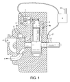
claim 1. The insertion of a valve into the fluid connection between the commutating means and each of the working chambers allows each working chamber to be isolated from the commutating means. Chambers which are isolated in this way by the valve operate in an idle condition, whereby no useful fluid work is done by the chamber, and thus the displacement per revolution of the machine is reduced. In its simplest embodiment such valves may be controlled mechanically, allowing the machine to be used in a reduced displacement mode when it is desired, for instance, to operate at high speed. Such mechanical control may be automatic, for instance reducing the displacement of the machine as the speed of rotation increases above a threshold. The valves are individually controlled by an electronic signal, allowing each of the chambers to be isolated according to the command of an electronic controller. Preferably such controller has an input signal of the position of the shaft of the machine, allowing the timing of the valve actuation to be phased relative to the position of the shaft, allowing each chamber to be isolated from the commutator on a stroke-by-stroke basis. Preferred or optional features of the machine are set forth in the dependent claims. - A particular embodiment of the invention is described below in more detail, by way of example only, and with reference to the accompanying drawing, the single figure of which is a schematic section of a machine according to the invention.
- The drawing shows a machine comprising a
working chamber 4 in the form of cylinder containing a piston actuating acrankshaft 5. Aconventional commutator plate 2 alternately connects thechamber 4 to port A or, via atoroidal cavity 10, to port B, one of the ports being a high-pressure port and the other a low-pressure port. As shown, the machine operates as a motor with fluid being supplied at high pressure at port A and exhausted at low pressure at port B, but both the pressures and the direction of flow could be reversed separately without changing the apparatus shown. - By placing an actively controllable on-off
valve 1, in series with a rotatingcommutator plate 2, into thefluid passage 3 between the commutator plate and theworking chamber 4, the flow into the working chamber can be controlled. When the machine is working with theshaft 5 rotating, and the on-off valve closed prior to the opening of thefluid inlet port 2a on the commutator, then the expansion stroke of the working chamber will occur in a partial vacuum. If the fluid is a liquid such as oil, a bubble is formed as air is drawn out of the liquid. The return stroke will collapse the bubble by the time the chamber returns to its minimum volume. In doing so the working volume will have exchanged no work with the fluid system while absorbing very little parasitic work. It is alternatively possible to avoid cavitation and air-release by fitting a fluid connection including anon-return valve 4a between the working chamber and the low-pressure line, possibly via the crank case as shown. Operating the working chamber with the on-off valve closed will result in an idle cycle. - When the
valve 1 is left in the open position the working chamber functions, as normal, to produce a working cycle. The time averaged flow is varied by deciding on a chamber-by-chamber basis whether to effect idle or working cycles. The decisions are taken as each successive chamber nears the minimum volume condition, irrespective of whether the machine is working as a pump or a motor. Anelectronic controller 6 senses the phase of the working chamber cycle using a once-per-revolution shaft sensor 7, an encoder, a resolver or some similar means. At times coinciding with the minimum working chamber volume the controller can either leave the on-off valve in its de-energised open state or pull it closed through electromagnetic means. In addition to the timing function, the controller reads the system demand, either through an analogue or digital input line or a bus 8, and decides whether the working chamber reaching the minimum volume condition should be left working or idled by closing thevalve 1. In the embodiment shown, the on-offvalve 1 defaults to the open position and is pulsed to close, but it is possible to see that the opposite operating mode, i.e. default closed, pulse to open would also have application where a power-off freewheel characteristic was required. - The controller decisions can also be made entirely on the basis of shaft speed in order to limit the rate of increase of shaft power. In such a mode of operation the electronic controller would require no external demand signal and would make the sequential on-off valve actuation decisions on the basis of a pre-programmed flow versus speed function.
- In the instance of a vehicle propulsion circuit, where external demand signals are read by the electronic controller, the decision sequence can be determined in order to limit individual wheel slip, to create a skid steering effect or to create graded changes in torque and thus controlled vehicle accelerations.
Claims (9)
- A fluid-working machine with variable volume working chambers (4), each of which is connected to a fluid commutating means (2) which alternately connects the working chamber to either of two fluid manifolds (A, B), wherein an electronically controlled valve member (1) is inserted into the flow path (3) between each chamber (4) and the commutating means.
- A fluid-working machine as clamed in claim 1, wherein a controller (6) for controlling the valve member (1) receives an input signal of the phase angle of a shaft (5) of the machine or at least one electronic pulse per revolution which informs the controller (6) that the shaft is passing a known phase angle.
- A fluid-working machine as claimed in claim 2, wherein the controller (6) is arranged to choose whether to actuate the valve member (1), each time the working chamber volume is approaching its minimum, such that the valve is closed at a time close to the time the working chamber (4) begins its expansion stroke, if it is desired to isolate the working chamber from the commutating means (2).
- A fluid-working machine as claimed in claim 3, wherein the controller (6) sums the previous flow demand to create a total displacement demand and compares it with the actual displacement through the machine over the same time period to determine the displacement error and the controller chooses either to isolate the working chamber (4) or to leave it active in order to minimise the ongoing accumulated displacement error.
- A fluid-working machine as claimed in claim 3, wherein the controller (6) reads a demand from an external signal line and decides whether to isolate working chambers (4), as they reach the minimum volume condition, in order to regulate one of speed, torque, volumetric flow rate, power and volume displaced per revolution.
- A fluid-working machine as claimed in claim 3, wherein the controller makes decisions to isolate working chambers (4) on the basis of sensed shaft speed so that the ratio of working cylinders (4) to idle cylinders (4) decreases, according to a predetermined function, as the machine speeds up, in order to either maintain a constant level of throughput flow or one which rises less quickly than the shaft speed increase would indicate.
- A fluid-working machine as claimed in claim 2, wherein the machine is arranged to work as a motor, and the controller (6) can choose to close the valve member (1) some fraction of the way into an expansion stroke of the chamber (4), such that the chamber is connected to the commutating means (2) for only a fraction of the expansion stroke, such that the volume of fluid working to drive the load in that expansion stroke is a fraction of the full geometric displacement of the chamber (4).
- A fluid-working machine as claimed in claim 2, wherein the machine is arranged to work as a pump, and the controller (6) can choose to close the valve member (1) some fraction of the way into the expansion stroke of the chamber (4), such that the chamber is connected to the commutating means (2) for only a fraction of a full working stroke, such that part of an expansion stroke consists of pulling a partial vacuum in the chamber (4), such that when a next contraction stroke begins, the chamber does not act as a pump immediately but at some fraction of the way into the contraction stroke, such that the contraction stroke displaces only a fraction of the full geometric displacement of the chamber (4) into the commutating means (2).
- A fluid-working machine as claimed in claim 2, wherein the controller (6) is operable to reduce the loss of energy in the compressed fluid by closing the valve member (1) just before the chamber reaches its maximum volume condition so that the remaining expansion can de-pressurise the fluid contained within the chamber (4) before the commutating valve port is opened to the low-pressure manifold.
Applications Claiming Priority (2)
| Application Number | Priority Date | Filing Date | Title |
|---|---|---|---|
| GBGB0407297.1A GB0407297D0 (en) | 2004-03-31 | 2004-03-31 | Fluid working machine with displacement control |
| PCT/GB2005/001235 WO2005095800A1 (en) | 2004-03-31 | 2005-03-31 | Fluid-working machine with displacement control |
Publications (2)
| Publication Number | Publication Date |
|---|---|
| EP1738077A1 EP1738077A1 (en) | 2007-01-03 |
| EP1738077B1 true EP1738077B1 (en) | 2010-05-05 |
Family
ID=32247599
Family Applications (1)
| Application Number | Title | Priority Date | Filing Date |
|---|---|---|---|
| EP05729670A Not-in-force EP1738077B1 (en) | 2004-03-31 | 2005-03-31 | Fluid-working machine with displacement control |
Country Status (8)
| Country | Link |
|---|---|
| US (1) | US20070258832A1 (en) |
| EP (1) | EP1738077B1 (en) |
| JP (1) | JP2007530865A (en) |
| CN (1) | CN100587269C (en) |
| AT (1) | ATE467049T1 (en) |
| DE (1) | DE602005021087D1 (en) |
| GB (1) | GB0407297D0 (en) |
| WO (1) | WO2005095800A1 (en) |
Families Citing this family (21)
| Publication number | Priority date | Publication date | Assignee | Title |
|---|---|---|---|---|
| US7380490B2 (en) | 2004-02-11 | 2008-06-03 | Haldex Hydraulics Corporation | Housing for rotary hydraulic machines |
| US7402027B2 (en) | 2004-02-11 | 2008-07-22 | Haldex Hydraulics Corporation | Rotating group of a hydraulic machine |
| US7086225B2 (en) | 2004-02-11 | 2006-08-08 | Haldex Hydraulics Corporation | Control valve supply for rotary hydraulic machine |
| US7364409B2 (en) | 2004-02-11 | 2008-04-29 | Haldex Hydraulics Corporation | Piston assembly for rotary hydraulic machines |
| US7841432B2 (en) | 2004-11-22 | 2010-11-30 | Bosch Rexroth Corporation | Hydro-electric hybrid drive system for motor vehicle |
| US7516613B2 (en) | 2004-12-01 | 2009-04-14 | Haldex Hydraulics Corporation | Hydraulic drive system |
| DE102007016517A1 (en) | 2007-04-05 | 2008-10-09 | Muller, Katherina | Hydrostatic transmission for e.g. tractor, has mechanical torque/rotary speed converter i.e. planetary gear, connected with output shaft, where mechanical torque change is simultaneously balanced by inverse torque change on shaft |
| DE112008002963A5 (en) * | 2007-11-09 | 2010-09-02 | Muller, Katherina | Hydraulic pressure transformer and method of operation |
| GB0811385D0 (en) * | 2008-06-20 | 2008-07-30 | Artemis Intelligent Power Ltd | Fluid working machines and method |
| WO2010115018A1 (en) | 2009-04-02 | 2010-10-07 | Husco International, Inc. | Fluid working machine with selectively reversible check valve assemblies and method of operation |
| NO2239463T3 (en) * | 2009-04-07 | 2018-03-10 | ||
| EP2322802B1 (en) * | 2009-11-13 | 2014-01-08 | Artemis Intelligent Power Limited | Electronically controlled valve |
| CN103038507B (en) * | 2010-02-23 | 2016-04-06 | 阿尔特弥斯智能动力有限公司 | The valve timing of fluid-working machine |
| KR101355261B1 (en) | 2010-02-23 | 2014-01-27 | 아르테미스 인텔리전트 파워 리미티드 | Fluid-working machine and method of operating a fluid-working machine |
| GB2477997B (en) | 2010-02-23 | 2015-01-14 | Artemis Intelligent Power Ltd | Fluid working machine and method for operating fluid working machine |
| US8534687B2 (en) | 2010-07-05 | 2013-09-17 | Fluid Ride Ltd. | Suspension strut for a vehicle |
| GB201012743D0 (en) * | 2010-07-29 | 2010-09-15 | Isentropic Ltd | Valves |
| DE102010046217A1 (en) * | 2010-09-21 | 2012-03-22 | Robert Bosch Gmbh | Pressure control with DDU / DVR units using engine cycles |
| US8936135B2 (en) * | 2010-11-29 | 2015-01-20 | Lincoln Industrial Corporation | Pump having heated reservoir |
| US9574582B2 (en) | 2012-04-23 | 2017-02-21 | Fluid Ride, Ltd. | Hydraulic pump system and method of operation |
| EP2851585B1 (en) * | 2013-09-18 | 2016-04-13 | Artemis Intelligent Power Limited | Hydraulic transmission and method of controlling hydraulic transmission |
Family Cites Families (14)
| Publication number | Priority date | Publication date | Assignee | Title |
|---|---|---|---|---|
| US1774662A (en) * | 1928-04-12 | 1930-09-02 | Arthur S Parks | Vacuum pump |
| BE758118A (en) * | 1969-11-07 | 1971-04-01 | Riva Calzoni Spa | DISTRIBUTOR FOR HYDRAULIC MOTORS WITH RADIANT PISTONS AND OTHER SIMILAR MOTORS |
| JPS6341586Y2 (en) * | 1978-09-29 | 1988-11-01 | ||
| JPS55137374A (en) * | 1979-04-13 | 1980-10-27 | Kawasaki Heavy Ind Ltd | Radial piston motor with valve plate type distributor |
| GB8822901D0 (en) * | 1988-09-29 | 1988-11-02 | Mactaggart Scot Holdings Ltd | Apparatus & method for controlling actuation of multi-piston pump &c |
| JP2684804B2 (en) * | 1990-01-19 | 1997-12-03 | 日産自動車株式会社 | Control device for positive displacement pump |
| JP2979904B2 (en) * | 1993-06-29 | 1999-11-22 | 日産自動車株式会社 | Flow control device for positive displacement hydraulic pump |
| US5456581A (en) * | 1994-08-12 | 1995-10-10 | The United States Of America As Represented By The Secretary Of The Navy | Control system for a multi-piston pump with solenoid valves for the production of constant outlet pressure flow |
| US5564905A (en) * | 1994-10-18 | 1996-10-15 | Caterpillar Inc. | Displacement control for a variable displacement axial piston pump |
| JPH08303325A (en) * | 1995-05-01 | 1996-11-19 | Aisan Ind Co Ltd | Control method of flow control valve for high pressure fuel pump |
| DE69919658T2 (en) * | 1998-05-26 | 2005-09-15 | Caterpillar Inc., Peoria | HYDRAULIC SYSTEM WITH A PUMP WITH A VARIABLE DELIVERY VOLUME |
| JP3374770B2 (en) * | 1998-11-18 | 2003-02-10 | トヨタ自動車株式会社 | Control device for variable discharge rate pump |
| US6176684B1 (en) * | 1998-11-30 | 2001-01-23 | Caterpillar Inc. | Variable displacement hydraulic piston unit with electrically operated variable displacement control and timing control |
| US6681571B2 (en) * | 2001-12-13 | 2004-01-27 | Caterpillar Inc | Digital controlled fluid translating device |
-
2004
- 2004-03-31 GB GBGB0407297.1A patent/GB0407297D0/en not_active Ceased
-
2005
- 2005-03-31 JP JP2007505631A patent/JP2007530865A/en active Pending
- 2005-03-31 AT AT05729670T patent/ATE467049T1/en not_active IP Right Cessation
- 2005-03-31 DE DE602005021087T patent/DE602005021087D1/de active Active
- 2005-03-31 WO PCT/GB2005/001235 patent/WO2005095800A1/en active Application Filing
- 2005-03-31 US US10/599,475 patent/US20070258832A1/en not_active Abandoned
- 2005-03-31 CN CN200580014182A patent/CN100587269C/en not_active Expired - Fee Related
- 2005-03-31 EP EP05729670A patent/EP1738077B1/en not_active Not-in-force
Also Published As
| Publication number | Publication date |
|---|---|
| EP1738077A1 (en) | 2007-01-03 |
| WO2005095800A1 (en) | 2005-10-13 |
| US20070258832A1 (en) | 2007-11-08 |
| DE602005021087D1 (en) | 2010-06-17 |
| CN1973133A (en) | 2007-05-30 |
| CN100587269C (en) | 2010-02-03 |
| ATE467049T1 (en) | 2010-05-15 |
| JP2007530865A (en) | 2007-11-01 |
| GB0407297D0 (en) | 2004-05-05 |
Similar Documents
| Publication | Publication Date | Title |
|---|---|---|
| EP1738077B1 (en) | Fluid-working machine with displacement control | |
| EP0494236B1 (en) | Improved fluid-working machine | |
| US5259738A (en) | Fluid-working machine | |
| EP2307721B1 (en) | Fluid working machines and methods | |
| EP1537333B1 (en) | Fluid-working machine and operating method | |
| EP2049778B1 (en) | A cooling system and a transmission system having said cooling system integrated therewith | |
| JP2007530865A5 (en) | ||
| US8869521B2 (en) | Fluid working machine with cylinders coupled to split exterior ports by electrohydraulic valves | |
| FI121090B (en) | Apparatus, control circuit and method for generating pressure and volume flow | |
| US5813841A (en) | Hydraulic pressure control system for a pump | |
| GB2459520A (en) | Fluid machine with secondary low pressure port opening before controlled primary valve | |
| CN110892135B (en) | Method and device for gas expansion using a reciprocating piston machine | |
| US8469677B1 (en) | Check valve pump with electric bypass valve |
Legal Events
| Date | Code | Title | Description |
|---|---|---|---|
| PUAI | Public reference made under article 153(3) epc to a published international application that has entered the european phase |
Free format text: ORIGINAL CODE: 0009012 |
|
| 17P | Request for examination filed |
Effective date: 20061004 |
|
| AK | Designated contracting states |
Kind code of ref document: A1 Designated state(s): AT BE BG CH CY CZ DE DK EE ES FI FR GB GR HU IE IS IT LI LT LU MC NL PL PT RO SE SI SK TR |
|
| DAX | Request for extension of the european patent (deleted) | ||
| 17Q | First examination report despatched |
Effective date: 20071127 |
|
| GRAP | Despatch of communication of intention to grant a patent |
Free format text: ORIGINAL CODE: EPIDOSNIGR1 |
|
| GRAS | Grant fee paid |
Free format text: ORIGINAL CODE: EPIDOSNIGR3 |
|
| RAP1 | Party data changed (applicant data changed or rights of an application transferred) |
Owner name: ARTEMIS INTELLIGENT POWER LIMITED |
|
| GRAA | (expected) grant |
Free format text: ORIGINAL CODE: 0009210 |
|
| AK | Designated contracting states |
Kind code of ref document: B1 Designated state(s): AT BE BG CH CY CZ DE DK EE ES FI FR GB GR HU IE IS IT LI LT LU MC NL PL PT RO SE SI SK TR |
|
| REG | Reference to a national code |
Ref country code: GB Ref legal event code: FG4D |
|
| REG | Reference to a national code |
Ref country code: CH Ref legal event code: EP |
|
| REG | Reference to a national code |
Ref country code: IE Ref legal event code: FG4D |
|
| REF | Corresponds to: |
Ref document number: 602005021087 Country of ref document: DE Date of ref document: 20100617 Kind code of ref document: P |
|
| REG | Reference to a national code |
Ref country code: NL Ref legal event code: VDEP Effective date: 20100505 |
|
| LTIE | Lt: invalidation of european patent or patent extension |
Effective date: 20100505 |
|
| PG25 | Lapsed in a contracting state [announced via postgrant information from national office to epo] |
Ref country code: SE Free format text: LAPSE BECAUSE OF FAILURE TO SUBMIT A TRANSLATION OF THE DESCRIPTION OR TO PAY THE FEE WITHIN THE PRESCRIBED TIME-LIMIT Effective date: 20100505 Ref country code: ES Free format text: LAPSE BECAUSE OF FAILURE TO SUBMIT A TRANSLATION OF THE DESCRIPTION OR TO PAY THE FEE WITHIN THE PRESCRIBED TIME-LIMIT Effective date: 20100816 Ref country code: LT Free format text: LAPSE BECAUSE OF FAILURE TO SUBMIT A TRANSLATION OF THE DESCRIPTION OR TO PAY THE FEE WITHIN THE PRESCRIBED TIME-LIMIT Effective date: 20100505 Ref country code: NL Free format text: LAPSE BECAUSE OF FAILURE TO SUBMIT A TRANSLATION OF THE DESCRIPTION OR TO PAY THE FEE WITHIN THE PRESCRIBED TIME-LIMIT Effective date: 20100505 |
|
| PG25 | Lapsed in a contracting state [announced via postgrant information from national office to epo] |
Ref country code: AT Free format text: LAPSE BECAUSE OF FAILURE TO SUBMIT A TRANSLATION OF THE DESCRIPTION OR TO PAY THE FEE WITHIN THE PRESCRIBED TIME-LIMIT Effective date: 20100505 Ref country code: FI Free format text: LAPSE BECAUSE OF FAILURE TO SUBMIT A TRANSLATION OF THE DESCRIPTION OR TO PAY THE FEE WITHIN THE PRESCRIBED TIME-LIMIT Effective date: 20100505 Ref country code: SI Free format text: LAPSE BECAUSE OF FAILURE TO SUBMIT A TRANSLATION OF THE DESCRIPTION OR TO PAY THE FEE WITHIN THE PRESCRIBED TIME-LIMIT Effective date: 20100505 Ref country code: IS Free format text: LAPSE BECAUSE OF FAILURE TO SUBMIT A TRANSLATION OF THE DESCRIPTION OR TO PAY THE FEE WITHIN THE PRESCRIBED TIME-LIMIT Effective date: 20100905 |
|
| PG25 | Lapsed in a contracting state [announced via postgrant information from national office to epo] |
Ref country code: GR Free format text: LAPSE BECAUSE OF FAILURE TO SUBMIT A TRANSLATION OF THE DESCRIPTION OR TO PAY THE FEE WITHIN THE PRESCRIBED TIME-LIMIT Effective date: 20100806 Ref country code: CY Free format text: LAPSE BECAUSE OF FAILURE TO SUBMIT A TRANSLATION OF THE DESCRIPTION OR TO PAY THE FEE WITHIN THE PRESCRIBED TIME-LIMIT Effective date: 20100505 Ref country code: PL Free format text: LAPSE BECAUSE OF FAILURE TO SUBMIT A TRANSLATION OF THE DESCRIPTION OR TO PAY THE FEE WITHIN THE PRESCRIBED TIME-LIMIT Effective date: 20100505 |
|
| PG25 | Lapsed in a contracting state [announced via postgrant information from national office to epo] |
Ref country code: DK Free format text: LAPSE BECAUSE OF FAILURE TO SUBMIT A TRANSLATION OF THE DESCRIPTION OR TO PAY THE FEE WITHIN THE PRESCRIBED TIME-LIMIT Effective date: 20100505 Ref country code: EE Free format text: LAPSE BECAUSE OF FAILURE TO SUBMIT A TRANSLATION OF THE DESCRIPTION OR TO PAY THE FEE WITHIN THE PRESCRIBED TIME-LIMIT Effective date: 20100505 Ref country code: PT Free format text: LAPSE BECAUSE OF FAILURE TO SUBMIT A TRANSLATION OF THE DESCRIPTION OR TO PAY THE FEE WITHIN THE PRESCRIBED TIME-LIMIT Effective date: 20100906 |
|
| PG25 | Lapsed in a contracting state [announced via postgrant information from national office to epo] |
Ref country code: CZ Free format text: LAPSE BECAUSE OF FAILURE TO SUBMIT A TRANSLATION OF THE DESCRIPTION OR TO PAY THE FEE WITHIN THE PRESCRIBED TIME-LIMIT Effective date: 20100505 Ref country code: SK Free format text: LAPSE BECAUSE OF FAILURE TO SUBMIT A TRANSLATION OF THE DESCRIPTION OR TO PAY THE FEE WITHIN THE PRESCRIBED TIME-LIMIT Effective date: 20100505 Ref country code: RO Free format text: LAPSE BECAUSE OF FAILURE TO SUBMIT A TRANSLATION OF THE DESCRIPTION OR TO PAY THE FEE WITHIN THE PRESCRIBED TIME-LIMIT Effective date: 20100505 Ref country code: BE Free format text: LAPSE BECAUSE OF FAILURE TO SUBMIT A TRANSLATION OF THE DESCRIPTION OR TO PAY THE FEE WITHIN THE PRESCRIBED TIME-LIMIT Effective date: 20100505 |
|
| PLBE | No opposition filed within time limit |
Free format text: ORIGINAL CODE: 0009261 |
|
| STAA | Information on the status of an ep patent application or granted ep patent |
Free format text: STATUS: NO OPPOSITION FILED WITHIN TIME LIMIT |
|
| PG25 | Lapsed in a contracting state [announced via postgrant information from national office to epo] |
Ref country code: IT Free format text: LAPSE BECAUSE OF FAILURE TO SUBMIT A TRANSLATION OF THE DESCRIPTION OR TO PAY THE FEE WITHIN THE PRESCRIBED TIME-LIMIT Effective date: 20100505 |
|
| 26N | No opposition filed |
Effective date: 20110208 |
|
| REG | Reference to a national code |
Ref country code: DE Ref legal event code: R097 Ref document number: 602005021087 Country of ref document: DE Effective date: 20110207 |
|
| PG25 | Lapsed in a contracting state [announced via postgrant information from national office to epo] |
Ref country code: MC Free format text: LAPSE BECAUSE OF NON-PAYMENT OF DUE FEES Effective date: 20110331 |
|
| REG | Reference to a national code |
Ref country code: CH Ref legal event code: PL |
|
| REG | Reference to a national code |
Ref country code: IE Ref legal event code: MM4A |
|
| PG25 | Lapsed in a contracting state [announced via postgrant information from national office to epo] |
Ref country code: LI Free format text: LAPSE BECAUSE OF NON-PAYMENT OF DUE FEES Effective date: 20110331 Ref country code: IE Free format text: LAPSE BECAUSE OF NON-PAYMENT OF DUE FEES Effective date: 20110331 Ref country code: CH Free format text: LAPSE BECAUSE OF NON-PAYMENT OF DUE FEES Effective date: 20110331 |
|
| PG25 | Lapsed in a contracting state [announced via postgrant information from national office to epo] |
Ref country code: LU Free format text: LAPSE BECAUSE OF NON-PAYMENT OF DUE FEES Effective date: 20110331 |
|
| PG25 | Lapsed in a contracting state [announced via postgrant information from national office to epo] |
Ref country code: TR Free format text: LAPSE BECAUSE OF FAILURE TO SUBMIT A TRANSLATION OF THE DESCRIPTION OR TO PAY THE FEE WITHIN THE PRESCRIBED TIME-LIMIT Effective date: 20100505 Ref country code: BG Free format text: LAPSE BECAUSE OF FAILURE TO SUBMIT A TRANSLATION OF THE DESCRIPTION OR TO PAY THE FEE WITHIN THE PRESCRIBED TIME-LIMIT Effective date: 20100805 |
|
| PG25 | Lapsed in a contracting state [announced via postgrant information from national office to epo] |
Ref country code: HU Free format text: LAPSE BECAUSE OF FAILURE TO SUBMIT A TRANSLATION OF THE DESCRIPTION OR TO PAY THE FEE WITHIN THE PRESCRIBED TIME-LIMIT Effective date: 20100505 |
|
| PGFP | Annual fee paid to national office [announced via postgrant information from national office to epo] |
Ref country code: DE Payment date: 20140328 Year of fee payment: 10 |
|
| REG | Reference to a national code |
Ref country code: DE Ref legal event code: R119 Ref document number: 602005021087 Country of ref document: DE |
|
| PG25 | Lapsed in a contracting state [announced via postgrant information from national office to epo] |
Ref country code: DE Free format text: LAPSE BECAUSE OF NON-PAYMENT OF DUE FEES Effective date: 20151001 |
|
| REG | Reference to a national code |
Ref country code: FR Ref legal event code: PLFP Year of fee payment: 12 |
|
| REG | Reference to a national code |
Ref country code: FR Ref legal event code: PLFP Year of fee payment: 13 |
|
| REG | Reference to a national code |
Ref country code: FR Ref legal event code: PLFP Year of fee payment: 14 |
|
| PGFP | Annual fee paid to national office [announced via postgrant information from national office to epo] |
Ref country code: GB Payment date: 20220210 Year of fee payment: 18 |
|
| PGFP | Annual fee paid to national office [announced via postgrant information from national office to epo] |
Ref country code: FR Payment date: 20220221 Year of fee payment: 18 |
|
| GBPC | Gb: european patent ceased through non-payment of renewal fee |
Effective date: 20230331 |
|
| PG25 | Lapsed in a contracting state [announced via postgrant information from national office to epo] |
Ref country code: GB Free format text: LAPSE BECAUSE OF NON-PAYMENT OF DUE FEES Effective date: 20230331 |
|
| PG25 | Lapsed in a contracting state [announced via postgrant information from national office to epo] |
Ref country code: GB Free format text: LAPSE BECAUSE OF NON-PAYMENT OF DUE FEES Effective date: 20230331 Ref country code: FR Free format text: LAPSE BECAUSE OF NON-PAYMENT OF DUE FEES Effective date: 20230331 |