EP1737627B1 - Table saw guard - Google Patents
Table saw guard Download PDFInfo
- Publication number
- EP1737627B1 EP1737627B1 EP05740164A EP05740164A EP1737627B1 EP 1737627 B1 EP1737627 B1 EP 1737627B1 EP 05740164 A EP05740164 A EP 05740164A EP 05740164 A EP05740164 A EP 05740164A EP 1737627 B1 EP1737627 B1 EP 1737627B1
- Authority
- EP
- European Patent Office
- Prior art keywords
- support structure
- assembly
- guard assembly
- table saw
- release mechanism
- Prior art date
- Legal status (The legal status is an assumption and is not a legal conclusion. Google has not performed a legal analysis and makes no representation as to the accuracy of the status listed.)
- Expired - Lifetime
Links
Images






Classifications
-
- B—PERFORMING OPERATIONS; TRANSPORTING
- B27—WORKING OR PRESERVING WOOD OR SIMILAR MATERIAL; NAILING OR STAPLING MACHINES IN GENERAL
- B27G—ACCESSORY MACHINES OR APPARATUS FOR WORKING WOOD OR SIMILAR MATERIALS; TOOLS FOR WORKING WOOD OR SIMILAR MATERIALS; SAFETY DEVICES FOR WOOD WORKING MACHINES OR TOOLS
- B27G19/00—Safety guards or devices specially adapted for wood saws; Auxiliary devices facilitating proper operation of wood saws
- B27G19/02—Safety guards or devices specially adapted for wood saws; Auxiliary devices facilitating proper operation of wood saws for circular saws
- B27G19/025—Safety guards or devices specially adapted for wood saws; Auxiliary devices facilitating proper operation of wood saws for circular saws with guards for tool
-
- B—PERFORMING OPERATIONS; TRANSPORTING
- B27—WORKING OR PRESERVING WOOD OR SIMILAR MATERIAL; NAILING OR STAPLING MACHINES IN GENERAL
- B27G—ACCESSORY MACHINES OR APPARATUS FOR WORKING WOOD OR SIMILAR MATERIALS; TOOLS FOR WORKING WOOD OR SIMILAR MATERIALS; SAFETY DEVICES FOR WOOD WORKING MACHINES OR TOOLS
- B27G19/00—Safety guards or devices specially adapted for wood saws; Auxiliary devices facilitating proper operation of wood saws
- B27G19/08—Accessories for keeping open the saw kerf, e.g. riving knives or wedge plates
-
- Y—GENERAL TAGGING OF NEW TECHNOLOGICAL DEVELOPMENTS; GENERAL TAGGING OF CROSS-SECTIONAL TECHNOLOGIES SPANNING OVER SEVERAL SECTIONS OF THE IPC; TECHNICAL SUBJECTS COVERED BY FORMER USPC CROSS-REFERENCE ART COLLECTIONS [XRACs] AND DIGESTS
- Y10—TECHNICAL SUBJECTS COVERED BY FORMER USPC
- Y10T—TECHNICAL SUBJECTS COVERED BY FORMER US CLASSIFICATION
- Y10T83/00—Cutting
- Y10T83/202—With product handling means
- Y10T83/2074—Including means to divert one portion of product from another
- Y10T83/2077—By kerf entering guide
-
- Y—GENERAL TAGGING OF NEW TECHNOLOGICAL DEVELOPMENTS; GENERAL TAGGING OF CROSS-SECTIONAL TECHNOLOGIES SPANNING OVER SEVERAL SECTIONS OF THE IPC; TECHNICAL SUBJECTS COVERED BY FORMER USPC CROSS-REFERENCE ART COLLECTIONS [XRACs] AND DIGESTS
- Y10—TECHNICAL SUBJECTS COVERED BY FORMER USPC
- Y10T—TECHNICAL SUBJECTS COVERED BY FORMER US CLASSIFICATION
- Y10T83/00—Cutting
- Y10T83/768—Rotatable disc tool pair or tool and carrier
- Y10T83/7684—With means to support work relative to tool[s]
- Y10T83/773—Work-support includes passageway for tool [e.g., slotted table]
-
- Y—GENERAL TAGGING OF NEW TECHNOLOGICAL DEVELOPMENTS; GENERAL TAGGING OF CROSS-SECTIONAL TECHNOLOGIES SPANNING OVER SEVERAL SECTIONS OF THE IPC; TECHNICAL SUBJECTS COVERED BY FORMER USPC CROSS-REFERENCE ART COLLECTIONS [XRACs] AND DIGESTS
- Y10—TECHNICAL SUBJECTS COVERED BY FORMER USPC
- Y10T—TECHNICAL SUBJECTS COVERED BY FORMER US CLASSIFICATION
- Y10T83/00—Cutting
- Y10T83/869—Means to drive or to guide tool
- Y10T83/872—With guard means
- Y10T83/8722—Static
-
- Y—GENERAL TAGGING OF NEW TECHNOLOGICAL DEVELOPMENTS; GENERAL TAGGING OF CROSS-SECTIONAL TECHNOLOGIES SPANNING OVER SEVERAL SECTIONS OF THE IPC; TECHNICAL SUBJECTS COVERED BY FORMER USPC CROSS-REFERENCE ART COLLECTIONS [XRACs] AND DIGESTS
- Y10—TECHNICAL SUBJECTS COVERED BY FORMER USPC
- Y10T—TECHNICAL SUBJECTS COVERED BY FORMER US CLASSIFICATION
- Y10T83/00—Cutting
- Y10T83/869—Means to drive or to guide tool
- Y10T83/872—With guard means
- Y10T83/8722—Static
- Y10T83/8723—Adjustable
-
- Y—GENERAL TAGGING OF NEW TECHNOLOGICAL DEVELOPMENTS; GENERAL TAGGING OF CROSS-SECTIONAL TECHNOLOGIES SPANNING OVER SEVERAL SECTIONS OF THE IPC; TECHNICAL SUBJECTS COVERED BY FORMER USPC CROSS-REFERENCE ART COLLECTIONS [XRACs] AND DIGESTS
- Y10—TECHNICAL SUBJECTS COVERED BY FORMER USPC
- Y10T—TECHNICAL SUBJECTS COVERED BY FORMER US CLASSIFICATION
- Y10T83/00—Cutting
- Y10T83/95—Machine frame
- Y10T83/96—Guard
Definitions
- the present invention relates generally to table saw guard assemblies and specifically to modular table saw guard assemblies for preventing a user from accidentally engaging the table saw blade.
- Table saw guards have been designed to prevent an operator from accidentally engaging a table saw blade.
- the typical table saw guard includes a one piece hood pivotally connected to a support structure, whereby introducing a workpiece to the front of the hood causes it to rise. While these guards provide adequate protection, they tend to be cumbersome and often impede visibility to the saw blade. Furthermore, these guards can occasionally bind when cutting miter or bevel angles. Hence, to avoid these obstacles, operators often remove the hood assembly.
- US3105530 discloses a table saw guard assembly according to the preamble of claim 1 and of claim 11.
- a table saw guard assembly comprising the features of claim 1.
- a table saw guard assembly comprising the features of claim 11.
- One aspect of the present invention provides a table saw guard assembly having independently moveable side curtains. Another aspect of the present invention provides a table saw guard assembly having independently removable side curtains. Still another aspect of the present invention provides a table saw guard assembly having a support structure, which enables the table saw guard assembly to be easily removed from the working area. A still further aspect of the present invention provides a table saw guard assembly having a locking mechanism for securing the guard at a fixed position above the table saw. It is yet a further aspect of the present invention to provide a table saw guard assembly, which provides an unimpeded view of the workpiece and the table saw blade during operation.
- Figure 1 is a perspective view of a first embodiment of the table saw guard assembly of the present invention
- Figure 2 is a perspective view of the table saw guard assembly of Figure 1 , wherein one side curtain is fixed at a position different from the other side curtain;
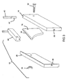
- Figure 3 is an exploded perspective view of the table saw guard assembly of Figure 1 ;
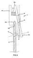
- Figure 4 is a cross sectional view of a first embodiment of a quick release mechanism for attaching a hood assembly to a support structure of the present invention
- Figure 5 is a perspective view of an alternative embodiment of the table saw guard assembly of Figure 1 ;
- Figure 6 is a perspective view of a second embodiment of the table saw guard assembly of the present invention.
- Figure 7 is a perspective view of the table saw guard assembly of Figure 6 , wherein one side assembly is removed therefrom;
- Figure 8 is an exploded perspective view of the table saw guard assembly of Figure 6 ;
- Figure 9 is a cross sectional detail view of a second embodiment of a quick release mechanism for attaching a hood assembly to a support structure of the table saw guard assembly of Figure 6 ;
- Figure 10 is a cross sectional detail view of an embodiment of a quick release mechanism for attaching the side assemblies to the top curtain of the table saw guard assembly of Figure 6 ;
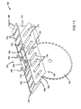
- Figure 11 is a perspective view of an alternative embodiment of the table saw guard assembly of Figure 6 ;
- Figure 12 is a perspective view of a third embodiment of the table saw guard assembly of the present invention.
- Figure 13 is an exploded perspective view of the table saw guard assembly of Figure 12 ;
- Figure 14 is a perspective view of an alternative embodiment of the table saw guard assembly of Figure 12 ;
- Figure 15 is a front elevational view of a fourth embodiment of the table saw guard assembly of the present invention.
- Figure 16 is a side elevational view of the table saw guard assembly of Figure 15 ;
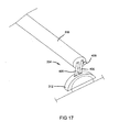
- Figure 17 is a perspective view of an alternative embodiment of a mounting assembly of a fourth embodiment of the present invention.
- the table saw guard assembly 12 generally includes a support structure and a hood assembly supported above a saw blade 14 by the support structure.
- the support structure generally includes a riving knife 10 having an aperture 16 therethrough located immediately behind the saw blade 14.
- the hood assembly includes a first side curtain 18, a second side curtain 20, a mounting member 22, a first locking mechanism 24, and a second locking mechanism 26.
- the first and second side curtains 18, 20 include transparent bodies.
- the first and second side curtains 18', 20' include bodies having a plurality of apertures 74 therethrough (as shown in Figure 5 ).
- the first side curtain 18 includes a first coupler 28 and the second side curtain 20 includes a second coupler 30.
- the first coupler 28 includes a female snap-fit connector and the second coupler 30 includes a male snap-fit connector adapted to selectively interconnect with the first coupler 28. Engaging the first and second couplers 28, 30 provides for codependent movement of the first and second side curtains 18, 20.
- the first locking mechanism 24 is provided for pivotally connecting the first and second side curtains 18, 20 to the mounting member 22.
- the first locking mechanism 24 includes a screw 32 and a wing nut 34 threadably engaging the screw 32, and is further adapted to enable selective removal of the first and second side curtains 18, 20.
- the mounting member 22 includes a solid member having an aperture 36 disposed horizontally therethrough for receiving the screw 32 of the first locking mechanism 24.
- the second locking mechanism 26 is attached toward a backside of the mounting member 22 and includes a quick release mechanism.
- the quick release mechanism includes a block 38 and a lever 40 operably attached to a pivot pin 42.
- the block 38 includes a v-shaped recess 38a formed in an underside thereof for engaging a v-shaped edge 10a on the riving knife 10.
- the lever 40 is operable between an open position and a closed position (shown in phantom in Figure 4 ).
- the lever 40 includes a top end 40a and a bottom end 40b having a lock pin 44 extending from an inner side thereof for selectively engaging the aperture 16 in the riving knife 10.
- the lock pin 44 extends from the lever 40 at a slight angle upward relative an axis A, such that when the lock pin 44 enters the aperture 16, it engages a top surface of the aperture 16 and biases the hood assembly onto the riving knife 10.
- the mechanism further includes a coil spring 46 disposed between the block 38 and the upper end 40a of the lever 40 for biasing the lever 40 in the closed position.
- the second quick release mechanism includes a spring biased lock member adapted to engage the riving knife 10 as described below in reference to Figure 9 .
- the wing nut 34 of the first locking mechanism 24 is loosened to allow one (as shown in Figure 2 ) or both (as shown in Figure 1 ) of the first and second side curtains 18, 20 to be pivotally adjusted. Thereafter, the wing nut 34 is tightened to secure the first and second side curtains 18, 20 in a predetermined position. Furthermore, the wing nut 34 may be removed from the screw 32 and the screw removed from the aperture 36 in the mounting member 22 to allow one or both of the side curtains 18, 20 to be removed therefrom. Lastly, the entire hood assembly 12 is removed from the support structure by disengaging the second locking mechanism 26.
- Disengagement is accomplished by squeezing the top end 40a of the push tab 40 thereby pivoting the push tab 40 about the pivot pin 42 toward the open position and extracting the lock pin 44 from the aperture 16 in the riving knife 10. Thereafter, the hood assembly is raised off of the riving knife 10.
- a second embodiment of a table saw guard assembly 100 including a support structure and a hood assembly supported above a saw blade 114 by the support structure.
- the support structure generally includes a riving knife 110 having a shoulder 150 (best shown in Figure 9 ) formed thereon located immediately behind the saw blade 114.
- the hood assembly includes a top curtain 102, a first side assembly 118, a second side assembly 120, a first locking mechanism 124, and a second locking mechanism 126.
- the top curtain 102 includes a transparent body and is disposed above the saw blade 114.
- the first side assembly 118 includes a first side curtain 154 having a transparent body and a first chamfered front edge 156, a first engagement plate 158, and first and second link arms 160, 162 connecting the first side curtain 154 to the first engagement plate 158.
- the second side assembly 120 includes a second side curtain 164 having a transparent body and a second chamfered front edge 166, a second engagement plate 168, and third and fourth link arms 170, 172 connecting the second side curtain 164 to the second engagement plate 168.
- the top curtain 102 and first and second side curtains 154, 164 each include a plurality of apertures 174 therethrough for providing a sight line to the saw blade 114 (as shown in Figure 11 ).
- the first locking assembly 124 includes a first quick release mechanism for independently and selectively attaching the first and second engagement plates 158, 168 of the first and second side assemblies 118, 120, respectively, to the top curtain 102.
- the first quick release mechanism includes a pull pin 176 biased downward by a coil spring 178, a first hook arm 180 and a second hook arm 182.
- the first and second hook arms 180, 182 are adapted to engage recesses 183 provided in the first and second engagement plates 158, 168, respectively, thereby securing the side assemblies 118, 120 to the top curtain 102.
- the first locking assembly 124 includes an upper housing member 185 mounted to the top curtain 102 for supporting the pull pin 176 and first and second hook arms 180, 182.
- a presently preferred embodiment of the second locking mechanism 126 includes a second quick release mechanism disposed at a rear side of the top curtain 102.
- the second quick release mechanism includes a lock member 48 adapted to engage the shoulder 150 on the riving knife 110 and a spring biased hinge 52 for biasing the lock member 48 against the shoulder 150 of the riving knife 110.
- the second quick release mechanism includes a block 38 and a lever 40 operably attached to a pivot pin 42, as described above with reference to Figure 4 .
- the block 38 includes a v-shaped recess 38a formed in an underside thereof for engaging a v-shaped edge 10a on the riving knife 110.
- the lever 40 is operable between an open position and a closed position (shown in phantom in Figure 4 ).
- the lever 40 includes a top end 40a and a bottom end 40b having a lock pin 44 extending from an inner side thereof for selectively engaging the aperture 16 in the riving knife 110.
- the lock pin 44 extends from the lever 40 at a slight angle upward relative an axis A, such that when the lock pin 44 enters an aperture 16, it engages a top surface of the aperture 16 and biases the hood assembly 100 onto the riving knife 110.
- the mechanism further includes a coil spring 46 disposed between the block 38 and the upper end 40a of the lever 40 for biasing the lever 40 in the closed position.
- a workpiece enters the hood assembly applying a force to the first and second chamfered front edges 156, 166 of the first and second side curtains 154, 164, thereby causing the first and second side curtains 154, 164 to independently pivot on the respective link members 160, 162 and 170, 172 relative to the top curtain 102.
- the pull pin 176 of the first quick release mechanism is raised, thereby disengaging the first and second hook arms 180, 182 from the first and second engagement plates 158, 168.
- This enables one or both of the first and second side assemblies 118, 120 to be independently removed from the top curtain 102.
- the pull pin 176 is released and the coil spring 178 biases the first and second hook arms 180, 182 back down to engage the remaining engagement plate(s) 158, 168.
- a coil spring is disclosed to bias the pull pin downward, other biasing means, such as a camlock, useful to achieve a similar result are intended to be within the scope of the present invention.
- the lock member 48 of the second quick release mechanism as shown in Figure 9 is pivoted, thereby disengaging the riving knife 50 and enabling the entire hood assembly 100 to be removed therefrom.
- a third embodiment of a table saw guard assembly 200 in accordance with the present invention including a support structure and a hood assembly supported above a saw blade 214 by the support structure.
- the support structure generally includes a riving knife 210 having an aperture 216 therethrough located immediately behind the saw blade 214.
- the hood assembly 200 includes a top curtain 202, a front curtain 254, a first locking mechanism 224, and a second locking mechanism 226.
- the top curtain 202 includes a transparent body disposed above the saw blade 214; and the front curtain 254 includes a transparent body disposed at a slight incline in front of the saw blade 214 and through a slot 255 in the top curtain 202.
- the top and front curtains 202', 254' each include a plurality of apertures 274 therethrough for providing a sight line to the saw blade 214.
- the first locking mechanism 224 slidably attaches the front curtain 254 to the top curtain 202.
- the first locking mechanism 224 includes a thumb screw 276 for being received in a threaded aperture 278 in the top curtain 202 and engaging the front curtain 254.
- the second locking mechanism 226 includes a quick release mechanism for selectively engaging the riving knife 210.
- the quick release mechanism 226 includes a block 38 and a lever 40 operably attached to a pivot pin 42.
- the block 38 includes a v-shaped recess 38a formed in an underside thereof for engaging a v-shaped edge 10a on the riving knife 210.
- the lever 40 is operable between an open position and a closed position (shown in phantom in Figure 4 ).
- the lever 40 includes a top end 40a and a bottom end 40b having a lock pin 44 extending from an inner side thereof for selectively engaging the aperture 216 in the riving knife 210.
- the lock pin 44 extends from the lever 40 at a slight angle upward relative an axis A, such that when the lock pin 44 enters the aperture 216, it engages a top surface of the aperture 216 and biases the hood assembly onto the riving knife 210.
- the mechanism further includes a coil spring 46 disposed between the block 38 and the upper end 40a of the lever 40 for biasing the lever 40 in the closed position.
- the second quick release mechanism includes a lock member 48 adapted to engage a shoulder 50 of the riving knife 210 and a spring biased hinge 52 for biasing the lock member against the shoulder 50 on the riving knife 210 (as shown in Figure 9 ).
- the thumb screw 276 is loosened, thereby enabling the front curtain 254 to slide relative to the top curtain 202 so that the front curtain 254 can be adjusted to a height of a work piece. Thereafter, the thumbscrew 276 is tightened to engage the front curtain 254 and secure it in a predetermined position.
- the entire hood assembly 200 is removed from the support structure by disengaging the quick release mechanism 226. Disengagement is accomplished by squeezing the top end of the lever 40 toward the block 38, thereby pivoting the lever 40 about the pivot pin 42 toward the open position and extracting the lock pin 44 from the aperture 216 in the riving knife 210. Thereafter, the hood assembly 200 is raised off of the riving knife 210.
- the table saw guard assembly 302 generally includes a support structure and a hood assembly 312 supported above the saw blade 314 by the support structure.
- the support structure includes a telescoping boom 316 and a base structure.
- the telescoping boom 316 includes three interconnecting sleeve members 316a, 316b, 316c and a pair of set screws 318 for adjusting the length and/or rotational orientation of the telescoping boom 316.
- the base structure includes a telescoping vertical arm assembly 320 and a telescoping horizontal arm assembly 322.
- the vertical arm assembly 320 includes two interconnected sleeve members 320a, 320b and a set screw 324 for adjusting the length and/or rotational orientation of the vertical arm assembly 320.
- the horizontal arm assembly 322 also includes two interconnected sleeve members 322a, 322b and a set screw 326 for adjusting the length and/or rotational orientation of the horizontal arm assembly 322.
- the base structure further includes a rotational mechanism 328 disposed between the horizontal arm assembly 322 and the table saw 300.
- the rotational mechanism 328 includes a set screw 330 for enabling the entire support structure to rotate from a first position, wherein the hood assembly 312 is supported above the saw blade, to a second position, wherein the hood assembly 312 is pivoted and supported away from the saw blade, as illustrated in phantom lines in Figure 16 .
- the hood assembly includes a guard 332 and a mounting assembly 334.
- the guard 332 generally includes a top curtain 322a and two side curtains 332b, 332c for guarding against accidental engagement with the saw blade 14.
- the mounting assembly 334 includes a rotational coupling operably connected to the telescoping boom 316 for enabling the hood 312 to rotate relative to the telescoping boom 316.
- the mounting assembly 334 includes a set of linkages 400 operably connecting the hood assembly to the telescoping boom 316 and enabling the guard 312 to pivot relative to the telescoping boom 316.
- the mounting assembly 334 further includes a set screw 436 disposed thereon for securing the hood assembly 312 in a variety of predetermined positions about the telescoping boom 316.
- the hood assembly 316 may be secured in a variety of configurations.
- the set screw 336 on the mounting assembly 334 may be loosened, thereby enabling the hood assembly 312 to rotate around the telescoping boom 316 away from the saw blade 314. This increases the workspace near the saw blade 314 without requiring timely disassembly of the entire hood assembly 312.
- the set screws 318, 324, 326 on the telescoping boom 316, the horizontal arm 322, and vertical arm 320 may be loosened to enable adjustment thereof. This also increases the workspace near the saw blade 314 without requiring timely disassembly.
- the set screw 330 on the rotational mechanism 328 can be loosened, thereby enabling the entire support structure to be rotated to a side of the table saw 300, as illustrated in phantom in Figure 16 .
- this configuration also compacts the table saw 300, thus providing for easier transportation and storage.
Landscapes
- Life Sciences & Earth Sciences (AREA)
- Engineering & Computer Science (AREA)
- Mechanical Engineering (AREA)
- Wood Science & Technology (AREA)
- Forests & Forestry (AREA)
- Sawing (AREA)
- Constitution Of High-Frequency Heating (AREA)
- Polishing Bodies And Polishing Tools (AREA)
Abstract
Description
- The present invention relates generally to table saw guard assemblies and specifically to modular table saw guard assemblies for preventing a user from accidentally engaging the table saw blade.
- Table saw guards have been designed to prevent an operator from accidentally engaging a table saw blade. The typical table saw guard includes a one piece hood pivotally connected to a support structure, whereby introducing a workpiece to the front of the hood causes it to rise. While these guards provide adequate protection, they tend to be cumbersome and often impede visibility to the saw blade. Furthermore, these guards can occasionally bind when cutting miter or bevel angles. Hence, to avoid these obstacles, operators often remove the hood assembly.
-
US3105530 discloses a table saw guard assembly according to the preamble of claim 1 and of claim 11. - According to an aspect of the present invention there is provided a table saw guard assembly comprising the features of claim 1.
- According to another aspect of the present invention there is provided a table saw guard assembly comprising the features of claim 11.
- One aspect of the present invention provides a table saw guard assembly having independently moveable side curtains. Another aspect of the present invention provides a table saw guard assembly having independently removable side curtains. Still another aspect of the present invention provides a table saw guard assembly having a support structure, which enables the table saw guard assembly to be easily removed from the working area. A still further aspect of the present invention provides a table saw guard assembly having a locking mechanism for securing the guard at a fixed position above the table saw. It is yet a further aspect of the present invention to provide a table saw guard assembly, which provides an unimpeded view of the workpiece and the table saw blade during operation.
- Further areas of applicability of the present invention will become apparent from the detailed description provided hereinafter. It should be understood that the detailed description and specific examples, while indicating the preferred embodiment of the invention, are intended for purposes of illustration only and are not intended to limit the scope of the invention.
- The present invention will become more fully understood from the detailed description and the accompanying drawings, wherein:
-
Figure 1 is a perspective view of a first embodiment of the table saw guard assembly of the present invention; -
Figure 2 is a perspective view of the table saw guard assembly ofFigure 1 , wherein one side curtain is fixed at a position different from the other side curtain; -
Figure 3 is an exploded perspective view of the table saw guard assembly ofFigure 1 ; -
Figure 4 is a cross sectional view of a first embodiment of a quick release mechanism for attaching a hood assembly to a support structure of the present invention; -
Figure 5 is a perspective view of an alternative embodiment of the table saw guard assembly ofFigure 1 ; -
Figure 6 is a perspective view of a second embodiment of the table saw guard assembly of the present invention; -
Figure 7 is a perspective view of the table saw guard assembly ofFigure 6 , wherein one side assembly is removed therefrom; -
Figure 8 is an exploded perspective view of the table saw guard assembly ofFigure 6 ; -
Figure 9 is a cross sectional detail view of a second embodiment of a quick release mechanism for attaching a hood assembly to a support structure of the table saw guard assembly ofFigure 6 ; -
Figure 10 is a cross sectional detail view of an embodiment of a quick release mechanism for attaching the side assemblies to the top curtain of the table saw guard assembly ofFigure 6 ; -
Figure 11 is a perspective view of an alternative embodiment of the table saw guard assembly ofFigure 6 ; -
Figure 12 is a perspective view of a third embodiment of the table saw guard assembly of the present invention; -
Figure 13 is an exploded perspective view of the table saw guard assembly ofFigure 12 ; -
Figure 14 is a perspective view of an alternative embodiment of the table saw guard assembly ofFigure 12 ; -
Figure 15 is a front elevational view of a fourth embodiment of the table saw guard assembly of the present invention; -
Figure 16 is a side elevational view of the table saw guard assembly ofFigure 15 ; and -
Figure 17 is a perspective view of an alternative embodiment of a mounting assembly of a fourth embodiment of the present invention. - The following description of the preferred embodiments is merely exemplary in nature and is in no way intended to limit the scope of the present invention, its application, or its uses.
- With reference to
Figures 1-5 , a first embodiment of a tablesaw guard assembly 12 in accordance with the present invention is presented. The tablesaw guard assembly 12 generally includes a support structure and a hood assembly supported above asaw blade 14 by the support structure. The support structure generally includes a rivingknife 10 having anaperture 16 therethrough located immediately behind thesaw blade 14. - The hood assembly includes a
first side curtain 18, asecond side curtain 20, amounting member 22, afirst locking mechanism 24, and asecond locking mechanism 26. In a presently preferred embodiment, the first andsecond side curtains apertures 74 therethrough (as shown inFigure 5 ). Furthermore, thefirst side curtain 18 includes afirst coupler 28 and thesecond side curtain 20 includes asecond coupler 30. In a presently preferred embodiment, thefirst coupler 28 includes a female snap-fit connector and thesecond coupler 30 includes a male snap-fit connector adapted to selectively interconnect with thefirst coupler 28. Engaging the first andsecond couplers second side curtains - The
first locking mechanism 24 is provided for pivotally connecting the first andsecond side curtains mounting member 22. Thefirst locking mechanism 24 includes ascrew 32 and awing nut 34 threadably engaging thescrew 32, and is further adapted to enable selective removal of the first andsecond side curtains mounting member 22 includes a solid member having anaperture 36 disposed horizontally therethrough for receiving thescrew 32 of thefirst locking mechanism 24. - With specific reference to
Figure 4 , thesecond locking mechanism 26 is attached toward a backside of themounting member 22 and includes a quick release mechanism. The quick release mechanism includes ablock 38 and alever 40 operably attached to apivot pin 42. Theblock 38 includes a v-shaped recess 38a formed in an underside thereof for engaging a v-shaped edge 10a on the rivingknife 10. Thelever 40 is operable between an open position and a closed position (shown in phantom inFigure 4 ). Thelever 40 includes atop end 40a and abottom end 40b having alock pin 44 extending from an inner side thereof for selectively engaging theaperture 16 in theriving knife 10. Thelock pin 44 extends from thelever 40 at a slight angle upward relative an axis A, such that when thelock pin 44 enters theaperture 16, it engages a top surface of theaperture 16 and biases the hood assembly onto the rivingknife 10. The mechanism further includes acoil spring 46 disposed between theblock 38 and theupper end 40a of thelever 40 for biasing thelever 40 in the closed position. In another embodiment, the second quick release mechanism includes a spring biased lock member adapted to engage the rivingknife 10 as described below in reference toFigure 9 . - During operation, the
wing nut 34 of thefirst locking mechanism 24 is loosened to allow one (as shown inFigure 2 ) or both (as shown inFigure 1 ) of the first andsecond side curtains wing nut 34 is tightened to secure the first andsecond side curtains wing nut 34 may be removed from thescrew 32 and the screw removed from theaperture 36 in themounting member 22 to allow one or both of theside curtains entire hood assembly 12 is removed from the support structure by disengaging thesecond locking mechanism 26. Disengagement is accomplished by squeezing thetop end 40a of thepush tab 40 thereby pivoting thepush tab 40 about thepivot pin 42 toward the open position and extracting thelock pin 44 from theaperture 16 in the rivingknife 10. Thereafter, the hood assembly is raised off of the rivingknife 10. - With reference to
Figures 6-11 , a second embodiment of a tablesaw guard assembly 100 is presented including a support structure and a hood assembly supported above asaw blade 114 by the support structure. The support structure generally includes a rivingknife 110 having a shoulder 150 (best shown inFigure 9 ) formed thereon located immediately behind thesaw blade 114. - The hood assembly includes a
top curtain 102, afirst side assembly 118, asecond side assembly 120, afirst locking mechanism 124, and asecond locking mechanism 126. In a presently preferred embodiment, thetop curtain 102 includes a transparent body and is disposed above thesaw blade 114. Thefirst side assembly 118 includes afirst side curtain 154 having a transparent body and a first chamferedfront edge 156, afirst engagement plate 158, and first andsecond link arms first side curtain 154 to thefirst engagement plate 158. Thesecond side assembly 120 includes asecond side curtain 164 having a transparent body and a second chamferedfront edge 166, asecond engagement plate 168, and third andfourth link arms second side curtain 164 to thesecond engagement plate 168. In an alternative embodiment, thetop curtain 102 and first andsecond side curtains apertures 174 therethrough for providing a sight line to the saw blade 114 (as shown inFigure 11 ). - With specific reference to
Figure 10 , thefirst locking assembly 124 includes a first quick release mechanism for independently and selectively attaching the first andsecond engagement plates second side assemblies top curtain 102. The first quick release mechanism includes apull pin 176 biased downward by acoil spring 178, afirst hook arm 180 and asecond hook arm 182. The first andsecond hook arms recesses 183 provided in the first andsecond engagement plates side assemblies top curtain 102. Thefirst locking assembly 124 includes anupper housing member 185 mounted to thetop curtain 102 for supporting thepull pin 176 and first andsecond hook arms - With specific reference to
Figure 9 , a presently preferred embodiment of thesecond locking mechanism 126 includes a second quick release mechanism disposed at a rear side of thetop curtain 102. The second quick release mechanism includes alock member 48 adapted to engage theshoulder 150 on the rivingknife 110 and a springbiased hinge 52 for biasing thelock member 48 against theshoulder 150 of the rivingknife 110. - In an alternative embodiment, the second quick release mechanism includes a
block 38 and alever 40 operably attached to apivot pin 42, as described above with reference toFigure 4 . Theblock 38 includes a v-shapedrecess 38a formed in an underside thereof for engaging a v-shapededge 10a on the rivingknife 110. Thelever 40 is operable between an open position and a closed position (shown in phantom inFigure 4 ). Thelever 40 includes atop end 40a and abottom end 40b having alock pin 44 extending from an inner side thereof for selectively engaging theaperture 16 in the rivingknife 110. Thelock pin 44 extends from thelever 40 at a slight angle upward relative an axis A, such that when thelock pin 44 enters anaperture 16, it engages a top surface of theaperture 16 and biases thehood assembly 100 onto the rivingknife 110. The mechanism further includes acoil spring 46 disposed between theblock 38 and theupper end 40a of thelever 40 for biasing thelever 40 in the closed position. - During operation, a workpiece enters the hood assembly applying a force to the first and second chamfered
front edges second side curtains second side curtains respective link members top curtain 102. - In an alternative operational environment, the
pull pin 176 of the first quick release mechanism is raised, thereby disengaging the first andsecond hook arms second engagement plates second side assemblies top curtain 102. Thereafter, thepull pin 176 is released and thecoil spring 178 biases the first andsecond hook arms - In yet another operational environment, the
lock member 48 of the second quick release mechanism as shown inFigure 9 is pivoted, thereby disengaging the riving knife 50 and enabling theentire hood assembly 100 to be removed therefrom. - Now with reference to
Figures 12-14 , a third embodiment of a tablesaw guard assembly 200 in accordance with the present invention is presented including a support structure and a hood assembly supported above asaw blade 214 by the support structure. The support structure generally includes a rivingknife 210 having anaperture 216 therethrough located immediately behind thesaw blade 214. - The
hood assembly 200 includes atop curtain 202, afront curtain 254, afirst locking mechanism 224, and asecond locking mechanism 226. In a presently preferred embodiment, thetop curtain 202 includes a transparent body disposed above thesaw blade 214; and thefront curtain 254 includes a transparent body disposed at a slight incline in front of thesaw blade 214 and through aslot 255 in thetop curtain 202. In an alternative embodiment, shown inFigure 14 , the top and front curtains 202', 254' each include a plurality ofapertures 274 therethrough for providing a sight line to thesaw blade 214. Thefirst locking mechanism 224 slidably attaches thefront curtain 254 to thetop curtain 202. Thefirst locking mechanism 224 includes athumb screw 276 for being received in a threadedaperture 278 in thetop curtain 202 and engaging thefront curtain 254. - In a presently preferred embodiment, the
second locking mechanism 226 includes a quick release mechanism for selectively engaging the rivingknife 210. With reference toFigure 4 , thequick release mechanism 226 includes ablock 38 and alever 40 operably attached to apivot pin 42. Theblock 38 includes a v-shapedrecess 38a formed in an underside thereof for engaging a v-shapededge 10a on the rivingknife 210. Thelever 40 is operable between an open position and a closed position (shown in phantom inFigure 4 ). Thelever 40 includes atop end 40a and abottom end 40b having alock pin 44 extending from an inner side thereof for selectively engaging theaperture 216 in the rivingknife 210. Thelock pin 44 extends from thelever 40 at a slight angle upward relative an axis A, such that when thelock pin 44 enters theaperture 216, it engages a top surface of theaperture 216 and biases the hood assembly onto the rivingknife 210. The mechanism further includes acoil spring 46 disposed between theblock 38 and theupper end 40a of thelever 40 for biasing thelever 40 in the closed position. In an alternative embodiment, the second quick release mechanism includes alock member 48 adapted to engage a shoulder 50 of the rivingknife 210 and a springbiased hinge 52 for biasing the lock member against the shoulder 50 on the riving knife 210 (as shown inFigure 9 ). - During operation, the
thumb screw 276 is loosened, thereby enabling thefront curtain 254 to slide relative to thetop curtain 202 so that thefront curtain 254 can be adjusted to a height of a work piece. Thereafter, thethumbscrew 276 is tightened to engage thefront curtain 254 and secure it in a predetermined position. - In an alternative operational environment, the
entire hood assembly 200 is removed from the support structure by disengaging thequick release mechanism 226. Disengagement is accomplished by squeezing the top end of thelever 40 toward theblock 38, thereby pivoting thelever 40 about thepivot pin 42 toward the open position and extracting thelock pin 44 from theaperture 216 in the rivingknife 210. Thereafter, thehood assembly 200 is raised off of the rivingknife 210. - With reference to
Figures 15 and 16 , a fourth embodiment of the table saw guard assembly of the present invention is presented adapted to atable saw 300 having acircular saw blade 314. The table sawguard assembly 302 generally includes a support structure and ahood assembly 312 supported above thesaw blade 314 by the support structure. The support structure includes atelescoping boom 316 and a base structure. Thetelescoping boom 316 includes three interconnectingsleeve members set screws 318 for adjusting the length and/or rotational orientation of thetelescoping boom 316. The base structure includes a telescopingvertical arm assembly 320 and a telescopinghorizontal arm assembly 322. Thevertical arm assembly 320 includes twointerconnected sleeve members set screw 324 for adjusting the length and/or rotational orientation of thevertical arm assembly 320. Thehorizontal arm assembly 322 also includes twointerconnected sleeve members set screw 326 for adjusting the length and/or rotational orientation of thehorizontal arm assembly 322. - The base structure further includes a
rotational mechanism 328 disposed between thehorizontal arm assembly 322 and the table saw 300. Therotational mechanism 328 includes aset screw 330 for enabling the entire support structure to rotate from a first position, wherein thehood assembly 312 is supported above the saw blade, to a second position, wherein thehood assembly 312 is pivoted and supported away from the saw blade, as illustrated in phantom lines inFigure 16 . - The hood assembly includes a
guard 332 and a mountingassembly 334. Theguard 332 generally includes atop curtain 322a and twoside curtains saw blade 14. In a presently preferred embodiment, the mountingassembly 334 includes a rotational coupling operably connected to thetelescoping boom 316 for enabling thehood 312 to rotate relative to thetelescoping boom 316. In another embodiment, shown inFigure 17 , the mountingassembly 334 includes a set oflinkages 400 operably connecting the hood assembly to thetelescoping boom 316 and enabling theguard 312 to pivot relative to thetelescoping boom 316. The mountingassembly 334 further includes aset screw 436 disposed thereon for securing thehood assembly 312 in a variety of predetermined positions about thetelescoping boom 316. - During operation, the
hood assembly 316 may be secured in a variety of configurations. Theset screw 336 on the mountingassembly 334 may be loosened, thereby enabling thehood assembly 312 to rotate around thetelescoping boom 316 away from thesaw blade 314. This increases the workspace near thesaw blade 314 without requiring timely disassembly of theentire hood assembly 312. In addition, theset screws telescoping boom 316, thehorizontal arm 322, andvertical arm 320 may be loosened to enable adjustment thereof. This also increases the workspace near thesaw blade 314 without requiring timely disassembly. Moreover, theset screw 330 on therotational mechanism 328 can be loosened, thereby enabling the entire support structure to be rotated to a side of the table saw 300, as illustrated in phantom inFigure 16 . In addition to creating a larger workspace, this configuration also compacts the table saw 300, thus providing for easier transportation and storage. - The description of the invention is merely exemplary in nature and, thus, variations that do not depart from the gist of the invention are intended to be within the scope of the invention. Such variations are not to be regarded as a departure from the scope of the invention.
Claims (14)
- A table saw guard assembly (12) for guarding a blade (14) on a table saw, said guard assembly comprising:a support structure (10); anda hood assembly mounted to said support structure including a first side curtain (18), a second side curtain (20), wherein each of said first and second side curtains are independently movable relative to said support structurecharacterised in that the hood assembly further includes a quick-release mechanism for providing selective engagement between said support structure and said entire hood assembly, said quick release mechanism including a biasing member (46) urging said quick release mechanism into engagement with said support structure and that said quick-release mechanism includes a fixed tab (38) and a push tab (40) pivotally connected to a pivot pin (42), wherein said push tab includes a lock pin (44) and said support structure includes an aperture (16) for receiving said lock pin.
- The guard assembly of claim 1, wherein said support structure includes a riving knife (10).
- The guard assembly of Claim 1, wherein said hood assembly further includes a locking mechanism (24) adapted to selectively engage and secure said at least one of said first and second side curtains (18, 20).
- The guard assembly of Claim 3, wherein said locking mechanism (24) includes a screw (32) and a wing nut (34).
- The guard assembly of claim 1, wherein said first and second side curtains (18, 20) independently move in response to a force applied by a workpiece.
- The guard assembly of claim 3, wherein said first and second side curtains (18, 20) are moveable in accordance with said engagement of said locking mechanism (24).
- The guard assembly of claim 1, wherein said first side curtain (18) includes a first coupler (28), and said second curtain (20) includes a second coupler (30) adapted to engage said first coupler thereby connecting said first and second side curtains.
- The guard assembly of claim 7, wherein said first coupler (28) includes a female snap-fit connector and said second coupler (30) includes a male snap-fit connector adapted to selectively interconnect with the first coupler providing for codependent movement of said first and second side curtains (18, 20).
- The guard assembly of claim 1, wherein each of said first and second side curtains (18, 20) are independently removable from said hood assembly.
- The guard assembly of claim 1, wherein said biasing member includes a spring (46).
- A table saw guard assembly (100) for guarding a blade (114) on a table saw, said guard assembly comprising:a support structure (110); anda hood assembly connected to said support structure including a first side curtain (118), a second side curtain (120), wherein each of said first and second side curtains are independently removable from said hood assemblycharacterised in that the hood assembly further includes a quick-release mechanism for providing selective engagement between said support structure and said entire hood assembly, said quick release mechanism including a biasing member (46) urging said quick release mechanism into engagement with said support structure and that said quick-release mechanism includes a fixed tab (38) and a push tab (40) pivotally connected to a pivot pin (42), wherein said push tab includes a lock pin (44) and said support structure includes an aperture (16) for receiving said lock pin.
- The guard assembly of claim 11, wherein said support structure includes a riving knife (110).
- The guard assembly of claim 11, wherein said biasing member includes a spring (46).
- The guard assembly of claim 11, wherein each of said first and second side curtains (118, 120) are independently moveable relative to said support structure (110).
Applications Claiming Priority (2)
| Application Number | Priority Date | Filing Date | Title |
|---|---|---|---|
| US10/829,605 US7665393B2 (en) | 2004-04-22 | 2004-04-22 | Table saw guard |
| PCT/US2005/013731 WO2005105396A2 (en) | 2004-04-22 | 2005-04-22 | Table saw guard |
Publications (3)
| Publication Number | Publication Date |
|---|---|
| EP1737627A2 EP1737627A2 (en) | 2007-01-03 |
| EP1737627A4 EP1737627A4 (en) | 2010-09-15 |
| EP1737627B1 true EP1737627B1 (en) | 2012-02-29 |
Family
ID=35135090
Family Applications (1)
| Application Number | Title | Priority Date | Filing Date |
|---|---|---|---|
| EP05740164A Expired - Lifetime EP1737627B1 (en) | 2004-04-22 | 2005-04-22 | Table saw guard |
Country Status (4)
| Country | Link |
|---|---|
| US (5) | US7665393B2 (en) |
| EP (1) | EP1737627B1 (en) |
| AT (1) | ATE547215T1 (en) |
| WO (1) | WO2005105396A2 (en) |
Families Citing this family (57)
| Publication number | Priority date | Publication date | Assignee | Title |
|---|---|---|---|---|
| US7137326B2 (en) | 2000-08-14 | 2006-11-21 | Sd3, Llc | Translation stop for use in power equipment |
| US7350444B2 (en) | 2000-08-14 | 2008-04-01 | Sd3, Llc | Table saw with improved safety system |
| US7350445B2 (en) * | 2003-08-20 | 2008-04-01 | Sd3, Llc | Brake cartridge for power equipment |
| US7171879B2 (en) | 2001-07-02 | 2007-02-06 | Sd3, Llc | Discrete proximity detection system |
| US8061245B2 (en) | 2000-09-29 | 2011-11-22 | Sd3, Llc | Safety methods for use in power equipment |
| US8079295B2 (en) | 2008-06-20 | 2011-12-20 | Sd3, Llc | Table saw blade guards and blade guard assemblies including lateral blade guards, and table saws including the same |
| US7290472B2 (en) | 2002-01-14 | 2007-11-06 | Sd3, Llc | Miter saw with improved safety system |
| US7197969B2 (en) | 2001-09-24 | 2007-04-03 | Sd3, Llc | Logic control with test mode for fast-acting safety system |
| US7707920B2 (en) | 2003-12-31 | 2010-05-04 | Sd3, Llc | Table saws with safety systems |
| US7536238B2 (en) | 2003-12-31 | 2009-05-19 | Sd3, Llc | Detection systems for power equipment |
| US7077039B2 (en) | 2001-11-13 | 2006-07-18 | Sd3, Llc | Detection system for power equipment |
| US7210383B2 (en) | 2000-08-14 | 2007-05-01 | Sd3, Llc | Detection system for power equipment |
| US10967536B2 (en) | 2011-02-17 | 2021-04-06 | Sawstop Holding Llc | Blade guard for a table saw |
| US7024975B2 (en) | 2000-08-14 | 2006-04-11 | Sd3, Llc | Brake mechanism for power equipment |
| US7827890B2 (en) | 2004-01-29 | 2010-11-09 | Sd3, Llc | Table saws with safety systems and systems to mount and index attachments |
| US7712403B2 (en) | 2001-07-03 | 2010-05-11 | Sd3, Llc | Actuators for use in fast-acting safety systems |
| US7231856B2 (en) | 2001-06-13 | 2007-06-19 | Sd3, Llc | Apparatus and method for detecting dangerous conditions in power equipment |
| US20050041359A1 (en) | 2003-08-20 | 2005-02-24 | Gass Stephen F. | Motion detecting system for use in a safety system for power equipment |
| US7284467B2 (en) | 2000-08-14 | 2007-10-23 | Sd3, Llc | Apparatus and method for detecting dangerous conditions in power equipment |
| US7600455B2 (en) | 2000-08-14 | 2009-10-13 | Sd3, Llc | Logic control for fast-acting safety system |
| US7836804B2 (en) | 2003-08-20 | 2010-11-23 | Sd3, Llc | Woodworking machines with overmolded arbors |
| US7098800B2 (en) | 2003-03-05 | 2006-08-29 | Sd3, Llc | Retraction system and motor position for use with safety systems for power equipment |
| US9927796B2 (en) | 2001-05-17 | 2018-03-27 | Sawstop Holding Llc | Band saw with improved safety system |
| US6857345B2 (en) | 2000-08-14 | 2005-02-22 | Sd3, Llc | Brake positioning system |
| US20030056853A1 (en) | 2001-09-21 | 2003-03-27 | Gass Stephen F. | Router with improved safety system |
| US7055417B1 (en) | 1999-10-01 | 2006-06-06 | Sd3, Llc | Safety system for power equipment |
| US7610836B2 (en) | 2000-08-14 | 2009-11-03 | Sd3, Llc | Replaceable brake mechanism for power equipment |
| US8459157B2 (en) | 2003-12-31 | 2013-06-11 | Sd3, Llc | Brake cartridges and mounting systems for brake cartridges |
| US8065943B2 (en) | 2000-09-18 | 2011-11-29 | Sd3, Llc | Translation stop for use in power equipment |
| US7472634B2 (en) | 2003-08-20 | 2009-01-06 | Sd3, Llc | Woodworking machines with overmolded arbors |
| US7481140B2 (en) | 2005-04-15 | 2009-01-27 | Sd3, Llc | Detection systems for power equipment |
| DK1616681T3 (en) * | 2004-07-13 | 2007-12-17 | Black & Decker Inc | Table saw with split knife |
| US7600456B2 (en) * | 2005-11-21 | 2009-10-13 | Robert Bosch Gmbh | Modular guard system for a power saw |
| EP2363205A3 (en) | 2006-01-11 | 2014-06-04 | Raindance Technologies, Inc. | Microfluidic Devices And Methods Of Use In The Formation And Control Of Nanoreactors |
| US9562837B2 (en) | 2006-05-11 | 2017-02-07 | Raindance Technologies, Inc. | Systems for handling microfludic droplets |
| DE102006048560A1 (en) * | 2006-10-13 | 2008-04-17 | Robert Bosch Gmbh | guard |
| JP5009011B2 (en) * | 2007-03-15 | 2012-08-22 | 株式会社マキタ | Cutting machine |
| US7975585B1 (en) | 2007-06-05 | 2011-07-12 | Innovative Engineering Solutions, Inc. | Saw guard |
| TW200904609A (en) * | 2007-07-26 | 2009-02-01 | Rexon Ind Corp Ltd | Quick-release structure for covering part of rotary sawing machine |
| JP5225783B2 (en) * | 2008-03-11 | 2013-07-03 | 株式会社マキタ | Saw blade guard device of cutting machine |
| US12038438B2 (en) | 2008-07-18 | 2024-07-16 | Bio-Rad Laboratories, Inc. | Enzyme quantification |
| WO2010009365A1 (en) | 2008-07-18 | 2010-01-21 | Raindance Technologies, Inc. | Droplet libraries |
| DE102008041653A1 (en) * | 2008-08-28 | 2010-03-04 | Robert Bosch Gmbh | Tool protective device |
| TW201016422A (en) * | 2008-10-27 | 2010-05-01 | Rexon Ind Corp Ltd | Safety device for saw machine |
| CN101745960B (en) * | 2008-11-28 | 2012-07-18 | 力山工业股份有限公司 | Safety devices for sawing machines |
| JP5934657B2 (en) | 2010-02-12 | 2016-06-15 | レインダンス テクノロジーズ, インコーポレイテッド | Digital specimen analysis |
| US9399797B2 (en) | 2010-02-12 | 2016-07-26 | Raindance Technologies, Inc. | Digital analyte analysis |
| DE202010000380U1 (en) * | 2010-03-15 | 2011-08-01 | Otto Martin Maschinenbau Gmbh & Co. Kg | guard |
| JP5546950B2 (en) * | 2010-05-24 | 2014-07-09 | 株式会社マキタ | Position adjustment mechanism of movable cover in cutting tool |
| EP2675819B1 (en) | 2011-02-18 | 2020-04-08 | Bio-Rad Laboratories, Inc. | Compositions and methods for molecular labeling |
| US8658430B2 (en) | 2011-07-20 | 2014-02-25 | Raindance Technologies, Inc. | Manipulating droplet size |
| US10118308B2 (en) * | 2013-10-17 | 2018-11-06 | Sawstop Holding Llc | Systems to mount and index riving knives and spreaders in table saws |
| US10183413B2 (en) * | 2015-11-09 | 2019-01-22 | Sheen World Technology Corporation | Measurement structure adapted for curtain cutting machine |
| CN105881676A (en) * | 2016-06-13 | 2016-08-24 | 中国建筑第二工程局有限公司 | Protection device and circular saw with protection function |
| CN207189852U (en) | 2017-06-05 | 2018-04-06 | 米沃奇电动工具公司 | Bench saw |
| ES2987698T3 (en) * | 2018-01-23 | 2024-11-15 | Ranpak Corp | Quick Change Cutting Blade Assembly and Procedure |
| TWI823667B (en) * | 2022-10-05 | 2023-11-21 | 劉育慈 | Bi-axis sawing device |
Family Cites Families (40)
| Publication number | Priority date | Publication date | Assignee | Title |
|---|---|---|---|---|
| US307112A (en) * | 1884-10-28 | Saw-guard | ||
| US321484A (en) * | 1885-07-07 | Joseph a | ||
| US245816A (en) * | 1881-08-16 | Circular-saw guard | ||
| US1311508A (en) * | 1919-07-29 | Planooraph co | ||
| US22252A (en) * | 1858-12-07 | Ckjaex | ||
| US648000A (en) * | 1900-02-05 | 1900-04-24 | Fay J A & Egan Co | Saw-guard. |
| US660481A (en) * | 1900-02-09 | 1900-10-23 | Herman J Barnard | Saw-guard. |
| US956762A (en) * | 1910-02-21 | 1910-05-03 | George W Furrow | Hood for emery-wheels. |
| US1118477A (en) * | 1912-07-10 | 1914-11-24 | Edward J Davis | Saw-table attachment. |
| US1126970A (en) * | 1913-02-10 | 1915-02-02 | Eastman Kodak Co | Saw-guard. |
| US1255886A (en) | 1915-11-23 | 1918-02-12 | Emerald E Jones | Saw-guard. |
| US1258961A (en) * | 1916-03-09 | 1918-03-12 | James G Tattersall | Saw-guard and splitter. |
| US1526128A (en) * | 1923-10-20 | 1925-02-10 | Flohr Andrew | Saw guard |
| US2095330A (en) * | 1936-07-25 | 1937-10-12 | Duro Metal Prod Co | Bench saw |
| US2731049A (en) * | 1954-06-10 | 1956-01-17 | Orville C Akin | Saw guard assembly for rotary table saws |
| US2823711A (en) | 1955-10-27 | 1958-02-18 | Walt Inc De | Adjustable splitter blade assembly for saws |
| US3105530A (en) * | 1961-10-23 | 1963-10-01 | Russell E Peterson | Guard for a circular table saw |
| US3249134A (en) * | 1964-01-30 | 1966-05-03 | Wilton Corp | Saw and dado guard |
| US3348836A (en) * | 1964-12-21 | 1967-10-24 | Wilton Corp | Clamping means having hydraulic power assisting devices |
| US3315716A (en) * | 1965-05-17 | 1967-04-25 | Moak Machine And Foundry Compa | Fence for tilting arbor saw |
| US3606718A (en) * | 1969-08-21 | 1971-09-21 | Robertson Co H H | Building panel and side joints therefor |
| US3845554A (en) * | 1973-04-19 | 1974-11-05 | N Joanis | Knife blade and handle |
| US3880032A (en) | 1973-08-22 | 1975-04-29 | Dwight C Green | Feeler operated saw guard |
| US3965787A (en) * | 1975-12-15 | 1976-06-29 | Plischke Eugene W | Retractable blade guard |
| US4206672A (en) * | 1978-08-16 | 1980-06-10 | Smith Willis A | Cutting tool jig with cutter guard |
| FR2486859A1 (en) * | 1980-07-18 | 1982-01-22 | Pyle Stoddard | PROTECTIVE DEVICE FOR ORIENTABLE CIRCULAR SAW OR SIMILAR TOOL |
| US4532841A (en) * | 1982-03-10 | 1985-08-06 | Emerson Electric Co. | Saw blade guard |
| US5181447A (en) | 1991-03-25 | 1993-01-26 | Timothy Hewitt | Adjustable protecting guard apparatus for a blade of a table saw |
| US5199343A (en) * | 1991-10-09 | 1993-04-06 | Black & Decker Inc. | Power saw with louvered blade guard |
| US5857507A (en) * | 1996-09-20 | 1999-01-12 | Black & Decker Inc. | Table saw |
| US6405624B2 (en) * | 1998-07-08 | 2002-06-18 | Delta International Machinery Corp. | Splitter and cutting member guard assembly |
| CA2276499C (en) * | 1998-08-19 | 2004-10-26 | Sommerville Design & Manufacturing Inc. | Circular saw splitter device with integral anti-kick back |
| US6578460B2 (en) * | 2000-12-26 | 2003-06-17 | James A. Sartori | Blade guard assembly |
| CA2370438A1 (en) | 2001-02-02 | 2002-08-02 | James Truan | Quick-release bucket adapter |
| US6736042B2 (en) * | 2001-03-01 | 2004-05-18 | Porter-Cable Corporation | Work piece guiding system for a table saw |
| US20030024364A1 (en) * | 2001-08-02 | 2003-02-06 | Lee-Cheng Chang | Circular saw having a tiltable base |
| US6840144B2 (en) * | 2002-07-17 | 2005-01-11 | Durq Machinery Corp. | Quick-detachable blade guard mounting structure |
| US7540223B2 (en) * | 2004-03-12 | 2009-06-02 | Makita Corporation | Mountings for riving knives of table saws |
| US20060032355A1 (en) * | 2004-08-11 | 2006-02-16 | Wang Wang T | Cutting device for dual-blade cutting tool |
| JP5225783B2 (en) * | 2008-03-11 | 2013-07-03 | 株式会社マキタ | Saw blade guard device of cutting machine |
-
2004
- 2004-04-22 US US10/829,605 patent/US7665393B2/en not_active Expired - Fee Related
-
2005
- 2005-04-22 WO PCT/US2005/013731 patent/WO2005105396A2/en not_active Ceased
- 2005-04-22 AT AT05740164T patent/ATE547215T1/en active
- 2005-04-22 EP EP05740164A patent/EP1737627B1/en not_active Expired - Lifetime
-
2009
- 2009-11-19 US US12/621,650 patent/US8726776B2/en not_active Expired - Lifetime
-
2014
- 2014-04-01 US US14/242,372 patent/US9573292B2/en not_active Expired - Fee Related
-
2016
- 2016-12-08 US US15/373,086 patent/US9969099B2/en not_active Expired - Lifetime
-
2018
- 2018-03-13 US US15/919,402 patent/US20180200918A1/en not_active Abandoned
Also Published As
| Publication number | Publication date |
|---|---|
| US20100058908A1 (en) | 2010-03-11 |
| US20180200918A1 (en) | 2018-07-19 |
| US9573292B2 (en) | 2017-02-21 |
| US20140208904A1 (en) | 2014-07-31 |
| US7665393B2 (en) | 2010-02-23 |
| WO2005105396A3 (en) | 2007-04-26 |
| US20170087738A1 (en) | 2017-03-30 |
| EP1737627A4 (en) | 2010-09-15 |
| US20050235793A1 (en) | 2005-10-27 |
| EP1737627A2 (en) | 2007-01-03 |
| US8726776B2 (en) | 2014-05-20 |
| ATE547215T1 (en) | 2012-03-15 |
| US9969099B2 (en) | 2018-05-15 |
| WO2005105396A2 (en) | 2005-11-10 |
Similar Documents
| Publication | Publication Date | Title |
|---|---|---|
| US9969099B2 (en) | Table saw guard | |
| RU2456152C2 (en) | Modular protective system for mechanical saw | |
| EP1787777B1 (en) | A modular guard system for a power saw | |
| US7950156B2 (en) | Power tools | |
| US7921755B2 (en) | Guard assembly for table saw | |
| US20100095823A1 (en) | Bench cutter | |
| CN205519919U (en) | Clamping structure of drag saw | |
| US20150135923A1 (en) | Detachable Protective Device for a Table Saw | |
| US5784968A (en) | Locomotive top deck cover support bracket | |
| CN115921984A (en) | Miter and drag saws |
Legal Events
| Date | Code | Title | Description |
|---|---|---|---|
| PUAI | Public reference made under article 153(3) epc to a published international application that has entered the european phase |
Free format text: ORIGINAL CODE: 0009012 |
|
| 17P | Request for examination filed |
Effective date: 20061023 |
|
| AK | Designated contracting states |
Kind code of ref document: A2 Designated state(s): AT BE BG CH CY CZ DE DK EE ES FI FR GB GR HU IE IS IT LI LT LU MC NL PL PT RO SE SI SK TR |
|
| AX | Request for extension of the european patent |
Extension state: AL BA HR LV MK YU |
|
| PUAK | Availability of information related to the publication of the international search report |
Free format text: ORIGINAL CODE: 0009015 |
|
| DAX | Request for extension of the european patent (deleted) | ||
| A4 | Supplementary search report drawn up and despatched |
Effective date: 20100817 |
|
| 17Q | First examination report despatched |
Effective date: 20101203 |
|
| GRAP | Despatch of communication of intention to grant a patent |
Free format text: ORIGINAL CODE: EPIDOSNIGR1 |
|
| GRAS | Grant fee paid |
Free format text: ORIGINAL CODE: EPIDOSNIGR3 |
|
| GRAA | (expected) grant |
Free format text: ORIGINAL CODE: 0009210 |
|
| AK | Designated contracting states |
Kind code of ref document: B1 Designated state(s): AT BE BG CH CY CZ DE DK EE ES FI FR GB GR HU IE IS IT LI LT LU MC NL PL PT RO SE SI SK TR |
|
| REG | Reference to a national code |
Ref country code: GB Ref legal event code: FG4D Ref country code: CH Ref legal event code: EP |
|
| REG | Reference to a national code |
Ref country code: AT Ref legal event code: REF Ref document number: 547215 Country of ref document: AT Kind code of ref document: T Effective date: 20120315 |
|
| REG | Reference to a national code |
Ref country code: IE Ref legal event code: FG4D |
|
| REG | Reference to a national code |
Ref country code: DE Ref legal event code: R096 Ref document number: 602005032896 Country of ref document: DE Effective date: 20120426 |
|
| REG | Reference to a national code |
Ref country code: NL Ref legal event code: VDEP Effective date: 20120229 |
|
| LTIE | Lt: invalidation of european patent or patent extension |
Effective date: 20120229 |
|
| PG25 | Lapsed in a contracting state [announced via postgrant information from national office to epo] |
Ref country code: LT Free format text: LAPSE BECAUSE OF FAILURE TO SUBMIT A TRANSLATION OF THE DESCRIPTION OR TO PAY THE FEE WITHIN THE PRESCRIBED TIME-LIMIT Effective date: 20120229 Ref country code: NL Free format text: LAPSE BECAUSE OF FAILURE TO SUBMIT A TRANSLATION OF THE DESCRIPTION OR TO PAY THE FEE WITHIN THE PRESCRIBED TIME-LIMIT Effective date: 20120229 Ref country code: IS Free format text: LAPSE BECAUSE OF FAILURE TO SUBMIT A TRANSLATION OF THE DESCRIPTION OR TO PAY THE FEE WITHIN THE PRESCRIBED TIME-LIMIT Effective date: 20120629 |
|
| PG25 | Lapsed in a contracting state [announced via postgrant information from national office to epo] |
Ref country code: BE Free format text: LAPSE BECAUSE OF FAILURE TO SUBMIT A TRANSLATION OF THE DESCRIPTION OR TO PAY THE FEE WITHIN THE PRESCRIBED TIME-LIMIT Effective date: 20120229 Ref country code: FI Free format text: LAPSE BECAUSE OF FAILURE TO SUBMIT A TRANSLATION OF THE DESCRIPTION OR TO PAY THE FEE WITHIN THE PRESCRIBED TIME-LIMIT Effective date: 20120229 Ref country code: GR Free format text: LAPSE BECAUSE OF FAILURE TO SUBMIT A TRANSLATION OF THE DESCRIPTION OR TO PAY THE FEE WITHIN THE PRESCRIBED TIME-LIMIT Effective date: 20120530 Ref country code: PT Free format text: LAPSE BECAUSE OF FAILURE TO SUBMIT A TRANSLATION OF THE DESCRIPTION OR TO PAY THE FEE WITHIN THE PRESCRIBED TIME-LIMIT Effective date: 20120629 |
|
| REG | Reference to a national code |
Ref country code: AT Ref legal event code: MK05 Ref document number: 547215 Country of ref document: AT Kind code of ref document: T Effective date: 20120229 |
|
| PG25 | Lapsed in a contracting state [announced via postgrant information from national office to epo] |
Ref country code: CY Free format text: LAPSE BECAUSE OF FAILURE TO SUBMIT A TRANSLATION OF THE DESCRIPTION OR TO PAY THE FEE WITHIN THE PRESCRIBED TIME-LIMIT Effective date: 20120229 |
|
| PG25 | Lapsed in a contracting state [announced via postgrant information from national office to epo] |
Ref country code: PL Free format text: LAPSE BECAUSE OF FAILURE TO SUBMIT A TRANSLATION OF THE DESCRIPTION OR TO PAY THE FEE WITHIN THE PRESCRIBED TIME-LIMIT Effective date: 20120229 Ref country code: CZ Free format text: LAPSE BECAUSE OF FAILURE TO SUBMIT A TRANSLATION OF THE DESCRIPTION OR TO PAY THE FEE WITHIN THE PRESCRIBED TIME-LIMIT Effective date: 20120229 Ref country code: SE Free format text: LAPSE BECAUSE OF FAILURE TO SUBMIT A TRANSLATION OF THE DESCRIPTION OR TO PAY THE FEE WITHIN THE PRESCRIBED TIME-LIMIT Effective date: 20120229 Ref country code: DK Free format text: LAPSE BECAUSE OF FAILURE TO SUBMIT A TRANSLATION OF THE DESCRIPTION OR TO PAY THE FEE WITHIN THE PRESCRIBED TIME-LIMIT Effective date: 20120229 Ref country code: EE Free format text: LAPSE BECAUSE OF FAILURE TO SUBMIT A TRANSLATION OF THE DESCRIPTION OR TO PAY THE FEE WITHIN THE PRESCRIBED TIME-LIMIT Effective date: 20120229 Ref country code: SI Free format text: LAPSE BECAUSE OF FAILURE TO SUBMIT A TRANSLATION OF THE DESCRIPTION OR TO PAY THE FEE WITHIN THE PRESCRIBED TIME-LIMIT Effective date: 20120229 Ref country code: RO Free format text: LAPSE BECAUSE OF FAILURE TO SUBMIT A TRANSLATION OF THE DESCRIPTION OR TO PAY THE FEE WITHIN THE PRESCRIBED TIME-LIMIT Effective date: 20120229 |
|
| PG25 | Lapsed in a contracting state [announced via postgrant information from national office to epo] |
Ref country code: SK Free format text: LAPSE BECAUSE OF FAILURE TO SUBMIT A TRANSLATION OF THE DESCRIPTION OR TO PAY THE FEE WITHIN THE PRESCRIBED TIME-LIMIT Effective date: 20120229 Ref country code: MC Free format text: LAPSE BECAUSE OF NON-PAYMENT OF DUE FEES Effective date: 20120430 |
|
| REG | Reference to a national code |
Ref country code: CH Ref legal event code: PL |
|
| PLBE | No opposition filed within time limit |
Free format text: ORIGINAL CODE: 0009261 |
|
| STAA | Information on the status of an ep patent application or granted ep patent |
Free format text: STATUS: NO OPPOSITION FILED WITHIN TIME LIMIT |
|
| REG | Reference to a national code |
Ref country code: IE Ref legal event code: MM4A |
|
| REG | Reference to a national code |
Ref country code: FR Ref legal event code: ST Effective date: 20121228 |
|
| PG25 | Lapsed in a contracting state [announced via postgrant information from national office to epo] |
Ref country code: AT Free format text: LAPSE BECAUSE OF FAILURE TO SUBMIT A TRANSLATION OF THE DESCRIPTION OR TO PAY THE FEE WITHIN THE PRESCRIBED TIME-LIMIT Effective date: 20120229 Ref country code: IE Free format text: LAPSE BECAUSE OF NON-PAYMENT OF DUE FEES Effective date: 20120422 Ref country code: CH Free format text: LAPSE BECAUSE OF NON-PAYMENT OF DUE FEES Effective date: 20120430 Ref country code: LI Free format text: LAPSE BECAUSE OF NON-PAYMENT OF DUE FEES Effective date: 20120430 |
|
| 26N | No opposition filed |
Effective date: 20121130 |
|
| PG25 | Lapsed in a contracting state [announced via postgrant information from national office to epo] |
Ref country code: FR Free format text: LAPSE BECAUSE OF NON-PAYMENT OF DUE FEES Effective date: 20120430 |
|
| REG | Reference to a national code |
Ref country code: DE Ref legal event code: R097 Ref document number: 602005032896 Country of ref document: DE Effective date: 20121130 |
|
| PG25 | Lapsed in a contracting state [announced via postgrant information from national office to epo] |
Ref country code: ES Free format text: LAPSE BECAUSE OF FAILURE TO SUBMIT A TRANSLATION OF THE DESCRIPTION OR TO PAY THE FEE WITHIN THE PRESCRIBED TIME-LIMIT Effective date: 20120609 |
|
| PG25 | Lapsed in a contracting state [announced via postgrant information from national office to epo] |
Ref country code: BG Free format text: LAPSE BECAUSE OF FAILURE TO SUBMIT A TRANSLATION OF THE DESCRIPTION OR TO PAY THE FEE WITHIN THE PRESCRIBED TIME-LIMIT Effective date: 20120529 |
|
| PGFP | Annual fee paid to national office [announced via postgrant information from national office to epo] |
Ref country code: GB Payment date: 20130429 Year of fee payment: 9 Ref country code: DE Payment date: 20130429 Year of fee payment: 9 |
|
| PGFP | Annual fee paid to national office [announced via postgrant information from national office to epo] |
Ref country code: IT Payment date: 20130422 Year of fee payment: 9 |
|
| PG25 | Lapsed in a contracting state [announced via postgrant information from national office to epo] |
Ref country code: TR Free format text: LAPSE BECAUSE OF FAILURE TO SUBMIT A TRANSLATION OF THE DESCRIPTION OR TO PAY THE FEE WITHIN THE PRESCRIBED TIME-LIMIT Effective date: 20120229 |
|
| PG25 | Lapsed in a contracting state [announced via postgrant information from national office to epo] |
Ref country code: LU Free format text: LAPSE BECAUSE OF NON-PAYMENT OF DUE FEES Effective date: 20120422 |
|
| PG25 | Lapsed in a contracting state [announced via postgrant information from national office to epo] |
Ref country code: HU Free format text: LAPSE BECAUSE OF FAILURE TO SUBMIT A TRANSLATION OF THE DESCRIPTION OR TO PAY THE FEE WITHIN THE PRESCRIBED TIME-LIMIT Effective date: 20050422 |
|
| REG | Reference to a national code |
Ref country code: DE Ref legal event code: R119 Ref document number: 602005032896 Country of ref document: DE |
|
| GBPC | Gb: european patent ceased through non-payment of renewal fee |
Effective date: 20140422 |
|
| REG | Reference to a national code |
Ref country code: DE Ref legal event code: R119 Ref document number: 602005032896 Country of ref document: DE Effective date: 20141101 |
|
| PG25 | Lapsed in a contracting state [announced via postgrant information from national office to epo] |
Ref country code: GB Free format text: LAPSE BECAUSE OF NON-PAYMENT OF DUE FEES Effective date: 20140422 Ref country code: DE Free format text: LAPSE BECAUSE OF NON-PAYMENT OF DUE FEES Effective date: 20141101 |
|
| PG25 | Lapsed in a contracting state [announced via postgrant information from national office to epo] |
Ref country code: IT Free format text: LAPSE BECAUSE OF NON-PAYMENT OF DUE FEES Effective date: 20140422 |