EP1737269A1 - Shallow loudspeaker - Google Patents
Shallow loudspeaker Download PDFInfo
- Publication number
- EP1737269A1 EP1737269A1 EP05013378A EP05013378A EP1737269A1 EP 1737269 A1 EP1737269 A1 EP 1737269A1 EP 05013378 A EP05013378 A EP 05013378A EP 05013378 A EP05013378 A EP 05013378A EP 1737269 A1 EP1737269 A1 EP 1737269A1
- Authority
- EP
- European Patent Office
- Prior art keywords
- diaphragm
- loudspeaker
- suspension
- attached
- voice coil
- Prior art date
- Legal status (The legal status is an assumption and is not a legal conclusion. Google has not performed a legal analysis and makes no representation as to the accuracy of the status listed.)
- Granted
Links
Images



Classifications
-
- H—ELECTRICITY
- H04—ELECTRIC COMMUNICATION TECHNIQUE
- H04R—LOUDSPEAKERS, MICROPHONES, GRAMOPHONE PICK-UPS OR LIKE ACOUSTIC ELECTROMECHANICAL TRANSDUCERS; ELECTRIC HEARING AIDS; PUBLIC ADDRESS SYSTEMS
- H04R9/00—Transducers of moving-coil, moving-strip, or moving-wire type
- H04R9/02—Details
- H04R9/04—Construction, mounting, or centering of coil
- H04R9/041—Centering
Definitions
- the present invention relates to a loudspeaker and, in particular, a shallow loudspeaker with improved lateral stability of the voice coil.
- the basic components of a conventional loudspeaker include moving parts, such as a voice coil system for converting the electrical input signal into motion, a diaphragm for converting said motion into acoustical output; stationary parts, such as a magnet system for providing a permanent magnetic force for the voice coil and a frame or chassis for supporting the components; suspension devices for connecting the moving parts with the stationary parts, and a terminal board or connector for electrical connection.
- moving parts such as a voice coil system for converting the electrical input signal into motion, a diaphragm for converting said motion into acoustical output
- stationary parts such as a magnet system for providing a permanent magnetic force for the voice coil and a frame or chassis for supporting the components
- suspension devices for connecting the moving parts with the stationary parts, and a terminal board or connector for electrical connection.
- the loudspeaker 10 comprises a diaphragm 5, a voice coil system wherein coil windings 7 are wound about a coil carrier 8, a magnet system 1 which comprises a ring-shaped permanent magnet 1a, a front plate 1b, and a bottom yoke 1c.
- a suspension device 4 connects the voice coil with the frame 2 which is also known to the skilled in the art as chassis, basket, or the like.
- the frame 2 not only serves as housing for the loudspeaker, but also provides a firm support to the moving parts: the periphery of the diaphragm 5 is fixed to the frame 2 by way of a second suspension device 3; the suspension device 4 also finds its footing on the frame 2.
- the moving parts obtain a certain level of stability when in vibration.
- the suspension devices resist lateral movement of the moving assembly, whilst offering a restoring force to any axial movement from the voice coil.
- lateral movement is most likely to be problematic at low frequency, where the moving components are likely to be moving as a single body, the suspension components can be seen as simple springs anchoring the moving assembly to the frame. If lateral movement were to happen it would almost certainly be in the form of rotational movement due to the nature of the suspension devices attached around the extremities of the moving components. Such motion would occur around a point defined by the positions of the suspension components. This point is likely to be positioned centrally through the horizontal axis of the loudspeaker and vertically somewhere between the two suspension devices depending on the stiffness of each device and their distance apart.
- this centre of rotation can be calculated, however the pertinent point is that the voice coil is likely to be the furthest component away from the centre of rotation, and therefore is likely to move around an ark of rotation relative to the centre of rotation.
- the distance of the coil away from the centre of rotation can be seen as a multiplying factor of the unwanted rotation of motion, amplifying any rotation at the coil, thus suggesting that small rotation caused for example by a miss aligned diaphragm or suspension component during manufacture, has a high likelihood of causing a coil rub.
- connection device 3 and suspension device 4 would be positioned as wide part as possible. However, it is easy to see that, such an arrangement generally results in a deep loudspeaker profile.
- U.S. patent application No. 2004-0170297 discloses a speaker apparatus with an inverse dome-shaped diaphragm driven at its periphery wherein a suspension may be disposed between the voice coil carrier and the loudspeaker frame in order to support the dome diaphragm.
- This geometry still falls into the conventional category and provides limited lateral stability for the diaphragm.
- the present invention provides a loudspeaker comprising a diaphragm with three areas: an outer periphery, an intermediate area, and a centre area; a frame which houses the diaphragm; a motor system for providing the driving force to vibrate the diaphragm, said motor system including a magnet system attached to the frame and a voice coil system attached to the diaphragm; a first suspension attached to the frame and the periphery of the diaphragm; and a second suspension attached to either the frame or the magnet system - either directly or through a intermediate piece - and the diaphragm or an intermediate piece. Specifically, the second suspension is attached closer to the centre area of the diaphragm than the voice coil system is.
- the loudspeaker of the present invention has numerous advantages over its conventional counterparts. It allows a significant reduction in depth of the speaker profile. For instance, the depth of the speaker can be reduced by typically the magnet depth of a conventional loudspeaker geometry for a given voice coil size.
- the presence of two suspensions and the locations thereof, especially the location of the second suspension ensure a maximized space between the suspensions.
- the above-mentioned structural advantages, the improved stability in particular translate into better acoustic performance with respect to current shallow transducer topology: Increased excursion, improved low frequency extension, improved distortion, and improved frequency response balance.
- Other performance benefits gained from the geometry described in the present invention include better directivity, a smoother high frequency roll off, and an extended power response.
- the various parts of the loudspeaker may be positioned more advantageous and closer to one another and therefore may be integrated with one another more easily (e.g., voice coil carrier and diaphragm) than in the case of conventional loudspeakers. Consequently, a reduction in parts count may be attained, which potentially means a simplified production process, and lower manufacturing costs. Additionally, the two suspensions are allowed to be attached to the different sides of the diaphragm, thus further simplifying the manufacture of the loudspeaker.
- FIG. 2 depicts a basic geometry of a loudspeaker of the present invention in a cross sectional view.
- the loudspeaker 20 comprises a diaphragm 25, a frame 22, a motor system having a magnet system 21 and a voice coil system 27 and 28, a first suspension 23, and a second suspension 24.
- the diaphragm 25 has an outer periphery 25a, a centre area 25c, and an intermediate area 25b there between.
- the diaphragm 25 may be cone-shaped as shown in FIG. 2, or dome-shaped, or more particular, "inverted dome-shaped," as shown in FIG. 3 below.
- the centre area 25c of the diaphragm 25 may comprise a centre orifice 25d as seen in FIG. 2.
- a dust protection cap 25e is attached to the front side of the diaphragm 25 for covering the orifice 25d.
- the dust protection cap 25e as shown in FIG. 2 or the diaphragm 25 as shown in FIG. 3 may have a hole 25e in their respective centre area 25c for manufacturing purposes.
- the diaphragm 25 may be made of any material known in the art, such as aluminium, paper, wood, plastic, et cetera.
- the diaphragm 25 is positioned in the frame 22 of the loudspeaker 20. Besides accommodating the diaphragm 25, the frame 22 provides housing and mechanical support for the other components of the loudspeaker 20, such as the motor system and the suspensions 23 and 24, which are described in more detail below.
- the frame 22 may comprise a metal chassis such as an aluminium or steel chassis, or a plastic chassis.
- the motor system which is attached to the frame 22, for example, by means of cradle, includes a magnet system 21 attached to the frame 22, and a voice coil system 27 and 28 attached to the diaphragm 25.
- the magnet system 21 may comprise one ore more magnets 21a typically, but not exclusively, made of neodymium or ferrite, and one or more soft-magnetic components 21b and 21c, such as steel components, for creating a magnetic circuit with an air gap 21d into which the voice coil system is disposed.
- the magnet system 21 may, in particular, comprise a ring-shaped permanent magnet 21a, a top plate or core cap 21b, and a shell pot 21c, thus forming a magnetic circuit with the annular gap 21d between the core cap 21b and the shell pot 21c. Any other known designs of magnet systems are applicable as well.
- the voice coil system 27 and 28 is disposed in the air gap 21d and attached to the diaphragm 25.
- the voice coil system comprises a voice coil carrier known as a former 27 attached to the outer periphery 25a of the diaphragm 25 and voice coils 28 wound about the voice coil carrier 27.
- the coils 28 may be of a round or flat wire type, which may be made of aluminium and/or copper.
- a first suspension 23 is attached to the diaphragm 25 and the frame 22, basically for fixing the periphery 25a of the diaphragm 25 to the frame 22.
- a second suspension 24 is attached, at one end, to the diaphragm 22, and at the other end, to the frame 22. More details about the fixture of the second suspension 24 are described in FIG. 4, 5, and 6, below.
- the fixture of either end can be performed either directly or indirectly, that is, via an intermediate piece wherein the magnet system can serve as an intermediate piece, too.
- the second suspension 24 is attached to the diaphragm at a point that is closer to the centre 25c of the diaphragm than the point at which the voice coil system 27, 28 is attached, thus securely fixing the centre 25c of the diaphragm 25 to the frame 22.
- the second suspension 24 is attached to the diaphragm 25 as far away as possible from the first suspension 23 which is attached to the outer periphery 25a of the diaphragm 25.
- the second suspension 24 should ideally be positioned lower than the voice coil 28.
- a maximised distance between the first suspension 23 and the second suspension 24 which may be a spider, such as a corrugated spider ensures a high level of lateral stability, which in turn brings about many stability and acoustic benefits for the loudspeaker either directly or indirectly through other aspects of the geometry.
- the first suspension 23 may be disposed in non-supporting and non-stressing relation to the frame 22 and the diaphragm 25, with the second suspension 24 providing support for the diaphragm 25.
- the suspensions 23 and 24 may be so arranged that the first suspension 23 is attached to the front side of the diaphragm 25 while the second suspension 24 to the rear side thereof.
- Each of the first 23 and the second 24 suspensions would typically be made of a flexible material, such as, though not exclusively, rubber, foam, polymer, woven fabric, or a composite of some of these materials.
- the suspensions 23 and 24 may be fixed to the moving parts of the loudspeaker in different ways, such as, though not exclusively, moulded directly and indirectly, or adhered to the moving parts.
- the various components of the loudspeaker 20 may be formed individually and interconnected by adhesive joins.
- the diaphragm 25 and the voice coil carrier 27 as shown in FIG. 2 are interconnected by adhesive join 29a; the dust cap 25c and the diaphragm are interconnected by adhesive join 29b.
- FIG. 3 shows a cross sectional view of another loudspeaker according to the present invention.
- the components of the loudspeaker 30 in this figure are the same as those in FIG. 2, except that the diaphragm 35 is of an inverted dome-shape.
- an "inverted dome-shaped speaker” has a concave cross section formed by protruding the dome toward the voice coil.
- Various components of loudspeakers of the present invention may be formed individually as in the conventional manner. However, the present invention also allows them to be formed as a single piece, thus facilitating the creation of features within components for improving performance and reducing both parts count and the number of necessary joins.
- a diaphragm 45, a voice coil carrier 48, and/or a dust protection cap (having no hole) may be formed as a single piece, eliminating adhesive joins 29a and 29b of FIG. 2.
- the material used for the diaphragm 45 is, typically, though not exclusively, aluminium.
- the second suspension may be attached to the frame or to the magnet system, and in case of the later, the second suspension may be attached to different components of the magnet system, such as the magnet component or the soft-magnetic component.
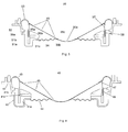
- FIG. 4 shows the cross sectional view of a loudspeaker according to the present invention wherein the second suspension 44 is directly attached to the frame 42 of the loudspeaker 40.
- FIG. 5 shows the cross sectional view of another loudspeaker according to the present invention wherein the second suspension 54 is attached to a soft-magnetic component 51c of the magnet system 51 via an intermediate piece 56 which may be made of metal, plastic or any other suitable materials. Similarly the suspension component in FIG. 5 is also attached to the diaphragm 55 via a second intermediate piece 59. Either of these intermediate pieces may be used, or as shown in FIG. 5 both pieces.
- FIG. 6 shows the cross sectional view of another loudspeaker according to the present invention wherein the second suspension 64 is attached to the soft-magnetic component 61c of the magnet system 61.
- FIG. 7 shows the cross sectional view of another loudspeaker according to the present invention wherein the second suspension 74 is directly attached to a magnet 71a of the magnet system 71.
- the voice coil throw of the invention is potentially much longer than a typical shallow speaker, allowing similar low frequency extension and distortion to a conventional deep loudspeaker geometry. Due to the position of the voice coil attached to the periphery of the diaphragm a significant improvement in directivity and hence power response bandwidth is available over an equivalent conventional geometry loudspeaker.
- FIG. 8 is a graph showing a typical frequency response of the loudspeaker of the present invention comprising a MMX diaphragm. From this figure, it can be seen that the roll-off in the high frequency range although somewhat earlier than in a conventional loudspeaker geometry, is more controlled and smoother for a given diaphragm material. This improvement is appreciated, because an uncontrolled roll-off in the high frequency range usually means the generation of mid and high Q resonance artefacts, which brings unwanted audible ringing and potential distortion increases.
- FIG. 9 illustrates a comparison of off-axis performance (power response) between a conventional geometry loudspeaker and a loudspeaker of the present invention.
- the conventional geometry (a) is approximately 12 dB down in output while a loudspeaker of the present invention (b) is only about 5 dB down, an evident improvement in directivity.
- FIG. 10 demonstrates the broader power response available from a loudspeaker of the present invention over that of a conventional loudspeaker with the same diaphragm diameter and material.
Landscapes
- Physics & Mathematics (AREA)
- Engineering & Computer Science (AREA)
- Acoustics & Sound (AREA)
- Signal Processing (AREA)
- Audible-Bandwidth Dynamoelectric Transducers Other Than Pickups (AREA)
Abstract
Description
- The present invention relates to a loudspeaker and, in particular, a shallow loudspeaker with improved lateral stability of the voice coil.
- The basic components of a conventional loudspeaker include moving parts, such as a voice coil system for converting the electrical input signal into motion, a diaphragm for converting said motion into acoustical output; stationary parts, such as a magnet system for providing a permanent magnetic force for the voice coil and a frame or chassis for supporting the components; suspension devices for connecting the moving parts with the stationary parts, and a terminal board or connector for electrical connection.
- To illustrate the above constitution better, an exemplar conventional loudspeaker is shown in FIG. 1. Here, the
loudspeaker 10 comprises a diaphragm 5, a voice coil system whereincoil windings 7 are wound about acoil carrier 8, amagnet system 1 which comprises a ring-shapedpermanent magnet 1a, a front plate 1b, and abottom yoke 1c. A suspension device 4 connects the voice coil with theframe 2 which is also known to the skilled in the art as chassis, basket, or the like. Theframe 2 not only serves as housing for the loudspeaker, but also provides a firm support to the moving parts: the periphery of the diaphragm 5 is fixed to theframe 2 by way of a second suspension device 3; the suspension device 4 also finds its footing on theframe 2. Thus, the moving parts obtain a certain level of stability when in vibration. - The suspension devices resist lateral movement of the moving assembly, whilst offering a restoring force to any axial movement from the voice coil. As lateral movement is most likely to be problematic at low frequency, where the moving components are likely to be moving as a single body, the suspension components can be seen as simple springs anchoring the moving assembly to the frame. If lateral movement were to happen it would almost certainly be in the form of rotational movement due to the nature of the suspension devices attached around the extremities of the moving components. Such motion would occur around a point defined by the positions of the suspension components. This point is likely to be positioned centrally through the horizontal axis of the loudspeaker and vertically somewhere between the two suspension devices depending on the stiffness of each device and their distance apart.
- The exact position of this centre of rotation can be calculated, however the pertinent point is that the voice coil is likely to be the furthest component away from the centre of rotation, and therefore is likely to move around an ark of rotation relative to the centre of rotation. The distance of the coil away from the centre of rotation can be seen as a multiplying factor of the unwanted rotation of motion, amplifying any rotation at the coil, thus suggesting that small rotation caused for example by a miss aligned diaphragm or suspension component during manufacture, has a high likelihood of causing a coil rub.
- As known to the skilled in the art, in order to achieve good acoustic characteristics (such as a low frequency extension, low distortion and balanced frequency response) for the loudspeaker, a high degree of lateral stability is desired for the diaphragm. One way to fulfil this desire is, according to basic geometric principles, to arrange the two suspension devices as far apart from each other as possible. Taking FIG. 1 as an example, the connection device 3 and suspension device 4 would be positioned as wide part as possible. However, it is easy to see that, such an arrangement generally results in a deep loudspeaker profile.
- Several methods for reducing the depth of loudspeakers have been explored, which include using shallow diaphragm profiles, inverted designs, large voice coils, shallow magnet systems, or a combination of some of these. Most of these designs are still based around the conventional loudspeaker geometry.
- For example,
U.S. patent application No. 2004-0170297 discloses a speaker apparatus with an inverse dome-shaped diaphragm driven at its periphery wherein a suspension may be disposed between the voice coil carrier and the loudspeaker frame in order to support the dome diaphragm. This geometry still falls into the conventional category and provides limited lateral stability for the diaphragm. - Therefore, a compromise usually has to be made between depth reduction and performance where, if a high level of performance is still required to cover a significant audio range, only a token depth reduction can be achieved. Alternatively, sacrifices in terms of performance would be made to allow for a significant reduction in depth.
- Although shallow loudspeaker geometries do exist, in particular with tweeters and midrange speakers, the distance between suspensions in these shallow speakers is typically compressed, or in extreme cases, one of the suspensions is omitted, leaving only a single fixing position on the diaphragm for the suspension, thus reducing the lateral stability of the moving assembly and causing distortion and potential coil rub. This type of loudspeaker is therefore inherently unstable, thus suitable for only small excursion and hence reduced low frequency extension. Though it is possible to fix a suspension device to the voice coil away from the first fixing point, this inevitably adds unwanted depth and diameter to the loudspeaker.
- Thus, there exists a need to provide a new loudspeaker geometry that maintains a high level of lateral stability, whilst reduces the overall depth of the loudspeaker.
- The present invention provides a loudspeaker comprising a diaphragm with three areas: an outer periphery, an intermediate area, and a centre area; a frame which houses the diaphragm; a motor system for providing the driving force to vibrate the diaphragm, said motor system including a magnet system attached to the frame and a voice coil system attached to the diaphragm; a first suspension attached to the frame and the periphery of the diaphragm; and a second suspension attached to either the frame or the magnet system - either directly or through a intermediate piece - and the diaphragm or an intermediate piece. Specifically, the second suspension is attached closer to the centre area of the diaphragm than the voice coil system is.
- The loudspeaker of the present invention has numerous advantages over its conventional counterparts. It allows a significant reduction in depth of the speaker profile. For instance, the depth of the speaker can be reduced by typically the magnet depth of a conventional loudspeaker geometry for a given voice coil size.
- Further, the presence of two suspensions and the locations thereof, especially the location of the second suspension, ensure a maximized space between the suspensions. Thus achieving an excellent lateral stability for the loudspeaker, by moving the voice coil much closer to the centre of any unwanted lateral rotation of the moving parts. The above-mentioned structural advantages, the improved stability in particular, translate into better acoustic performance with respect to current shallow transducer topology: Increased excursion, improved low frequency extension, improved distortion, and improved frequency response balance. Other performance benefits gained from the geometry described in the present invention include better directivity, a smoother high frequency roll off, and an extended power response.
- Moreover, the various parts of the loudspeaker may be positioned more advantageous and closer to one another and therefore may be integrated with one another more easily (e.g., voice coil carrier and diaphragm) than in the case of conventional loudspeakers. Consequently, a reduction in parts count may be attained, which potentially means a simplified production process, and lower manufacturing costs. Additionally, the two suspensions are allowed to be attached to the different sides of the diaphragm, thus further simplifying the manufacture of the loudspeaker.
- The present invention can be better understood with reference to the following drawings and description. The components in the figures are not necessarily to scale, emphasis instead being placed upon illustrating the principals of the invention. Moreover, in the figures, like reference numerous designate corresponding parts throughout the different views.
- FIG. 1
- is a cross sectional view showing a typical conventional loudspeaker geometry;
- FIG. 2
- is a cross sectional view of a loudspeaker according to the present invention wherein a dust cap is attached to a cone-shaped diaphragm covering the orifice in the diaphragm;
- FIG. 3
- is a cross sectional view of another loud-speaker according to the present invention, wherein the diaphragm is of an inverted dome-shape;
- FIG. 4
- is a cross sectional view of another loud-speaker according to the present invention, wherein the second suspension is attached to the frame and wherein and the diaphragm and the voice coil carrier are formed as a single piece;
- FIG. 5
- is a cross sectional view of another loud-speaker according to the present invention wherein the second suspension is attached to a shell pot of the magnet system via an intermediate piece, similarly the second suspension is attached to the diaphragm via another intermediate piece;
- FIG. 6
- is a cross sectional view of another loud-speaker according to the present invention wherein the second suspension is attached directly to the shell pot of the magnet system;
- FIG. 7
- is a cross sectional view of another loud-speaker according to the present invention wherein the second suspension is attached directly to the ring magnet of the magnet system;
- FIG. 8
- is a graph showing the typical frequency response of a loudspeaker according to the present invention for a given diaphragm material MMX;
- FIG. 9
- is a graph showing a comparison of a typical power response for a conventional speaker geometry and that of the present invention, both parts having a common diaphragm material and diameter;
- FIG. 10
- is a graph showing a comparison of the typical off axis performance between a conventional loudspeaker and a loudspeaker according to the present invention, both parts having a common diaphragm material and diameter.
- The present invention is further described in detail with references to the figures illustrating examples of the present invention.
- FIG. 2 depicts a basic geometry of a loudspeaker of the present invention in a cross sectional view. In this figure, the
loudspeaker 20 comprises adiaphragm 25, aframe 22, a motor system having a magnet system 21 and avoice coil system first suspension 23, and asecond suspension 24. - The
diaphragm 25 has an outer periphery 25a, acentre area 25c, and anintermediate area 25b there between. Thediaphragm 25 may be cone-shaped as shown in FIG. 2, or dome-shaped, or more particular, "inverted dome-shaped," as shown in FIG. 3 below. Thecentre area 25c of thediaphragm 25 may comprise a centre orifice 25d as seen in FIG. 2. Additionally, adust protection cap 25e is attached to the front side of thediaphragm 25 for covering the orifice 25d. Thedust protection cap 25e as shown in FIG. 2 or thediaphragm 25 as shown in FIG. 3 may have ahole 25e in theirrespective centre area 25c for manufacturing purposes. Thediaphragm 25 may be made of any material known in the art, such as aluminium, paper, wood, plastic, et cetera. - The
diaphragm 25 is positioned in theframe 22 of theloudspeaker 20. Besides accommodating thediaphragm 25, theframe 22 provides housing and mechanical support for the other components of theloudspeaker 20, such as the motor system and thesuspensions frame 22 may comprise a metal chassis such as an aluminium or steel chassis, or a plastic chassis. - The motor system, which is attached to the
frame 22, for example, by means of cradle, includes a magnet system 21 attached to theframe 22, and avoice coil system diaphragm 25. The magnet system 21 may comprise one oremore magnets 21a typically, but not exclusively, made of neodymium or ferrite, and one or more soft-magnetic components air gap 21d into which the voice coil system is disposed. The magnet system 21 may, in particular, comprise a ring-shapedpermanent magnet 21a, a top plate orcore cap 21b, and ashell pot 21c, thus forming a magnetic circuit with theannular gap 21d between thecore cap 21b and theshell pot 21c. Any other known designs of magnet systems are applicable as well. - The
voice coil system air gap 21d and attached to thediaphragm 25. The voice coil system comprises a voice coil carrier known as a former 27 attached to the outer periphery 25a of thediaphragm 25 andvoice coils 28 wound about thevoice coil carrier 27. Thecoils 28 may be of a round or flat wire type, which may be made of aluminium and/or copper. - A
first suspension 23 is attached to thediaphragm 25 and theframe 22, basically for fixing the periphery 25a of thediaphragm 25 to theframe 22. Asecond suspension 24 is attached, at one end, to thediaphragm 22, and at the other end, to theframe 22. More details about the fixture of thesecond suspension 24 are described in FIG. 4, 5, and 6, below. The fixture of either end can be performed either directly or indirectly, that is, via an intermediate piece wherein the magnet system can serve as an intermediate piece, too. In particular, thesecond suspension 24 is attached to the diaphragm at a point that is closer to thecentre 25c of the diaphragm than the point at which thevoice coil system centre 25c of thediaphragm 25 to theframe 22. - Preferably, the
second suspension 24 is attached to thediaphragm 25 as far away as possible from thefirst suspension 23 which is attached to the outer periphery 25a of thediaphragm 25. Thesecond suspension 24 should ideally be positioned lower than thevoice coil 28. A maximised distance between thefirst suspension 23 and thesecond suspension 24 which may be a spider, such as a corrugated spider ensures a high level of lateral stability, which in turn brings about many stability and acoustic benefits for the loudspeaker either directly or indirectly through other aspects of the geometry. - The
first suspension 23 may be disposed in non-supporting and non-stressing relation to theframe 22 and thediaphragm 25, with thesecond suspension 24 providing support for thediaphragm 25. Thesuspensions first suspension 23 is attached to the front side of thediaphragm 25 while thesecond suspension 24 to the rear side thereof. - Each of the first 23 and the second 24 suspensions would typically be made of a flexible material, such as, though not exclusively, rubber, foam, polymer, woven fabric, or a composite of some of these materials. The
suspensions - As in the conventional way, the various components of the
loudspeaker 20 may be formed individually and interconnected by adhesive joins. For example, thediaphragm 25 and thevoice coil carrier 27 as shown in FIG. 2 are interconnected byadhesive join 29a; thedust cap 25c and the diaphragm are interconnected byadhesive join 29b. - FIG. 3 shows a cross sectional view of another loudspeaker according to the present invention. The components of the
loudspeaker 30 in this figure are the same as those in FIG. 2, except that thediaphragm 35 is of an inverted dome-shape. Basically, an "inverted dome-shaped speaker" has a concave cross section formed by protruding the dome toward the voice coil. - Various components of loudspeakers of the present invention may be formed individually as in the conventional manner. However, the present invention also allows them to be formed as a single piece, thus facilitating the creation of features within components for improving performance and reducing both parts count and the number of necessary joins. For instance, as shown in the cross sectional view of a
loudspeaker 40 in FIG. 4, adiaphragm 45, avoice coil carrier 48, and/or a dust protection cap (having no hole) may be formed as a single piece, eliminating adhesive joins 29a and 29b of FIG. 2. The material used for thediaphragm 45 is, typically, though not exclusively, aluminium. When several components are formed as a single piece, a reduction in parts count is achieved, which potentially means a reduction in moving mass, a simplified production process, and a lower manufacturing cost. - As mentioned earlier, the second suspension may be attached to the frame or to the magnet system, and in case of the later, the second suspension may be attached to different components of the magnet system, such as the magnet component or the soft-magnetic component. FIG. 4 shows the cross sectional view of a loudspeaker according to the present invention wherein the
second suspension 44 is directly attached to theframe 42 of theloudspeaker 40. - FIG. 5 shows the cross sectional view of another loudspeaker according to the present invention wherein the
second suspension 54 is attached to a soft-magnetic component 51c of the magnet system 51 via anintermediate piece 56 which may be made of metal, plastic or any other suitable materials. Similarly the suspension component in FIG. 5 is also attached to the diaphragm 55 via a secondintermediate piece 59. Either of these intermediate pieces may be used, or as shown in FIG. 5 both pieces. - FIG. 6 shows the cross sectional view of another loudspeaker according to the present invention wherein the
second suspension 64 is attached to the soft-magnetic component 61c of the magnet system 61. - FIG. 7 shows the cross sectional view of another loudspeaker according to the present invention wherein the
second suspension 74 is directly attached to a magnet 71a of the magnet system 71. - Lateral stability is greatly increased as the voice coil is generally positioned much closer, or ideally in between the two suspension devices, thereby placing the voice coil intimately with the centre of any potential lateral rotation as described earlier, so suppressing the potential risk of voice coil rub. The voice coil throw of the invention is potentially much longer than a typical shallow speaker, allowing similar low frequency extension and distortion to a conventional deep loudspeaker geometry.
Due to the position of the voice coil attached to the periphery of the diaphragm a significant improvement in directivity and hence power response bandwidth is available over an equivalent conventional geometry loudspeaker. - The acoustic performance of the loudspeaker according to the present invention is better than conventional (shallow) loudspeakers in several aspects. FIG. 8 is a graph showing a typical frequency response of the loudspeaker of the present invention comprising a MMX diaphragm. From this figure, it can be seen that the roll-off in the high frequency range although somewhat earlier than in a conventional loudspeaker geometry, is more controlled and smoother for a given diaphragm material. This improvement is appreciated, because an uncontrolled roll-off in the high frequency range usually means the generation of mid and high Q resonance artefacts, which brings unwanted audible ringing and potential distortion increases.
- Furthermore, FIG. 9 illustrates a comparison of off-axis performance (power response) between a conventional geometry loudspeaker and a loudspeaker of the present invention. As can be seen, at 80° and at a frequency of 4 kHz, the conventional geometry (a) is approximately 12 dB down in output while a loudspeaker of the present invention (b) is only about 5 dB down, an evident improvement in directivity.
- FIG. 10 demonstrates the broader power response available from a loudspeaker of the present invention over that of a conventional loudspeaker with the same diaphragm diameter and material.
- Although examples of the present invention have been described herein above in detail, it is desired, to emphasis that this has not been for the purpose of illustrating the present invention and should not be considered as necessarily limitative of the invention, it being understood that many modifications and variations can be made by those skilled in the art while still practising the invention claimed herein.
Claims (21)
- A loudspeaker comprising:a diaphragm having an outer periphery, an intermediate area, and a centre area;a frame in which the diaphragm being disposed;a motor system for driving the diaphragm, said motor system including a magnet system attached to the frame and a voice coil system attached to the diaphragm;a first suspension being attached to the frame and the outer periphery of the diaphragm and; anda second suspension being attached to the frame and the diaphragm;wherein the second suspension being attached closer to the centre of the diaphragm than the voice coil system.
- The loudspeaker of claim 1 wherein the voice coil system is attached to the outer periphery of the diaphragm.
- The loudspeaker of claim 1 or 2, wherein the voice coil system comprises a voice coil carrier attached to the diaphragm and a voice coil wound around the voice coil carrier.
- The loudspeaker of claim 1, 2, or 3 wherein the diaphragm is cone-shaped.
- The loudspeaker of claim 4 further comprising a centre orifice.
- The loudspeaker of claim 5 further comprising a dust protection cap attached to the diaphragm for covering the centre orifice.
- The loudspeaker of claim 1, 2, or 3 wherein the diaphragm is dome-shaped.
- The loudspeaker of one of the preceding claims
wherein
the second suspension is attached to the frame by means of an intermediate piece. - The loudspeaker of claim 8 wherein the intermediate piece is the magnet system.
- The loudspeaker of one of the preceding claims
wherein the first suspension being disposed in non-supporting and non-stressing relation to the frame and the diaphragm, and the second suspension providing support for the diaphragm. - The loudspeaker of one of the preceding claims
wherein the second suspension is attached to the centre area of the diaphragm. - The loudspeaker of one of the preceding claims
wherein the second suspension is a spider. - The loudspeaker of claim 12 wherein said spider is made from woven fabric.
- The loudspeaker of claim 12 or 13 wherein said spider is corrugated.
- The loudspeaker of one of the preceding claims
wherein said first suspension is made from rubber. - The loudspeaker of one of the preceding claims
wherein said voice coil system comprises a flat wire voice coil. - The loudspeaker of claim 16 wherein said voice coil is made from aluminum wire.
- The loudspeaker of one of the preceding claims
wherein the frame comprises a metal chassis. - The loudspeaker of one of the preceding claims
wherein the magnet system comprises at least one neodymium magnet. - The loudspeaker of one of the preceding claims
wherein the diaphragm has a front side and a rear side and
wherein the first suspension is arranged on the front side of the diaphragm and the second suspension is arranged on the rear side of the diaphragm. - The loudspeaker of one of the preceding claims
wherein said diaphragm is made from aluminum.
Priority Applications (1)
| Application Number | Priority Date | Filing Date | Title |
|---|---|---|---|
| EP20050013378 EP1737269B1 (en) | 2005-06-21 | 2005-06-21 | Shallow loudspeaker |
Applications Claiming Priority (1)
| Application Number | Priority Date | Filing Date | Title |
|---|---|---|---|
| EP20050013378 EP1737269B1 (en) | 2005-06-21 | 2005-06-21 | Shallow loudspeaker |
Publications (2)
| Publication Number | Publication Date |
|---|---|
| EP1737269A1 true EP1737269A1 (en) | 2006-12-27 |
| EP1737269B1 EP1737269B1 (en) | 2012-10-10 |
Family
ID=35207531
Family Applications (1)
| Application Number | Title | Priority Date | Filing Date |
|---|---|---|---|
| EP20050013378 Expired - Lifetime EP1737269B1 (en) | 2005-06-21 | 2005-06-21 | Shallow loudspeaker |
Country Status (1)
| Country | Link |
|---|---|
| EP (1) | EP1737269B1 (en) |
Cited By (5)
| Publication number | Priority date | Publication date | Assignee | Title |
|---|---|---|---|---|
| GB2500718A (en) * | 2012-03-30 | 2013-10-02 | Paul Raymond Knight | Edge- or circumferentially driven planar loudspeaker with Neodymium magnet system |
| DK178826B1 (en) * | 2015-11-03 | 2017-02-27 | Fibona Acoustics Aps | Loudspeaker membrane and low-profile loudspeaker |
| US10917725B2 (en) | 2015-11-03 | 2021-02-09 | Fibona Acoustics Aps | Loudspeaker membrane with curved structure paths |
| CN117041831A (en) * | 2023-08-03 | 2023-11-10 | 东莞市龙韵强电声有限公司 | An ultra-thin speaker unit with a centering support piece placed in the middle of the magnetic circuit |
| CN119562195A (en) * | 2024-12-11 | 2025-03-04 | 广东万昌科技实业有限公司 | A high-fidelity speaker with small diameter and large voice coil and a high-fidelity ultra-thin speaker |
Citations (4)
| Publication number | Priority date | Publication date | Assignee | Title |
|---|---|---|---|---|
| JPH04192800A (en) * | 1990-11-26 | 1992-07-10 | Sharp Corp | Electromechanical converter |
| GB2325373A (en) | 1996-02-29 | 1998-11-18 | Matsushita Electric Industrial Co Ltd | Loudspeaker unit |
| US20030031337A1 (en) | 2001-08-10 | 2003-02-13 | D'hoogh Guido Odilon Maurits | Loudspeaker with a three-dimensional diaphragm |
| EP1478209A2 (en) * | 2003-05-14 | 2004-11-17 | Harman Becker Automotive Systems GmbH | Loudspeaker |
-
2005
- 2005-06-21 EP EP20050013378 patent/EP1737269B1/en not_active Expired - Lifetime
Patent Citations (4)
| Publication number | Priority date | Publication date | Assignee | Title |
|---|---|---|---|---|
| JPH04192800A (en) * | 1990-11-26 | 1992-07-10 | Sharp Corp | Electromechanical converter |
| GB2325373A (en) | 1996-02-29 | 1998-11-18 | Matsushita Electric Industrial Co Ltd | Loudspeaker unit |
| US20030031337A1 (en) | 2001-08-10 | 2003-02-13 | D'hoogh Guido Odilon Maurits | Loudspeaker with a three-dimensional diaphragm |
| EP1478209A2 (en) * | 2003-05-14 | 2004-11-17 | Harman Becker Automotive Systems GmbH | Loudspeaker |
Non-Patent Citations (1)
| Title |
|---|
| PATENT ABSTRACTS OF JAPAN vol. 016, no. 517 (E - 1284) 23 October 1992 (1992-10-23) * |
Cited By (5)
| Publication number | Priority date | Publication date | Assignee | Title |
|---|---|---|---|---|
| GB2500718A (en) * | 2012-03-30 | 2013-10-02 | Paul Raymond Knight | Edge- or circumferentially driven planar loudspeaker with Neodymium magnet system |
| DK178826B1 (en) * | 2015-11-03 | 2017-02-27 | Fibona Acoustics Aps | Loudspeaker membrane and low-profile loudspeaker |
| US10917725B2 (en) | 2015-11-03 | 2021-02-09 | Fibona Acoustics Aps | Loudspeaker membrane with curved structure paths |
| CN117041831A (en) * | 2023-08-03 | 2023-11-10 | 东莞市龙韵强电声有限公司 | An ultra-thin speaker unit with a centering support piece placed in the middle of the magnetic circuit |
| CN119562195A (en) * | 2024-12-11 | 2025-03-04 | 广东万昌科技实业有限公司 | A high-fidelity speaker with small diameter and large voice coil and a high-fidelity ultra-thin speaker |
Also Published As
| Publication number | Publication date |
|---|---|
| EP1737269B1 (en) | 2012-10-10 |
Similar Documents
| Publication | Publication Date | Title |
|---|---|---|
| TWI437894B (en) | Multi function speaker | |
| EP2512155B1 (en) | Low profile loudspeaker transducer | |
| EP1658753B1 (en) | Loudspeaker having a composite diaphragm structure | |
| KR101047549B1 (en) | Multifunction micro speaker | |
| EP2429217A1 (en) | Multifunctional micro-speaker | |
| EP2512153B1 (en) | Loudspeaker magnet assembly | |
| EP2512154B1 (en) | Loudspeaker magnet having a channel | |
| JP2010288099A (en) | Loudspeaker | |
| GB2427095A (en) | Electromagnetic exciter for sounds and vibrations | |
| JPH11355883A (en) | Speaker device | |
| CN101931845A (en) | Multi function micro speaker | |
| CN117560608B (en) | Speakers and speaker boxes | |
| US20070104340A1 (en) | System and Method for Manufacturing a Transducer Module | |
| WO2007086315A1 (en) | Speaker and electronic apparatus and device using the same | |
| EP2512156B1 (en) | Low profile loudspeaker | |
| US20100208934A1 (en) | Speaker device | |
| EP1737269B1 (en) | Shallow loudspeaker | |
| US20180317014A1 (en) | Rear suspension for speaker drivers | |
| KR200454024Y1 (en) | Multifunction micro speaker | |
| US11589167B1 (en) | Multifunctional electromagnetic transducer | |
| KR20080095962A (en) | Electroacoustic conversion unit having the output structure of the same phase bass reversal system with distortion prevention performance | |
| US7787650B2 (en) | Electromagnetic exciter | |
| CN111836175B (en) | Micro loudspeaker | |
| KR100769885B1 (en) | Electronic sound transducer | |
| CN202514066U (en) | Multifunctional mini-size loudspeaker |
Legal Events
| Date | Code | Title | Description |
|---|---|---|---|
| PUAI | Public reference made under article 153(3) epc to a published international application that has entered the european phase |
Free format text: ORIGINAL CODE: 0009012 |
|
| AK | Designated contracting states |
Kind code of ref document: A1 Designated state(s): AT BE BG CH CY CZ DE DK EE ES FI FR GB GR HU IE IS IT LI LT LU MC NL PL PT RO SE SI SK TR |
|
| AX | Request for extension of the european patent |
Extension state: AL BA HR LV MK YU |
|
| 17P | Request for examination filed |
Effective date: 20070601 |
|
| AKX | Designation fees paid |
Designated state(s): AT BE BG CH CY CZ DE DK EE ES FI FR GB GR HU IE IS IT LI LT LU MC NL PL PT RO SE SI SK TR |
|
| 17Q | First examination report despatched |
Effective date: 20090417 |
|
| GRAP | Despatch of communication of intention to grant a patent |
Free format text: ORIGINAL CODE: EPIDOSNIGR1 |
|
| RAP1 | Party data changed (applicant data changed or rights of an application transferred) |
Owner name: HARMAN INTERNATIONAL INDUSTRIES LTD. |
|
| GRAS | Grant fee paid |
Free format text: ORIGINAL CODE: EPIDOSNIGR3 |
|
| GRAA | (expected) grant |
Free format text: ORIGINAL CODE: 0009210 |
|
| AK | Designated contracting states |
Kind code of ref document: B1 Designated state(s): AT BE BG CH CY CZ DE DK EE ES FI FR GB GR HU IE IS IT LI LT LU MC NL PL PT RO SE SI SK TR |
|
| REG | Reference to a national code |
Ref country code: GB Ref legal event code: FG4D |
|
| REG | Reference to a national code |
Ref country code: CH Ref legal event code: EP Ref country code: AT Ref legal event code: REF Ref document number: 579414 Country of ref document: AT Kind code of ref document: T Effective date: 20121015 |
|
| REG | Reference to a national code |
Ref country code: IE Ref legal event code: FG4D |
|
| REG | Reference to a national code |
Ref country code: DE Ref legal event code: R096 Ref document number: 602005036454 Country of ref document: DE Effective date: 20121206 |
|
| PG25 | Lapsed in a contracting state [announced via postgrant information from national office to epo] |
Ref country code: SI Free format text: LAPSE BECAUSE OF FAILURE TO SUBMIT A TRANSLATION OF THE DESCRIPTION OR TO PAY THE FEE WITHIN THE PRESCRIBED TIME-LIMIT Effective date: 20121010 |
|
| REG | Reference to a national code |
Ref country code: NL Ref legal event code: VDEP Effective date: 20121010 |
|
| REG | Reference to a national code |
Ref country code: AT Ref legal event code: MK05 Ref document number: 579414 Country of ref document: AT Kind code of ref document: T Effective date: 20121010 |
|
| REG | Reference to a national code |
Ref country code: LT Ref legal event code: MG4D |
|
| PG25 | Lapsed in a contracting state [announced via postgrant information from national office to epo] |
Ref country code: LT Free format text: LAPSE BECAUSE OF FAILURE TO SUBMIT A TRANSLATION OF THE DESCRIPTION OR TO PAY THE FEE WITHIN THE PRESCRIBED TIME-LIMIT Effective date: 20121010 Ref country code: SE Free format text: LAPSE BECAUSE OF FAILURE TO SUBMIT A TRANSLATION OF THE DESCRIPTION OR TO PAY THE FEE WITHIN THE PRESCRIBED TIME-LIMIT Effective date: 20121010 Ref country code: NL Free format text: LAPSE BECAUSE OF FAILURE TO SUBMIT A TRANSLATION OF THE DESCRIPTION OR TO PAY THE FEE WITHIN THE PRESCRIBED TIME-LIMIT Effective date: 20121010 Ref country code: ES Free format text: LAPSE BECAUSE OF FAILURE TO SUBMIT A TRANSLATION OF THE DESCRIPTION OR TO PAY THE FEE WITHIN THE PRESCRIBED TIME-LIMIT Effective date: 20130121 Ref country code: IS Free format text: LAPSE BECAUSE OF FAILURE TO SUBMIT A TRANSLATION OF THE DESCRIPTION OR TO PAY THE FEE WITHIN THE PRESCRIBED TIME-LIMIT Effective date: 20130210 Ref country code: FI Free format text: LAPSE BECAUSE OF FAILURE TO SUBMIT A TRANSLATION OF THE DESCRIPTION OR TO PAY THE FEE WITHIN THE PRESCRIBED TIME-LIMIT Effective date: 20121010 |
|
| PG25 | Lapsed in a contracting state [announced via postgrant information from national office to epo] |
Ref country code: PL Free format text: LAPSE BECAUSE OF FAILURE TO SUBMIT A TRANSLATION OF THE DESCRIPTION OR TO PAY THE FEE WITHIN THE PRESCRIBED TIME-LIMIT Effective date: 20121010 Ref country code: GR Free format text: LAPSE BECAUSE OF FAILURE TO SUBMIT A TRANSLATION OF THE DESCRIPTION OR TO PAY THE FEE WITHIN THE PRESCRIBED TIME-LIMIT Effective date: 20130111 Ref country code: PT Free format text: LAPSE BECAUSE OF FAILURE TO SUBMIT A TRANSLATION OF THE DESCRIPTION OR TO PAY THE FEE WITHIN THE PRESCRIBED TIME-LIMIT Effective date: 20130211 Ref country code: BE Free format text: LAPSE BECAUSE OF FAILURE TO SUBMIT A TRANSLATION OF THE DESCRIPTION OR TO PAY THE FEE WITHIN THE PRESCRIBED TIME-LIMIT Effective date: 20121010 Ref country code: CY Free format text: LAPSE BECAUSE OF FAILURE TO SUBMIT A TRANSLATION OF THE DESCRIPTION OR TO PAY THE FEE WITHIN THE PRESCRIBED TIME-LIMIT Effective date: 20121010 |
|
| PG25 | Lapsed in a contracting state [announced via postgrant information from national office to epo] |
Ref country code: AT Free format text: LAPSE BECAUSE OF FAILURE TO SUBMIT A TRANSLATION OF THE DESCRIPTION OR TO PAY THE FEE WITHIN THE PRESCRIBED TIME-LIMIT Effective date: 20121010 |
|
| PG25 | Lapsed in a contracting state [announced via postgrant information from national office to epo] |
Ref country code: EE Free format text: LAPSE BECAUSE OF FAILURE TO SUBMIT A TRANSLATION OF THE DESCRIPTION OR TO PAY THE FEE WITHIN THE PRESCRIBED TIME-LIMIT Effective date: 20121010 Ref country code: BG Free format text: LAPSE BECAUSE OF FAILURE TO SUBMIT A TRANSLATION OF THE DESCRIPTION OR TO PAY THE FEE WITHIN THE PRESCRIBED TIME-LIMIT Effective date: 20130110 Ref country code: CZ Free format text: LAPSE BECAUSE OF FAILURE TO SUBMIT A TRANSLATION OF THE DESCRIPTION OR TO PAY THE FEE WITHIN THE PRESCRIBED TIME-LIMIT Effective date: 20121010 Ref country code: DK Free format text: LAPSE BECAUSE OF FAILURE TO SUBMIT A TRANSLATION OF THE DESCRIPTION OR TO PAY THE FEE WITHIN THE PRESCRIBED TIME-LIMIT Effective date: 20121010 Ref country code: SK Free format text: LAPSE BECAUSE OF FAILURE TO SUBMIT A TRANSLATION OF THE DESCRIPTION OR TO PAY THE FEE WITHIN THE PRESCRIBED TIME-LIMIT Effective date: 20121010 |
|
| PLBE | No opposition filed within time limit |
Free format text: ORIGINAL CODE: 0009261 |
|
| STAA | Information on the status of an ep patent application or granted ep patent |
Free format text: STATUS: NO OPPOSITION FILED WITHIN TIME LIMIT |
|
| PG25 | Lapsed in a contracting state [announced via postgrant information from national office to epo] |
Ref country code: RO Free format text: LAPSE BECAUSE OF FAILURE TO SUBMIT A TRANSLATION OF THE DESCRIPTION OR TO PAY THE FEE WITHIN THE PRESCRIBED TIME-LIMIT Effective date: 20121010 Ref country code: IT Free format text: LAPSE BECAUSE OF FAILURE TO SUBMIT A TRANSLATION OF THE DESCRIPTION OR TO PAY THE FEE WITHIN THE PRESCRIBED TIME-LIMIT Effective date: 20121010 |
|
| 26N | No opposition filed |
Effective date: 20130711 |
|
| REG | Reference to a national code |
Ref country code: DE Ref legal event code: R097 Ref document number: 602005036454 Country of ref document: DE Effective date: 20130711 |
|
| PG25 | Lapsed in a contracting state [announced via postgrant information from national office to epo] |
Ref country code: MC Free format text: LAPSE BECAUSE OF FAILURE TO SUBMIT A TRANSLATION OF THE DESCRIPTION OR TO PAY THE FEE WITHIN THE PRESCRIBED TIME-LIMIT Effective date: 20121010 |
|
| REG | Reference to a national code |
Ref country code: CH Ref legal event code: PL |
|
| REG | Reference to a national code |
Ref country code: IE Ref legal event code: MM4A |
|
| PG25 | Lapsed in a contracting state [announced via postgrant information from national office to epo] |
Ref country code: IE Free format text: LAPSE BECAUSE OF NON-PAYMENT OF DUE FEES Effective date: 20130621 Ref country code: LI Free format text: LAPSE BECAUSE OF NON-PAYMENT OF DUE FEES Effective date: 20130630 Ref country code: CH Free format text: LAPSE BECAUSE OF NON-PAYMENT OF DUE FEES Effective date: 20130630 |
|
| REG | Reference to a national code |
Ref country code: FR Ref legal event code: PLFP Year of fee payment: 11 |
|
| PG25 | Lapsed in a contracting state [announced via postgrant information from national office to epo] |
Ref country code: TR Free format text: LAPSE BECAUSE OF FAILURE TO SUBMIT A TRANSLATION OF THE DESCRIPTION OR TO PAY THE FEE WITHIN THE PRESCRIBED TIME-LIMIT Effective date: 20121010 |
|
| PG25 | Lapsed in a contracting state [announced via postgrant information from national office to epo] |
Ref country code: HU Free format text: LAPSE BECAUSE OF FAILURE TO SUBMIT A TRANSLATION OF THE DESCRIPTION OR TO PAY THE FEE WITHIN THE PRESCRIBED TIME-LIMIT; INVALID AB INITIO Effective date: 20050621 Ref country code: LU Free format text: LAPSE BECAUSE OF NON-PAYMENT OF DUE FEES Effective date: 20130621 |
|
| PGFP | Annual fee paid to national office [announced via postgrant information from national office to epo] |
Ref country code: GB Payment date: 20150629 Year of fee payment: 11 Ref country code: DE Payment date: 20150629 Year of fee payment: 11 |
|
| PGFP | Annual fee paid to national office [announced via postgrant information from national office to epo] |
Ref country code: FR Payment date: 20150617 Year of fee payment: 11 |
|
| REG | Reference to a national code |
Ref country code: DE Ref legal event code: R119 Ref document number: 602005036454 Country of ref document: DE |
|
| GBPC | Gb: european patent ceased through non-payment of renewal fee |
Effective date: 20160621 |
|
| REG | Reference to a national code |
Ref country code: FR Ref legal event code: ST Effective date: 20170228 |
|
| PG25 | Lapsed in a contracting state [announced via postgrant information from national office to epo] |
Ref country code: FR Free format text: LAPSE BECAUSE OF NON-PAYMENT OF DUE FEES Effective date: 20160630 Ref country code: DE Free format text: LAPSE BECAUSE OF NON-PAYMENT OF DUE FEES Effective date: 20170103 |
|
| PG25 | Lapsed in a contracting state [announced via postgrant information from national office to epo] |
Ref country code: GB Free format text: LAPSE BECAUSE OF NON-PAYMENT OF DUE FEES Effective date: 20160621 |
|
| P01 | Opt-out of the competence of the unified patent court (upc) registered |
Effective date: 20230527 |