EP1737245A1 - Method of illuminating a projecting imager, corresponding system and projector - Google Patents
Method of illuminating a projecting imager, corresponding system and projector Download PDFInfo
- Publication number
- EP1737245A1 EP1737245A1 EP06115180A EP06115180A EP1737245A1 EP 1737245 A1 EP1737245 A1 EP 1737245A1 EP 06115180 A EP06115180 A EP 06115180A EP 06115180 A EP06115180 A EP 06115180A EP 1737245 A1 EP1737245 A1 EP 1737245A1
- Authority
- EP
- European Patent Office
- Prior art keywords
- colour base
- image
- diodes
- secondary colour
- base
- Prior art date
- Legal status (The legal status is an assumption and is not a legal conclusion. Google has not performed a legal analysis and makes no representation as to the accuracy of the status listed.)
- Withdrawn
Links
Images



Classifications
-
- G—PHYSICS
- G03—PHOTOGRAPHY; CINEMATOGRAPHY; ANALOGOUS TECHNIQUES USING WAVES OTHER THAN OPTICAL WAVES; ELECTROGRAPHY; HOLOGRAPHY
- G03B—APPARATUS OR ARRANGEMENTS FOR TAKING PHOTOGRAPHS OR FOR PROJECTING OR VIEWING THEM; APPARATUS OR ARRANGEMENTS EMPLOYING ANALOGOUS TECHNIQUES USING WAVES OTHER THAN OPTICAL WAVES; ACCESSORIES THEREFOR
- G03B21/00—Projectors or projection-type viewers; Accessories therefor
- G03B21/14—Details
-
- H—ELECTRICITY
- H04—ELECTRIC COMMUNICATION TECHNIQUE
- H04N—PICTORIAL COMMUNICATION, e.g. TELEVISION
- H04N9/00—Details of colour television systems
- H04N9/12—Picture reproducers
- H04N9/31—Projection devices for colour picture display, e.g. using electronic spatial light modulators [ESLM]
- H04N9/3141—Constructional details thereof
- H04N9/315—Modulator illumination systems
- H04N9/3155—Modulator illumination systems for controlling the light source
Definitions
- the invention relates to the field of image projection.
- the invention relates to an illumination system for an imager (also called micro-display) in a front or overhead video projector.
- an illumination system 10 lighting an imager 11 is implemented.
- the illumination system 10 comprises;
- the illumination source 100 uses a light beam 101 to light the coloured wheel 107 placed at the input of the rectangular guide 102, at the focus of the elliptical reflector of the source 100.
- the rectangular guide 102 is used to convert the circular section of the lighting beam into a rectangular section and make the beam spatially uniform.
- the output of the guide 102 is displayed on the imager 11 via the system of relay lenses, of which there are at least two, but often three or four.
- the illumination system with coloured wheel is replaced by a system based on LEDs (light-emitting diodes).
- the green, blue and red LEDs are switched on sequentially to create a saturated colour illumination beam that is green, blue and red in turn.
- white, magenta, cyan or yellow beams can also be provided.
- the coloured beams of each colour are of fixed duration, and independent of the projected image.
- the imager modulates the colour of each pixel according to the image in a predetermined colour base.
- the object of the invention is to overcome these drawbacks in the prior art.
- the object of the invention is to optimize energy consumption while allowing good quality images to be projected.
- the invention proposes a method of illuminating an imager for projecting images, implementing light-emitting diodes of different colours, the diodes being designed to provide a beam illuminating the imager.
- the method comprises:
- the secondary colour base comprises at least one secondary colour corresponding to a mixture of two primary colours.
- the secondary colour base comprises three colours.
- the step for dynamically controlling the diodes comprises a step for controlling the on time of the diodes and/or their light intensity according to the secondary colour base.
- the step for dynamically controlling the diodes comprises a step for selecting the diodes according to the secondary colour base.
- each image is received in a colour base, called a primary colour base, the primary colour base being distinct from the secondary colour base, the step for determining a colour base comprising a step for converting each image from the primary colour base to the secondary colour base.
- the step for determining a colour base comprises a step for calculating an area encompassing at least 90% of the pixels of the images of the set, the colour base being determined according to the area.
- the area encompasses 100% of the pixels of the images of the set.
- the area forms a polygon.
- each image is received in the secondary colour base
- the step for determining a colour base comprising a step for receiving data representative of the secondary colour base
- the set comprises a single image.
- the invention also relates to an illumination system intended to light an imager for projecting images and comprising light-emitting diodes of different colours, the diodes being designed to provide a beam illuminating the imager.
- the system is noteworthy in that, for a set of at least one image, it comprises:
- the invention also relates to an image projector comprising:
- the main principle of the invention is therefore based on a dynamic management of the illumination beam, the colours of which (nature and/or duration and/or selection of LEDs) depend on each image projected.
- Figure 2 is a highly schematic block diagram of an overhead projector 2 according to a first embodiment of the invention.
- the projector 2 comprises:
- the lens 21, the mirrors 22 and 23 and the screen 24, and their arrangement are well known to those skilled in the art and are not described in any more detail.
- FIG 3 illustrates in detail the illumination system 20 with transmissive imager and which comprises:
- the LED array comprises red, green or blue LEDs.
- the red, green or blue LEDs When the red, green or blue LEDs are switched on in turn, they respectively produce sub-beams of the beam 202 that are respectively red, green and blue.
- the distribution of the LEDs on the array 200 is such that the lighting of the imager by each of the red, green and blue sub-beams is substantially uniform.
- the number of the LEDs of each colour depends on the respective efficiency of these LEDs and is such that the sub-beams have a similar intensity.
- These LEDs are, for example, monochrome power LEDs produced by Osram ® or LumiLeds ®.
- the number of LEDs of each colour depends on the luminance of each of the LEDs and/or of the sensitivity of the human eye to each of the colours. It is possible, for example, to have a uniform distribution of eight green LEDs, four red LEDs and four blue LEDs.
- Figure 4 illustrates the controller 210 in detail.
- the controller 210 comprises, interlinked by an address and data bus 45:
- the input/output interface 44 transmits the LED commands to the driver 213 and the commands and the data corresponding to the images to be projected to the driver 214.
- register used in the description denotes, in each of the memories mentioned, both a small capacity memory area (a few bits) and a large capacity memory area (enabling an entire program or all the data representative of an image to be stored).
- the ROM memory 41 comprises in particular:
- the ROM memory 41 comprises data representative of predetermined secondary colour bases.
- the random access memory 42 comprises in particular:
- Figure 5 illustrates a management algorithm for the drivers 213 and 214 implemented by the controller 210.
- the algorithm starts with an initialization step 50 during which the various parameters and useful data are initialized.
- the controller waits for then receives data 421 representative of an image to be projected, or frame 61, this image being encoded in a primary colour base (typically red, green and blue).
- a primary colour base typically red, green and blue
- the microprocessor 40 determines a new colour base dependent on the image received and called a secondary colour base.
- This secondary colour base corresponds to a triangle 71 covering an area 72 of a gamut comprising each of the pixels of the image and represented, by way of illustration, in Figure 7.
- the area 72 is inscribed in the triangle 71, the corners of which are the points 710, 711, and 712 and which then constitute the new secondary colour base in which all the pixels of the area 72 can be expressed.
- all the pixels of the area 72 can be expressed with positive coefficients in the secondary colour base (negative coefficients corresponding to points outside the triangle concerned).
- the saturated red, green and blue colours are respectively represented by points 700, 702 and 701.
- the triangle 70 having for corners the points 700 to 702 covers the range of colours that can be obtained.
- the point 710 corresponds to a mixture of red and green and is therefore located on the segment linking the points 700 and 702.
- the points 712 and 711 correspond to a mixture of blue and green and are therefore placed on the segment linking the points 701 and 702.
- the controller 210 searches for the triangle 71 of maximum compactness (the compactness being calculated by obtaining the ratio between the area of the triangle 71 and its perimeter squared).
- Figure 8 illustrates the secondary colour base corresponding to a frame 62 received by the controller during the step 51 and determined during the step 52.
- This new base corresponds to a triangle 81 covering an area 82 of a gamut comprising each of the pixels of the frame 82.
- the area 82 is inscribed in the triangle 81 having for corners the points 810, 811, and 812 which then constitute the new colour base in which all the pixels of the area 82 can be expressed.
- the points 810 and 812 correspond to a mixture of red, green and blue and are therefore not on the edges of the triangle having for corners the points 700 to 702 associated with the primary colours.
- the point 811 corresponds to a mixture of blue and red.
- a number of triangles (represented for example by the coordinates of their corners or the equations defining their sides) included in the triangle 70 are determined and stored, with, preferably, their compactness and the data concerning the percentage of primary colour associated with each of its corners.
- the microcontroller 210 checks for all the predetermined triangles that each pixel of the image received (the pixels being represented symbolically by black dots) is in the predetermined triangle concerned, then selects the triangle that has the greater compactness. It is always possible to find such a triangle, the triangles 72 and 82 always comprising all the pixels.
- the microcontroller drags along the sides of the triangle, progressively or by dichotomy, each corner to determine a triangle and checks whether all the pixels of the image are contained in the duly determined triangle. If all the pixels of the image are effectively contained in the triangle, the process is repeated by trying to reduce the compactness or the size of the triangle, otherwise it is stopped (if the triangles are determined by progressively dragging the sides) or repeated by increasing the compactness of the triangle (if the triangles are determined by dichotomic dragging of the sides). Generally, the repetitions stop after a predetermined maximum number, and/or when an appropriate triangle compactness is less than a predetermined compactness and/or when the compactness difference between an appropriate triangle and a triangle that is inappropriate is less than a predetermined value.
- the corners of the triangle 71 are chosen on the three sides of the triangle 72 (the corners of the triangle 71 being on three separate sides) or on two separate sides of the triangle 72. According to other variants, the corners of the triangle 71 are chosen outside the sides of the triangle 72 (for example, by distorting the triangle 72 homothetically, or by retaining one or two corners of the triangle 71 on one or two sides of the triangle 72, the third corner of the triangle 71 being placed inside the triangle 72).
- a quality criterion is provided and, during the step 52, only the triangles that do not cover a predetermined percentage of pixels of the image (typically at least 90%, for example 90%, 95%, 99%, 99.9%) are rejected.
- This variant allows certain isolated pixels not to be considered and therefore provides a saving in light power.
- the microcontroller 210 encodes each of the pixels according to the duly determined triangle.
- all the pixels are not in the triangle 71 (respectively 81), these pixels are associated with a nearby pixel corresponding to an approximate colour.
- This pixel is, for example, located on one of the sides of the triangle 71 (respectively 81), preferably as near as possible to or on the straight line linking the pixel concerned to the centre of the triangle 72 (respectively 82).
- the controller in order to simplify the search for a triangle encompassing all the pixels of a frame and/or the check that all the pixels of this frame belong to a determined triangle, the controller first determines a convex envelope linking the peripheral pixels.
- This envelope comprises all the pixels by definition and it is sufficient to search for a triangle encompassing the peripheral pixels and/or check that the peripheral pixels are contained in the determined triangle for the triangle search and/or the check to be valid for all the pixels of the image.
- the controller determines and transmits control data 423 to the LED driver 213 according to the secondary colour base.
- the control data 423 specifies the on time and/or intensity of the LEDs for each colour in each frame.
- the controller also transmits the data 422 representative of the image encoded according to the secondary colour base to the imager driver 214 which in turn transmits it to the imager 205.
- step 50 is repeated.
- Figure 6 gives an example of dynamic illumination management for two successive images corresponding to two frames 61 and 62, the LED driver 213 controlling the on time of each LED according to the secondary colour base.
- Each of the frames 61 and 62 is divided into three time slots, respectively 610 to 612 and 620 to 622.
- Each of the lines 600 to 604 illustrates the management of the colours over time, and more specifically:
- the three corresponding time slots are mostly respectively red, green and blue, but can include an unsaturated part according to the calculation of the step 51, as illustrated on the line 601.
- Figure 6 corresponds to a calculation of the step 51 having determined that the area 72 of the pixels corresponding to the frame 61 is inscribed in a triangle having for corners the points 710, 711 and 712 respectively corresponding to unsaturated colours of type:
- the or each red LED will be on throughout the time slot and the or each green LED will be on for 25% of the time which gives the average as represented on the line 600.
- the or each green (respectively blue) LED will be on throughout the duration of the time slot and the or each blue (respectively green) LED will be on for 25% (respectively 33%) of the time.
- the step 51 has determined that the area 92 of the pixels is inscribed in a triangle having for corners the points 810, 811 and 812 respectively corresponding to unsaturated colours of type:
- the or each red LED will be on throughout the duration of the time slot and the blue and green LEDs will be on respectively 5% and 25% of the time which gives the average as represented on the line 600.
- the or each green (respectively blue) LED will be on throughout the duration of the time slot, the or each blue (respectively red) LED will be on for 33% (respectively 25%) of the time and the or each red LED will be on for 2% of the time (respectively the or each green LED will be off).
- the or each corresponding LED is switched on throughout the time slot.
- the driver 213 controls the intensity of the supply current to the LEDs to vary the transmitted light power.
- Figure 9 represents a curve 92 giving the relative light intensity 91 (Y axis) according to the controlling electrical intensity 90 (expressed in mA on the X axis).
- the driver 213 thus receives, from the controller 210, the relative light intensity for each LED colour and for the three time slots of a frame (for example, for the time slot 610: 1 for red, 0.33 for green and 0 for blue).
- the driver 213 converts them into a light intensity control according to time and the or each LED concerned (for example via a conversion table and/or by calculation (in particular in the roughly linear part of the curve 92 corresponding to intensity values 90 less than 5 mA according to the example illustrated in Figure 9)).
- the driver 213 can also switch on only some of the LEDs of this colour (for example, if the array 200 includes 30 green LEDs, to obtain 33% green in the time slot 610, the driver 213 can request the switching on of a maximum of 10 green LEDs, the 20 other green LEDs remaining off).
- the driver 213 can also mix the two methods of modulating the light intensity of a colour and of partially switching on the LEDs of this colour (for example, if the array 200 includes 30 green LEDs, to obtain 33% green in the time slot 610, the driver 213 can request the switching on with 50% of the maximum intensity of 20 green LEDs, the 10 other green LEDs remaining off).
- the duration of the light pulses transmitted by the LEDs and/or their light intensity is adjusted frame by frame according to the secondary colour base.
- the time and/or the energy of the coloured LEDs can vary from one image to the next and different colour LEDs can be switched on at the same time.
- the illumination source is very flexible and is optimized to obtain a better quality projected image and/or reduce the overall energy consumption (the LEDs being on for a shorter time and/or being powered with a lesser electrical intensity).
- the images received by the controller are already encoded according to a secondary colour base.
- Data representative of the secondary colour base is also received by the controller.
- the images are, in effect, encoded according to the secondary colour base (according to any one of the methods described previously), for example, after the encoding operation, or during the operation for storing on any medium, or even on sending the images to the controller.
- the means of determining the secondary colour base can advantageou sly be transferred to a remote device, the duly encoded images being able to be used by a number of image display systems (in particular by projectors including an illumination source with or without LEDs).
- the means of determining the secondary colour base can also be transferred to any dedicated equipment inside the projector (for example, in the image reception means).
- the controller waits for then receives the data representative of an image in the secondary colour base dependent on the image received or a set of several images. It also receives the data representative of the secondary colour base.
- the data representative of the base is, for example, a code specific to several possible bases pre-stored in the memory of the controller, possibly downloaded in advance, or the coordinates of this secondary colour base in a primary colour base.
- step 54 for transmitting the data to the LED driver 213 and the image encoded according to the secondary colour base to the imager driver 214 which in turn transmits it to the imager 205.
- This step is similar to the step 54 illustrated by Figure 5, so it carries the same reference and will not be described in any further detail.
- the invention is compatible with any type of projector (in particular front or overhead projectors) comprising at least one imager lit by a sequentially coloured beam from coloured LEDs.
- projector in particular front or overhead projectors
- any type of projector comprising at least one imager lit by a sequentially coloured beam from coloured LEDs.
- Those skilled in the art can also adapt the invention to any type of mechanical and/or optical structure using the coloured LEDs. They can, in particular, vary the number of LEDs of each colour (for example from one LED of each colour (high power LED) to more than ten LEDs of each colour).
- the positioning of the LEDs in the illumination system can vary: they can be in a flat monolithic array as illustrated by Figure 3 or be associated with a number of monochrome LED arrays (for example, three respectively green, blue and red LED arrays) on one and the same plane or not (the structure possibly comprising dichroic return mirrors, enabling beams of different colours to be combined into a single beam illuminating the or each imager) or even remote from the imager, the coloured beams being transmitted to the or each imager via appropriate optical systems (for example, via optical fibres).
- monochrome LED arrays for example, three respectively green, blue and red LED arrays
- the structure possibly comprising dichroic return mirrors, enabling beams of different colours to be combined into a single beam illuminating the or each imager
- the coloured beams being transmitted to the or each imager via appropriate optical systems (for example, via optical fibres).
- the invention is also compatible with illumination systems comprising LEDs of different colours, for example cyan or yellow, not necessarily red, green or blue, or even comprising green, blue or red LEDs of different wavelengths (for example green LEDs at 520 nm and 560 nm, and/or blue LEDs at 440 nm a nd 460 nm, and/or red LEDs at 600 nm and 630 nm).
- illumination systems comprising LEDs of different colours, for example cyan or yellow, not necessarily red, green or blue, or even comprising green, blue or red LEDs of different wavelengths (for example green LEDs at 520 nm and 560 nm, and/or blue LEDs at 440 nm a nd 460 nm, and/or red LEDs at 600 nm and 630 nm).
- illumination systems comprising LEDs of different colours, for example cyan or yellow, not necessarily red, green or blue, or even comprising green, blue or red LEDs of different wavelengths (for example green LEDs
- the determination of the secondary colour base and the encoding of the images in this base takes into account the characteristics of the LEDs (implemented when the means of determining the secondary colour base are associated with the illumination means or possible when the means of determining the secondary colour base and the encoding means are remote, in the case of images encoded outside the LED control means), not necessarily red, green or blue respectively associated with a single wavelength since the range of possible colours is greater (thus, for example, a triangle is defined which comprises a predetermined percentage of pixels of an image in the polygon representative of the LEDs (colours and associated power) forming the illumination means).
- all the colours resulting from the sum of a certain quantity and/or type of blue, green and/or red are obtained by switching on (via the LED driver) the selected LEDs for an appropriate time and/or appropriate intensity.
- Figure 11 presents a gamut according to this variant of the invention, associated with a system comprising green LEDs 1113 and 702 at 520 nm and 560 nm, blue LEDs 701 and 1114 at 440 nm and 460 nm and red LEDs 700 at a single wavelength, for example, the primary colour base is associated with the green LEDs 702 at 560 nm, the blue LEDs 701 at 440 nm and the red LEDs 700.
- the secondary colour base comprises, for example, the green 1113 at 520 nm, the blue 701 at 440 nm and the red 700 that corresponds to a triangle having for corners the points 1113, 701, and 700; then, for a second given image or a second, less saturated, set of images (corresponding to the set of pixels 1117 illustrated diagrammatically), the secondary colour base comprises, for example:
- the invention is not limited to the case where the secondary colour base comprises only three colours, but can be extended to secondary colour bases comprising more than three colours (for example, four, five, six, etc.).
- the secondary colour base can comprise p colours (p being, for example, three, four, five, six, etc.).
- p being, for example, three, four, five, six, etc.
- to determine the secondary colour base instead of defining a triangle associated with the secondary colour base, a polygon with p corners is defined, each of the corners representing an LED colour or a mixture of LED colours, the polygon encompassing all or some (typically at least 90%) of the pixels of an image or a set of images.
- the number of colours in the secondary colour base can also vary dynamically from one image to the next.
- the step for determining the secondary colour base comprises a step for selecting a polygon, the corners of which correspond to an LED colour; according to this variant, the selection step comprises a step for checking a predetermined condition. According to this condition, each polygon that is a candidate for selection comprises all the pixels (or, according to a variant, at least a predetermined quantity, for example, 90% of pixels).
- the selection step is completed by the choice of a polygon, the corners of which specify the secondary colour base, out of the polygon or polygons that satisfy the predetermined condition by, where appropriate, taking into account their compactness (a compactness being preferred) and/or, if appropriate, the percentage of pixels covered by the polygon (a high percentage being preferred).
- the invention is by no means limited to the case where the LED control system is as described previously, but can, by contrast, be extended to any system performing an analysis of one or more images to determine an area of the colour gamut comprising a predetermined percentage of pixels of the or each image concerned and capable of being covered by the LEDs.
- the corresponding secondary colour base can, advantageously, be determined, according to the invention, over the set of these images or over a limited number of these images, even just one of these images.
- the secondary colour base can advantageously be determined at regular intervals (for example, every second, or every n images (n being, for example, 2, 5, 12, 24, etc.) or on an abrupt variation of the content of an image (identified, for example, by performing a correlation between two consecutive images of a stream of frames received) or even in a way synchronized on intra-encoded images (in an MPEG2 or MPEG4 stream, for example) (the determination of the secondary colour base being done from intra-encoded images, the predictive or bipredictive images using the same secondary colour base as that associated with the intra image corresponding to them).
- the secondary colour base is determined for certain images (for example as indicated above) from the content of these images, and the secondary colour base is determined for the subsequent images by simply checking that a predetermined percentage of pixels in these images can be encoded with positive coordinates in the secondary colour base determined previously. If they can, the subsequent images are encoded in the secondary colour base determined previously. If not, the subsequent images are either encoded with this secondary colour base, certain pixels capable of being encoded approximately, or a new colour base is determined from the first subsequent image that does not satisfy the minimum percentage of pixels condition that can be encoded with the secondary colour base determined previously.
- the invention is also compatible with a secondary colour base that comprises more than three elements and, in particular, that comprises white (obtained, for example, with a white light or by superimposing several lightings each associated with a primary colour).
- the invention is also compatible with any type of imager ( or micro-display); thus, it can be applied not only to projectors with transmissive LCD (Liquid Crystal Display), but also to projectors with DMD (Digital Micromirror Device produced by Texas Instruments ®) type imagers or LCOS (Liquid Crystal On Silicon) type imagers (those skilled in the art incorporating the appropriate optical elements (polarisers, lenses, mirrors, etc.) between the illumination source and the imager).
- DMD Digital Micromirror Device produced by Texas Instruments ®
- LCOS Liquid Crystal On Silicon
Landscapes
- Engineering & Computer Science (AREA)
- Multimedia (AREA)
- Signal Processing (AREA)
- Physics & Mathematics (AREA)
- General Physics & Mathematics (AREA)
- Control Of Indicators Other Than Cathode Ray Tubes (AREA)
- Controls And Circuits For Display Device (AREA)
- Projection Apparatus (AREA)
- Video Image Reproduction Devices For Color Tv Systems (AREA)
Abstract
- a step for receiving each image of the set;
- a step for determining a colour base dependent on the set of at least one image, called a secondary colour base; and
- a step for dynamically controlling the diodes according to said secondary colour base.
Description
- The invention relates to the field of image projection.
- More specifically, the invention relates to an illumination system for an imager (also called micro-display) in a front or overhead video projector.
- According to the state of the art, as illustrated by Figure 1, an
illumination system 10 lighting animager 11 is implemented. - Conventionally, the
illumination system 10 comprises; - an
illumination source 100 with elliptical reflector, - a
coloured wheel 107; - a
rectangular guide 102; and - a system of
several relay lenses 104 to 106. - The
illumination source 100 uses alight beam 101 to light thecoloured wheel 107 placed at the input of therectangular guide 102, at the focus of the elliptical reflector of thesource 100. Therectangular guide 102 is used to convert the circular section of the lighting beam into a rectangular section and make the beam spatially uniform. The output of theguide 102 is displayed on theimager 11 via the system of relay lenses, of which there are at least two, but often three or four. - According to another state of the art disclosed, for example, in
US patent 6224216 , the illumination system with coloured wheel is replaced by a system based on LEDs (light-emitting diodes). The green, blue and red LEDs are switched on sequentially to create a saturated colour illumination beam that is green, blue and red in turn. In certain configurations, white, magenta, cyan or yellow beams can also be provided. In all cases, the coloured beams of each colour are of fixed duration, and independent of the projected image. The imager modulates the colour of each pixel according to the image in a predetermined colour base. - These techniques present the drawback of not optimally managing energy consumption.
- The object of the invention is to overcome these drawbacks in the prior art.
- More particularly, the object of the invention is to optimize energy consumption while allowing good quality images to be projected.
- To this end, the invention proposes a method of illuminating an imager for projecting images, implementing light-emitting diodes of different colours, the diodes being designed to provide a beam illuminating the imager. According to the invention, for a set of at least one image, the method comprises:
- a step for receiving each image of the set;
- a step for determining a colour base dependent on the set of at least one image, called a secondary colour base;
- a step for dynamically controlling the diodes according to said secondary colour base.
- According to an advantageous characteristic, the secondary colour base comprises at least one secondary colour corresponding to a mixture of two primary colours.
- According to a particular characteristic, the secondary colour base comprises three colours.
- According to advantageous characteristics, the step for dynamically controlling the diodes comprises a step for controlling the on time of the diodes and/or their light intensity according to the secondary colour base.
- According to a particular characteristic, the step for dynamically controlling the diodes comprises a step for selecting the diodes according to the secondary colour base.
- Preferably, in the step for receiving the set of at least one image, each image is received in a colour base, called a primary colour base, the primary colour base being distinct from the secondary colour base, the step for determining a colour base comprising a step for converting each image from the primary colour base to the secondary colour base.
- According to an advantageous characteristic, the step for determining a colour base comprises a step for calculating an area encompassing at least 90% of the pixels of the images of the set, the colour base being determined according to the area.
- According to a particular characteristic, the area encompasses 100% of the pixels of the images of the set.
- Advantageously, the area forms a polygon.
- According to another preferred characteristic, in the step for receiving the set of at least one image, each image is received in the secondary colour base, the step for determining a colour base comprising a step for receiving data representative of the secondary colour base.
- According to a particular characteristic, the set comprises a single image.
- The invention also relates to an illumination system intended to light an imager for projecting images and comprising light-emitting diodes of different colours, the diodes being designed to provide a beam illuminating the imager. According to the invention, the system is noteworthy in that, for a set of at least one image, it comprises:
- means of receiving each image of the set;
- means of determining a colour base dependent on the set of at least one image, called a secondary colour base;
- means of dynamically controlling the diodes according to the secondary colour base.
- The invention also relates to an image projector comprising:
- at least one projection lens;
- at least one imager;
- at least one illumination system as described previously according to the invention and intended to light said imager.
- The invention will be better understood, and other features and advantages will become apparent from reading the description that follows, the description referring to the appended drawings in which:
- Figure 1 illustrates an illumination system known per se;
- Figure 2 is an extremely schematic diagram of an overhead projector according to an embodiment of the invention;
- Figure 3 presents an illumination system implemented in the overhead projector of Figure 2;
- Figure 4 illustrates means of controlling the illumination system of Figure 3;
- Figure 5 presents an illumination management algorithm implemented in the control means of Figure 4;
- Figure 6 gives an example of dynamic illumination management according to the invention;
- Figures 7, 8 and 11 respectively illustrate a particular case of colour management in an image according to the invention;
- Figure 9 presents the control of the light intensity in an LED of the system of Figure 3; and
- Figure 10 presents a variant of the illumination management algorithm implemented in the control means of Figure 4.
- The main principle of the invention is therefore based on a dynamic management of the illumination beam, the colours of which (nature and/or duration and/or selection of LEDs) depend on each image projected.
- Figure 2 is a highly schematic block diagram of an
overhead projector 2 according to a first embodiment of the invention. - The
projector 2 comprises: - an
illumination system 20; - a lens 21 receiving an
illumination beam 26 created by theillumination system 20 and producing abeam 25; - an
overhead projection screen 24 lit by thebeam 25; and - two folding mirrors 22 and 23 folding the
beam 25 and being used to reduce the depth of theprojector 2. - The lens 21, the
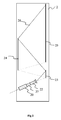
mirrors screen 24, and their arrangement are well known to those skilled in the art and are not described in any more detail. - Figure 3 illustrates in detail the
illumination system 20 with transmissive imager and which comprises: - an array of illuminating
LEDs 200; - a
lens 201 collim ating the beams transmitted by each of the LEDs of thearray 200 to produce abeam 202 that is substantially collimated (a beam being in this case substantially collimated if it does not diverge by ±6° in relation to its optical axis); - a
convergence lens 203; - an
imager 205 of the transmissive type (transmissive LCD) roughly perpendicular to the axis of thebeam 202, lit by thebeam 202 having passed through thelens 203, theimager 205 producing animaging beam 27; - an
LED driver 213 which manages the switching on and off of each of the LEDs of thearray 200 via alink 215; - an
imager driver 214 which controls theimager 205 via alink 216; and - a
controller 210 which controls thedrivers respective links link 30. - The LED array comprises red, green or blue LEDs. When the red, green or blue LEDs are switched on in turn, they respectively produce sub-beams of the
beam 202 that are respectively red, green and blue. The distribution of the LEDs on thearray 200 is such that the lighting of the imager by each of the red, green and blue sub-beams is substantially uniform. The number of the LEDs of each colour depends on the respective efficiency of these LEDs and is such that the sub-beams have a similar intensity. These LEDs are, for example, monochrome power LEDs produced by Osram ® or LumiLeds ®. The number of LEDs of each colour depends on the luminance of each of the LEDs and/or of the sensitivity of the human eye to each of the colours. It is possible, for example, to have a uniform distribution of eight green LEDs, four red LEDs and four blue LEDs. - Figure 4 illustrates the
controller 210 in detail. - The
controller 210 comprises, interlinked by an address and data bus 45: - a
microprocessor 40; - a non-volatile read only memory (ROM) 41;
- a random access memory (RAM) 42;
- an input/
output interface 43 linked to an input of the projector 2 (not shown) which receives data representative of images to be projected via thelink 30; and - an input/
output interface 44. - The input/
output interface 44 transmits the LED commands to thedriver 213 and the commands and the data corresponding to the images to be projected to thedriver 214. - Each of the elements illustrated in Figure 4 is well known to those skilled in the art. These common elements are not described here.
- It should be noted that the word "register" used in the description denotes, in each of the memories mentioned, both a small capacity memory area (a few bits) and a large capacity memory area (enabling an entire program or all the data representative of an image to be stored).
- The
ROM memory 41 comprises in particular: - a program "prog" 411; and
- configuration parameters 412 (for example relating to the
array 200 and theimager 205, or depending on a setting of the projector 2 (for example, the intensity of the projected image) or even depending on parameters specific to the search for a secondary colour base (for example, the percentage of pixels needing to satisfy a condition of positive coordinates in a secondary colour base). - According to a variant of the invention, the
ROM memory 41 comprises data representative of predetermined secondary colour bases. - The algorithms implementing the steps of the method described below in particular with regard to Figure 5 are stored in the
ROM memory 41 associated with theprojector 2 implementing these steps. On power up, themicroprocessor 40 loads and runs the instructions of these algorithms. - The
random access memory 42 comprises in particular: - in a
register 420, theprogram 411 for operating themicroprocessor 40, loaded when theprojector 2 was powered up; -
data 421 representative of an image received via theinterface 43; -
data 422 representative of an image to be transmitted to theimager 205 via theinterface 44; and -
data 423 for commands intended for thedriver 213. - Figure 5 illustrates a management algorithm for the
drivers controller 210. - The algorithm starts with an
initialization step 50 during which the various parameters and useful data are initialized. - Then, during a
step 51, the controller waits for then receivesdata 421 representative of an image to be projected, orframe 61, this image being encoded in a primary colour base (typically red, green and blue). - Then, during a
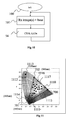
step 52, themicroprocessor 40 determines a new colour base dependent on the image received and called a secondary colour base. This secondary colour base corresponds to atriangle 71 covering anarea 72 of a gamut comprising each of the pixels of the image and represented, by way of illustration, in Figure 7. - The
area 72 is inscribed in thetriangle 71, the corners of which are thepoints area 72 can be expressed. Preferably, all the pixels of thearea 72 can be expressed with positive coefficients in the secondary colour base (negative coefficients corresponding to points outside the triangle concerned). - The saturated red, green and blue colours are respectively represented by
points triangle 70 having for corners thepoints 700 to 702 covers the range of colours that can be obtained. Thepoint 710 corresponds to a mixture of red and green and is therefore located on the segment linking thepoints points points - Preferably, during the
step 52, thecontroller 210 searches for thetriangle 71 of maximum compactness (the compactness being calculated by obtaining the ratio between the area of thetriangle 71 and its perimeter squared). - Figure 8 illustrates the secondary colour base corresponding to a
frame 62 received by the controller during thestep 51 and determined during thestep 52. This new base corresponds to atriangle 81 covering anarea 82 of a gamut comprising each of the pixels of theframe 82. - The
area 82 is inscribed in thetriangle 81 having for corners thepoints area 82 can be expressed. - The
points points 700 to 702 associated with the primary colours. Thepoint 811 corresponds to a mixture of blue and red. By using an illumination from LEDs, the mixture of two or three primary colours can be adapted. It is, in practice, possible to obtain all the colours resulting from the sum of a certain quantity of blue, green and/or red by switching on the corresponding LEDs for a suitable time and/or intensity. There is thus a great deal of flexibility in the choice of the secondary colour base. - According to a first variant of searching for the
triangles initialization step 50, a number of triangles (represented for example by the coordinates of their corners or the equations defining their sides) included in thetriangle 70 are determined and stored, with, preferably, their compactness and the data concerning the percentage of primary colour associated with each of its corners. During thestep 50, themicrocontroller 210 checks for all the predetermined triangles that each pixel of the image received (the pixels being represented symbolically by black dots) is in the predetermined triangle concerned, then selects the triangle that has the greater compactness. It is always possible to find such a triangle, thetriangles - According to a second variant of searching for the triangles 71 (respectively 81), during the
step 52, starting from the triangle 72 (respectively 82), the microcontroller drags along the sides of the triangle, progressively or by dichotomy, each corner to determine a triangle and checks whether all the pixels of the image are contained in the duly determined triangle. If all the pixels of the image are effectively contained in the triangle, the process is repeated by trying to reduce the compactness or the size of the triangle, otherwise it is stopped (if the triangles are determined by progressively dragging the sides) or repeated by increasing the compactness of the triangle (if the triangles are determined by dichotomic dragging of the sides). Generally, the repetitions stop after a predetermined maximum number, and/or when an appropriate triangle compactness is less than a predetermined compactness and/or when the compactness difference between an appropriate triangle and a triangle that is inappropriate is less than a predetermined value. - According to different variants for determining the
triangle 71, the corners of thetriangle 71 are chosen on the three sides of the triangle 72 (the corners of thetriangle 71 being on three separate sides) or on two separate sides of thetriangle 72. According to other variants, the corners of thetriangle 71 are chosen outside the sides of the triangle 72 (for example, by distorting thetriangle 72 homothetically, or by retaining one or two corners of thetriangle 71 on one or two sides of thetriangle 72, the third corner of thetriangle 71 being placed inside the triangle 72). - According to a variant for selecting the
triangles step 52, only the triangles that do not cover a predetermined percentage of pixels of the image (typically at least 90%, for example 90%, 95%, 99%, 99.9%) are rejected. This variant allows certain isolated pixels not to be considered and therefore provides a saving in light power. - When the triangle 71 ( respectively 81) is determined, during a
step 53, themicrocontroller 210 encodes each of the pixels according to the duly determined triangle. - If, according to a variant of the invention, all the pixels are not in the triangle 71 (respectively 81), these pixels are associated with a nearby pixel corresponding to an approximate colour. This pixel is, for example, located on one of the sides of the triangle 71 (respectively 81), preferably as near as possible to or on the straight line linking the pixel concerned to the centre of the triangle 72 (respectively 82).
- According to a variant of the invention, in order to simplify the search for a triangle encompassing all the pixels of a frame and/or the check that all the pixels of this frame belong to a determined triangle, the controller first determines a convex envelope linking the peripheral pixels. This envelope comprises all the pixels by definition and it is sufficient to search for a triangle encompassing the peripheral pixels and/or check that the peripheral pixels are contained in the determined triangle for the triangle search and/or the check to be valid for all the pixels of the image.
- Then, during a
step 54, the controller determines and transmitscontrol data 423 to theLED driver 213 according to the secondary colour base. Thecontrol data 423 specifies the on time and/or intensity of the LEDs for each colour in each frame. During this step, the controller also transmits thedata 422 representative of the image encoded according to the secondary colour base to theimager driver 214 which in turn transmits it to theimager 205. - Following the
step 54, thestep 50 is repeated. - Figure 6 gives an example of dynamic illumination management for two successive images corresponding to two
frames LED driver 213 controlling the on time of each LED according to the secondary colour base. Each of theframes - Each of the
lines 600 to 604 illustrates the management of the colours over time, and more specifically: - the
line 600 illustrates the average perception of a colour in each of thetime slots 610 to 612 and 620 to 622; - the
lines 602 to 604 show the control of the LEDs respectively coloured red, green and blue (or the perception of these LEDs that are either on or off). - the
line 601 indicates the result of the instantaneous summing of the illumination beams corresponding to the red, green and blue LEDs. - For each frame, the three corresponding time slots are mostly respectively red, green and blue, but can include an unsaturated part according to the calculation of the
step 51, as illustrated on theline 601. - As an illustration, Figure 6 corresponds to a calculation of the
step 51 having determined that thearea 72 of the pixels corresponding to theframe 61 is inscribed in a triangle having for corners thepoints - red + 25% green;
- green + 25% blue;
- blue + 33% green.
- Thus, during the
first time slot 610, the or each red LED will be on throughout the time slot and the or each green LED will be on for 25% of the time which gives the average as represented on theline 600. - Similarly, during the second time slot 611 (respectively third time slot 612), the or each green (respectively blue) LED will be on throughout the duration of the time slot and the or each blue (respectively green) LED will be on for 25% (respectively 33%) of the time.
- For the
following time slot 62, as an illustration, thestep 51 has determined that thearea 92 of the pixels is inscribed in a triangle having for corners thepoints - red + 5% blue + 25% green;
- green + 33% blue + 2% red;
- blue + 25% red.
- Thus, during the time slot 6 20, the or each red LED will be on throughout the duration of the time slot and the blue and green LEDs will be on respectively 5% and 25% of the time which gives the average as represented on the
line 600. - Similarly, during the time slot 621 (respectively 622), the or each green (respectively blue) LED will be on throughout the duration of the time slot, the or each blue (respectively red) LED will be on for 33% (respectively 25%) of the time and the or each red LED will be on for 2% of the time (respectively the or each green LED will be off).
- According to an embodiment variant of the invention, to partially introduce a red, green or blue colour during a determined time slot, the or each corresponding LED is switched on throughout the time slot. Thus, according to a method of modulating the light intensity of the LEDs, the
driver 213 controls the intensity of the supply current to the LEDs to vary the transmitted light power. Figure 9 represents acurve 92 giving the relative light intensity 91 (Y axis) according to the controlling electrical intensity 90 (expressed in mA on the X axis). Thedriver 213 thus receives, from thecontroller 210, the relative light intensity for each LED colour and for the three time slots of a frame (for example, for the time slot 610: 1 for red, 0.33 for green and 0 for blue). Then, thedriver 213 converts them into a light intensity control according to time and the or each LED concerned (for example via a conversion table and/or by calculation (in particular in the roughly linear part of thecurve 92 corresponding to intensity values 90 less than 5 mA according to the example illustrated in Figure 9)). - According to this variant, if the
LED array 200 includes several LEDs of the same colour, according to a method of partially switching on the LEDs of one and the same colour, thedriver 213 can also switch on only some of the LEDs of this colour (for example, if thearray 200 includes 30 green LEDs, to obtain 33% green in thetime slot 610, thedriver 213 can request the switching on of a maximum of 10 green LEDs, the 20 other green LEDs remaining off). - According to this variant, if the
LED array 200 includes a number of LEDs of one and the same colour, thedriver 213 can also mix the two methods of modulating the light intensity of a colour and of partially switching on the LEDs of this colour (for example, if thearray 200 includes 30 green LEDs, to obtain 33% green in thetime slot 610, thedriver 213 can request the switching on with 50% of the maximum intensity of 20 green LEDs, the 10 other green LEDs remaining off). - Thus, according to the invention, the duration of the light pulses transmitted by the LEDs and/or their light intensity is adjusted frame by frame according to the secondary colour base. In other words, the time and/or the energy of the coloured LEDs can vary from one image to the next and different colour LEDs can be switched on at the same time. In this way, the illumination source is very flexible and is optimized to obtain a better quality projected image and/or reduce the overall energy consumption (the LEDs being on for a shorter time and/or being powered with a lesser electrical intensity).
- According to an embodiment variant of the invention illustrated by Figure 10, the images received by the controller are already encoded according to a secondary colour base. Data representative of the secondary colour base is also received by the controller. According to this variant, the images are, in effect, encoded according to the secondary colour base (according to any one of the methods described previously), for example, after the encoding operation, or during the operation for storing on any medium, or even on sending the images to the controller. Thus, the means of determining the secondary colour base can advantageou sly be transferred to a remote device, the duly encoded images being able to be used by a number of image display systems (in particular by projectors including an illumination source with or without LEDs). The means of determining the secondary colour base can also be transferred to any dedicated equipment inside the projector (for example, in the image reception means).
- Thus, according to this variant, after an
initialization phase 100, during astep 101, the controller waits for then receives the data representative of an image in the secondary colour base dependent on the image received or a set of several images. It also receives the data representative of the secondary colour base. The data representative of the base is, for example, a code specific to several possible bases pre-stored in the memory of the controller, possibly downloaded in advance, or the coordinates of this secondary colour base in a primary colour base. - Then, the controller performs a
step 54 for transmitting the data to theLED driver 213 and the image encoded according to the secondary colour base to theimager driver 214 which in turn transmits it to theimager 205. This step is similar to thestep 54 illustrated by Figure 5, so it carries the same reference and will not be described in any further detail. - Then, the
step 101 is repeated. - Naturally, the invention is not limited to the embodiments described above.
- In particular, the invention is compatible with any type of projector (in particular front or overhead projectors) comprising at least one imager lit by a sequentially coloured beam from coloured LEDs.
- Those skilled in the art can also adapt the invention to any type of mechanical and/or optical structure using the coloured LEDs. They can, in particular, vary the number of LEDs of each colour (for example from one LED of each colour (high power LED) to more than ten LEDs of each colour). The positioning of the LEDs in the illumination system can vary: they can be in a flat monolithic array as illustrated by Figure 3 or be associated with a number of monochrome LED arrays (for example, three respectively green, blue and red LED arrays) on one and the same plane or not (the structure possibly comprising dichroic return mirrors, enabling beams of different colours to be combined into a single beam illuminating the or each imager) or even remote from the imager, the coloured beams being transmitted to the or each imager via appropriate optical systems (for example, via optical fibres).
- The invention is also compatible with illumination systems comprising LEDs of different colours, for example cyan or yellow, not necessarily red, green or blue, or even comprising green, blue or red LEDs of different wavelengths (for example green LEDs at 520 nm and 560 nm, and/or blue LEDs at 440 nm a nd 460 nm, and/or red LEDs at 600 nm and 630 nm). Thus, the gamut can be extended. According to this variant, the determination of the secondary colour base and the encoding of the images in this base takes into account the characteristics of the LEDs (implemented when the means of determining the secondary colour base are associated with the illumination means or possible when the means of determining the secondary colour base and the encoding means are remote, in the case of images encoded outside the LED control means), not necessarily red, green or blue respectively associated with a single wavelength since the range of possible colours is greater (thus, for example, a triangle is defined which comprises a predetermined percentage of pixels of an image in the polygon representative of the LEDs (colours and associated power) forming the illumination means). According to this variant, all the colours resulting from the sum of a certain quantity and/or type of blue, green and/or red are obtained by switching on (via the LED driver) the selected LEDs for an appropriate time and/or appropriate intensity.
- As an illustration, Figure 11 presents a gamut according to this variant of the invention, associated with a system comprising
green LEDs blue LEDs red LEDs 700 at a single wavelength, for example, the primary colour base is associated with thegreen LEDs 702 at 560 nm, theblue LEDs 701 at 440 nm and thered LEDs 700. Then, according to the invention, for a first given image or a first set of relatively saturated images, the secondary colour base comprises, for example, the green 1113 at 520 nm, the blue 701 at 440 nm and the red 700 that corresponds to a triangle having for corners thepoints pixels 1117 illustrated diagrammatically), the secondary colour base comprises, for example: - a mixture of green 1113 at 520 nm and blue 1114 at 460 nm (
point 1112 corresponding to an unsaturated colour obtained by selecting theLEDs - a mixture of green 702 at 560 nm and red 700 (
point 1110 corresponding to an unsaturated colour obtained by selecting theLEDs - a mixture of green 702 at 560 nm, blue 701 at 440 nm and red 700 (
point 1114 corresponding to an unsaturated colour obtained by selecting theLEDs - Moreover, the invention is not limited to the case where the secondary colour base comprises only three colours, but can be extended to secondary colour bases comprising more than three colours (for example, four, five, six, etc.). Thus, as an illustration, the secondary colour base can comprise p colours (p being, for example, three, four, five, six, etc.). According to this variant, to determine the secondary colour base, instead of defining a triangle associated with the secondary colour base, a polygon with p corners is defined, each of the corners representing an LED colour or a mixture of LED colours, the polygon encompassing all or some (typically at least 90%) of the pixels of an image or a set of images. According to the invention, the number of colours in the secondary colour base can also vary dynamically from one image to the next.
- According to a variant of the invention implementing LEDs corresponding to more than three distinct colours, the step for determining the secondary colour base comprises a step for selecting a polygon, the corners of which correspond to an LED colour; according to this variant, the selection step comprises a step for checking a predetermined condition. According to this condition, each polygon that is a candidate for selection comprises all the pixels (or, according to a variant, at least a predetermined quantity, for example, 90% of pixels). The selection step is completed by the choice of a polygon, the corners of which specify the secondary colour base, out of the polygon or polygons that satisfy the predetermined condition by, where appropriate, taking into account their compactness (a compactness being preferred) and/or, if appropriate, the percentage of pixels covered by the polygon (a high percentage being preferred).
- The invention is by no means limited to the case where the LED control system is as described previously, but can, by contrast, be extended to any system performing an analysis of one or more images to determine an area of the colour gamut comprising a predetermined percentage of pixels of the or each image concerned and capable of being covered by the LEDs. In particular, when the content of a number of consecutive images is relatively similar, the corresponding secondary colour base can, advantageously, be determined, according to the invention, over the set of these images or over a limited number of these images, even just one of these images. In particular, the secondary colour base can advantageously be determined at regular intervals (for example, every second, or every n images (n being, for example, 2, 5, 12, 24, etc.) or on an abrupt variation of the content of an image (identified, for example, by performing a correlation between two consecutive images of a stream of frames received) or even in a way synchronized on intra-encoded images (in an MPEG2 or MPEG4 stream, for example) (the determination of the secondary colour base being done from intra-encoded images, the predictive or bipredictive images using the same secondary colour base as that associated with the intra image corresponding to them).
- According to a variant of the invention, the secondary colour base is determined for certain images (for example as indicated above) from the content of these images, and the secondary colour base is determined for the subsequent images by simply checking that a predetermined percentage of pixels in these images can be encoded with positive coordinates in the secondary colour base determined previously. If they can, the subsequent images are encoded in the secondary colour base determined previously. If not, the subsequent images are either encoded with this secondary colour base, certain pixels capable of being encoded approximately, or a new colour base is determined from the first subsequent image that does not satisfy the minimum percentage of pixels condition that can be encoded with the secondary colour base determined previously.
- The invention is also compatible with a secondary colour base that comprises more than three elements and, in particular, that comprises white (obtained, for example, with a white light or by superimposing several lightings each associated with a primary colour).
- The invention is also compatible with any type of imager ( or micro-display); thus, it can be applied not only to projectors with transmissive LCD (Liquid Crystal Display), but also to projectors with DMD (Digital Micromirror Device produced by Texas Instruments ®) type imagers or LCOS (Liquid Crystal On Silicon) type imagers (those skilled in the art incorporating the appropriate optical elements (polarisers, lenses, mirrors, etc.) between the illumination source and the imager).
Claims (14)
- Method of illuminating an imager (205) for projecting (2) images, implementing light -emitting diodes (200) of different colours, said diodes being designed to provide a beam (202) illuminating said imager,
characterized in that, for a set of at least one image, said method comprises:- a step for receiving (51, 101) each image of said set;- a step for determining (52, 101) a colour base dependent on said set of at least one image, called a secondary colour base;- a step (54) for dynamically controlling said diodes according to said secondary colour base. - Method according to Claim 1, characterized in that said secondary colour base comprises at least one secondary colour corresponding to a mixture of two primary colours.
- Method according to either Claim 1 or Claim 2, characterized in that said secondary colour base comprises three colours.
- Method according to any one of Claims 1 to 3, characterized in that said step for dynamically controlling said diodes comprises a step for controlling the on time of said diodes according to said secondary colour base.
- Method according to any one of Claims 1 to 4, characterized in that said step for dynamically controlling said diodes comprises a step for controlling the light intensity of said diodes according to said secondary colour base.
- Method according to any one of Claims 1 to 5, characterized in that said step for dynamically controlling said diodes comprises a step for selecting said diodes according to said secondary colour base.
- Method according to any one of Claims 1 to 6, characterized in that, in said step for receiving (51) said set of at least one image, each image is received in a colour base, called a primary colour base, said primary colour base being distinct from said secondary colour base, said step for determining (52) a colour base comprising a step for converting each image from said primary colour base to said secondary colour base.
- Method according to Claim 7, characterized in that said step for determining a colour base comprises a step for calculating an area encompassing at least 90% of the pixels of the images of said set, said colour base being determined according to said area.
- Method according to Claim 8, characterized in that said area encompasses 100% of the pixels of the images of said set.
- Method according to either of Claims 8 and 9, characterized in that said area forms a polygon.
- Method according to any one of Claims 1 to 6, characterized in that, in said step for receiving (101) said set of at least one image, each image is received in said secondary colour base, said step for determining (101) a colour base comprising a step for receiving data representative of said secondary colour base.
- Method according to any one of Claims 1 to 11, characterized in that said set comprises a single image.
- Illumination system (20) intended to light an imager (205) for projecting (2) images and comprising light-emitting diodes (200) of different colours, said diodes being designed to provide a beam illuminating said imager,
said system being characterized in that, for a set of at least one image, said system comprises:- means of receiving (210) each image of said set;- means of determining (210) a colour base dependent on said set of at least one image, called a secondary colour base;- means of dynamically controlling (210, 213) said diodes according to said secondary colour base. - Image projector (2) comprising,- at least one projection lens (22);- at least one imager (205);- at least one illumination system (20) according to Claim 13 intended to light said imager and comprising light-emitting diodes (200) of different colours, said diodes being designed to provide a beam (202) illuminating said imager,said system comprising:- means of receiving (210) each image of said set;- means of determining (210) a colour base dependent on said set of at least one image, called a secondary colour base;- means of dynamically controlling (210, 213) said diodes according to said secondary colour base.
Applications Claiming Priority (1)
| Application Number | Priority Date | Filing Date | Title |
|---|---|---|---|
| FR0506474A FR2887640B1 (en) | 2005-06-24 | 2005-06-24 | METHOD FOR ILLUMINATING A PROJECTOR IMAGER, SYSTEM AND PROJECTOR THEREFOR |
Publications (1)
| Publication Number | Publication Date |
|---|---|
| EP1737245A1 true EP1737245A1 (en) | 2006-12-27 |
Family
ID=35478928
Family Applications (1)
| Application Number | Title | Priority Date | Filing Date |
|---|---|---|---|
| EP06115180A Withdrawn EP1737245A1 (en) | 2005-06-24 | 2006-06-08 | Method of illuminating a projecting imager, corresponding system and projector |
Country Status (6)
| Country | Link |
|---|---|
| US (1) | US7938546B2 (en) |
| EP (1) | EP1737245A1 (en) |
| JP (1) | JP5189742B2 (en) |
| KR (1) | KR101222670B1 (en) |
| CN (1) | CN1885154B (en) |
| FR (1) | FR2887640B1 (en) |
Cited By (1)
| Publication number | Priority date | Publication date | Assignee | Title |
|---|---|---|---|---|
| WO2008035259A1 (en) * | 2006-09-20 | 2008-03-27 | Koninklijke Philips Electronics N.V. | Dynamic gamut control |
Families Citing this family (6)
| Publication number | Priority date | Publication date | Assignee | Title |
|---|---|---|---|---|
| US8212859B2 (en) * | 2006-10-13 | 2012-07-03 | Apple Inc. | Peripheral treatment for head-mounted displays |
| EP2250818A1 (en) * | 2008-02-08 | 2010-11-17 | Koninklijke Philips Electronics N.V. | Light module device |
| CN101737701B (en) * | 2010-01-07 | 2013-03-20 | 苏州佳世达光电有限公司 | Light-emitting diode lighting system and control method thereof, and projector |
| JP5750572B2 (en) * | 2010-03-30 | 2015-07-22 | パナソニックIpマネジメント株式会社 | Projection-type image display device |
| FR2993675B1 (en) * | 2012-07-18 | 2015-05-22 | Valeo Etudes Electroniques | DEVICE AND METHOD FOR TRANSMITTING A LIGHT BEAM FOR FORMING AN IMAGE, PROJECTION SYSTEM AND DISPLAY USING THE SAME |
| JP6064455B2 (en) | 2012-09-04 | 2017-01-25 | カシオ計算機株式会社 | Projection apparatus, projection method, and program |
Citations (3)
| Publication number | Priority date | Publication date | Assignee | Title |
|---|---|---|---|---|
| US6224216B1 (en) * | 2000-02-18 | 2001-05-01 | Infocus Corporation | System and method employing LED light sources for a projection display |
| US20040008288A1 (en) * | 2002-01-31 | 2004-01-15 | Pate Michael A. | Adaptive image display |
| US20050030400A1 (en) * | 2000-06-26 | 2005-02-10 | Canon Kabushiki Kaisha | Image display device |
Family Cites Families (36)
| Publication number | Priority date | Publication date | Assignee | Title |
|---|---|---|---|---|
| EP0676115B1 (en) * | 1993-10-21 | 2000-06-07 | Koninklijke Philips Electronics N.V. | Image projection device and lamp control system for use therein |
| JP3673317B2 (en) * | 1996-04-09 | 2005-07-20 | シチズン時計株式会社 | Display device |
| US6281949B1 (en) * | 1997-03-24 | 2001-08-28 | Sony Corporation | Apparatus for displaying a picture which involves spatially modulating a light beam |
| JP3585097B2 (en) * | 1998-06-04 | 2004-11-04 | セイコーエプソン株式会社 | Light source device, optical device and liquid crystal display device |
| CN100390599C (en) * | 1998-06-05 | 2008-05-28 | 精工爱普生株式会社 | Light source and display device |
| US6359662B1 (en) * | 1999-11-05 | 2002-03-19 | Agilent Technologies, Inc. | Method and system for compensating for defects in a multi-light valve display system |
| JP2001188513A (en) * | 1999-12-28 | 2001-07-10 | Matsushita Electric Ind Co Ltd | Display device |
| WO2001069584A1 (en) * | 2000-03-14 | 2001-09-20 | Mitsubishi Denki Kabushiki Kaisha | Image display and image displaying method |
| KR100725426B1 (en) * | 2000-11-23 | 2007-06-07 | 엘지.필립스 엘시디 주식회사 | Time division type liquid crystal display device and color image display method thereof |
| JP3450842B2 (en) * | 2000-11-30 | 2003-09-29 | キヤノン株式会社 | Color liquid crystal display |
| JP2002244626A (en) * | 2001-02-22 | 2002-08-30 | Sharp Corp | Color sequential display |
| TW571119B (en) * | 2001-12-20 | 2004-01-11 | Delta Electronics Inc | Image projection device with integrated semiconductor light emitting element light source |
| US7391475B2 (en) * | 2002-01-31 | 2008-06-24 | Hewlett-Packard Development Company, L.P. | Display image generation with differential illumination |
| US7283181B2 (en) * | 2002-01-31 | 2007-10-16 | Hewlett-Packard Development Company, L.P. | Selectable color adjustment for image display |
| JP3878030B2 (en) * | 2002-02-22 | 2007-02-07 | 富士通株式会社 | Image display device and image display method |
| JP4055610B2 (en) * | 2002-03-22 | 2008-03-05 | セイコーエプソン株式会社 | Image display device and projector |
| JP2004012876A (en) * | 2002-06-07 | 2004-01-15 | Toshiba Corp | Projection display device |
| JP2004111357A (en) * | 2002-07-09 | 2004-04-08 | Topcon Corp | Light source device |
| JP4027747B2 (en) * | 2002-08-07 | 2007-12-26 | オリンパス株式会社 | Illumination device and projection display device |
| JP4046585B2 (en) * | 2002-10-01 | 2008-02-13 | オリンパス株式会社 | LIGHTING DEVICE AND PROJECTION DISPLAY DEVICE USING THE LIGHTING DEVICE |
| US6769772B2 (en) * | 2002-10-11 | 2004-08-03 | Eastman Kodak Company | Six color display apparatus having increased color gamut |
| JP2004184852A (en) * | 2002-12-05 | 2004-07-02 | Olympus Corp | Display device, light source device, and lighting device |
| JP2004311635A (en) * | 2003-04-04 | 2004-11-04 | Olympus Corp | DRIVE DEVICE, LIGHTING DEVICE USING THE SAME, AND DISPLAY DEVICE USING THE LIGHTING DEVICE |
| JP2004335992A (en) * | 2003-04-18 | 2004-11-25 | Victor Co Of Japan Ltd | Light source unit and projection display device applied with the light source unit |
| JP3858850B2 (en) * | 2003-05-06 | 2006-12-20 | セイコーエプソン株式会社 | Display device, display method, and projector |
| FR2854698A1 (en) * | 2003-05-09 | 2004-11-12 | Thomson Licensing Sa | Sequential illumination system for spatial light modulator, has colored wheel with sub-set of composed color segments having segments transmitting in red and green, green and blue, and red and blue wavelength fields, respectively |
| US20050052376A1 (en) * | 2003-08-19 | 2005-03-10 | Shivji Shiraz M. | Method and apparatus for light emitting devices based display |
| JP2005107211A (en) * | 2003-09-30 | 2005-04-21 | Olympus Corp | Image projector |
| JP2005134482A (en) * | 2003-10-28 | 2005-05-26 | Olympus Corp | Image projector |
| US7258450B2 (en) * | 2003-12-04 | 2007-08-21 | Sharp Kabushiki Kaisha | Projector optical system configuration, optical module, and projector, and also electronic equipment, vehicle, projection system, and showcase utilizing such projector |
| JP2005189653A (en) * | 2003-12-26 | 2005-07-14 | Olympus Corp | Image projector |
| JP4665402B2 (en) * | 2004-02-04 | 2011-04-06 | セイコーエプソン株式会社 | Projection type display device, control method for projection type display device, and control program for projection type display device |
| US7083284B2 (en) * | 2004-04-30 | 2006-08-01 | Infocus Corporation | Method and apparatus for sequencing light emitting devices in projection systems |
| JP4328738B2 (en) * | 2004-05-06 | 2009-09-09 | キヤノン株式会社 | LCD color display |
| JP4368780B2 (en) * | 2004-11-05 | 2009-11-18 | 三菱電機株式会社 | Image display device |
| US7422330B2 (en) * | 2005-03-30 | 2008-09-09 | 3M Innovative Properties Company | Illumination system and projection system using same |
-
2005
- 2005-06-24 FR FR0506474A patent/FR2887640B1/en not_active Expired - Fee Related
-
2006
- 2006-06-08 EP EP06115180A patent/EP1737245A1/en not_active Withdrawn
- 2006-06-12 KR KR1020060052378A patent/KR101222670B1/en not_active Expired - Fee Related
- 2006-06-22 US US11/472,629 patent/US7938546B2/en not_active Expired - Fee Related
- 2006-06-23 CN CN2006100932730A patent/CN1885154B/en not_active Expired - Fee Related
- 2006-06-23 JP JP2006174100A patent/JP5189742B2/en not_active Expired - Fee Related
Patent Citations (3)
| Publication number | Priority date | Publication date | Assignee | Title |
|---|---|---|---|---|
| US6224216B1 (en) * | 2000-02-18 | 2001-05-01 | Infocus Corporation | System and method employing LED light sources for a projection display |
| US20050030400A1 (en) * | 2000-06-26 | 2005-02-10 | Canon Kabushiki Kaisha | Image display device |
| US20040008288A1 (en) * | 2002-01-31 | 2004-01-15 | Pate Michael A. | Adaptive image display |
Cited By (2)
| Publication number | Priority date | Publication date | Assignee | Title |
|---|---|---|---|---|
| WO2008035259A1 (en) * | 2006-09-20 | 2008-03-27 | Koninklijke Philips Electronics N.V. | Dynamic gamut control |
| US8390643B2 (en) | 2006-09-20 | 2013-03-05 | Koninklijke Philips Electronics N.V. | Dynamic gamut control |
Also Published As
| Publication number | Publication date |
|---|---|
| FR2887640B1 (en) | 2008-10-03 |
| KR20060135501A (en) | 2006-12-29 |
| FR2887640A1 (en) | 2006-12-29 |
| KR101222670B1 (en) | 2013-01-16 |
| JP5189742B2 (en) | 2013-04-24 |
| US20070052932A1 (en) | 2007-03-08 |
| CN1885154A (en) | 2006-12-27 |
| JP2007004180A (en) | 2007-01-11 |
| CN1885154B (en) | 2010-05-12 |
| US7938546B2 (en) | 2011-05-10 |
Similar Documents
| Publication | Publication Date | Title |
|---|---|---|
| CN106154711B (en) | A kind of optical projection system and its colour gamut control method | |
| EP3196696B1 (en) | Laser light source and laser display system | |
| US8665179B2 (en) | Projection apparatus, projection method, and storage medium having program stored thereon | |
| KR100936836B1 (en) | Computer-readable recording media recording the projector, projector system, and program | |
| US8711290B2 (en) | Projection-type video-image display apparatus | |
| US9064443B2 (en) | Projection apparatus, projection method, and storage medium storing program, for reducing energy consumption by shortening color mixing period | |
| US20080239248A1 (en) | Display illumination apparatus | |
| US20130094001A1 (en) | Projector, projection control method, and storage medium storing program | |
| JP2009216857A (en) | Projector, image display system, and image correction method | |
| US7926950B2 (en) | Laser image display device and color image display method utilizing control of the power of plural laser beams to display a pixel | |
| WO2016124096A1 (en) | Projection system and control method therefor | |
| CN119422102A (en) | Projection device and method for driving light source thereof | |
| US20190191132A1 (en) | Projection video display apparatus | |
| US7938546B2 (en) | Method of illuminating a projecting imager, corresponding system and projector | |
| CN106462041B (en) | Image display device and image generation method | |
| US20140292836A1 (en) | Projection-type image display device, image projection control device, and image projection control method | |
| CN113970873A (en) | Optical machine illumination system | |
| CN116828162A (en) | Display system and display control method | |
| JP5167095B2 (en) | Illumination device and projection display device | |
| US20250088613A1 (en) | Projection apparatus and display method thereof, storage medium | |
| JP2009080277A (en) | Projection image display device | |
| JP4539099B2 (en) | Projection type display device, control method for projection type display device, and image output device | |
| JP2008026682A (en) | Color sequential image display method and color sequential image display apparatus | |
| KR20190136875A (en) | Optical system and image projection device including the same | |
| JP2010177979A (en) | Multi-vision system |
Legal Events
| Date | Code | Title | Description |
|---|---|---|---|
| PUAI | Public reference made under article 153(3) epc to a published international application that has entered the european phase |
Free format text: ORIGINAL CODE: 0009012 |
|
| AK | Designated contracting states |
Kind code of ref document: A1 Designated state(s): AT BE BG CH CY CZ DE DK EE ES FI FR GB GR HU IE IS IT LI LT LU LV MC NL PL PT RO SE SI SK TR |
|
| AX | Request for extension of the european patent |
Extension state: AL BA HR MK YU |
|
| 17P | Request for examination filed |
Effective date: 20070626 |
|
| AKX | Designation fees paid |
Designated state(s): DE FR GB |
|
| 17Q | First examination report despatched |
Effective date: 20070921 |
|
| RAP1 | Party data changed (applicant data changed or rights of an application transferred) |
Owner name: THOMSON LICENSING |
|
| STAA | Information on the status of an ep patent application or granted ep patent |
Free format text: STATUS: EXAMINATION IS IN PROGRESS |
|
| STAA | Information on the status of an ep patent application or granted ep patent |
Free format text: STATUS: THE APPLICATION IS DEEMED TO BE WITHDRAWN |
|
| 18D | Application deemed to be withdrawn |
Effective date: 20170103 |