EP1737134A2 - Adaptive pulse shaping filter based on interference detection - Google Patents
Adaptive pulse shaping filter based on interference detection Download PDFInfo
- Publication number
- EP1737134A2 EP1737134A2 EP06253187A EP06253187A EP1737134A2 EP 1737134 A2 EP1737134 A2 EP 1737134A2 EP 06253187 A EP06253187 A EP 06253187A EP 06253187 A EP06253187 A EP 06253187A EP 1737134 A2 EP1737134 A2 EP 1737134A2
- Authority
- EP
- European Patent Office
- Prior art keywords
- filter
- signal
- frequency
- communication system
- shaping filter
- Prior art date
- Legal status (The legal status is an assumption and is not a legal conclusion. Google has not performed a legal analysis and makes no representation as to the accuracy of the status listed.)
- Granted
Links
Images








Classifications
-
- H—ELECTRICITY
- H04—ELECTRIC COMMUNICATION TECHNIQUE
- H04L—TRANSMISSION OF DIGITAL INFORMATION, e.g. TELEGRAPHIC COMMUNICATION
- H04L25/00—Baseband systems
- H04L25/02—Details ; arrangements for supplying electrical power along data transmission lines
- H04L25/03—Shaping networks in transmitter or receiver, e.g. adaptive shaping networks
- H04L25/03828—Arrangements for spectral shaping; Arrangements for providing signals with specified spectral properties
- H04L25/03834—Arrangements for spectral shaping; Arrangements for providing signals with specified spectral properties using pulse shaping
-
- H—ELECTRICITY
- H04—ELECTRIC COMMUNICATION TECHNIQUE
- H04B—TRANSMISSION
- H04B1/00—Details of transmission systems, not covered by a single one of groups H04B3/00 - H04B13/00; Details of transmission systems not characterised by the medium used for transmission
- H04B1/06—Receivers
- H04B1/10—Means associated with receiver for limiting or suppressing noise or interference
- H04B1/1027—Means associated with receiver for limiting or suppressing noise or interference assessing signal quality or detecting noise/interference for the received signal
- H04B1/1036—Means associated with receiver for limiting or suppressing noise or interference assessing signal quality or detecting noise/interference for the received signal with automatic suppression of narrow band noise or interference, e.g. by using tuneable notch filters
-
- H—ELECTRICITY
- H04—ELECTRIC COMMUNICATION TECHNIQUE
- H04B—TRANSMISSION
- H04B1/00—Details of transmission systems, not covered by a single one of groups H04B3/00 - H04B13/00; Details of transmission systems not characterised by the medium used for transmission
- H04B1/06—Receivers
- H04B1/10—Means associated with receiver for limiting or suppressing noise or interference
- H04B1/109—Means associated with receiver for limiting or suppressing noise or interference by improving strong signal performance of the receiver when strong unwanted signals are present at the receiver input
-
- H—ELECTRICITY
- H04—ELECTRIC COMMUNICATION TECHNIQUE
- H04J—MULTIPLEX COMMUNICATION
- H04J11/00—Orthogonal multiplex systems, e.g. using WALSH codes
- H04J11/0023—Interference mitigation or co-ordination
- H04J11/0026—Interference mitigation or co-ordination of multi-user interference
- H04J11/003—Interference mitigation or co-ordination of multi-user interference at the transmitter
-
- H—ELECTRICITY
- H04—ELECTRIC COMMUNICATION TECHNIQUE
- H04J—MULTIPLEX COMMUNICATION
- H04J11/00—Orthogonal multiplex systems, e.g. using WALSH codes
- H04J11/0023—Interference mitigation or co-ordination
- H04J11/005—Interference mitigation or co-ordination of intercell interference
-
- H—ELECTRICITY
- H04—ELECTRIC COMMUNICATION TECHNIQUE
- H04L—TRANSMISSION OF DIGITAL INFORMATION, e.g. TELEGRAPHIC COMMUNICATION
- H04L25/00—Baseband systems
- H04L25/02—Details ; arrangements for supplying electrical power along data transmission lines
- H04L25/03—Shaping networks in transmitter or receiver, e.g. adaptive shaping networks
- H04L25/03006—Arrangements for removing intersymbol interference
- H04L25/03012—Arrangements for removing intersymbol interference operating in the time domain
- H04L25/03019—Arrangements for removing intersymbol interference operating in the time domain adaptive, i.e. capable of adjustment during data reception
- H04L25/03038—Arrangements for removing intersymbol interference operating in the time domain adaptive, i.e. capable of adjustment during data reception with a non-recursive structure
- H04L25/03044—Arrangements for removing intersymbol interference operating in the time domain adaptive, i.e. capable of adjustment during data reception with a non-recursive structure using fractionally spaced delay lines or combinations of fractionally integrally spaced taps
-
- H—ELECTRICITY
- H04—ELECTRIC COMMUNICATION TECHNIQUE
- H04L—TRANSMISSION OF DIGITAL INFORMATION, e.g. TELEGRAPHIC COMMUNICATION
- H04L25/00—Baseband systems
- H04L25/02—Details ; arrangements for supplying electrical power along data transmission lines
- H04L25/03—Shaping networks in transmitter or receiver, e.g. adaptive shaping networks
- H04L25/03828—Arrangements for spectral shaping; Arrangements for providing signals with specified spectral properties
- H04L25/03834—Arrangements for spectral shaping; Arrangements for providing signals with specified spectral properties using pulse shaping
- H04L25/03853—Shaping by digital methods other than look up tables or up/down converters
-
- H—ELECTRICITY
- H04—ELECTRIC COMMUNICATION TECHNIQUE
- H04L—TRANSMISSION OF DIGITAL INFORMATION, e.g. TELEGRAPHIC COMMUNICATION
- H04L27/00—Modulated-carrier systems
- H04L27/26—Systems using multi-frequency codes
- H04L27/2601—Multicarrier modulation systems
- H04L27/2626—Arrangements specific to the transmitter only
- H04L27/2646—Arrangements specific to the transmitter only using feedback from receiver for adjusting OFDM transmission parameters, e.g. transmission timing or guard interval length
-
- H—ELECTRICITY
- H04—ELECTRIC COMMUNICATION TECHNIQUE
- H04L—TRANSMISSION OF DIGITAL INFORMATION, e.g. TELEGRAPHIC COMMUNICATION
- H04L25/00—Baseband systems
- H04L25/02—Details ; arrangements for supplying electrical power along data transmission lines
- H04L25/03—Shaping networks in transmitter or receiver, e.g. adaptive shaping networks
- H04L25/03006—Arrangements for removing intersymbol interference
- H04L2025/03433—Arrangements for removing intersymbol interference characterised by equaliser structure
- H04L2025/03439—Fixed structures
- H04L2025/03445—Time domain
- H04L2025/03471—Tapped delay lines
- H04L2025/03509—Tapped delay lines fractionally spaced
-
- H—ELECTRICITY
- H04—ELECTRIC COMMUNICATION TECHNIQUE
- H04L—TRANSMISSION OF DIGITAL INFORMATION, e.g. TELEGRAPHIC COMMUNICATION
- H04L25/00—Baseband systems
- H04L25/02—Details ; arrangements for supplying electrical power along data transmission lines
- H04L25/03—Shaping networks in transmitter or receiver, e.g. adaptive shaping networks
- H04L25/03006—Arrangements for removing intersymbol interference
- H04L2025/03433—Arrangements for removing intersymbol interference characterised by equaliser structure
- H04L2025/03439—Fixed structures
- H04L2025/03522—Frequency domain
Definitions
- the present invention generally relates to radio communication, and especially relates to a communication device and method used under a frequency sharing environment where plural communication systems establish communications within the same frequency band.
- a dedicated frequency band is allocated to each radio communication system so as to avoid interference and maintain signal qualities.
- a frequency sharing environment is considered, in which plural communication systems share the same frequency bands. In such a frequency sharing environment, it is required that own system suppresses interfering signals from other systems to maintain the signal quality of desired signals for the own system.
- Fig. 1 shows an example of two transmitters and a receiver that would be used in such a system.
- two transmitters use the same frequency band, but a user 1 and a user 2 utilize different communication systems.
- a signal transmitted from the user 2 becomes an interfering signal against the user 1.
- a transmission shaping filter 1 in the transmitter for the user 1 and a receiver shaping filter 3 in a receiver for the user 1 make a pair and their filter transfer characteristics are fixed so as to perform suitable band pass limitation.
- Fig. 2 shows frequency spectrum charts illustrating a desired signal.
- A1 represents a baseband signal (frequency spectrum) of impulse series of a modulated signal for user 1.
- B1 represents a baseband signal frequency spectrum of user 1 that has been bandpass-filtered by a transmission shaping filter (e.g., a root-raised cosine filter).
- C1 represents a frequency spectrum of an RF transmission signal transmitted from the user 1.
- the desired signal transmitted by user 1 has a carrier frequency of f 1 .
- the desired signal is transmitted with a symbol interval of T 1 , and thus its Nyquist frequency is 1/2T 1 .
- Fig. 3 shows frequency spectrum charts illustrating an undesired (interfering) signal.
- A2 represents a baseband signal (frequency spectrum) of impulse series of a modulated signal for user 2.
- B2 represents a baseband signal frequency spectrum of user 2 that has been bandpass-filtered by a transmission shaping filter (e.g., a root-raised cosine filter).
- C2 represents a frequency spectrum of an RF transmission signal transmitted from the user 2.
- the undesired (interfering) signal transmitted by user 2 has a carrier frequency of f 2 .
- the undesired signal is transmitted with a symbol interval of T 2 , and thus its Nyquist frequency is 1/2T 2 .
- Fig. 4 shows frequency charts illustrating a desired signal.
- D represents a frequency spectrum of signals received by the receiver for the user 1.
- the total spectrum (solid line) of the received signal is considered to consist of a desired signal (1), an undesired signal (2) and noise (3).
- E represents a frequency spectrum of signals converted from RF to baseband.
- F represents a frequency spectrum of signals after bandpass filtering by a receiver shaping filter 3 in the receiver for the user 1.
- Fig. 5 shows frequency charts illustrating a desired signal that has been ideally equalized.
- G represents the frequency spectrum of a desired signal after being ideally equalized by an adaptive filter in the receiver for the user 1.
- the signal shown in Fig. 5G is symbol-rate-sampled to repeatedly appear with intervals of 1/T1 in the frequency domain as shown in Fig. 5H.
- the summation of these frequency spectrum signals yields a restored signal (Fig. 5I) that corresponds to the transmitted signal from the user 1.
- the signals indicated by A1, B1, C1, ... in Figs. 2-5 correspond to signals indicated by the same reference characters in Fig. 1.
- FSE Fractionally Spaced Equalizer
- FRESH FREquency Shift filtering
- FSE and FRESH filtering schemes have the potential to exploit the spectrum redundancy for interference cancellation with no need for interfering system signal's parameters.
- Fig. 6 schematically shows a frequency shift filter (FRESH).
- Fig. 7 schematically shows a fractionally spaced equalizer (FSE).
- the FSE and FRESH can be used as an adaptive filter for the receiver as shown in Fig. 1.
- the FRESH includes a plurality of FSEs connected in parallel, and the outputs of the FSEs are summed.
- the FSE filter includes a series of delay elements, each of which delays an over-sampled input signal. Each output from each of the delay elements is multiplied with a tap coefficient (i.e, weight) c i and summed (see Non-Patent Documents #1, #2).
- the transmission shaping filter 1 and the receiver shaping filter 3 shown in Fig. 1 make a pair and their shapes and characteristics are fixed when designing the system so as to be matched filters.
- dynamic compensation such as compensation for channel variations exclusively relies on the adaptive filter at the receiver side. Therefore, when the desired signal is subject to interference a concern is that interference cancellation ability becomes inadequate especially in case of significant interference and when the signal parameters of undesired signals are unknown, non-parametric interference cancellation is needed.
- the performance of non-parametric interference cancellation based on FSE and FRESH adaptive filters largely depends on the amount of spectrum redundancy available and/or the carrier frequency separation between the desired and interfering signals.
- the present invention provides a communication device and method used in a first communication system under a frequency sharing environment where a first communication system and a second communication system establish communications within the same frequency band, in which another system's interference can be reduced even without knowing its system's parameters.
- the invention provides a specific communication device and method as follows.
- An aspect of the present invention provides a communication device used in a first communication system under a frequency sharing environment where a first communication system and a second communication system establish communications within the same frequency band, comprising: a detector for detecting an interfering signal from the second communication system; and a determiner for determining transfer characteristics of a shaping filter according to a result of the detection, the shaping filter being used for a desired signal of the first communication system.
- Another aspect of the present invention provides a communication method used in a first communication system under a frequency sharing environment where the first communication system and a second communication system establish communications within the same frequency band, comprising the steps of: detecting an interfering signal from the second communication system; and determining transfer characteristics of a shaping filter according to a result of the detection, the shaping filter being used for a desired signal of the first communication system.
- the other system's interference can be reduced even without knowing the other system's parameters to reduce degradation of the own system's receiver performance. Interference of the own system on the other system can also be reduced.
- a transmitter's shaping filter and a receiver's shaping filter are adaptively modified depending on interference conditions to maintain interference cancellation capability of the receiver.
- transfer characteristics of the shaping filters are narrowed in the frequency domain or the symbol rate is lowered to reduce the signal's spectral redundancy and narrow the signal band pass, and therefore avoid interference.
- the filters used for communication may be a low pass filter that has odd-symmetric (i.e., anti-symmetric) transfer characteristics with respect to the Nyquist frequency.
- a raised cosine filter having a changeable roll-off rate can also be used. The desired signal and the undesired signal can be properly separated by decreasing the roll-off rate.
- the shaping filter's transfer characteristics in the frequency region beyond the Nyquist frequency are made larger in order to increase spectrum redundancy such that an effective suppression of interfering signals can be made.
- the transmission and receiving shaping filters may have amplitude characteristics larger than that of a roll-off filter in the frequency range beyond the Nyquist frequency.
- a shaping filter may be a low pass filter, preferably a rectangular filter having a passband that is more than twice the Nyquist frequency.
- FSE or FRESH filter can be used as an adaptive filter.
- FRESH filter a plurality of adaptive filters, the center frequencies of which have different transfer characteristics, and an adjuster for adaptively adjusting the coefficients of one or more adaptive filters based on outputs from the plural filters and a known signal.
- the central frequencies of the plural filters may be separated from a reference adaptive filter (medium branch) by twice the Nyquist frequency (i.e., cyclic frequency). Outputs of filters in which phases are shifted by the cyclic frequency have large correlation with each other.
- Adaptively updating the filter coefficients so as to increase such correlation makes it possible to obtain an interference-suppressed received signal. Irrespective of whether the central frequencies are large or small, good signal separation characteristics can be maintained and frequency utilization efficiency is improved under the frequency sharing environment where the plural communication systems share the same frequency band.
- Fig. 8 shows a block diagram illustrating a transmitter according to an embodiment of the present invention.
- the transmitter 80 includes a transmission signal generator 81, a transmission shaping filter 82, a digital-to-analog (D/A) converter 83, an amplifier 85, an antenna 86, an interference condition detector 87 and a determiner 88.
- the transmission signal generator 81 generates a baseband transmission signal as shown in Fig. 2A.
- the transmission shaping filter 82 band-pass-filters the transmission signal. The transfer characteristics of this shaping filter 82 are properly set according to control information.
- the D/A converter 83 converts the baseband digital signal to an analog signal.
- the mixer 84 frequency-converts the analog signal with carrier frequency f 1 of a desired signal.
- the amplifier 85 amplifies power of the frequency converted signal so as to transmit it from the antenna 86.
- the interference condition detector 87 detects parameters (such as frequency, power, etc.) of an interference (undesired) signal from another system. In order to detect them, a received signal is used to estimate conditions of an interference signal.
- the transmitter 80 is connected to a transmitter of an interfering second system via a wired network, detection can be performed by receiving control signals from the interfering transmitter.
- the determiner 88 determines transfer characteristics of the filter 82 based on the detected results.
- the first system and the second system sharing the same frequency band communicate with each other so as to adjust their shaping filters to prevent interference.
- the transmission shaping filter 82 and a receiver shaping filter (not shown) in a receiver side make a pair to band-pass-filter the signal to be transmitted and received.
- Fig. 9 illustrates how to determine transfer characteristics of the transmission shaping filter 82, based on communication between the first system and the second system.
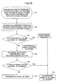
- Fig. 10 is a flowchart illustrating an example of operational procedure within the transmitter 80.
- the second system inquires the first system whether the second system is allowed to transmit at the same time.
- the first system can ask the same question to the second system.
- the first system is a desired system and the second system is an interfering system. This inquiry can be sent via any kind of control channel between systems.
- the interference condition detector 87 detects interference conditions. For example, the interference condition detector 87 stops the first system signal transmission and the second system transmits a signal temporarily, the interference condition detector 87 receives the second system's signal and measures signal strength and frequencies, etc. thereof.
- the determiner 88 determines whether the second system is allowed to transmit signals at the same time as the first system transmission. For example, when the signal strength of the received signal from the interfering system is smaller than a predetermined value, or the separation between the central frequencies of the desired and interfering systems is larger than a predetermined value, it is expected that no large interference will occur between both the systems even if they transmit signals simultaneously. In this case, the procedure goes to step 104, where the desired system sends a notice to the interfering system that the simultaneous transmission is allowed.
- the procedure goes to step 105.
- the transfer characteristics (e.g., filter shape) of the shaping filter 82 to be used for transmission are adjusted.
- a shaping filter having suitable transfer characteristics is selected. Concrete filter shapes are explained later.
- step 106 after the filter adjustment at step 105, it is determined whether the second system is allowed to transmit simultaneously. If it is determined that the second system is allowed to transmit, the procedure goes to step 104, and signal communication starts by using a modified filter shape. If the simultaneous signal transmission is still not allowed, the procedure goes to step 107.
- the determiner 88 sends a notice to the other interfering system that it is not allowed to transmit simultaneously.
- the interfering system gives up simultaneous transmission.
- the interfering system can transmit in a different time slot.
- the desired system can give up signal transmission.
- the priority between the systems can be considered.
- the transfer characteristics of the shaping filter 82 are properly adjusted.
- Signal band-pass-filtering is performed by the transmission shaping filter and a receiver shaping filter as a pair. Accordingly, a receiver shaping filter corresponding to the transmission shaping filter 82 is provided in the receiver side, not shown.
- the transfer characteristics of the receiver shaping filter can also be adjusted.
- the transfer characteristics of the shaping filter is explained.
- the center carrier frequencies of the desired system and the interfering system are measured, and their difference is large.
- the transmission shaping filter 82 and the shaping receiver filter are root raised cosine filters that can modify their roll-off rates.
- Fig. 11 shows typical frequency spectra of the desired signal and the interfering signal after passing the shaping filters. It is assumed that the roll-off rates of the filters used in the desired and interfering systems are both 1.0 before adjustment. Therefore, the filters have transfer characteristics twice the Nyquist frequencies.
- the transmission interval of the desired system is T 1
- the transmission interval of the interfering system is T 2
- the separation between their carrier frequencies is ⁇ f .
- the receiver receives both the signals, which overlap on the frequency axis as shown in Fig. 11(A).
- This kind of condition is grasped by the interference condition detector 87 and the determiner 88 shown in Fig. 9 at steps 102 and 103 shown in Fig. 10.
- Fig. 12 illustrates the principle of estimating an amount of interference.
- the shapes of frequency spectra shown in Fig. 12 are the same as those shown in Fig. 11.
- the amount of interference is evaluated by an overlapped area, which is approximated by a triangle (I) of broken lines in Fig. 12(A).
- the interference is considered to be beyond tolerance.
- this embodiment makes the roll-off rates of the filters smaller.
- the roll-off rates are both changed to 0.2.
- Fig. 11(B) shows the signal spectra that have passed the filters with the changed roll-off rates.
- the shaping filters used for communication in the first and second systems have transfer characteristics of 1.2/T_1 and 1.2/T2, respectively.
- the amount of interference is evaluated by an area of a triangle (I') shown in Fig. 12 (B). By changing the roll-off rates of the shaping filters, the area of the triangle is changed from (I) to (I'), which shows the reduction of the amount of interference.
- Fig. 13 illustrates simulation results of average bit error rates (BER) of the first system signal before and after the change of the roll-off rates of the shaping filters.
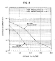
- Fig. 14 illustrates simulation results of average bit error rates (BER) of the interfering signal before and after the change of the roll-off rates of the filters.
- the conditions of simulations shown in Figs. 13 and 14 are shown in Fig. 15.
- Figs. 11 and 12 show that the interference can be suppressed to obtain good average bit error rates (BER) by making the roll-off rates of the filters smaller for the same E b /N o value.
- the transfer characteristics of the shaping filter 82 is properly adjusted. Band-pass-filtering is performed by a pair of the transmission shaping filter and the receiver shaping filter. The transfer characteristics of the receiver shaping filter may also be adjusted.
- a frequency shift filter is used as an adaptive filter shown in Fig. 1 to cancel interference when the adjustment of the transfer characteristics of the transmission shaping filter and the receiver shaping filter is not enough to realize adequate cancellation reduction.
- the difference is measured at step 102 in Fig. 10.
- a frequency shift filter used in the receiver as an adaptive filter is shown in Fig. 16.
- the frequency shift filter has three branches, summing unit 164 for summing (combining) signals from all branches, and an error signal generator 165.
- the error signal generator 165 outputs the difference between the output from the summing unit 164 and the desired signal (for example, training signal).
- the branches 1, 2 and 3 are provided with FSE filters 161, 162 and 163, respectively.
- the branches 2 and 3 are further provided with phase adjusters 167 and 168, respectively, which adjust a phase rotation amount.
- Each of the FSE filters 161, 162 and 163 has functions and structure as shown in Fig. 7.
- the phase adjuster 167 provided in the branch 2 shifts the center frequency of an input signal x(t) to the plus (positive) direction by twice the Nyquist frequency (i.e., +1/T 1 ).
- the phase adjuster 168 provided in the branch 3 shifts the center frequency of an input signal x(t) to the minus (negative) direction by twice the Nyquist frequency (i.e., -1/T 1 ).
- Fig. 17 shows the signal spectrum appearing in the branches 1 and 2 before summing by the summing unit 164.
- a solid line wave shape represents a desired signal
- a broken line wave shape represents an interfering signal.
- the phase adjuster 167 in the branch 2 shifts the central frequency of the input signal x(t) by 1/T 1 . Therefore, the signal spectrum appearing in the branch 2 is shifted in the frequency axis by 1/T 1 as shown in a lower chart of Fig. 17.
- These signals shifted by 1/T 1 have large correlation due to digital filter characteristics (1/T 1 is a cyclic frequency for the desired signal). Therefore, the sum of the signals from the FSE filters 161, 162 becomes a large signal if the interfering signal does not exist.
- Fig. 18 is similar to Fig. 17, and shows the signal spectra appearing in the branches 1 and 3 before summing by the summing unit 164.
- the signal spectrum appearing in the branch 3 is shifted in the frequency axis by 1/T 1 as shown in a lower chart of Fig. 18.
- These signals shifted by 1/T 1 also have large correlation due to digital signal characteristics (i.e., the property of cyclostationarity). Therefore, the sum of the signals from the FSE filters 161, 163 becomes a large signal if the interfering signal does not exist.
- An output from the summing unit 164 is input to the error signal generator 165.
- the error signal generator 165 outputs a difference between the output signal from the summing unit 164 and the desired signal (training signal) as an error signal.
- each of the FSE filters 161, 162 and 163 are adaptively adjusted and updated so as to reduce the error signal, and this operation is repeated. If each FSE filter's coefficients can be adjusted so that the output signal from the summing unit 164 becomes large enough, it is considered that interference by the interfering signal is suppressed well enough.
- a rectangular filter as shown in Fig. 19 is used instead of a root raised cosine filter.
- the rectangular filter shown in Fig. 19 is a preferable low pass filter having a pass band of twice the Nyquist frequency band.
- this rectangular filter is used as a transmission/receiving shaping filter for the desired signal.
- Fig. 20 shows a desired signal and an interfering signal in a case where the separation ⁇ f between carrier frequencies is smaller than the Nyquist frequency 1/2T 1 .
- Fig. 20(A) shows the signal spectrum in a case where the first and second systems both use a root raised cosine filter, and represents wave forms the same as Fig. 17(A).
- FIG. 20(B) shows the signal spectrum in a case where the first system uses a rectangular filter and the second system uses a root raised cosine filter, and represents wave forms the same as Fig. 19.
- Fig. 20 in the case where the rectangular filter is used, amplitude is large even in the frequency region beyond the Nyquist frequency band (1/2T 1 ), and the correlation between the branches 1 and 2 and the correlation between the branches 1 and 3 become larger than that in the third embodiment. Therefore, such rectangular shaping filters result in increasing spectrum redundancy which can be exploited by FSE and FRESH adaptive filters at the received side to cancel interference much more effectively.
- Fig. 21 shows signals appearing in the branch 1 and the branch 2 in the case where the rectangular filter is used.
- Fig. 22 shows signals appearing in the branch 1 and the branch 3.
- the preferable rectangular filter is used in this embodiment, but other types of filter can be used.
- a filter having large amplitude characteristics in the frequency region exceeding the Nyquist frequency 1/2T 1 can be used.
- Another transmission shaping filter that has large amplitude characteristics in the frequency region beyond the Nyquist frequency 1/2T 1 , and preferably does not allow inter-symbol interference to occur, when multiplied by the receiver shaping filter, can be used.
- Fig. 23 illustrates simulation results of average bit error rates in a case where shaping filters used in transmission and reception are changed in various ways.
- Fig. 23 represents the simulation results of the first (desired) system signal.
- Fig. 24 represents the simulation results of the second (interfering) system signal.
- Figs. 23 and 24 show simulation results in the following cases:
Landscapes
- Engineering & Computer Science (AREA)
- Computer Networks & Wireless Communication (AREA)
- Signal Processing (AREA)
- Power Engineering (AREA)
- Physics & Mathematics (AREA)
- Spectroscopy & Molecular Physics (AREA)
- Noise Elimination (AREA)
- Transmitters (AREA)
Abstract
Description
- The present invention generally relates to radio communication, and especially relates to a communication device and method used under a frequency sharing environment where plural communication systems establish communications within the same frequency band.
- In the prior art radio communication systems, a dedicated frequency band is allocated to each radio communication system so as to avoid interference and maintain signal qualities. However, in order to use frequency resources much more efficiently, a frequency sharing environment is considered, in which plural communication systems share the same frequency bands. In such a frequency sharing environment, it is required that own system suppresses interfering signals from other systems to maintain the signal quality of desired signals for the own system.
- Fig. 1 shows an example of two transmitters and a receiver that would be used in such a system. In the example shown in Fig. 1, two transmitters use the same frequency band, but a
user 1 and auser 2 utilize different communication systems. A signal transmitted from theuser 2 becomes an interfering signal against theuser 1. In the prior art radio communication system, atransmission shaping filter 1 in the transmitter for theuser 1 and areceiver shaping filter 3 in a receiver for theuser 1 make a pair and their filter transfer characteristics are fixed so as to perform suitable band pass limitation. - Fig. 2 shows frequency spectrum charts illustrating a desired signal. A1 represents a baseband signal (frequency spectrum) of impulse series of a modulated signal for
user 1. B1 represents a baseband signal frequency spectrum ofuser 1 that has been bandpass-filtered by a transmission shaping filter (e.g., a root-raised cosine filter). C1 represents a frequency spectrum of an RF transmission signal transmitted from theuser 1. The desired signal transmitted byuser 1 has a carrier frequency of f1. The desired signal is transmitted with a symbol interval of T1, and thus its Nyquist frequency is 1/2T1. - Fig. 3 shows frequency spectrum charts illustrating an undesired (interfering) signal. A2 represents a baseband signal (frequency spectrum) of impulse series of a modulated signal for
user 2. B2 represents a baseband signal frequency spectrum ofuser 2 that has been bandpass-filtered by a transmission shaping filter (e.g., a root-raised cosine filter). C2 represents a frequency spectrum of an RF transmission signal transmitted from theuser 2. The undesired (interfering) signal transmitted byuser 2 has a carrier frequency of f2. The undesired signal is transmitted with a symbol interval of T2, and thus its Nyquist frequency is 1/2T2. - Fig. 4 shows frequency charts illustrating a desired signal. D represents a frequency spectrum of signals received by the receiver for the
user 1. The total spectrum (solid line) of the received signal is considered to consist of a desired signal (1), an undesired signal (2) and noise (3). E represents a frequency spectrum of signals converted from RF to baseband. F represents a frequency spectrum of signals after bandpass filtering by areceiver shaping filter 3 in the receiver for theuser 1. - Fig. 5 shows frequency charts illustrating a desired signal that has been ideally equalized. G represents the frequency spectrum of a desired signal after being ideally equalized by an adaptive filter in the receiver for the
user 1. The signal shown in Fig. 5G is symbol-rate-sampled to repeatedly appear with intervals of 1/T1 in the frequency domain as shown in Fig. 5H. The summation of these frequency spectrum signals yields a restored signal (Fig. 5I) that corresponds to the transmitted signal from theuser 1. The signals indicated by A1, B1, C1, ... in Figs. 2-5 correspond to signals indicated by the same reference characters in Fig. 1. - One method for cancelling another system's interfering signals in received signals is known, in which Maximum Likelihood Sequence or Linear signal processing is employed to jointly or sequentially process the signals, respectively. These methods, however, require that the desired system grasps the parameters (training symbol, modulation method, symbol rate, etc.) of the interfering system in advance. When such parameters of the interfering system are unknown, it is impossible to effectively cancel the interfering signals.
- Another method for cancelling another system's interfering signals in received signals is known, in which the Fractionally Spaced Equalizer (FSE) and the FREquency Shift filtering (FRESH) are employed. FSE and FRESH filtering schemes have the potential to exploit the spectrum redundancy for interference cancellation with no need for interfering system signal's parameters. Fig. 6 schematically shows a frequency shift filter (FRESH). Fig. 7 schematically shows a fractionally spaced equalizer (FSE). The FSE and FRESH can be used as an adaptive filter for the receiver as shown in Fig. 1. As shown in Fig. 6, the FRESH includes a plurality of FSEs connected in parallel, and the outputs of the FSEs are summed. The output after the summation is subtracted from a training signal to generate an error signal. The tap coefficients of all FSE filters are jointly adjusted so as to reduce the error signal. As shown in Fig. 7, the FSE filter includes a series of delay elements, each of which delays an over-sampled input signal. Each output from each of the delay elements is multiplied with a tap coefficient (i.e, weight) ci and summed (see Non-Patent
Documents # 1, #2). - W. A. Gardner, "Exploitation of spectral redundancy" in cyclostationary signals", IEEE Signal Processing Magazine, vol.8, no.2, pp.14-36, Apr. 1991
- W. A. Gardner, "Cyclic Wiener filtering: theory and method", IEEE Trans. commun., vol.41, no.1, pp.151-163, Jan. 1993
- In the above prior art, the
transmission shaping filter 1 and thereceiver shaping filter 3 shown in Fig. 1 make a pair and their shapes and characteristics are fixed when designing the system so as to be matched filters. On the other hand, dynamic compensation such as compensation for channel variations exclusively relies on the adaptive filter at the receiver side. Therefore, when the desired signal is subject to interference a concern is that interference cancellation ability becomes inadequate especially in case of significant interference and when the signal parameters of undesired signals are unknown, non-parametric interference cancellation is needed. Furthermore, the performance of non-parametric interference cancellation based on FSE and FRESH adaptive filters, largely depends on the amount of spectrum redundancy available and/or the carrier frequency separation between the desired and interfering signals. - The present invention provides a communication device and method used in a first communication system under a frequency sharing environment where a first communication system and a second communication system establish communications within the same frequency band, in which another system's interference can be reduced even without knowing its system's parameters.
- Features of the present invention are set forth in the description that follows, and in part will become apparent from the description and the accompanying drawings, or may be learned by practice of the invention according to the teachings provided in the description. Problem solutions provided by the present invention will be realized and attained by a communication device and method particularly pointed out in the specification in such full, clear, concise, and exact terms as to enable a person having ordinary skill in the art to practice the invention.
- To achieve these solutions and in accordance with the purpose of the invention, as embodied and broadly described herein, the invention provides a specific communication device and method as follows.
- An aspect of the present invention provides a communication device used in a first communication system under a frequency sharing environment where a first communication system and a second communication system establish communications within the same frequency band, comprising: a detector for detecting an interfering signal from the second communication system; and a determiner for determining transfer characteristics of a shaping filter according to a result of the detection, the shaping filter being used for a desired signal of the first communication system.
- Another aspect of the present invention provides a communication method used in a first communication system under a frequency sharing environment where the first communication system and a second communication system establish communications within the same frequency band, comprising the steps of: detecting an interfering signal from the second communication system; and determining transfer characteristics of a shaping filter according to a result of the detection, the shaping filter being used for a desired signal of the first communication system.
- According to embodiments of the present invention, in a communication device and method used in an own communication system under a frequency sharing environment where the own communication system and another communication system establish communications within the same frequency band, the other system's interference can be reduced even without knowing the other system's parameters to reduce degradation of the own system's receiver performance. Interference of the own system on the other system can also be reduced.
-
- Fig. 1 is a schematic diagram of transmitters and a receiver used in a frequency sharing environment;
- Fig. 2 shows frequency spectrum charts illustrating a desired signal;
- Fig. 3 shows frequency spectrum charts illustrating an undesired (interfering) signal;
- Fig. 4 shows frequency charts illustrating a desired signal;
- Fig. 5 shows frequency charts illustrating a desired signal that has been ideally equalized;
- Fig. 6 is a schematic diagram illustrating the principle of a frequency shift filter (FRESH);
- Fig. 7 is a schematic diagram illustrating the principle of a fractionally spaced equalizer (FSE);
- Fig. 8 is a block diagram illustrating a transmitter according to an embodiment of the present invention;
- Fig. 9 is a block diagram similar to Fig. 8, illustrating that own system and another system are exchanging information with each other;
- Fig. 10 is a flowchart illustrating a transmitter procedure according to the embodiment of the present invention;
- Fig. 11 shows frequency spectrum charts illustrating a desired signal and an interfering signal;
- Fig. 12 shows frequency spectrum charts illustrating a desired signal and an interfering signal;
- Fig. 13 is a chart illustrating simulation results of average bit error rates of the first system;
- Fig. 14 is a chart illustrating simulation results of average bit error rates of the second system;
- Fig. 15 shows simulation conditions;
- Fig. 16 is a schematic diagram illustrating a frequency shift filter;
- Fig. 17 shows two signals before frequency shift filter summing;
- Fig. 18 shows two signals before frequency shift filter summing;
- Fig. 19 is a frequency spectrum chart when a rectangular filter is used;
- Fig. 20 shows frequency spectrum charts illustrating transfer characteristics of a root raised cosine shaping filter and a rectangular shaping filter;
- Fig. 21 shows two signals before frequency shift filter summing;
- Fig. 22 shows two signals before frequency shift filter summing;
- Fig. 23 is a chart illustrating simulation results of average bit error rates of an own system signal; and
- Fig. 24 is a chart illustrating simulation results of average bit error rates of another system signal.
- In the following, embodiments of the present invention are described with reference to the accompanying drawings, wherein common reference numbers are assigned to items that have the same functions, and the descriptions are not repeated.
- According to one embodiment of the present invention, a transmitter's shaping filter and a receiver's shaping filter are adaptively modified depending on interference conditions to maintain interference cancellation capability of the receiver. When the separation between the central carrier frequencies of a desired signal and an undesired signal is large, transfer characteristics of the shaping filters are narrowed in the frequency domain or the symbol rate is lowered to reduce the signal's spectral redundancy and narrow the signal band pass, and therefore avoid interference. The filters used for communication may be a low pass filter that has odd-symmetric (i.e., anti-symmetric) transfer characteristics with respect to the Nyquist frequency. A raised cosine filter having a changeable roll-off rate can also be used. The desired signal and the undesired signal can be properly separated by decreasing the roll-off rate.
- On the other hand, when the separation between the central carrier frequencies of the desired signal and the undesired signal is small, the shaping filter's transfer characteristics in the frequency region beyond the Nyquist frequency are made larger in order to increase spectrum redundancy such that an effective suppression of interfering signals can be made.
- The transmission and receiving shaping filters may have amplitude characteristics larger than that of a roll-off filter in the frequency range beyond the Nyquist frequency. Such a shaping filter may be a low pass filter, preferably a rectangular filter having a passband that is more than twice the Nyquist frequency.
- To exploit the spectrum redundancy induced by the pulse shaping filters for non-parametric interference cancellation at the receiver side, FSE or FRESH filter can be used as an adaptive filter. For the FRESH filter a plurality of adaptive filters, the center frequencies of which have different transfer characteristics, and an adjuster for adaptively adjusting the coefficients of one or more adaptive filters based on outputs from the plural filters and a known signal. The central frequencies of the plural filters may be separated from a reference adaptive filter (medium branch) by twice the Nyquist frequency (i.e., cyclic frequency). Outputs of filters in which phases are shifted by the cyclic frequency have large correlation with each other. Adaptively updating the filter coefficients so as to increase such correlation (so as to decrease differences from the known signal), makes it possible to obtain an interference-suppressed received signal. Irrespective of whether the central frequencies are large or small, good signal separation characteristics can be maintained and frequency utilization efficiency is improved under the frequency sharing environment where the plural communication systems share the same frequency band.
- Fig. 8 shows a block diagram illustrating a transmitter according to an embodiment of the present invention. The
transmitter 80 includes atransmission signal generator 81, atransmission shaping filter 82, a digital-to-analog (D/A)converter 83, anamplifier 85, anantenna 86, aninterference condition detector 87 and adeterminer 88. Thetransmission signal generator 81 generates a baseband transmission signal as shown in Fig. 2A. Thetransmission shaping filter 82 band-pass-filters the transmission signal. The transfer characteristics of this shapingfilter 82 are properly set according to control information. The D/A converter 83 converts the baseband digital signal to an analog signal. Themixer 84 frequency-converts the analog signal with carrier frequency f1 of a desired signal. Theamplifier 85 amplifies power of the frequency converted signal so as to transmit it from theantenna 86. Theinterference condition detector 87 detects parameters (such as frequency, power, etc.) of an interference (undesired) signal from another system. In order to detect them, a received signal is used to estimate conditions of an interference signal. When thetransmitter 80 is connected to a transmitter of an interfering second system via a wired network, detection can be performed by receiving control signals from the interfering transmitter. Thedeterminer 88 determines transfer characteristics of thefilter 82 based on the detected results. In this embodiment, the first system and the second system sharing the same frequency band communicate with each other so as to adjust their shaping filters to prevent interference. Thetransmission shaping filter 82 and a receiver shaping filter (not shown) in a receiver side make a pair to band-pass-filter the signal to be transmitted and received. - Operations are explained with reference to Figs. 9 and 10. Fig. 9 illustrates how to determine transfer characteristics of the
transmission shaping filter 82, based on communication between the first system and the second system. Fig. 10 is a flowchart illustrating an example of operational procedure within thetransmitter 80. - At
step 101, the second system inquires the first system whether the second system is allowed to transmit at the same time. Of course, the first system can ask the same question to the second system. For the purpose of convenience, the first system is a desired system and the second system is an interfering system. This inquiry can be sent via any kind of control channel between systems. - At
step 102, theinterference condition detector 87 detects interference conditions. For example, theinterference condition detector 87 stops the first system signal transmission and the second system transmits a signal temporarily, theinterference condition detector 87 receives the second system's signal and measures signal strength and frequencies, etc. thereof. - At
step 103, thedeterminer 88 determines whether the second system is allowed to transmit signals at the same time as the first system transmission. For example, when the signal strength of the received signal from the interfering system is smaller than a predetermined value, or the separation between the central frequencies of the desired and interfering systems is larger than a predetermined value, it is expected that no large interference will occur between both the systems even if they transmit signals simultaneously. In this case, the procedure goes to step 104, where the desired system sends a notice to the interfering system that the simultaneous transmission is allowed. - On the other hand, when the signal strength of the received signal from the interfering system is larger than the predetermined value or the separation between the central frequencies of the desired and interfering systems is smaller than the predetermined value, large interference between the systems may occur if both the systems transmit signals simultaneously. In this case, the procedure goes to step 105.
- At
step 105, the transfer characteristics (e.g., filter shape) of the shapingfilter 82 to be used for transmission are adjusted. Alternatively, a shaping filter having suitable transfer characteristics is selected. Concrete filter shapes are explained later. - At
step 106, after the filter adjustment atstep 105, it is determined whether the second system is allowed to transmit simultaneously. If it is determined that the second system is allowed to transmit, the procedure goes to step 104, and signal communication starts by using a modified filter shape. If the simultaneous signal transmission is still not allowed, the procedure goes to step 107. - At
step 107, thedeterminer 88 sends a notice to the other interfering system that it is not allowed to transmit simultaneously. In this case, the interfering system gives up simultaneous transmission. The interfering system can transmit in a different time slot. Alternatively, the desired system can give up signal transmission. As a criterion for determining whether to give up or not, the priority between the systems can be considered. - In a case where large interference occurs between the first and second systems when they simultaneously transmit signals, the transfer characteristics of the shaping
filter 82 are properly adjusted. Signal band-pass-filtering is performed by the transmission shaping filter and a receiver shaping filter as a pair. Accordingly, a receiver shaping filter corresponding to thetransmission shaping filter 82 is provided in the receiver side, not shown. The transfer characteristics of the receiver shaping filter can also be adjusted. - In the second embodiment, one example of adjustment of the transfer characteristics of the shaping filter is explained. In the explanation below, it is assumed that the center carrier frequencies of the desired system and the interfering system are measured, and their difference is large. It is also assumed that the
transmission shaping filter 82 and the shaping receiver filter are root raised cosine filters that can modify their roll-off rates. - Fig. 11 shows typical frequency spectra of the desired signal and the interfering signal after passing the shaping filters. It is assumed that the roll-off rates of the filters used in the desired and interfering systems are both 1.0 before adjustment. Therefore, the filters have transfer characteristics twice the Nyquist frequencies. The transmission interval of the desired system is T1, and the shaping filter in the desired system has a bandwidth of 2 x 1/T1 = 2/T1. The transmission interval of the interfering system is T2, and the shaping filter in the interfering system has a bandwidth of 2 x 1/T2 = 2/T2. The separation between their carrier frequencies is Δf. In this case, when both the systems transmit signals simultaneously, the receiver receives both the signals, which overlap on the frequency axis as shown in Fig. 11(A). This kind of condition is grasped by the
interference condition detector 87 and thedeterminer 88 shown in Fig. 9 atsteps - Fig. 12 illustrates the principle of estimating an amount of interference. The shapes of frequency spectra shown in Fig. 12 are the same as those shown in Fig. 11. The amount of interference is evaluated by an overlapped area, which is approximated by a triangle (I) of broken lines in Fig. 12(A). When the triangle area (I) is larger than a predetermined value, the interference is considered to be beyond tolerance. In this case, this embodiment makes the roll-off rates of the filters smaller. In the example shown in Figs. 11 and 12, the roll-off rates are both changed to 0.2. Fig. 11(B) shows the signal spectra that have passed the filters with the changed roll-off rates. The shaping filters used for communication in the first and second systems have transfer characteristics of 1.2/T_1 and 1.2/T2, respectively. The amount of interference is evaluated by an area of a triangle (I') shown in Fig. 12 (B). By changing the roll-off rates of the shaping filters, the area of the triangle is changed from (I) to (I'), which shows the reduction of the amount of interference.
- Fig. 13 illustrates simulation results of average bit error rates (BER) of the first system signal before and after the change of the roll-off rates of the shaping filters. Fig. 14 illustrates simulation results of average bit error rates (BER) of the interfering signal before and after the change of the roll-off rates of the filters. The conditions of simulations shown in Figs. 13 and 14 are shown in Fig. 15. Figs. 11 and 12 show that the interference can be suppressed to obtain good average bit error rates (BER) by making the roll-off rates of the filters smaller for the same Eb/No value.
- In a case where large interferences occur when the first and second systems simultaneously transmit in the same frequency band, the transfer characteristics of the shaping
filter 82 is properly adjusted. Band-pass-filtering is performed by a pair of the transmission shaping filter and the receiver shaping filter. The transfer characteristics of the receiver shaping filter may also be adjusted. In this third embodiment, a frequency shift filter is used as an adaptive filter shown in Fig. 1 to cancel interference when the adjustment of the transfer characteristics of the transmission shaping filter and the receiver shaping filter is not enough to realize adequate cancellation reduction. In the explanation below, it is assumed that the difference (separation) between the central carrier frequencies of the desired and interfering systems is smaller than a predetermined value. The difference is measured atstep 102 in Fig. 10. A frequency shift filter used in the receiver as an adaptive filter is shown in Fig. 16. The frequency shift filter has three branches, summingunit 164 for summing (combining) signals from all branches, and anerror signal generator 165. Theerror signal generator 165 outputs the difference between the output from the summingunit 164 and the desired signal (for example, training signal). Thebranches FSE filters branches phase adjusters phase adjuster 167 provided in thebranch 2 shifts the center frequency of an input signal x(t) to the plus (positive) direction by twice the Nyquist frequency (i.e., +1/T1). Thephase adjuster 168 provided in thebranch 3 shifts the center frequency of an input signal x(t) to the minus (negative) direction by twice the Nyquist frequency (i.e., -1/T1). - Fig. 17 shows the signal spectrum appearing in the
branches unit 164. A solid line wave shape represents a desired signal, and a broken line wave shape represents an interfering signal. In this embodiment, since the carrier frequency separation Δf is smaller than a predetermined value, the method explained in the second embodiment does not cancel the interference well enough. Thephase adjuster 167 in thebranch 2 shifts the central frequency of the input signal x(t) by 1/T1. Therefore, the signal spectrum appearing in thebranch 2 is shifted in the frequency axis by 1/T1 as shown in a lower chart of Fig. 17. These signals shifted by 1/T1 have large correlation due to digital filter characteristics (1/T1 is a cyclic frequency for the desired signal). Therefore, the sum of the signals from the FSE filters 161, 162 becomes a large signal if the interfering signal does not exist. - Fig. 18 is similar to Fig. 17, and shows the signal spectra appearing in the
branches unit 164. The signal spectrum appearing in thebranch 3 is shifted in the frequency axis by 1/T1 as shown in a lower chart of Fig. 18. These signals shifted by 1/T1 also have large correlation due to digital signal characteristics (i.e., the property of cyclostationarity). Therefore, the sum of the signals from the FSE filters 161, 163 becomes a large signal if the interfering signal does not exist. - An output from the summing
unit 164 is input to theerror signal generator 165. Theerror signal generator 165 outputs a difference between the output signal from the summingunit 164 and the desired signal (training signal) as an error signal. - The filter coefficients of each of the FSE filters 161, 162 and 163 are adaptively adjusted and updated so as to reduce the error signal, and this operation is repeated. If each FSE filter's coefficients can be adjusted so that the output signal from the summing
unit 164 becomes large enough, it is considered that interference by the interfering signal is suppressed well enough. - In the four embodiment of the present invention, a rectangular filter as shown in Fig. 19 is used instead of a root raised cosine filter. The rectangular filter shown in Fig. 19 is a preferable low pass filter having a pass band of twice the Nyquist frequency band. In this embodiment, this rectangular filter is used as a transmission/receiving shaping filter for the desired signal. Fig. 20 shows a desired signal and an interfering signal in a case where the separation Δf between carrier frequencies is smaller than the
Nyquist frequency 1/2T1. Fig. 20(A) shows the signal spectrum in a case where the first and second systems both use a root raised cosine filter, and represents wave forms the same as Fig. 17(A). Fig. 20(B) shows the signal spectrum in a case where the first system uses a rectangular filter and the second system uses a root raised cosine filter, and represents wave forms the same as Fig. 19. As clearly seen from Fig. 20, in the case where the rectangular filter is used, amplitude is large even in the frequency region beyond the Nyquist frequency band (1/2T1), and the correlation between thebranches branches - Fig. 21 shows signals appearing in the
branch 1 and thebranch 2 in the case where the rectangular filter is used. Fig. 22 shows signals appearing in thebranch 1 and thebranch 3. - The preferable rectangular filter is used in this embodiment, but other types of filter can be used. For example, a filter having large amplitude characteristics in the frequency region exceeding the
Nyquist frequency 1/2T1 can be used. Another transmission shaping filter that has large amplitude characteristics in the frequency region beyond theNyquist frequency 1/2T1, and preferably does not allow inter-symbol interference to occur, when multiplied by the receiver shaping filter, can be used. - Fig. 23 illustrates simulation results of average bit error rates in a case where shaping filters used in transmission and reception are changed in various ways. The conditions of the simulation are the same as those of Fig. 15 except that the central carrier frequency f2 of the interfering signal is the same as the central carrier frequency f1 of the desired signal (Δf = 0). Fig. 23 represents the simulation results of the first (desired) system signal. Fig. 24 represents the simulation results of the second (interfering) system signal. Figs. 23 and 24 show simulation results in the following cases:
- (1) A case where the desired signal uses a root raised cosine filter having a roll-off rate of 1.0 as a transmission shaping filter, the interfering signal also uses a root raised cosine filter having a roll-off rate of 1.0 as a transmission shaping filter, and FSE is used as an adaptive filter (FSE RRC/RRC);
- (2) A case where the desired signal uses a root raised cosine filter having a roll-off rate of 1.0 as a transmission shaping filter, the interfering signal also uses a root raised cosine filter having a roll-off rate of 1.0 as a transmission shaping filter, and FRESH is used as an adaptive filter (FRESH RRC/RRC);
- (3) A case where the desired signal uses a rectangular filter having a pass band twice the Nyquist frequency band as a transmission shaping filter, the interfering signal uses a root raised cosine filter having a roll-off rate of 1.0 as a transmission shaping filter, and FSE is used as an adaptive filter (FSE Rect/RRC);
- (4) A case where the desired signal uses a rectangular filter having a pass band twice the Nyquist frequency band as a transmission shaping filter, the interfering signal uses a root raised cosine filter having a roll-off rate of 1.0 as a transmission shaping filter, and FRESH is used as an adaptive filter (FRESH Rect/RRC);
- (5) A case where the desired signal uses a root raised cosine filter having a roll-off rate of 1.0 as a transmission shaping filter, the interfering signal uses a rectangular filter having a pass band twice the Nyquist frequency band as a transmission shaping filter, and FSE is used as an adaptive filter (FSE RRC/Rect);
- (6) A case where the desired signal uses a root raised cosine filter having a roll-off rate of 1.0 as a transmission shaping filter, the interfering signal uses a rectangular filter having a pass band twice the Nyquist frequency band as a transmission shaping filter, and FRESH is used as an adaptive filter (FRESH RRC/Rect);
- (7) A case where the desired signal and the interfering signal both use a rectangular filter having a pass band twice the Nyquist frequency band as a transmission shaping filter, and FSE is used as an adaptive filter (FSE Rect/Rect); and
- (7) A case where the desired signal and the interfering signal both use a rectangular filter having a pass band twice the Nyquist frequency band as a transmission shaping filter, and FRESH is used as an adaptive filter (FRESH Rect/Rect).
- As shown in Figs. 23 and 24, the use of the rectangular filter gives a better average bit error rate.
- The present invention is not limited to these embodiments, but variations and modifications may be made without departing from the scope of the present invention.
Claims (8)
- A communication device (80) used in a first communication system under a frequency sharing environment where the first communication system and a second communication system establish communications within the same frequency band, characterized by:a detector (87) for detecting an interfering signal from the second communication system; anda determiner (88) for determining transfer characteristics of a shaping filter (82) according to a result of the detection, the shaping filter being used for a desired signal of the first communication system.
- The communication device as claimed in claim 1, characterized in that
the shaping filter is a low pass filter able to change a signal pass band thereof. - The communication device as claimed in claim 2, characterized in that
the shaping filter is a root raised cosine filter able to change a roll-off rate thereof. - The communication device as claimed in claim 2, characterized in that
the shaping filter has amplitude characteristics larger than those of a root raised cosine filter in frequency range beyond the Nyquist frequency. - The communication device as claimed in claim 2, characterized in that
the shaping filter is a rectangular filter through which a band having twice the Nyquist frequency or more passes. - The communication device as claimed in claim 2, characterized by:a plurality of adaptive filters, said filters having different central frequencies of transfer characteristics; andan adjuster for adaptively adjusting a filter coefficients of one or more of said filters, based on a predetermined signal and outputs from said adaptive filters.
- The communication device as claimed in claim 2, characterized in:the central frequencies of transfer characteristics of said adaptive filters are separated by twice the Nyquist frequency.
- A communication method used in a first communication system under a frequency sharing environment where the first communication system and a second communication system establish communications within the same frequency band, characterized by the steps of:detecting an interfering signal from the second communication system; anddetermining transfer characteristics of a shaping filter according to a result of the detection, the filter being used for a desired signal of the first communication system.
Applications Claiming Priority (1)
| Application Number | Priority Date | Filing Date | Title |
|---|---|---|---|
| JP2005179894A JP4614829B2 (en) | 2005-06-20 | 2005-06-20 | Communication apparatus and communication method |
Publications (3)
| Publication Number | Publication Date |
|---|---|
| EP1737134A2 true EP1737134A2 (en) | 2006-12-27 |
| EP1737134A3 EP1737134A3 (en) | 2008-09-03 |
| EP1737134B1 EP1737134B1 (en) | 2014-07-16 |
Family
ID=37074731
Family Applications (1)
| Application Number | Title | Priority Date | Filing Date |
|---|---|---|---|
| EP06253187.6A Ceased EP1737134B1 (en) | 2005-06-20 | 2006-06-20 | Adaptive pulse shaping filter based on interference detection |
Country Status (4)
| Country | Link |
|---|---|
| US (1) | US7773948B2 (en) |
| EP (1) | EP1737134B1 (en) |
| JP (1) | JP4614829B2 (en) |
| CN (1) | CN1885984B (en) |
Cited By (5)
| Publication number | Priority date | Publication date | Assignee | Title |
|---|---|---|---|---|
| CN103716269A (en) * | 2012-10-05 | 2014-04-09 | 诺基亚西门子通信公司 | Methods and apparatus for signal filtering |
| CN105207962A (en) * | 2015-06-28 | 2015-12-30 | 知鑫知识产权服务(上海)有限公司 | Interference signal searching method with high frequency precision |
| WO2017194167A1 (en) * | 2016-05-13 | 2017-11-16 | Huawei Technologies Co., Ltd. | Radio transceiving device and method using waveform adaptation |
| EP3734921A1 (en) * | 2019-04-30 | 2020-11-04 | Juniper Networks, Inc. | Methods and apparatus for optical communications via pulse amplitude modulation (pam) in dense wavelength-division multiplexing (dwdm) systems |
| US11522616B2 (en) | 2019-04-30 | 2022-12-06 | Juniper Networks, Inc. | Methods and apparatus for optical communications via pulse amplitude modulation (PAM) in dense wavelength-division multiplexing (DWDM) systems |
Families Citing this family (12)
| Publication number | Priority date | Publication date | Assignee | Title |
|---|---|---|---|---|
| KR100530365B1 (en) * | 2003-06-19 | 2005-11-22 | 삼성전자주식회사 | UWB wireless transmitter and receiver using UWB linear FM signals having opposite slopes and method thereof |
| JP4760904B2 (en) * | 2006-02-17 | 2011-08-31 | 日本電気株式会社 | Band limiting method and wireless communication system |
| CN101622793A (en) * | 2007-03-16 | 2010-01-06 | 株式会社Ntt都科摩 | Communication system, transmitting device, receiving device and communication method |
| EP1976121A1 (en) * | 2007-03-31 | 2008-10-01 | Sony Deutschland Gmbh | Digital filter |
| US8204444B2 (en) * | 2009-02-04 | 2012-06-19 | Qualcomm Incorporated | Adjustable transmission filter responsive to internal sadio status |
| CN102123500B (en) * | 2010-01-08 | 2016-08-03 | 华为技术有限公司 | The resource allocation methods of multimode terminal and device |
| CN102281224B (en) * | 2010-06-08 | 2015-08-19 | 上海无线通信研究中心 | OFDM receiver and its implementation |
| CN102378190B (en) * | 2010-08-13 | 2015-08-12 | 中兴通讯股份有限公司 | Microcell WAP (wireless access point) and channel arrangement method, dynamic spectrum resource management system |
| US9413420B1 (en) | 2011-04-20 | 2016-08-09 | Hrl Laboratories, Llc | Adaptive interference removal for compressive signal detection and reconstruction in real time |
| US10305575B2 (en) * | 2013-01-08 | 2019-05-28 | Advanced Rf Technologies, Inc. | Mobile telecommunication repeater for canceling feedback signals |
| US10320481B2 (en) * | 2016-07-13 | 2019-06-11 | Space Systems/Loral, Llc | Flexible high throughput satellite system using optical gateways |
| DE112021006146B4 (en) * | 2021-01-28 | 2025-10-16 | Mitsubishi Electric Corporation | INFORMATION LOSS PREVENTION SHIELD DEVICE |
Citations (2)
| Publication number | Priority date | Publication date | Assignee | Title |
|---|---|---|---|---|
| WO1999025075A2 (en) | 1997-11-07 | 1999-05-20 | Koninklijke Philips Electronics N.V. | A wireless communication device |
| GB2343332A (en) | 1998-10-26 | 2000-05-03 | Roke Manor Research | Adaptive filter structures |
Family Cites Families (15)
| Publication number | Priority date | Publication date | Assignee | Title |
|---|---|---|---|---|
| FI98580C (en) * | 1991-11-14 | 1997-07-10 | Nokia Mobile Phones Ltd | Selective filtration in a cellular phone |
| US5519735A (en) * | 1994-04-28 | 1996-05-21 | Lockheed Missiles & Space Co., Inc. | Reconstructing a primary signal from many secondary signals |
| US20010055320A1 (en) * | 1994-12-15 | 2001-12-27 | Pierzga Wayne Francis | Multiplex communication |
| US6307868B1 (en) * | 1995-08-25 | 2001-10-23 | Terayon Communication Systems, Inc. | Apparatus and method for SCDMA digital data transmission using orthogonal codes and a head end modem with no tracking loops |
| JPH09270733A (en) * | 1996-03-29 | 1997-10-14 | Matsushita Electric Ind Co Ltd | Spread spectrum communication equipment |
| JPH11154880A (en) * | 1997-09-05 | 1999-06-08 | Fujitsu Ltd | Signal correction method and device, distortion compensation device, distortion compensation data creation device, and transmitter |
| JP3476662B2 (en) * | 1997-10-17 | 2003-12-10 | 富士通株式会社 | Digital mobile radio communication device |
| US6445750B1 (en) * | 1998-04-22 | 2002-09-03 | Lucent Technologies Inc. | Technique for communicating digitally modulated signals over an amplitude-modulation frequency band |
| US6233594B1 (en) * | 1998-09-23 | 2001-05-15 | Globespan, Inc. | Decimation filter for oversampling analog-to digital converter |
| US6628728B1 (en) * | 1999-04-28 | 2003-09-30 | Cyntrust Communications, Inc. | Nyquist filter and method |
| SE517039C2 (en) * | 2000-05-31 | 2002-04-02 | Bjoern Ottersten | Device and method for channel interference suppression |
| DE60131243T2 (en) * | 2000-12-19 | 2008-08-21 | Ntt Docomo Inc. | Adaptive equalization method and adaptive equalizer |
| US7215715B2 (en) * | 2001-02-06 | 2007-05-08 | Maxim Integrated Products, Inc. | System and method of signal wave shaping for spectrum control of an OFDM signal |
| US20040038693A1 (en) * | 2001-08-01 | 2004-02-26 | Kazuhito Niwano | Mobile communication system, mobile communication method, base station and mobile station |
| FI20012581A0 (en) * | 2001-12-27 | 2001-12-27 | Nokia Corp | Interference elimination method in communication system |
-
2005
- 2005-06-20 JP JP2005179894A patent/JP4614829B2/en not_active Expired - Fee Related
-
2006
- 2006-06-20 CN CN200610093081XA patent/CN1885984B/en not_active Expired - Fee Related
- 2006-06-20 US US11/455,635 patent/US7773948B2/en not_active Expired - Fee Related
- 2006-06-20 EP EP06253187.6A patent/EP1737134B1/en not_active Ceased
Patent Citations (2)
| Publication number | Priority date | Publication date | Assignee | Title |
|---|---|---|---|---|
| WO1999025075A2 (en) | 1997-11-07 | 1999-05-20 | Koninklijke Philips Electronics N.V. | A wireless communication device |
| GB2343332A (en) | 1998-10-26 | 2000-05-03 | Roke Manor Research | Adaptive filter structures |
Non-Patent Citations (4)
| Title |
|---|
| GARDNER W A ET AL.: "Making the most out of spectral redundancy in GSM: cheap CCI suppression", CONFERENCE RECORD OF THE 35TH. ASILOMAR CONFERENCE ON SIGNALS, SYSTEMS, & COMPUTERS, PACIFIC GROOVE, vol. 1, 4 November 2001 (2001-11-04), pages 883 - 889 |
| VELIANOVSKI R ET AL.: "A low-power reconfigurable digital pulse-shaping filter for an utra-tdd mobile terminal receiver", THE 2002 45TH. MIDWEST SYMPOSIUM ON CIRCUITS AND SYSTEMS. CONFERENCE PROCEEDINGS, vol. 2, 4 August 2002 (2002-08-04), pages 1 - 4 |
| W. A. GARDNER: "Exploitation of spectral redundancy" in cyclostationary signals", IEEE SIGNAL PROCESSING MAGAZINE, vol. 8, no. 2, April 1991 (1991-04-01), pages 14 - 36 |
| W.A. GARDNER: "Cycloc Wiener filtering: theory and method", IEEE TRANS. COMMUN., vol. 31, no. 1, January 1993 (1993-01-01), pages 151 - 163 |
Cited By (10)
| Publication number | Priority date | Publication date | Assignee | Title |
|---|---|---|---|---|
| CN103716269A (en) * | 2012-10-05 | 2014-04-09 | 诺基亚西门子通信公司 | Methods and apparatus for signal filtering |
| EP2717527A3 (en) * | 2012-10-05 | 2015-11-25 | Nokia Solutions and Networks Oy | Methods and apparatus for signal filtering |
| CN103716269B (en) * | 2012-10-05 | 2017-09-08 | 诺基亚通信公司 | Method and apparatus for signal filtering |
| CN105207962A (en) * | 2015-06-28 | 2015-12-30 | 知鑫知识产权服务(上海)有限公司 | Interference signal searching method with high frequency precision |
| CN105207962B (en) * | 2015-06-28 | 2019-03-15 | 知鑫知识产权服务(上海)有限公司 | A kind of interference signal searching method of high freuqency accuracy |
| WO2017194167A1 (en) * | 2016-05-13 | 2017-11-16 | Huawei Technologies Co., Ltd. | Radio transceiving device and method using waveform adaptation |
| EP3734921A1 (en) * | 2019-04-30 | 2020-11-04 | Juniper Networks, Inc. | Methods and apparatus for optical communications via pulse amplitude modulation (pam) in dense wavelength-division multiplexing (dwdm) systems |
| US10903910B2 (en) | 2019-04-30 | 2021-01-26 | Juniper Networks, Inc. | Methods and apparatus for optical communications via pulse amplitude modulation (PAM) in dense wavelength-division multiplexing (DWDM) systems |
| US11177888B2 (en) | 2019-04-30 | 2021-11-16 | Juniper Networks, Inc. | Methods and apparatus for optical communications via pulse amplitude modulation (PAM) in dense wavelength-division multiplexing (DWDM) systems |
| US11522616B2 (en) | 2019-04-30 | 2022-12-06 | Juniper Networks, Inc. | Methods and apparatus for optical communications via pulse amplitude modulation (PAM) in dense wavelength-division multiplexing (DWDM) systems |
Also Published As
| Publication number | Publication date |
|---|---|
| JP2006352807A (en) | 2006-12-28 |
| EP1737134A3 (en) | 2008-09-03 |
| US20060290819A1 (en) | 2006-12-28 |
| US7773948B2 (en) | 2010-08-10 |
| CN1885984A (en) | 2006-12-27 |
| CN1885984B (en) | 2010-05-12 |
| EP1737134B1 (en) | 2014-07-16 |
| JP4614829B2 (en) | 2011-01-19 |
Similar Documents
| Publication | Publication Date | Title |
|---|---|---|
| US7773948B2 (en) | Communication device and communication method | |
| US8086194B2 (en) | Communication apparatus | |
| JP4633189B2 (en) | COMMUNICATION SYSTEM, TRANSMISSION DEVICE, COMMUNICATION METHOD | |
| EP2394368B1 (en) | Communications device including a filter for notching wideband receive signals and associated methods | |
| KR100857359B1 (en) | Front end processor for data receiver and Nonlinear distortion equalization method | |
| US7668076B2 (en) | Multi-user receiving apparatus converting SC-FDMA received signals of all users to signals in a frequency domain commonly | |
| US6205170B1 (en) | Transmission/reception unit with bidirectional equalization | |
| CN101366187A (en) | Interference Suppression in Communication Systems | |
| US6836507B1 (en) | Symbol synchronizer for software defined communications system signal combiner | |
| EP1002404B1 (en) | Truncated maximum likelihood sequence estimator for wireless local area networks | |
| US7636407B2 (en) | Signal detector used in wireless communication system | |
| GB2373973A (en) | Adaptive OFDM receiver where sets of sub-carriers which are coherent are grouped into sub-bands and a single weight is calculated for each sub-band | |
| US20070242730A1 (en) | Adaptive Mostly-Digital Ultra-Wide Band Receiver | |
| EP1798865B1 (en) | Communication apparatus and communication method used in spectrum sharing environment | |
| JP2006115096A (en) | Multi-carrier communication apparatus and peak power suppression method | |
| US7656940B2 (en) | Equalizer and equalizing method | |
| US7489734B2 (en) | Equalization in radio receiver | |
| EP2025087B1 (en) | Timing errors | |
| WO2007015317A1 (en) | Transmitter, receiver, communication method and transmitting/receiving system | |
| JPH1065586A (en) | Receiver |
Legal Events
| Date | Code | Title | Description |
|---|---|---|---|
| PUAI | Public reference made under article 153(3) epc to a published international application that has entered the european phase |
Free format text: ORIGINAL CODE: 0009012 |
|
| 17P | Request for examination filed |
Effective date: 20060703 |
|
| AK | Designated contracting states |
Kind code of ref document: A2 Designated state(s): AT BE BG CH CY CZ DE DK EE ES FI FR GB GR HU IE IS IT LI LT LU LV MC NL PL PT RO SE SI SK TR |
|
| AX | Request for extension of the european patent |
Extension state: AL BA HR MK YU |
|
| PUAL | Search report despatched |
Free format text: ORIGINAL CODE: 0009013 |
|
| AK | Designated contracting states |
Kind code of ref document: A3 Designated state(s): AT BE BG CH CY CZ DE DK EE ES FI FR GB GR HU IE IS IT LI LT LU LV MC NL PL PT RO SE SI SK TR |
|
| AX | Request for extension of the european patent |
Extension state: AL BA HR MK RS |
|
| AKX | Designation fees paid |
Designated state(s): DE GB |
|
| 17Q | First examination report despatched |
Effective date: 20100419 |
|
| REG | Reference to a national code |
Ref country code: DE Ref legal event code: R079 Ref document number: 602006042264 Country of ref document: DE Free format text: PREVIOUS MAIN CLASS: H04B0001100000 Ipc: H04L0025030000 |
|
| GRAP | Despatch of communication of intention to grant a patent |
Free format text: ORIGINAL CODE: EPIDOSNIGR1 |
|
| INTG | Intention to grant announced |
Effective date: 20140409 |
|
| RIC1 | Information provided on ipc code assigned before grant |
Ipc: H04L 25/03 20060101AFI20140401BHEP Ipc: H04L 27/26 20060101ALI20140401BHEP Ipc: H04J 11/00 20060101ALI20140401BHEP |
|
| GRAS | Grant fee paid |
Free format text: ORIGINAL CODE: EPIDOSNIGR3 |
|
| GRAA | (expected) grant |
Free format text: ORIGINAL CODE: 0009210 |
|
| RIN1 | Information on inventor provided before grant (corrected) |
Inventor name: BENJEBBOUR, ANASS, NTT DOCOMO, INC. Inventor name: ASAI, TAKAHIRO, NTT DOCOMO, INC. Inventor name: YOSHINO, HITOSHI, NTT DOCOMO, INC. |
|
| AK | Designated contracting states |
Kind code of ref document: B1 Designated state(s): DE GB |
|
| REG | Reference to a national code |
Ref country code: GB Ref legal event code: FG4D |
|
| REG | Reference to a national code |
Ref country code: DE Ref legal event code: R096 Ref document number: 602006042264 Country of ref document: DE Effective date: 20140828 |
|
| REG | Reference to a national code |
Ref country code: DE Ref legal event code: R097 Ref document number: 602006042264 Country of ref document: DE |
|
| PLBE | No opposition filed within time limit |
Free format text: ORIGINAL CODE: 0009261 |
|
| STAA | Information on the status of an ep patent application or granted ep patent |
Free format text: STATUS: NO OPPOSITION FILED WITHIN TIME LIMIT |
|
| 26N | No opposition filed |
Effective date: 20150417 |
|
| PGFP | Annual fee paid to national office [announced via postgrant information from national office to epo] |
Ref country code: GB Payment date: 20160615 Year of fee payment: 11 Ref country code: DE Payment date: 20160614 Year of fee payment: 11 |
|
| REG | Reference to a national code |
Ref country code: DE Ref legal event code: R119 Ref document number: 602006042264 Country of ref document: DE |
|
| GBPC | Gb: european patent ceased through non-payment of renewal fee |
Effective date: 20170620 |
|
| PG25 | Lapsed in a contracting state [announced via postgrant information from national office to epo] |
Ref country code: GB Free format text: LAPSE BECAUSE OF NON-PAYMENT OF DUE FEES Effective date: 20170620 Ref country code: DE Free format text: LAPSE BECAUSE OF NON-PAYMENT OF DUE FEES Effective date: 20180103 |