EP1737078A1 - A connector and a connector assembly method - Google Patents
A connector and a connector assembly method Download PDFInfo
- Publication number
- EP1737078A1 EP1737078A1 EP06011548A EP06011548A EP1737078A1 EP 1737078 A1 EP1737078 A1 EP 1737078A1 EP 06011548 A EP06011548 A EP 06011548A EP 06011548 A EP06011548 A EP 06011548A EP 1737078 A1 EP1737078 A1 EP 1737078A1
- Authority
- EP
- European Patent Office
- Prior art keywords
- auxiliary connectors
- auxiliary
- frame
- connector
- connectors
- Prior art date
- Legal status (The legal status is an assumption and is not a legal conclusion. Google has not performed a legal analysis and makes no representation as to the accuracy of the status listed.)
- Granted
Links
Images





Classifications
-
- H—ELECTRICITY
- H01—ELECTRIC ELEMENTS
- H01R—ELECTRICALLY-CONDUCTIVE CONNECTIONS; STRUCTURAL ASSOCIATIONS OF A PLURALITY OF MUTUALLY-INSULATED ELECTRICAL CONNECTING ELEMENTS; COUPLING DEVICES; CURRENT COLLECTORS
- H01R13/00—Details of coupling devices of the kinds covered by groups H01R12/70 or H01R24/00 - H01R33/00
- H01R13/46—Bases; Cases
- H01R13/514—Bases; Cases composed as a modular blocks or assembly, i.e. composed of co-operating parts provided with contact members or holding contact members between them
-
- H—ELECTRICITY
- H01—ELECTRIC ELEMENTS
- H01R—ELECTRICALLY-CONDUCTIVE CONNECTIONS; STRUCTURAL ASSOCIATIONS OF A PLURALITY OF MUTUALLY-INSULATED ELECTRICAL CONNECTING ELEMENTS; COUPLING DEVICES; CURRENT COLLECTORS
- H01R13/00—Details of coupling devices of the kinds covered by groups H01R12/70 or H01R24/00 - H01R33/00
- H01R13/46—Bases; Cases
- H01R13/516—Means for holding or embracing insulating body, e.g. casing, hoods
- H01R13/518—Means for holding or embracing insulating body, e.g. casing, hoods for holding or embracing several coupling parts, e.g. frames
-
- H—ELECTRICITY
- H01—ELECTRIC ELEMENTS
- H01R—ELECTRICALLY-CONDUCTIVE CONNECTIONS; STRUCTURAL ASSOCIATIONS OF A PLURALITY OF MUTUALLY-INSULATED ELECTRICAL CONNECTING ELEMENTS; COUPLING DEVICES; CURRENT COLLECTORS
- H01R13/00—Details of coupling devices of the kinds covered by groups H01R12/70 or H01R24/00 - H01R33/00
- H01R13/40—Securing contact members in or to a base or case; Insulating of contact members
- H01R13/42—Securing in a demountable manner
- H01R13/436—Securing a plurality of contact members by one locking piece or operation
- H01R13/4361—Insertion of locking piece perpendicular to direction of contact insertion
- H01R13/4362—Insertion of locking piece perpendicular to direction of contact insertion comprising a temporary and a final locking position
-
- H—ELECTRICITY
- H01—ELECTRIC ELEMENTS
- H01R—ELECTRICALLY-CONDUCTIVE CONNECTIONS; STRUCTURAL ASSOCIATIONS OF A PLURALITY OF MUTUALLY-INSULATED ELECTRICAL CONNECTING ELEMENTS; COUPLING DEVICES; CURRENT COLLECTORS
- H01R13/00—Details of coupling devices of the kinds covered by groups H01R12/70 or H01R24/00 - H01R33/00
- H01R13/46—Bases; Cases
- H01R13/502—Bases; Cases composed of different pieces
- H01R13/508—Bases; Cases composed of different pieces assembled by a separate clip or spring
-
- H—ELECTRICITY
- H01—ELECTRIC ELEMENTS
- H01R—ELECTRICALLY-CONDUCTIVE CONNECTIONS; STRUCTURAL ASSOCIATIONS OF A PLURALITY OF MUTUALLY-INSULATED ELECTRICAL CONNECTING ELEMENTS; COUPLING DEVICES; CURRENT COLLECTORS
- H01R13/00—Details of coupling devices of the kinds covered by groups H01R12/70 or H01R24/00 - H01R33/00
- H01R13/46—Bases; Cases
- H01R13/52—Dustproof, splashproof, drip-proof, waterproof, or flameproof cases
- H01R13/5219—Sealing means between coupling parts, e.g. interfacial seal
- H01R13/5221—Sealing means between coupling parts, e.g. interfacial seal having cable sealing means
-
- H—ELECTRICITY
- H01—ELECTRIC ELEMENTS
- H01R—ELECTRICALLY-CONDUCTIVE CONNECTIONS; STRUCTURAL ASSOCIATIONS OF A PLURALITY OF MUTUALLY-INSULATED ELECTRICAL CONNECTING ELEMENTS; COUPLING DEVICES; CURRENT COLLECTORS
- H01R13/00—Details of coupling devices of the kinds covered by groups H01R12/70 or H01R24/00 - H01R33/00
- H01R13/62—Means for facilitating engagement or disengagement of coupling parts or for holding them in engagement
- H01R13/629—Additional means for facilitating engagement or disengagement of coupling parts, e.g. aligning or guiding means, levers, gas pressure electrical locking indicators, manufacturing tolerances
- H01R13/62933—Comprising exclusively pivoting lever
- H01R13/62938—Pivoting lever comprising own camming means
-
- H—ELECTRICITY
- H01—ELECTRIC ELEMENTS
- H01R—ELECTRICALLY-CONDUCTIVE CONNECTIONS; STRUCTURAL ASSOCIATIONS OF A PLURALITY OF MUTUALLY-INSULATED ELECTRICAL CONNECTING ELEMENTS; COUPLING DEVICES; CURRENT COLLECTORS
- H01R9/00—Structural associations of a plurality of mutually-insulated electrical connecting elements, e.g. terminal strips or terminal blocks; Terminals or binding posts mounted upon a base or in a case; Bases therefor
- H01R9/22—Bases, e.g. strip, block, panel
- H01R9/24—Terminal blocks
- H01R9/2408—Modular blocks
Definitions
- Such a divided-type connector is unavoidably enlarged in an arranging direction (width direction) of the respective auxiliary connectors.
- the frame is formed with partition walls for partitioning the connector accommodating chambers for the respective auxiliary connectors, the width of the frame is increased by a total thickness of the partition walls, and the connector is further enlarged. This may lead to a narrower range of application of the connector.
- auxiliary connectors are inserted into the frame substantially in the arranging direction, partition walls between the auxiliary connectors adjacent in the arranging direction can be deleted from the frame and the connector can be made smaller by as much as a total thickness of the partition walls. Further, since the respective auxiliary connectors are at least partly accommodated in the frame while having the relative positions thereof determined by the positioning means, a positioning function borne by the partitioning walls can be provided by the positioning means.
- the mating male connector preferably is a connector for circuit board (printed circuit board), and one or more, preferably a plurality of male auxiliary connectors 90 (preferably of a plurality of sizes) are arranged or selectively arrangeable substantially side by side substantially in width direction WD and coupled or fixed to each other by a coupling plate 93 arranged on a side thereof, preferably on the rear surfaces thereof as shown in FIG. 12.
- Each auxiliary connector 90 includes a receptacle 91 preferably in the form of a substantially rectangular tube having an open front surface.
- the receptacles 91 adjacent to each other in width direction WD are at least partly partitioned by partition walls 92.
- two adjacent rear holders 50 preferably are slid into engagement substantially in forward and backward directions FBD while the one or more guide ribs 57 and the one or more guide-rib receiving grooves 58 are engaged with each other, and further coupled in such a manner as to prevent the separation thereof preferably by the resilient engagement of the recess 54 and the projection 55.
- the rear holder 50 of another auxiliary housing 10 is coupled to one of the two rear holders 50. In this way, the respective auxiliary connectors 10 are successively united or integrally coupled substantially in the arranging direction AD.
Landscapes
- Connector Housings Or Holding Contact Members (AREA)
Abstract
Description
- The present invention relates to a connector and to a connector assembly method.
- A connector is known from
Japanese Unexamined Patent Publication No. 2000-150058 - Such a divided-type connector is unavoidably enlarged in an arranging direction (width direction) of the respective auxiliary connectors. Especially, since the frame is formed with partition walls for partitioning the connector accommodating chambers for the respective auxiliary connectors, the width of the frame is increased by a total thickness of the partition walls, and the connector is further enlarged. This may lead to a narrower range of application of the connector.
- The present invention was developed in view of the above problem and an object thereof is to allow the miniaturization of a connector.
- This object is solved according to the invention by the features of the independent claims. Preferred embodiments of the invention are subject of the dependent claims.
- According to the invention, there is provided a connector, comprising:
- a plurality of auxiliary connectors in which one or more terminal fittings can be at least partly accommodated, and
- a frame in which the respective auxiliary connectors can be at least partly accommodated en bloc,
- Since the respective auxiliary connectors are inserted into the frame substantially in the arranging direction, partition walls between the auxiliary connectors adjacent in the arranging direction can be deleted from the frame and the connector can be made smaller by as much as a total thickness of the partition walls. Further, since the respective auxiliary connectors are at least partly accommodated in the frame while having the relative positions thereof determined by the positioning means, a positioning function borne by the partitioning walls can be provided by the positioning means.
- Preferably, a partition wall of one or more mating auxiliary connectors slidably at least partly enters a clearance between facing surfaces of two auxiliary connectors adjacent to each other in the arranging direction when the two auxiliary connectors are connected with the mating auxiliary connectors.
- Since the partition wall of the mating auxiliary connectors slidably at least partly enters the clearance between the facing surfaces of the two auxiliary connectors adjacent to each other in the arranging direction when the two auxiliary connectors are connected with the mating auxiliary connectors, forcible connection of the auxiliary connectors can be prevented. This advantageously makes it unnecessary to provide a special forcible-connection preventing construction, wherefore the connector can be made even smaller.
- Preferably, at least one sealing member for providing sealing around one or more wires connected with terminal fittings is arranged at a rear part of the respective auxiliary connectors.
- Further preferably, a wall portion of the mating auxiliary connector is to be hermetically brought into close contact with a corresponding portion of the sealing member, preferably the outer circumferential surface thereof.
- Still further preferably, a sealing member for providing sealing around wires connected with terminal fittings is arranged at a rear part of the respective auxiliary connectors, and
a surrounding wall of the mating auxiliary connector is hermetically brought into close contact with the outer circumferential surface of the sealing member. - Since the sealing member possesses a function of providing sealing between the sealing member and the mating auxiliary connectors in addition to a function of providing sealing between the sealing member and the wires connected with the terminal fittings, it is not necessary to provide one auxiliary connector with a plurality of kinds of sealing members, wherefore the number of parts can be reduced.
- Further preferably, at least one rear holder for retaining the sealing member is assembled at a rear part of the respective auxiliary connectors.
- Most preferably, a sealing member for providing sealing around wires connected with terminal fittings is arranged and a rear holder for retaining the sealing member is assembled at a rear part of the respective auxiliary connectors, and
the respective auxiliary connectors are united in the arranging direction by means of the rear holder and accommodated into the frame in a united state, thereby constructing the positioning means. - Since the respective auxiliary connectors are united or integrally assembled substantially in the arranging direction by the rear holder and are at least partly accommodated into the frame in the united or integrally assembled state to construct the positioning means, assembling operability can be improved at the same time as a sealing performance of the sealing member is ensured.
- According to a further preferred embodiment of the invention, a plurality of rear holders are provided in one-to-one correspondence with the respective auxiliary connectors and can be coupled to each other substantially in the arranging direction.
- Since a plurality of rear holders are provided in one-to-one correspondence with the respective auxiliary connectors and can be coupled to each other substantially in the arranging direction, an operation of inserting the terminal fittings can be performed for each auxiliary connector. As a result, it is unlikely to occur to erroneously insert the terminal fittings and it becomes easier to handle the wires, thereby improving assembling operability.
- Preferably, recess/projection engaging portions are provided on substantially facing surfaces of two rear holders adjacent to each other in the arranging direction, and
the recess/projection engaging portions preferably are engaged or are to be engaged to permit an assembling operation of the two rear holders when the two rear holders are arranged in a correct combination, and preferably cannot be engaged to hinder the assembling operation of the two rear holders when the two rear holders are arranged in a wrong combination. - Since the recess/projection engaging portions are provided on the facing surface of the two rear holders adjacent to each other in the arranging direction, a situation where the two rear holders are coupled in a wrong combination can be avoided.
- Further preferably, the rear holder is formed with at least one protection wall for at least partly concealing an exposed end surface of the sealing member substantially facing the insertion opening at the auxiliary connector inserted last into the frame.
- Since the exposed end surface of the sealing member facing the insertion opening is at least partly concealed by the protection wall formed on the rear holder at the auxiliary connector at least partly inserted last into the frame, a situation where the sealing member is interfered with by external matters to be, for example, damaged can be avoided.
- Further preferably, at least one protection cap at least partly surrounding the sealing member while defining a clearance thereto is detachably mountable on the respective auxiliary connectors.
- Since the protection cap for at least partly surrounding the sealing member while defining the specified clearance thereto is mounted on the respective auxiliary connector before the auxiliary connectors are positioned by the positioning means, the sealing member can be protected to maintain a specified sealing performance. The protection cap can be detached from the respective auxiliary connectors preferably when the auxiliary connectors are positioned by the positioning means.
- Still further preferably, a retainer for retaining the substantially properly inserted terminal fittings by being engaged with the terminal fittings is at least partly assembled into at least part of the auxiliary connectors, preferably into each auxiliary connector, and
the protection cap preferably is formed with one or more retainer insertion openings for permitting the at least partial insertion of the retainers into the respective auxiliary connectors. - Since the protection cap preferably is formed with the one or more retainer insertion openings for permitting the insertion of the retainers into the respective auxiliary connectors, the retainers can be at least partly inserted with the protection cap mounted on the respective auxiliary connectors. Therefore, the protection of the sealing member can be doubly assured.
- Most preferably, each auxiliary connector is formed with at least one guidable portion that can be brought into substantially sliding contact with at least one guiding portion of the frame when the auxiliary connector is mounted into the frame, and
the protection cap preferably is formed with at least one mounting portion detachably engageable with the guidable portion before the respective auxiliary connectors are mounted into the frame. - Preferably each auxiliary connector is formed with the guidable portion that can be brought into sliding contact with the guiding portion of the frame when the respective auxiliary connectors are mounted into the frame, and the protection cap is formed with the mounting portion detachably engageable with the guidable portion before the respective auxiliary connectors are mounted into the frame. Thus, it is not necessary to provide the respective auxiliary connectors with a special construction for mounting the protection cap, wherefore the constructions of the respective auxiliary connectors can be simplified.
- According to the invention, there is further provided a connector, in particular according to the above invention or a preferred embodiment thereof, comprising:
- a plurality of auxiliary connectors in which one or more terminal fittings can be at least partly accommodated, and
- a frame in which the respective auxiliary connectors can be at least partly accommodated en bloc,
- According to the invention, there is further provided a connector assembly or mounting method for assembling or mounting a connector, in particular according to the above invention or a preferred embodiment thereof, comprising the following steps:
- providing a plurality of auxiliary connectors into which one or more terminal fittings are at least partly accommodated,
- at least partly accommodating the respective auxiliary connectors in a frame en bloc by inserting the respective auxiliary connectors into the frame substantially in an arranging direction through an opening formed in one side surface of the frame, and
- positioning the auxiliary connectors relative to the frame by means of one or more positioning means provided on the auxiliary connectors and/or the frame.
- According to a preferred embodiment of the invention, the connector assembly method further comprises the following steps:
- providing one or more mating auxiliary connectors, and
- connecting at least two auxiliary connectors with the mating auxiliary connectors thereby slidably at least partly inserting a partition wall of one or more mating auxiliary connectors into a clearance between facing surfaces of two auxiliary connectors adjacent to each other in the arranging direction.
- These and other objects, features and advantages of the present invention will become more apparent upon reading of the following detailed description of preferred embodiments and accompanying drawings. It should be understood that even though embodiments are separately described, single features thereof may be combined to additional embodiments.
- FIG. 1 is an exploded perspective view entirely showing a connector according to one embodiment,
- FIG. 2 is a front view showing the entire connector,
- FIG. 3 is an exploded perspective view of a auxiliary connector,
- FIG. 4 is an exploded perspective view of an auxiliary connector inserted last into a frame,
- FIG. 5 is a perspective view with a horizontal section showing an essential portion immediately before two adjacent rear holders are coupled,
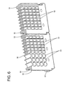
- FIG. 6 is a perspective view with a horizontal section showing an essential portion when the two adjacent rear holders are coupled,
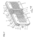
- FIG. 7 is a perspective view with a vertical section showing an essential portion when the two adjacent rear holders are coupled,
- FIG. 8 is an exploded side view in section of the auxiliary connector,
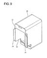
- FIG. 9 is a perspective view of a protection cap,
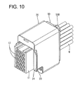
- FIG. 10 is a perspective view showing a state where the protection cap is mounted on the auxiliary connector,
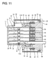
- FIG. 11 is a side view in section showing a state where the protection cap is mounted on the auxiliary connector,
- FIG. 12 is a perspective view of a mating connector,
- FIG. 13 is a schematic diagram showing a connected state of the two connectors.
- One preferred embodiment of the present invention is described with reference to FIGS. 1 to 13. A connector according to this embodiment is a (preferably watertight) female connector of the divided type connectable with a mating male connector, wherein one or more, preferably a plurality of (specifically, four)
auxiliary connectors 10 can be at least partly accommodated or selectively arrangeable into a frame or frame-like member 60. It should be noted that a side to be connected with the male connector is referred to as front side in the following description. - As shown in FIGS. 12 and 13, the mating male connector preferably is a connector for circuit board (printed circuit board), and one or more, preferably a plurality of male auxiliary connectors 90 (preferably of a plurality of sizes) are arranged or selectively arrangeable substantially side by side substantially in width direction WD and coupled or fixed to each other by a
coupling plate 93 arranged on a side thereof, preferably on the rear surfaces thereof as shown in FIG. 12. Eachauxiliary connector 90 includes areceptacle 91 preferably in the form of a substantially rectangular tube having an open front surface. Thereceptacles 91 adjacent to each other in width direction WD are at least partly partitioned bypartition walls 92. One or more maleterminal fittings 94 are mounted through the back walls of thereceptacles 91,
wherein front portions (preferably substantially front halves) of the maleterminal fittings 94 project into thereceptacles 91 and rear portions (preferably substantially rear halves) thereof are exposed from the rear surface of thecoupling plate 93 and preferably bent at an angle different from 0° or 180°, preferably substantially at right angles at one or more their intermediate positions so as to be connectable with conductor paths of the circuit board (not shown). Some of theauxiliary connectors 90 have respective cam pins 95 projecting from the lateral (upper) surfaces of thereceptacles 91. These cam pins 95 are or can be at least partly inserted intocam grooves 71 of a lever 70 (as a preferred movable member) mounted on or to theframe 60, and the two connectors are connected with each other as thelever 70 is operated (preferably rotated or pivoted). - One or more auxiliary connectors 10 (preferably of a plurality of sizes) are prepared so as to substantially correspond to the mating
auxiliary connectors 10, and eachauxiliary connector 10 includes aauxiliary housing 11, aretainer 35, preferably a sealingmember 40 and arear holder 50 as shown in FIG. 3. Theauxiliary housing 11 preferably is substantially in the form of a rectangular parallelepiped made e.g. of a synthetic resin, and one or more, preferably a plurality ofcavities 12 into which one or more respective female terminal fittings 30 (corresponding to preferred "terminal fittings") are at least partly insertable from an inserting side, preferably substantially from behind, are formed in theauxiliary housing 11. Thecavities 12 are arranged substantially in width direction WD at each of one or more stages, preferably at each of a plurality of stages defined one after another along height direction HD. One or more step-shapedengaging portions 13 engageable in a hooking manner with one ormore locking claws 51 A ofrespective locking legs 51 provided on therear holder 50 are formed on the lateral (upper) surface of theauxiliary housing 11. Further, one or more, preferably a pair of protectingwalls 14 for protecting the lockinglegs 51 stand or project at the (preferably substantially opposite) side(s) of the lateral (upper) surface of theauxiliary housing 11. The lockinglegs 51 preferably are arranged between theprotection walls 14, thereby being prevented from being turned up or deflected e.g. by getting caught by an external matter. - As shown in FIG. 8, an
insertion hole 15 for theretainer 35 is formed in the lateral (bottom) surface of eachauxiliary housing 11. Theinsertion hole 15 has such a depth as to communicate with or cross all thecavities 12, and the side-type retainer 35 is at least partly inserted thereinto from a retainer inserting side, preferably substantially from below. Theretainer 35 is made e.g. of a synthetic resin material and preferably substantially in the form of a flat plate as a whole, has terminal insertion holes 36 at positions substantially corresponding to thecavities 12, and has one or more, preferably a pair of (front and/or rear)resilient locking pieces 37 projecting from the lateral (upper) wall thereof preferably at the substantially opposite sides. A lockingprojection 38 is formed at a wall of eachterminal insertion hole 36, and theresilient locking pieces 37 are resiliently engageable with one or more retainer locking portions (not shown) formed in theinsertion hole 15 for theretainer 35. Theretainer 35 is displaceable between a partial locking position (as a preferred first position) and a full locking position (as a preferred second position), and is retained at these positions by the resilient engagement of theresilient locking pieces 37 with the retainer locking portions. When theretainer 35 is at the partial locking position, the lockingprojections 38 are substantially retracted from the correspondingcavities 12 to permit the insertion of the femaleterminal fittings 30. On the other hand, when theretainer 35 is pushed or moved from the partial locking position towards or to reach the full locking position, the lockingprojections 38 at least partly enter thecavities 12 to be located substantially opposite tojaw portions 31 at the rear ends of the femaleterminal fittings 30 substantially properly inserted into thecavities 12, thereby retaining the femaleterminal fittings 30. - As shown in FIG. 3, the one-
piece sealing member 40 made e.g. of a resilient material such as of a rubber material preferably is to be mounted on the rear surface of theauxiliary housing 11. This sealingmember 40 can be brought into contact with the (preferably substantially entire) rear surface of theauxiliary housing 11 and is formed with one or more wire insertion holes 41 at positions substantially corresponding to therespective cavities 12, and one or more wires W connected with the female terminal fittings 30 (preferably by crimping, soldering, insulation displacement or the like) can be passed through the respective wire insertion holes 41. Sealing is given between this sealingmember 40 and the wires W by bringing one or more, preferably a plurality of (three in the shown example)lips 43 formed at least partly on the inner circumferential surfaces of the wire insertion hoes 41 into hermetic or fluid- or watertight contact with the outer circumferential surfaces of the wires W while resiliently compressing them as shown in FIG. 11. The sealingmember 40 is also formed with one or more locking-leg insertion holes 42 at one or more (upper and/or lower) positions preferably with the respective wire insertion holes 41 located between these upper and lower positions, and the lockinglegs 51 can be inserted through the locking-leg insertion holes 42. One or more, preferably a plurality of (three in the shown example)lips 43 are also formed on the outer circumferential surface of the sealingmember 40. The sealingmember 40 comes into hermetic or fluid- or watertight contact with the surrounding wall of thereceptacle 91 while resiliently compressing thelips 43 when themating auxiliary connector 90 is fitted on or to the sealingmember 40, thereby providing sealing between themating auxiliary connector 90 and the sealingmember 40. - The
rear holder 50 for retaining or positioning the sealingmember 40 includes a holdermain body 52 made e.g. of a synthetic resin and preferably having the shape of a substantially rectangular block. The holdermain body 52 is formed with one or more, preferably a plurality ofinsertion paths 53 at positions substantially corresponding to the wire insertion holes 41 of the sealingmember 40, wherein theinsertion paths 53 are used to at least partly insert the femaleterminal fittings 30 and the wires W connected therewith into the wire insertion holes 41. Theinsertion paths 53 preferably have a diameter equal to or slightly larger thanbox portions 32 of the femaleterminal fittings 30, so that the wires W connected with the femaleterminal fittings 30 can be loosely insertable therethrough. One or more (preferably substantially plate-shaped) lockinglegs 51 project forward at one or more (upper and/or lower) positions of the holdermain body 52 preferably with therespective insertion paths 53 located between these upper and lower positions. The lockinglegs 51 preferably have such a length as to extend over the upper and bottom surfaces of theauxiliary housing 11 after passing through the locking-leg insertion holes 42 of the sealingmember 40 from behind, and the lockingclaws 51A formed at the leading ends of the lockinglegs 51 are or can be resiliently engaged with the engagingportions 13 of theauxiliary housing 11, whereby therear holder 50 is fixedly mounted on or to theauxiliary housing 11 with the sealingmember 40 squeezed or arranged or sandwiched between theauxiliary housing 11 and therear holder 50. In this embodiment, there are preparedrear holders 50 having up to three pairs of upper andlower locking legs 51 substantially in conformity with the sizes of the respectiveauxiliary housings 11. - The respective
rear holders 50 are coupled in an arranging direction AD (preferably substantially parallel to the width direction WD) preferably while the lateral edges thereof at least partly abut on each other. Thus, the respectiveauxiliary housings 11 are held united or integrally held substantially side by side by means of therear holders 50. More specifically, as shown in FIGS. 5 and 6, arecess 54 and aprojection 55 are provided in and/or on facing surfaces of tworear holders 50 adjacent to each other in the arranging direction AD, and theprojection 55 is (preferably resiliently) at least partly fitted into therecess 54 preferably by sliding the lateral edges of the two adjacentrear holders 50 along forward and backward directions FBD (being arranged at an angle different from 0° or 180°, preferably substantially normal to the arranging direction AD), thereby preventing therear holders 50 from being separated in forward and backward directions FBD. Apositioning piece 56 projects from one of the tworear holders 50 toward the other, and displacements of the tworear holders 50 on at least one of the directions along forward and backward directions FBD are prevented by the contact of thispositioning piece 56 with a stepped portion of the other rear holder when the coupling operation is completed. - As shown in FIG. 7, one or
more guide ribs 57 and one or more guide-rib receiving grooves 58 (corresponding to preferred "recess/projection engaging portions") engageable with each other are formed at one or more height positions preferably different from theaforementioned recess 54 andprojection 55 on the facing surfaces of the tworear holders 50 preferably substantially adjacent to each other in the arranging direction AD. Theguide ribs 57 preferably have a dovetail or undercut cross section and extend substantially in forward and backward directions FBD, and an assembling operation of therear holders 50 is substantially guided by relative sliding movements of theguide ribs 57 and the guide-rib receiving grooves 58. The preferably dovetail engagement of theguide ribs 57 and the guide-rib receiving grooves 58 prevents therear holders 50 from being separated along width direction WD (or arranging direction AD). By preferably differing the engaging height positions of theguide ribs 57 and the guide-rib receiving grooves 58 among the respectiverear holders 50, the tworear holders 50 conform and can be engaged in the case of a correct combination and do not conform and cannot be engaged in the case of a wrong combination. Such a construction for preventing an erroneous mounting of the tworear holders 50 is preferable. - One or more, preferably a pair of
guidable portions 59 preferably substantially in the form of rail grooves are so formed in one or more lateral surfaces, preferably in both upper and lower surfaces of the tworear holders 50 as to extend substantially in arranging direction AD (or in width direction WD) and make preferably openings in the opposite lateral surfaces of therear holders 50. One ormore guiding portions 65 formed in theframe 60 slide at least partly in or substantially along theguidable portions 59 to guide and insert therear holders 50 or theauxiliary connectors 10 into theframe 60 or substantially properly mount theauxiliary connectors 10 to theframe 60. - As shown in FIG. 4, preferably only one
lock portion 50B engageable with theframe 60 is formed on the lateral (upper) surface of therear holder 50 of theauxiliary connector 10 at least partly inserted last into the frame 60 (hereinafter, "lastauxiliary connector 10A). Thelock portion 50B projects on the lateral (upper) surface of acovering wall 59A for at least partly covering theguidable portion 59, and is resiliently engageable with an interlockingportion 61 formed in theframe 60 by a resilient deformation of the coveringwall 59A into theguidable portion 59. Further, the lastauxiliary connector 10A is formed with aprotection wall 50H projecting substantially forward from one lateral edge of therear holder 50. Thisprotection wall 50H is arranged to extend substantially along one lateral end surface of the sealingmember 40. More specifically, theprotection wall 50H preferably is formed into one closing plate standing over the entire length along height direction HD, and at least partly conceals an exposed end surface of the sealingmember 40 located in aninsertion opening 60A of theframe 60 when the lastauxiliary housing 11 is mounted into theframe 60. - The
frame 60 is similarly made e.g. of a synthetic resin and preferably substantially in the form of a flat framework, and has an open front surface and one open side surface as shown in FIGS. 1 and 2. The respectiveauxiliary connectors 10 can be successively mounted substantially along the arranging direction AD to or into theframe 60 through the open lateral (side) surface of theframe 60 as aninsertion opening 60A. One or more, preferably a pair of supportingshafts 62 for rotatably or pivotably supporting the lever 70 (as a preferred movable member) project from the lateral (upper and/or lower) walls of the frame 60 (or from one or more lateral walls where theauxiliary housings 10 are not to be inserted through). Thelever 70 preferably is gate-shaped as a whole by having anoperable portion 72 and a pair ofarm portions 73, and is so mounted as to straddle or bridge or span theframe 60 with botharm portions 73 supported on the supportingshafts 62. Thelever 70 is rotated or pivoted in an operating direction (e.g. counterclockwise) from a rotation starting position RSP shown in FIG. 1 to reach a rotation ending position, thereby coming into engagement with a side wall of theframe 60. Thearm portions 73 of thelever 70 are formed with the one ormore cam grooves 71 engageable with the cam pins 95 of the matingauxiliary connectors 10. - When the mating
auxiliary connectors 90 are connected with the correspondingauxiliary connector 10 after theauxiliary connectors 10 are mounted to or into theframe 60 with thelever 70 located at the rotation starting position RSP, the cam pins 95 at least partly enter the entrances of thecam grooves 71 of thelever 70. If thelever 70 is operated (rotated or pivoted) towards or to the rotation ending position in this state, the cam pins 95 move along thecam grooves 71 to exhibit a cam action therebetween, with the result that the two connectors are pulled toward each other or their connection is assisted. One or more, preferably a pair ofopening preventing walls 63 are so provided on the lateral (upper and/or lower) walls of theframe 60 as to at least partly cover the outer sides of thearm portions 73, thereby preventing thearm portions 73 from being deformed away from each other upon connecting the two connectors. - The
frame 60 has oneconnector accommodating space 64 capable of at least partly accommodating the respectiveauxiliary connectors 10 preferably en bloc without being partitioned by partition walls, and one or more, preferably a pair of rail-shapedguiding portions 65 are provided on the inner surface(s) of the lateral (upper and/or lower) wall(s) as to substantially extend in arranging direction AD (or substantially in width direction WD). One or more, preferably a pair of receivingwalls 66 extending substantially in parallel with the guidingportions 65 behind the guidingportions 65 are formed on the inner surface(s) of the lateral (upper and/or lower) wall(s) of theframe 60. Further, (preferably substantially rectangular) interlockingportions 61 are so formed near theinsertion opening 60A as to penetrate the respective (upper and/or lower) wall(s) of theframe 60. In theframe 60, an area before the receivingwalls 66 serves as theconnector accommodating space 64 and an area therebehind serves as awire accommodating space 67 for at least partly accommodating the wires W drawn out through the rear surfaces of therear holders 50 preferably substantially en bloc. Theframe 60 preferably is also formed with arear wall 68 for bending and guiding the wires W drawn out from the respectiveauxiliary connectors 10 at an angle different from 0° or 180°, preferably substantially normal, preferably substantially toward the same side as theinsertion opening 60A. - The respective
auxiliary connectors 10 are slid into theframe 60 substantially in their arranging direction AD through theinsertion opening 60A while preferably being united with each other by means of therear holders 50. At this time, the one or moreguidable portions 59 and the one ormore guiding portions 65 are engaged substantially in forward and backward directions FBD, whereby the respectiveauxiliary connectors 10 are positioned with respect to forward and backward directions FBD in theframe 60. When the lastauxiliary connector 10A is mounted, thelock portion 50B of therear holder 50 thereof is resiliently at least partly fitted into the interlockingportion 61 of theframe 60, with the result that the respectiveauxiliary connectors 10 are positioned with respect to width direction WD (arranging direction AD) and are prevented from coming out of theinsertion opening 60A. In this case, the lateral edge of theauxiliary connector 10 preferably inserted first comes substantially into contact with theback wall 69 of theframe 60, thereby preventing any further insertion of theauxiliary connectors 10. Upon connecting theauxiliary connectors 10 with the matingauxiliary connectors 90, pressing forces act in connecting direction CD (or forward and backward directions FBD) of the matingauxiliary connectors 90. However, these pressing forces are substantially received by the receivingwalls 66 to hinder backward displacements of the respectiveauxiliary connectors 10. - The sealing
members 40 preferably are protected by one or more protection caps 20 at least until the respectiveauxiliary connectors 10 are united by means of therear holders 50. Eachprotection cap 20 is made e.g. of a synthetic resin, has such a tubular shape as to at least partly surround the side surfaces of the correspondingauxiliary housing 11 and has open front and rear surfaces as shown in FIGS. 9 and 10. Thisprotection cap 20 is to be mounted on theauxiliary connector 10 substantially from front, and one or more temporarily holdingclaws 21 formed at the rear end thereof are resiliently engaged with theguidable portions 59 in a hooking manner, whereby theprotection cap 20 is or can be temporarily held onto or positioned with respect to theauxiliary connector 10. The temporarily heldprotection cap 20 is to be arranged to at least partly surround the correspondingauxiliary housing 11 and sealingmember 40 while defining clearances thereto. A hangingwall 22 that can be substantially opposed to the locking-leg projection walls 14 standing on theauxiliary housing 11 is formed at the front upper part of theprotection cap 20. Aretainer insertion opening 23 used to pass theretainer 35 into theinsertion hole 15 is formed in the lateral (bottom) surface of eachprotection cap 20 at a position substantially corresponding to theinsertion hole 15 for theretainer 35. - Such a
protection cap 20 preferably is to be mounted onto the correspondingauxiliary connector 10 from front before the femaleterminal fittings 30 are mounted into theauxiliary housing 11. Theprotection cap 20 is pulled forward after the femaleterminal fittings 30 are mounted and theretainer 35 is mounted, preferably thereby forcibly disengaging the temporarily holdingclaws 21 from theguidable portions 59 to detach theprotection cap 20 from theauxiliary connector 10. Upon pulling theprotection cap 20, one ormore flange portions 24 formed to bulge out sideways from the opposite lateral edges of the opening of theprotection cap 20 are or can be gripped or manipulated. - Next, a procedure of assembling this embodiment is described. First, the sealing
member 40 is attached or mounted to the rear surface of eachauxiliary housing 11, and therear holder 50 is mounted in this state by passing the one ormore locking legs 51 of therear holder 50 through the respective locking-leg insertion holes 42 of the sealingmember 40. The one ormore locking claws 51 A of therespective locking legs 51 are resiliently engaged with the corresponding engagingportions 13 of theauxiliary housing 11, whereby therear holder 50 is mounted on or to theauxiliary housing 11 with the sealingmember 40 substantially therebetween. - Subsequently, the
protection cap 20 preferably is mounted or slid substantially from front to resiliently and temporarily fit the one or more temporarily holdingclaws 21 of theprotection cap 20 into theguidable portion 59, thereby substantially protecting the sealingmember 40. The respectiveauxiliary connectors 10 are shipped with the sealingmembers 40 protected by the protection caps 20 to a harness assembling site. At the assembling site, theretainer 35 is first at least partly inserted into theauxiliary housing 11 from the retainer inserting side, preferably substantially from below, through theretainer insertion opening 23 of theprotection cap 20 to hold or position theretainer 35 at the partial locking position (first position). In this state, the one or more femaleterminal fittings 30 connected with the wires W are at least partly inserted from the inserting side, preferably substantially from behind, into the one or morerespective cavities 12 of theauxiliary housing 11 after being successively passed through therespective insertion paths 53 of therear holder 50 and the respective wire insertion holes 41 of the sealingmember 40, and are partly locked by lockingportions 18 resiliently deformably formed at the inner surfaces of thecavities 12. Thereafter, as shown in FIG. 11, theretainer 35 is inserted deeper towards or to substantially reach the full locking position (second position), thereby fully (or preferably doubly) locking the femaleterminal fittings 30 by the lockingprojections 38 of theretainer 35 to securely retain the femaleterminal fittings 30. Subsequently, the temporarily held state by theguidable portions 59 and the temporarily holdingclaws 21 is canceled preferably by pulling theprotection cap 20 forward by gripping or manipulating theflange portions 24, whereby theprotection cap 20 is or can be detached from theauxiliary connector 10. - After the mounting operation of the female
terminal fittings 30 is completed for all theauxiliary connectors 10, two adjacentrear holders 50 preferably are slid into engagement substantially in forward and backward directions FBD while the one ormore guide ribs 57 and the one or more guide-rib receiving grooves 58 are engaged with each other, and further coupled in such a manner as to prevent the separation thereof preferably by the resilient engagement of therecess 54 and theprojection 55. After one pair ofauxiliary connectors 10 are united in this way, therear holder 50 of anotherauxiliary housing 10 is coupled to one of the tworear holders 50. In this way, the respectiveauxiliary connectors 10 are successively united or integrally coupled substantially in the arranging direction AD. In this embodiment, fourauxiliary connectors 10 are united (assembled), wherein the lastauxiliary connector 10A is located at the right end. In such a united state, theguidable portions 59 of the respectiveauxiliary connectors 10 are substantially continuous on a substantially straight line along width direction WD (arranging direction AD) preferably substantially without any discontinuity. Any smaller discontinuity may be accommodated or substantially corrected by the interaction of the one or moreguidable portions 59 of theauxiliary connector 10 and the one or more respective guidingportions 65 of theframe 60. - Subsequently, the respective
auxiliary connectors 10 united in this manner are at least partly inserted into theconnector accommodating space 64 of theframe 60 through theinsertion opening 60A. Theguidable portions 59 of theauxiliary connector 10 at the one (left) end are at least partly fitted to the guidingportions 65 of theframe 60 at the start of the inserting operation, and the respectiveauxiliary connectors 10 are pushed toward the back side of theconnector accommodating space 64 in this state. Then, the respectiveauxiliary connectors 10 are at least partly inserted into theframe 60 while being guided by the guidingportions 65, and thelock portion 50B provided on the lastauxiliary housing 10A is resiliently engaged with the interlockingportion 61 of theframe 60 as the respectiveauxiliary connectors 10 reach substantially proper mount positions. When the respectiveauxiliary connectors 10 are substantially properly mounted, the sealingmember 40 of the lastauxiliary connector 10A is located at a position substantially facing theinsertion opening 60A of theframe 60, wherein the exposed end surface thereof is at least partly concealed by theprotection wall 50H of therear holder 50H to protect the sealingmember 40 e.g. from external matters (see FIG. 2). The respectiveauxiliary connectors 10 are held positioned relative to theframe 60 with intervals therebetween preferably held substantially constant by therear holders 50. Further, the wires W drawn out from the respectiveauxiliary connectors 10 preferably are at least partly bundled, at least partly accommodated in thewire accommodating space 67, and pulled out in a specified (predetermined or predeterminable) direction. - When the assembling is completed in this way, the mating
auxiliary connectors 90 are loosely fitted to theauxiliary connectors 10 and thelever 70 is operated (preferably rotated or pivoted) in this state, thereby preferably connectingauxiliary connectors partition walls 92 of the matingauxiliary connectors 90 slidably at least partly enter clearances between the facing surfaces of the adjacentrear holders 50 and theauxiliary connectors auxiliary connectors members 40 are resiliently compressed substantially in forward and backward directions FBD by connection compressing forces acting between the matingauxiliary connectors 90 and the receivingwalls 66, whereby the wire insertion holes 41 are deformed to narrow their diameters to come into close contact with the outer circumferential surfaces of the wires W. As a result, secure sealing can be provided between the sealingmembers 40 and the wires W. Further, when theauxiliary connectors receptacles 91 are closely fitted onto the sealingmembers 40, whereby thelips 43 of the sealingmembers 40 are squeezed by at least part of the surrounding walls of thereceptacles 91. As a result, secure sealing can be provided between the sealingmembers 40 and the matingauxiliary connectors 90. - As described above, since the partition walls of the frame between the
auxiliary connectors 10 adjacent in the arranging direction AD are or can be dispensed with according to this embodiment, the connector can be made smaller by as much as a total thickness of the partition walls. By inserting the respectiveauxiliary connectors 10 united by therear holders 50 into theframe 60 in the arranging direction AD, the relative positions of theauxiliary connectors 10 with respect to theframe 60 are determined. Thus, the respectiveauxiliary connectors 10 can be substantially positioned in theframe 60 even without the partition walls. If coupling structures are provided between theauxiliary connectors 10 in this case, sealing performances of the sealingmembers 40 cannot be obtained. However, according to this embodiment, specified sealing performances can be given by the sealingmembers 40 since the respectiveauxiliary connectors 10 are united utilizing therear holders 50. - Further, since the respective
auxiliary connectors 10 united or coupled or integrally assembled by the one or morerear holders 50 are at least partly inserted into theframe 60, assembling operability is better. Furthermore, since a plurality ofrear holders 50 preferably are provided in one-to-one correspondence with the respectiveauxiliary connectors 10 and can be coupled to each other in the arranging direction, the operation of inserting the femaleterminal fittings 30 can be performed for eachauxiliary connector 10. As a result, it is unlikely to occur to erroneously insert the femaleterminal fittings 30 and it becomes easier to handle the wires W, thereby making assembling operability even better. - Before the start of the connection with the mating connectors, the one or
more sealing members 40 preferably are constantly protected by the protection caps 20 and theprotection wall 50H. Thus, specified sealing performance can be securely exhibited. Since theprotection cap 20 is mounted utilizing theguidable portions 59 in this case, it is not necessary to provide a special construction for mounting theprotection cap 20 on theauxiliary connector 10. - Further, since the
partition walls 92 of the matingauxiliary connectors 90 slidably at least partly enter the clearances between the facing surfaces of theauxiliary connectors 10 adjacent to each other in the arranging direction AD when the matingauxiliary connectors 90 are connected with theauxiliary connectors 10, the forcible connection of theauxiliary connectors - Furthermore, the sealing
members 40 preferably come to possess a function of providing sealing between the matingauxiliary connectors 90 and the sealingmembers 40 in addition to a function of providing sealing between the wires W connected with the femaleterminal fittings 30 and the sealingmembers 40 after the connection with the mating connectors. Thus, it is not necessary to provide oneauxiliary connector 10 with a plurality of kinds of sealingmembers 40, thereby reducing the number of parts. - Accordingly, to miniaturize a connector one or more auxiliary connectors 10 (preferably of a plurality of sizes) are prepared. Each
auxiliary connector 10 includes anauxiliary housing 11, preferably a sealingmember 40 attached to the rear surface of theauxiliary housing 11, and at least onerear holder 50 mounted on the rear surface of the sealingmember 40 to preferably retain the sealingmember 40. Twoauxiliary connectors 10 adjacent to each other in an arranging direction AD are united with each other preferably by means of therear holders 50. The respective unitedauxiliary connectors 10 are at least partly inserted into aframe 60 in the arranging direction AD through aninsertion opening 60A of theframe 60, and are retained in theframe 60 by the resilient engagement of alock portion 50B provided preferably on the lastauxiliary connector 10A and an interlockingportion 61 of theframe 60. Since partition walls between the respectiveauxiliary connectors 10 are preferably deleted or omitted from theframe 60, the connector can be narrowed by as much as a total thickness of the partition walls. - The present invention is not limited to the above described and illustrated embodiment. For example, the following embodiments are also embraced by the technical scope of the present invention as defined by the claims. Beside the following embodiments, various changes can be made without departing from the scope and spirit of the present invention as defined by the claims.
- (1) Although the respective auxiliary connectors are at least partly inserted into the frame after being united by the rear holders in the foregoing embodiment, they may be at least partly inserted into or mounted to the frame individually or in smaller groups through the insertion opening and may be united in the frame. In short, it is sufficient to be able to at least partly accommodate the respective auxiliary connectors while determining the positions thereof relative to the frame even if there are no partition walls.
- (2) Although the rear holder is provided for each auxiliary connector in the foregoing embodiment, one rear holder may be provided for all or some of auxiliary connectors according to the present invention.
- (3) Although the lock portion engageable with the frame is provided only on the last auxiliary connector in the foregoing embodiment, it may be provided on each auxiliary connector according to the present invention.
- (4) Although the protection caps are kept mounted on the auxiliary connectors also during the operation of mounting the female terminal fittings in the foregoing embodiment, they may be detached from the auxiliary connectors before starting the operation of mounting the female terminal fittings according to the present invention.
- (5) The present invention is also applicable to a male connector in which a plurality of auxiliary connectors having the male terminal fittings mounted therein are accommodated in a frame.
- (6) The present invention is also applicable to nonwatertight connectors. In such a case, means for positioning auxiliary connectors relative to a frame may be provided on the auxiliary housings.
- (7) The present invention is also applicable to connectors being connectable to each other without the assistance of a lever displaying a cam action.
- (8) Even though in the above embodiment the auxiliary connectors are inserted into the frame through one single opening provided in the side surface, it should be understood that the auxiliary connectors may be at least partly inserted into one, two or more (preferably separate) openings provided in the side surface and/or back surface and/or front surface of the frame.
- (9) Even though in the above embodiment a rotatable or pivotable lever displaying a cam action is described as the preferred operable member, it should be understood that other operable members displaying a cam action such as sliders having a different operation path such as a substantially linear operation path may be used to connect the connectors or to assist their connection.
-
- 10 ...
- auxiliary connector
- 10A ...
- last auxiliary connector
- 11 ...
- auxiliary housing
- 20 ...
- protection cap
- 21 ...
- temporarily holding claws (mounting portion)
- 23 ...
- retainer insertion opening
- 30 ...
- female terminal fitting (terminal fitting)
- 35 ...
- retainer
- 40 ...
- sealing member
- 50 ...
- rear holder
- 50B ...
- lock portion
- 50H ...
- protection wall
- 57 ...
- guide rib (recess/projection engaging portions)
- 58 ...
- guide-rib receiving groove (recess/projection engaging portions)
- 59 ...
- guidable portion
- 60 ...
- frame
- 60A ...
- opening
- 61 ...
- interlocking portion
- 64 ...
- connector accommodating space
- 65 ...
- guiding portion
- 66 ...
- receiving wall
- 69 ...
- back wall of the frame
- 70 ...
- lever (operable member)
- 71 ...
- cam groove
- 73 ...
- arm portion
- 90 ...
- mating auxiliary connector (mating connector)
- 91 ...
- receptacle
- 92 ...
- partition wall
- W ...
- wire
Claims (15)
- A connector, comprising:a plurality of auxiliary connectors (10) in which one or more terminal fittings (30) can be at least partly accommodated, anda frame (60) in which the respective auxiliary connectors (10) can be at least partly accommodated en bloc,wherein the respective auxiliary connectors (10) are inserted into the frame (60) substantially in an arranging direction (AD) through an opening (60A) formed in one side surface of the frame (60), and wherein the auxiliary connectors (10) and/or the frame (60) comprise one or more positioning means (50; 59, 65) for determining the positions of the auxiliary connectors (10) relative to the frame (60).
- A connector according to claim 1, wherein a partition wall (92) of one or more mating auxiliary connectors (90) slidably is to at least partly enter a clearance between facing surfaces of two auxiliary connectors (10) adjacent to each other in the arranging direction (AD) when the two auxiliary connectors (10) are connected with the mating auxiliary connectors (90).
- A connector according to one or more of the preceding claims, wherein at least one sealing member (40) for providing sealing around one or more wires (W) connected with terminal fittings (30) is arranged at a rear part of the respective auxiliary connectors (10).
- A connector according to claim 3 in combination with claim 2, wherein a wall portion (91) of the mating auxiliary connector (90) is to be hermetically brought into close contact with a corresponding portion of the sealing member (40), preferably the outer circumferential surface thereof.
- A connector according to claim3 or 4, wherein at least one rear holder (50) for retaining the sealing member (40) is assembled at a rear part of the respective auxiliary connectors (10).
- A connector according to one or more of the preceding claims, wherein the respective auxiliary connectors (10) are united substantially in the arranging direction (AD) by means of at least one rear holder (50) and at least partly accommodated into the frame (60) in a united state, thereby constructing the positioning means (50).
- A connector according to claim 5 or 6, wherein a plurality of rear holders (50) are provided in one-to-one correspondence with the respective auxiliary connectors (10) and can be coupled to each other substantially in the arranging direction (AD).
- A connector according to claim 7, wherein:recess/projection engaging portions (57, 58) are provided on substantially facing surfaces of two rear holders (10) adjacent to each other in the arranging direction (AD), andthe recess/projection engaging portions (57, 58) preferably are to be engaged to permit an assembling operation of the two rear holders (50) when the two rear holders (50) are arranged in a correct combination, and preferably cannot be engaged to hinder the assembling operation of the two rear holders (50) when the two rear holders (50) are arranged in a wrong combination.
- A connector according to any one of claims 5 to 8, wherein the rear holder (50) is formed with at least one protection wall (50H) for at least partly concealing an exposed end surface of the sealing member (40) substantially facing the insertion opening (60A) at the auxiliary connector (10A) inserted last into the frame (60).
- A connector according to any one of claims 3 to 9, wherein at least one protection cap (20) at least partly surrounding the sealing member (40) while defining a clearance thereto is detachably mountable on the respective auxiliary connectors (10).
- A connector according to one or more of the preceding claims, wherein:a retainer (35) for retaining the substantially properly inserted terminal fittings (30) by being engaged with the terminal fittings (30) is assembled into at least part of the auxiliary connectors (10), andthe protection cap (20) preferably is formed with one or more retainer insertion openings (23) for permitting the at least partial insertion of the retainers (35) into the respective auxiliary connectors (10).
- A connector according to one or more of the preceding claims, wherein:each auxiliary connector (10) is formed with at least one guidable portion (59) that can be brought into sliding contact with at least one guiding portion (65) of the frame (60) when the auxiliary connector (10) is mounted into the frame (60), andthe protection cap preferably is formed with at least one mounting portion (21) detachably engageable with the guidable portion (59) before the respective auxiliary connectors (10) are mounted into the frame (60).
- A connector, in particular according to one or more of the preceding claims, comprising:a plurality of auxiliary connectors (10) in which one or more terminal fittings (30) can be at least partly accommodated, anda frame (60) in which the respective auxiliary connectors (10) can be at least partly accommodated en bloc,wherein a partition wall (92) of one or more mating auxiliary connectors (90) slidably is to at least partly enter a clearance between facing surfaces of two auxiliary connectors (10) adjacent to each other in the arranging direction (AD) when the two auxiliary connectors (10) are connected with the mating auxiliary connectors (90).
- A connector assembly method for assembling a connector, comprising the following steps:providing a plurality of auxiliary connectors (10) into which one or more terminal fittings (30) are at least partly accommodated,at least partly accommodating the respective auxiliary connectors (10) in a frame (60) en bloc by inserting the respective auxiliary connectors (10) into the frame (60) substantially in an arranging direction (AD) through an opening (60A) formed in one side surface of the frame (60), andpositioning the auxiliary connectors (10) relative to the frame (60) by means of one or more positioning means (50; 59, 65) provided on the auxiliary connectors (10) and/or the frame (60).
- A connector assembly method according to claim 14, further comprising the following steps:providing one or more mating auxiliary connectors (90), andconnecting at least two auxiliary connectors (10) with the mating auxiliary connectors (90) thereby slidably at least partly inserting a partition wall (92) of one or more mating auxiliary connectors (90) into a clearance between facing surfaces of two auxiliary connectors (10) adjacent to each other in the arranging direction (AD).
Applications Claiming Priority (1)
| Application Number | Priority Date | Filing Date | Title |
|---|---|---|---|
| JP2005180704A JP4591228B2 (en) | 2005-06-21 | 2005-06-21 | connector |
Publications (2)
| Publication Number | Publication Date |
|---|---|
| EP1737078A1 true EP1737078A1 (en) | 2006-12-27 |
| EP1737078B1 EP1737078B1 (en) | 2009-01-28 |
Family
ID=36923817
Family Applications (1)
| Application Number | Title | Priority Date | Filing Date |
|---|---|---|---|
| EP06011548A Expired - Lifetime EP1737078B1 (en) | 2005-06-21 | 2006-06-02 | A connector and a connector assembly method |
Country Status (4)
| Country | Link |
|---|---|
| US (1) | US7347744B2 (en) |
| EP (1) | EP1737078B1 (en) |
| JP (1) | JP4591228B2 (en) |
| DE (1) | DE602006005024D1 (en) |
Cited By (10)
| Publication number | Priority date | Publication date | Assignee | Title |
|---|---|---|---|---|
| WO2008137286A1 (en) * | 2007-05-03 | 2008-11-13 | Deringer-Ney, Inc. | Electrical connection apparatus |
| US7942686B2 (en) | 2007-05-03 | 2011-05-17 | Deringer-Ney, Inc. | Electrical barrier and moisture seal for an implanted medical device |
| US8187015B2 (en) | 2007-05-03 | 2012-05-29 | Deringer-Ney, Inc. | Electrical connection apparatus |
| US8251731B2 (en) | 2009-09-15 | 2012-08-28 | Deringer-Ney, Inc. | Electrical connection system and method for implantable medical devices |
| CN103493308A (en) * | 2011-04-18 | 2014-01-01 | 株式会社自动网络技术研究所 | Connector |
| EP2696445A1 (en) * | 2012-08-06 | 2014-02-12 | Hirschmann Automotive GmbH | Connector for a seat joint in an automobile |
| WO2014184283A1 (en) * | 2013-05-17 | 2014-11-20 | Delphi International Operations Luxembourg S.À R.L. | Connector for motor vehicles |
| EP2806506A1 (en) * | 2013-05-23 | 2014-11-26 | Phoenix Contact GmbH & Co. KG | Cover to be arranged on a multi-pin connector element |
| DE102007037177B4 (en) * | 2007-08-07 | 2015-02-26 | Tyco Electronics Amp Gmbh | Arrangement with contact modules and electrical plug element and set of contact modules |
| EP2961001A1 (en) * | 2014-06-25 | 2015-12-30 | Tyco Electronics AMP Korea Ltd. | Header assembly and connector for vehicle having the header assembly |
Families Citing this family (36)
| Publication number | Priority date | Publication date | Assignee | Title |
|---|---|---|---|---|
| JP4800904B2 (en) * | 2006-02-22 | 2011-10-26 | 矢崎総業株式会社 | connector |
| JP4252603B2 (en) * | 2007-01-31 | 2009-04-08 | タイコエレクトロニクスアンプ株式会社 | Electrical connector |
| JP4956323B2 (en) * | 2007-08-10 | 2012-06-20 | 古河電気工業株式会社 | Multipolar connector and method of assembling the same |
| JP5125407B2 (en) * | 2007-10-26 | 2013-01-23 | 住友電装株式会社 | connector |
| JP5233814B2 (en) * | 2009-04-20 | 2013-07-10 | 住友電装株式会社 | Sub-connector with protective cap for split connector and manufacturing method of split connector |
| MX2010006630A (en) * | 2009-06-15 | 2011-03-24 | R Byrne Norman | Power and data adapter assembly. |
| US8512079B2 (en) * | 2009-09-17 | 2013-08-20 | Henge Docks Llc | Docking station for an electronic device with improved electrical interface |
| JP5091983B2 (en) * | 2010-06-16 | 2012-12-05 | 矢崎総業株式会社 | Lever fitting type connector |
| CN102315551A (en) * | 2010-07-08 | 2012-01-11 | 胡连精密股份有限公司 | electrical connector |
| CA2893900C (en) | 2010-07-09 | 2017-10-24 | Norman R. Byrne | Power data housing |
| JP2013137922A (en) * | 2011-12-28 | 2013-07-11 | Tyco Electronics Japan Kk | Electric connector |
| US9276345B2 (en) * | 2012-03-16 | 2016-03-01 | Delphi International Operations Luxembourg S.A.R.L. | Electrical connector |
| JP5880381B2 (en) * | 2012-10-02 | 2016-03-09 | 住友電装株式会社 | connector |
| US9142916B2 (en) * | 2013-03-15 | 2015-09-22 | Tyco Electronics Corporation | Connector assembly with receptacle carriers |
| US9246317B2 (en) * | 2013-04-02 | 2016-01-26 | Norman R. Byrne | Electrical receptacle with frames for mounting in a support |
| MX349164B (en) * | 2013-06-03 | 2017-07-17 | Norman R Byrne | Low voltage power receptacle. |
| EP2854229B1 (en) * | 2013-09-25 | 2019-01-16 | Yazaki Europe Ltd | Connector and method for its assembling |
| US9246286B2 (en) * | 2013-09-25 | 2016-01-26 | Virginia Panel Corporation | High speed data module for high life cycle interconnect device |
| US9618968B2 (en) * | 2013-10-31 | 2017-04-11 | Sony Corporation | Mobile computing device with a combined housing and connector port |
| DE102014102171B4 (en) * | 2014-02-20 | 2015-10-29 | Harting Electric Gmbh & Co. Kg | contact support |
| JP6112423B2 (en) * | 2014-04-01 | 2017-04-12 | 住友電装株式会社 | Connector and connector fixing structure for wire harness |
| JP6604512B2 (en) * | 2016-02-24 | 2019-11-13 | 住友電装株式会社 | connector |
| CN110651401B (en) * | 2017-05-12 | 2021-10-22 | 哈廷电子有限公司及两合公司 | plug-in connector module |
| JP6816668B2 (en) * | 2017-07-11 | 2021-01-20 | 株式会社オートネットワーク技術研究所 | connector |
| US10116078B1 (en) * | 2017-08-01 | 2018-10-30 | Delphi Technologies, Inc. | High current compression blade connection system |
| EP3766142A4 (en) * | 2018-03-16 | 2021-12-08 | Molex, LLC | Sealed electrical connector system |
| US10903593B2 (en) * | 2019-05-14 | 2021-01-26 | International Business Machines Corporation | Off the module cable assembly |
| DE102019126469B4 (en) * | 2019-10-01 | 2021-08-05 | Lisa Dräxlmaier GmbH | CONNECTORS FOR THE MODULAR ARRANGEMENT OF CONTACT INSERTS AND THE USE AND METHOD OF MANUFACTURING |
| KR20230024332A (en) * | 2020-06-18 | 2023-02-20 | 스타우블리 일렉트리컬 커넥털스 아게 | modular plug connector |
| JP7470289B2 (en) * | 2020-08-27 | 2024-04-18 | 住友電装株式会社 | connector |
| JP7321209B2 (en) * | 2021-05-13 | 2023-08-04 | 矢崎総業株式会社 | Protector, wire harness, and wire harness assembly method |
| US12471232B2 (en) | 2022-08-04 | 2025-11-11 | Norman R. Byrne | Electrical power unit with replaceable outer cover |
| CN117638559A (en) | 2022-08-15 | 2024-03-01 | 莫仕连接器(成都)有限公司 | Electrical connection device |
| USD1099846S1 (en) * | 2022-09-09 | 2025-10-28 | Te Connectivity Brasil Indústria De Eletrônicos Ltda | Connector |
| DE102024116174B3 (en) * | 2024-06-10 | 2025-11-27 | Amphenol Fci Asia Pte Ltd | Modular connector |
| JP2026007869A (en) * | 2024-07-04 | 2026-01-19 | 株式会社オートネットワーク技術研究所 | Connector housing tool, vehicle, and method for housing connector |
Citations (5)
| Publication number | Priority date | Publication date | Assignee | Title |
|---|---|---|---|---|
| US5725397A (en) * | 1994-08-09 | 1998-03-10 | Sumitomo Wiring Systems, Ltd. | Divisional type connector |
| EP0940883A1 (en) * | 1998-03-04 | 1999-09-08 | Yazaki Corporation | Connector retaining construction |
| JP2000150058A (en) * | 1998-11-05 | 2000-05-30 | Sumitomo Wiring Syst Ltd | Waterproof connector |
| US6193550B1 (en) * | 1998-04-27 | 2001-02-27 | Yazaki Corporation | Coupling connector |
| US6332813B1 (en) * | 1999-08-02 | 2001-12-25 | Yazaki Corporation | Joining structure of connector |
Family Cites Families (6)
| Publication number | Priority date | Publication date | Assignee | Title |
|---|---|---|---|---|
| JPH0590841U (en) * | 1992-05-19 | 1993-12-10 | 住友電装株式会社 | connector |
| JP2002093515A (en) * | 2000-09-11 | 2002-03-29 | Yazaki Corp | Waterproof connector |
| JP3759870B2 (en) * | 2000-10-27 | 2006-03-29 | 住友電装株式会社 | connector |
| JP2002170622A (en) * | 2000-11-30 | 2002-06-14 | Sumitomo Wiring Syst Ltd | connector |
| US6514098B2 (en) * | 2000-12-28 | 2003-02-04 | Tyco Electronics Corporation | Electrical connector with terminal and connector position assurance devices |
| JP2004349072A (en) * | 2003-05-21 | 2004-12-09 | Yazaki Corp | Waterproof connector |
-
2005
- 2005-06-21 JP JP2005180704A patent/JP4591228B2/en not_active Expired - Fee Related
-
2006
- 2006-06-02 DE DE602006005024T patent/DE602006005024D1/en not_active Expired - Lifetime
- 2006-06-02 EP EP06011548A patent/EP1737078B1/en not_active Expired - Lifetime
- 2006-06-20 US US11/472,570 patent/US7347744B2/en not_active Expired - Fee Related
Patent Citations (5)
| Publication number | Priority date | Publication date | Assignee | Title |
|---|---|---|---|---|
| US5725397A (en) * | 1994-08-09 | 1998-03-10 | Sumitomo Wiring Systems, Ltd. | Divisional type connector |
| EP0940883A1 (en) * | 1998-03-04 | 1999-09-08 | Yazaki Corporation | Connector retaining construction |
| US6193550B1 (en) * | 1998-04-27 | 2001-02-27 | Yazaki Corporation | Coupling connector |
| JP2000150058A (en) * | 1998-11-05 | 2000-05-30 | Sumitomo Wiring Syst Ltd | Waterproof connector |
| US6332813B1 (en) * | 1999-08-02 | 2001-12-25 | Yazaki Corporation | Joining structure of connector |
Non-Patent Citations (1)
| Title |
|---|
| PATENT ABSTRACTS OF JAPAN vol. 2000, no. 08 6 October 2000 (2000-10-06) * |
Cited By (21)
| Publication number | Priority date | Publication date | Assignee | Title |
|---|---|---|---|---|
| US7690953B2 (en) | 2007-05-03 | 2010-04-06 | Deringer-Ney, Inc. | Stackable electrical connection apparatus |
| US7942686B2 (en) | 2007-05-03 | 2011-05-17 | Deringer-Ney, Inc. | Electrical barrier and moisture seal for an implanted medical device |
| US8187015B2 (en) | 2007-05-03 | 2012-05-29 | Deringer-Ney, Inc. | Electrical connection apparatus |
| US8206175B2 (en) | 2007-05-03 | 2012-06-26 | Deringer-Ney, Inc. | Visual indicator of proper interconnection for an implanted medical device |
| CN101689723B (en) * | 2007-05-03 | 2012-10-31 | 德林爵-内股份有限公司 | electrical connection device |
| WO2008137286A1 (en) * | 2007-05-03 | 2008-11-13 | Deringer-Ney, Inc. | Electrical connection apparatus |
| DE102007037177B4 (en) * | 2007-08-07 | 2015-02-26 | Tyco Electronics Amp Gmbh | Arrangement with contact modules and electrical plug element and set of contact modules |
| US8251731B2 (en) | 2009-09-15 | 2012-08-28 | Deringer-Ney, Inc. | Electrical connection system and method for implantable medical devices |
| EP2701241A4 (en) * | 2011-04-18 | 2015-01-07 | Autonetworks Technologies Ltd | CONNECTOR |
| CN103493308A (en) * | 2011-04-18 | 2014-01-01 | 株式会社自动网络技术研究所 | Connector |
| CN103493308B (en) * | 2011-04-18 | 2016-10-05 | 株式会社自动网络技术研究所 | Adapter |
| EP2696445A1 (en) * | 2012-08-06 | 2014-02-12 | Hirschmann Automotive GmbH | Connector for a seat joint in an automobile |
| FR3005796A1 (en) * | 2013-05-17 | 2014-11-21 | Delphi Int Operations Luxembourg Sarl | CONNECTOR FOR MOTOR VEHICLES |
| CN105393410A (en) * | 2013-05-17 | 2016-03-09 | 德尔福国际业务卢森堡公司 | Connector for motor vehicles |
| WO2014184283A1 (en) * | 2013-05-17 | 2014-11-20 | Delphi International Operations Luxembourg S.À R.L. | Connector for motor vehicles |
| CN105393410B (en) * | 2013-05-17 | 2018-07-03 | 德尔福国际业务卢森堡公司 | The connector of motor vehicle |
| CN104183969A (en) * | 2013-05-23 | 2014-12-03 | 菲尼克斯电气公司 | Protective cover |
| EP2806506A1 (en) * | 2013-05-23 | 2014-11-26 | Phoenix Contact GmbH & Co. KG | Cover to be arranged on a multi-pin connector element |
| EP2961001A1 (en) * | 2014-06-25 | 2015-12-30 | Tyco Electronics AMP Korea Ltd. | Header assembly and connector for vehicle having the header assembly |
| CN105305109A (en) * | 2014-06-25 | 2016-02-03 | 安普泰科电子韩国有限公司 | Head assembly and connector for a vehicle having the head assembly |
| CN105305109B (en) * | 2014-06-25 | 2019-09-10 | 安普泰科电子韩国有限公司 | Header assembly and connector for vehicle having the same |
Also Published As
| Publication number | Publication date |
|---|---|
| US20070004274A1 (en) | 2007-01-04 |
| JP2007005012A (en) | 2007-01-11 |
| US7347744B2 (en) | 2008-03-25 |
| EP1737078B1 (en) | 2009-01-28 |
| DE602006005024D1 (en) | 2009-03-19 |
| JP4591228B2 (en) | 2010-12-01 |
Similar Documents
| Publication | Publication Date | Title |
|---|---|---|
| EP1737078B1 (en) | A connector and a connector assembly method | |
| EP2075880B1 (en) | Lever-type connector, connector assembly and connecting method | |
| US7097503B2 (en) | Connector and a method of disassembling it | |
| US6659797B2 (en) | Connector with resiliently deflectable lock arm | |
| EP1962390B1 (en) | A connector and a connector assembly | |
| US20140242822A1 (en) | Connector and connector assembly provided therewith | |
| EP1672747A1 (en) | A connector | |
| US6616481B2 (en) | Connector | |
| US6568948B2 (en) | Connector | |
| US20140242819A1 (en) | Connector with force multiplying mechanism and connector assembly provided therewith | |
| EP1995826A1 (en) | A connector and a connector assembling method | |
| JP2000208195A (en) | connector | |
| JP2002305052A (en) | connector | |
| CN110581370B (en) | Terminals and Connectors | |
| EP1303009B1 (en) | A cover, a joint connector and a method for mounting a joint connector | |
| US6939163B2 (en) | Connector | |
| JP3800278B2 (en) | Structure for preventing misassembly of connector housing and cover | |
| US6547594B2 (en) | Connector | |
| US7114999B2 (en) | Connector and a connector assembly | |
| US6132252A (en) | Electrical connector with locking of the contact terminals | |
| EP1677392B1 (en) | A divided connector and method of assembling it | |
| JP2001351717A (en) | connector | |
| EP1801925B1 (en) | A connector | |
| US8337255B2 (en) | Connector and series of connectors | |
| JP4544065B2 (en) | connector |
Legal Events
| Date | Code | Title | Description |
|---|---|---|---|
| PUAI | Public reference made under article 153(3) epc to a published international application that has entered the european phase |
Free format text: ORIGINAL CODE: 0009012 |
|
| 17P | Request for examination filed |
Effective date: 20060614 |
|
| AK | Designated contracting states |
Kind code of ref document: A1 Designated state(s): AT BE BG CH CY CZ DE DK EE ES FI FR GB GR HU IE IS IT LI LT LU LV MC NL PL PT RO SE SI SK TR |
|
| AX | Request for extension of the european patent |
Extension state: AL BA HR MK YU |
|
| AKX | Designation fees paid |
Designated state(s): DE FR |
|
| GRAP | Despatch of communication of intention to grant a patent |
Free format text: ORIGINAL CODE: EPIDOSNIGR1 |
|
| RIN1 | Information on inventor provided before grant (corrected) |
Inventor name: TSUJI, TAKESHI Inventor name: MORIKAWA, SATOSHI Inventor name: TABATA, MASAAKI Inventor name: KOBAYASHI, TOMOHIKO Inventor name: NAKATA, TAKEHIRO |
|
| GRAS | Grant fee paid |
Free format text: ORIGINAL CODE: EPIDOSNIGR3 |
|
| GRAA | (expected) grant |
Free format text: ORIGINAL CODE: 0009210 |
|
| AK | Designated contracting states |
Kind code of ref document: B1 Designated state(s): DE FR |
|
| REF | Corresponds to: |
Ref document number: 602006005024 Country of ref document: DE Date of ref document: 20090319 Kind code of ref document: P |
|
| PLBE | No opposition filed within time limit |
Free format text: ORIGINAL CODE: 0009261 |
|
| STAA | Information on the status of an ep patent application or granted ep patent |
Free format text: STATUS: NO OPPOSITION FILED WITHIN TIME LIMIT |
|
| 26N | No opposition filed |
Effective date: 20091029 |
|
| REG | Reference to a national code |
Ref country code: FR Ref legal event code: ST Effective date: 20100226 |
|
| PG25 | Lapsed in a contracting state [announced via postgrant information from national office to epo] |
Ref country code: FR Free format text: LAPSE BECAUSE OF NON-PAYMENT OF DUE FEES Effective date: 20090630 |
|
| PGFP | Annual fee paid to national office [announced via postgrant information from national office to epo] |
Ref country code: DE Payment date: 20150527 Year of fee payment: 10 |
|
| REG | Reference to a national code |
Ref country code: DE Ref legal event code: R119 Ref document number: 602006005024 Country of ref document: DE |
|
| PG25 | Lapsed in a contracting state [announced via postgrant information from national office to epo] |
Ref country code: DE Free format text: LAPSE BECAUSE OF NON-PAYMENT OF DUE FEES Effective date: 20170103 |