EP1736836A1 - Belt cleaning device with means for changing the pressure between a cleaning roller and the belt - Google Patents
Belt cleaning device with means for changing the pressure between a cleaning roller and the belt Download PDFInfo
- Publication number
- EP1736836A1 EP1736836A1 EP06012553A EP06012553A EP1736836A1 EP 1736836 A1 EP1736836 A1 EP 1736836A1 EP 06012553 A EP06012553 A EP 06012553A EP 06012553 A EP06012553 A EP 06012553A EP 1736836 A1 EP1736836 A1 EP 1736836A1
- Authority
- EP
- European Patent Office
- Prior art keywords
- roller
- belt
- cleaning
- state
- backup
- Prior art date
- Legal status (The legal status is an assumption and is not a legal conclusion. Google has not performed a legal analysis and makes no representation as to the accuracy of the status listed.)
- Granted
Links
- 238000004140 cleaning Methods 0.000 title claims abstract description 228
- 229920001971 elastomer Polymers 0.000 claims description 11
- 239000006260 foam Substances 0.000 claims description 10
- 239000000806 elastomer Substances 0.000 claims description 9
- 230000004048 modification Effects 0.000 description 48
- 238000012986 modification Methods 0.000 description 48
- 238000003825 pressing Methods 0.000 description 43
- 238000000034 method Methods 0.000 description 30
- 238000010276 construction Methods 0.000 description 18
- 230000002093 peripheral effect Effects 0.000 description 17
- 238000000576 coating method Methods 0.000 description 8
- 239000000463 material Substances 0.000 description 8
- 239000011248 coating agent Substances 0.000 description 7
- 230000006835 compression Effects 0.000 description 7
- 238000007906 compression Methods 0.000 description 7
- 238000010586 diagram Methods 0.000 description 7
- 238000010438 heat treatment Methods 0.000 description 6
- 230000000694 effects Effects 0.000 description 5
- 229920003002 synthetic resin Polymers 0.000 description 5
- 239000000057 synthetic resin Substances 0.000 description 5
- 239000002184 metal Substances 0.000 description 4
- 229920000034 Plastomer Polymers 0.000 description 3
- 230000015572 biosynthetic process Effects 0.000 description 3
- 229920003051 synthetic elastomer Polymers 0.000 description 3
- 239000005061 synthetic rubber Substances 0.000 description 3
- 238000011144 upstream manufacturing Methods 0.000 description 3
- 239000004642 Polyimide Substances 0.000 description 2
- 230000002238 attenuated effect Effects 0.000 description 2
- 239000003795 chemical substances by application Substances 0.000 description 2
- 239000003086 colorant Substances 0.000 description 2
- 238000004891 communication Methods 0.000 description 2
- 239000000428 dust Substances 0.000 description 2
- 230000002708 enhancing effect Effects 0.000 description 2
- 229920000515 polycarbonate Polymers 0.000 description 2
- 239000004417 polycarbonate Substances 0.000 description 2
- 229920001721 polyimide Polymers 0.000 description 2
- 239000005060 rubber Substances 0.000 description 2
- 239000002699 waste material Substances 0.000 description 2
- 238000005452 bending Methods 0.000 description 1
- 239000006229 carbon black Substances 0.000 description 1
- 230000000593 degrading effect Effects 0.000 description 1
- 238000001514 detection method Methods 0.000 description 1
- 230000001627 detrimental effect Effects 0.000 description 1
- 238000007599 discharging Methods 0.000 description 1
- 230000005489 elastic deformation Effects 0.000 description 1
- NBVXSUQYWXRMNV-UHFFFAOYSA-N fluoromethane Chemical compound FC NBVXSUQYWXRMNV-UHFFFAOYSA-N 0.000 description 1
- 230000014509 gene expression Effects 0.000 description 1
- 229910052736 halogen Inorganic materials 0.000 description 1
- 150000002367 halogens Chemical class 0.000 description 1
- 230000001678 irradiating effect Effects 0.000 description 1
- 229920005989 resin Polymers 0.000 description 1
- 239000011347 resin Substances 0.000 description 1
- 229920002379 silicone rubber Polymers 0.000 description 1
Images



Classifications
-
- G—PHYSICS
- G03—PHOTOGRAPHY; CINEMATOGRAPHY; ANALOGOUS TECHNIQUES USING WAVES OTHER THAN OPTICAL WAVES; ELECTROGRAPHY; HOLOGRAPHY
- G03G—ELECTROGRAPHY; ELECTROPHOTOGRAPHY; MAGNETOGRAPHY
- G03G15/00—Apparatus for electrographic processes using a charge pattern
- G03G15/14—Apparatus for electrographic processes using a charge pattern for transferring a pattern to a second base
- G03G15/16—Apparatus for electrographic processes using a charge pattern for transferring a pattern to a second base of a toner pattern, e.g. a powder pattern, e.g. magnetic transfer
- G03G15/1605—Apparatus for electrographic processes using a charge pattern for transferring a pattern to a second base of a toner pattern, e.g. a powder pattern, e.g. magnetic transfer using at least one intermediate support
- G03G15/161—Apparatus for electrographic processes using a charge pattern for transferring a pattern to a second base of a toner pattern, e.g. a powder pattern, e.g. magnetic transfer using at least one intermediate support with means for handling the intermediate support, e.g. heating, cleaning, coating with a transfer agent
-
- G—PHYSICS
- G03—PHOTOGRAPHY; CINEMATOGRAPHY; ANALOGOUS TECHNIQUES USING WAVES OTHER THAN OPTICAL WAVES; ELECTROGRAPHY; HOLOGRAPHY
- G03G—ELECTROGRAPHY; ELECTROPHOTOGRAPHY; MAGNETOGRAPHY
- G03G21/00—Arrangements not provided for by groups G03G13/00 - G03G19/00, e.g. cleaning, elimination of residual charge
-
- G—PHYSICS
- G03—PHOTOGRAPHY; CINEMATOGRAPHY; ANALOGOUS TECHNIQUES USING WAVES OTHER THAN OPTICAL WAVES; ELECTROGRAPHY; HOLOGRAPHY
- G03G—ELECTROGRAPHY; ELECTROPHOTOGRAPHY; MAGNETOGRAPHY
- G03G2215/00—Apparatus for electrophotographic processes
- G03G2215/16—Transferring device, details
- G03G2215/1647—Cleaning of transfer member
- G03G2215/1661—Cleaning of transfer member of transfer belt
Definitions
- the disclosure relates to a belt cleaning device for cleaning a surface of a belt on which a conveying object is supported and conveyed.
- the disclosure also relates to an image forming apparatus for forming images with a developing agent such as toner.
- Image forming apparatuses employing a conveying belt that supports and conveys sheets of paper for image formation are well known in the art.
- One such image forming apparatus disclosed in U.S. Patent Application Publication No. 2004/253013 forms toner images on paper using a process unit for transferring the toner onto the paper as the paper is supported on a surface of the conveying belt and conveyed in a predetermined direction.
- the conveying belt is a seamless, endless belt.
- a plurality of the process units is arranged along the conveying direction of the belt with each process unit disposed in confrontation with the surface of the conveying belt.
- the process units accommodate toner in one of the colors cyan, magenta, yellow, and black to support multicolor image formation.
- the image forming apparatus disclosed in U.S. Patent Application Publication No. 2004/253013 performs a calibration process to correct problems in color registration.
- the image forming apparatus forms a toner pattern on the surface of the conveying belt and detects the density of the pattern using a sensor disposed in confrontation with the surface of the conveying belt.
- the image forming apparatus also has a cleaning unit disposed near the sensor and confronting the surface of the conveying belt for removing the toner pattern after calibration.
- the cleaning unit includes an electrostatic brush disposed in confrontation with the surface of the conveying belt and capable of applying a predetermined bias voltage, a secondary roller using electrostatic attraction to remove toner deposited on the electrostatic brush, and a waste toner box encompassing the electrostatic brush and secondary roller for collecting waste toner.
- the invention may provide a belt cleaning device for cleaning a surface of a belt that conveys a conveying object.
- the belt cleaning device includes a cleaning roller, a backup roller, and a roller-pressing-state setting mechanism.
- the cleaning roller is disposed in confrontation with the surface of the belt.
- the backup roller is disposed in confrontation with the cleaning roller with the belt interposed between the cleaning roller and the backup roller.
- the roller-pressing-state setting mechanism selectively sets a state of the backup roller to a first state in which the backup roller is pressed against the cleaning roller via the belt, allowing a first pressure to be applied between the cleaning roller and the surface of the belt, and a second state in which a second pressure is applied between the cleaning roller and the surface of the belt.
- the second pressure is less than the first pressure.
- the invention may also provide an image forming apparatus.
- the image forming apparatus includes an endless belt, a cleaning roller, a backup roller, and a roller-pressing-state setting mechanism.
- the endless belt has an outer surface.
- the endless belt conveys a conveying object on the outer surface.
- the cleaning roller is disposed in confrontation with the outer surface of the endless belt.
- the backup roller is disposed in confrontation with the cleaning roller with the endless belt interposed between the cleaning roller and the backup roller.
- the roller-pressing-state setting mechanism selectively sets a state of the backup roller to a first state in which the backup roller is pressed against the cleaning roller via the endless belt, allowing a first pressure to be applied between the cleaning roller and the outer surface of the endless belt, and a second state in which a second pressure is applied between the cleaning roller and the outer surface of the endless belt.
- the second pressure is less than the first pressure.
- Fig. 1 is a side cross-sectional view of a laser printer 1 according to illustrative aspects of the invention.
- the right side of the laser printer 1 in Fig. 1 will be referred to as the "front side,” while the left side will be referred to as the “rear side.”
- the expressions "front”, “rear”, “upper”, and “lower” are used to define the various parts when the laser printer 1 is disposed in an orientation in which it is intended to be used.
- the laser printer 1 includes a paper cassette 20, process cartridges 30, scanning units 40, a paper conveying unit 50, a transfer unit 60, a fixing unit 70, a discharge unit 80, and a control unit 90.
- the laser printer 1 also includes a main casing 12 that is shaped to cover a main frame (not shown).
- the main frame functions to support a driving force transmitting mechanism configured of motors and gears.
- a top cover 14 is mounted on the top of the main casing 12.
- the top cover 14 has ribs 14a extending downward from lower edges of the top cover 14 on the rear side thereof and having through-holes formed near the bottom ends thereof. Support shafts protruding from the main casing 12 at positions corresponding to the ribs 14a are inserted through the through-holes formed in the ribs 14a for pivotally supporting the top cover 14.
- the top cover 14 can pivotally move open and closed over the main casing 12 about the support shafts.
- a discharge opening 12a is formed in the upper rear section of the main casing 12 above the rear side of the top cover 14.
- a discharge tray 14b is also formed on the top surface of the top cover 14 for supporting sheet-like paper P discharged through the discharge opening 12a.
- the paper cassette 20 is detachably mounted in a lower section of the main casing 12.
- the paper cassette 20 is capable of accommodating a sheet-like paper P in a stacked state.
- the paper cassette 20 includes a cassette case 21 forming the outer casing thereof, and a paper-pressing plate 23 and a separating pad 25 disposed within the cassette case 21.
- the paper-pressing plate 23 is a plate-shaped member that functions to support a stack of paper.
- the paper-pressing plate 23 is pivotally supported about an end on the rear side (the end farthest from the separating pad 25 in Fig. 1).
- a spring (not shown) is disposed beneath the front end of the paper-pressing plate 23 (the end nearest the separating pad 25 in Fig. 1) for urging the front end upward.
- the separating pad 25 is disposed near the front end of the cassette case 21 and downstream of the paper-pressing plate 23 in a paper-conveying direction.
- a compression spring 27 is disposed beneath the separating pad 25 for urging the separating pad 25 upward.
- the top surface of the separating pad 25 (the surface over which the paper P is conveyed) is a separating surface configured of a material having a higher coefficient of friction with the paper P than the coefficient of friction between two sheets of paper P (such as felt or rubber).
- the separating pad 25 functions to separate the sheets of paper P so that the paper P is conveyed toward an image forming unit (process cartridges 30 and the like) in the main casing 12 for image formation one sheet at a time.
- a follow roller 29 is disposed in an upper end of the cassette case 21 on the front side thereof and at a position downstream of the separating pad 25 in the paper-conveying direction.
- the follow roller 29 rotates freely in the cassette case 21 and functions to guide sheets of the paper P separated by the separating pad 25 and conveyed one sheet at a time toward the image forming unit.
- a plurality of the process cartridges 30 (30Y, 30M, 30C, and 30K) constituting the image forming unit are detachably mounted in the main casing 12 above the paper cassette 20.
- the process cartridges 30Y, 30M, 30C, and 30K are arranged in the order given from the front side to the rear side of the laser printer 1 and accommodate toner of the colors yellow, magenta, cyan, and black, respectively.
- Each process cartridge 30 includes a cartridge case 31; and a photosensitive drum 32 on which latent images are formed, a developing roller 33 for bearing toner on the peripheral surface thereof to develop the latent images formed on the photosensitive drum 32, and a supply roller 34 for supplying toner to the peripheral surface of the developing roller 33, all of which are rotatably supported in the cartridge case 31.
- the photosensitive drum 32 is disposed in a longitudinal end of the cartridge case 31 (the bottom end in Fig. 1) so that a portion of the peripheral surface of the photosensitive drum 32 is exposed outside of the cartridge case 31 through an opening formed in the end of the cartridge case 31.
- the developing roller 33 is formed of a synthetic rubber material and is positioned so that the peripheral surface of the developing roller 33 contacts the photosensitive drum 32.
- the supply roller 34 is formed of a foam sponge material and contacts the developing roller 33 with pressure.
- the photosensitive drum 32, developing roller 33, and supply roller 34 are driven to rotate via the driving force transmitting mechanism provided in the main frame. Further, a predetermined developing bias voltage can be applied between the photosensitive drum 32 and developing roller 33.
- a charger 35 is disposed in confrontation with the peripheral surface of each photosensitive drum 32 at a position upstream of the area of contact between the photosensitive drum 32 and developing roller 33 with respect to the rotational direction of the photosensitive drum 32 (indicated by an arrow in Fig. 1).
- the charger 35 charges the peripheral surface of the photosensitive drum 32 with a uniform charge.
- the scanning units 40 are provided inside the main casing 12 for each of the process cartridges 30 for irradiating a laser beam on the respective photosensitive drums 32 (indicated by a single-dot chain line in Fig. 1).
- Each scanning unit 40 includes a scanner case 41, a polygon mirror 42a, a polygon motor 42b, a lens 43, and a reflecting mirror 44.
- the polygon motor 42b is fixed to the scanner case 41 and has a drive shaft for supporting the polygon mirror 42a.
- the polygon motor 42b is capable of driving the polygon mirror 42a to rotate at a predetermined rotational speed.
- a laser light emitting unit (not shown) generates a laser beam based on image data.
- the laser beam is deflected by the rotating polygon mirror 42a and scanned along a width direction of the paper.
- the lens 43 and reflecting mirror 44 are supported within the scanner case 41 and are aligned so that the laser beam deflected by the polygon mirror 42a is irradiated onto the peripheral surface of the photosensitive drum 32.
- the paper conveying unit 50 is disposed inside the main casing 12 for conveying the paper P toward the process cartridges 30.
- the paper conveying unit 50 includes a pickup roller 51, a feeding roller 52, a conveying roller 53, registration rollers 54, and a paper guide 55.
- the pickup roller 51 is rotatably supported on the main frame (not shown).
- the pickup roller 51 is driven to rotate via the driving force transmitting mechanism provided on the main frame.
- the pickup roller 51 contacts with a predetermined pressure the stack of paper P urged upward by the paper-pressing plate 23.
- the feeding roller 52 is also rotatably supported in the main frame and is configured to rotate via the driving force transmitting mechanism.
- the feeding roller 52 is disposed in confrontation with the separating pad 25 so that the peripheral surface of the feeding roller 52 contacts the separating pad 25 with a predetermined force.
- the conveying roller 53 is rotatably supported in the main frame and a position opposing the follow roller 29 and farther frontward than the separating pad 25 (downstream of the separating pad 25 in the rotational direction of the feeding roller 52).
- the conveying roller 53 is driven to rotate via the driving force transmitting mechanism.
- the registration rollers 54 are also rotated via the driving force transmitting mechanism and function to adjust the direction and conveying timing of the paper P.
- the paper guide 55 functions to receive the paper P conveyed by the registration rollers 54 and to guide the paper P toward the process cartridges 30.
- the transfer unit 60 is disposed inside the main casing 12 between the paper cassette 20 and the process cartridges 30.
- the transfer unit 60 includes a belt 61, transfer rollers 62, a drive roller 63, a support roller 64, a density-detecting unit 65, and a belt cleaner 66 serving as a belt cleaning device.
- the belt 61 is formed of a synthetic resin, such as polycarbonate or polyimide, or an elastomer such as synthetic rubber.
- the belt 61 is formed without seams and has a longitudinal direction along the paper-conveying direction.
- the belt 61 is formed slightly wider than the width of a maximum sized sheet of paper P that can be used in the laser printer 1. Hence, when a sheet of maximum size is supported on the surface of the belt 61, the surface of the belt 61 is exposed on the widthwise sides of the paper P.
- the width of the belt 61 corresponding to the width of a maximum sized sheet of paper P will be referred to as the "effective width.”
- the belt 61 is looped around the transfer rollers 62, drive roller 63, and support roller 64 when viewed from the side.
- the transfer rollers 62 are rotatably supported at positions confronting each of the photosensitive drums 32 provided in the process cartridges 30Y, 30M, 30C, and 30K, with the belt 61 interposed between the transfer rollers 62 and the photosensitive drums 32. Together with the process cartridges 30, the transfer rollers 62 constitute the image forming unit.
- a transfer bias voltage can be applied between the transfer rollers 62 and photosensitive drums 32 for transferring toner from the peripheral surface of the photosensitive drums 32 onto the surface of a sheet of paper P supported on the belt 61.
- the drive roller 63 and support roller 64 are rotatably supported on a transfer unit frame (not shown) at positions that stretch the belt 61 taut in the paper-conveying direction.
- the drive roller 63 is driven to rotate in a direction indicated by the arrow in Fig. 1 via the driving force transmitting mechanism in order to move the belt 61 circularly in the direction indicated by arrows in Fig. 1. More specifically, the drive roller 63 is disposed near the black process cartridge 30K, positioned farthest rearward of the process cartridges 30, while the support roller 64 is disposed near the yellow process cartridge 30Y, positioned farthest frontward of the process cartridges 30.
- the belt 61 is supported on the drive roller 63 and support roller 64 below the process cartridges 30 and can support a sheet of paper P on a top surface (an outer surface 61a shown in Figs. 2A and 2B) while moving along the array of photosensitive drums 32 provided in the process cartridges 30.
- the density-detecting unit 65 is disposed below the drive roller 63 and has a reflective density sensor 65a.
- the reflective density sensor 65a generates signals corresponding to the density of toner on the surface of the belt 61 based on the intensity of light emitted from a light-emitting unit and the intensity of light reflected off the surface of the belt 61 and detected by a light-receiving unit.
- the reflective density sensor 65a can generate a signal indicating the toner density of marks formed on the belt 61, such as a toner pattern formed for calibrating density or for adjusting color registration in the paper-conveying direction (hereinafter, both will be referred to as "image calibration").
- the belt cleaner 66 is disposed below the belt 61 and downstream of the density-detecting unit 65 with respect to the direction in which the belt moves on the lower side.
- the belt cleaner 66 is also positioned to confront the surface of the belt 61 in order to remove foreign matter that has deposited on the surface of the belt 61. A more detailed description of the belt cleaner 66 will be given later.
- the fixing unit 70 is disposed inside the main casing 12 and downstream of the transfer unit 60 in the paper-conveying direction.
- the fixing unit 70 functions to fix a toner image formed on the surface of the paper P to the paper P.
- the fixing unit 70 includes a heating roller 71 and a pressure roller 72.
- the heating roller 71 is configured of a metal cylinder whose surface has been treated by a release agent, and a halogen lamp accommodated inside the cylinder.
- the heating roller 71 is driven to rotate by the driving force transmitting mechanism.
- the pressure roller 72 is a roller formed of silicon rubber that is rotatably supported in confrontation with the heating roller 71.
- the pressure roller 72 presses against the heating roller 71 with a predetermined pressure and follows the rotation of the heating roller 71.
- the discharge unit 80 is disposed inside the main casing 12 in a rearmost section thereof for discharging the paper P out of the laser printer 1 after the paper P has passed through the fixing unit 70.
- the discharge unit 80 includes a paper guide 81, and a pair of discharge rollers 83.
- the discharge rollers 83 are disposed near the discharge opening 12a and are driven to rotate by the driving force transmitting mechanism.
- the paper guide 81 functions to guide the paper P having passed through the fixing unit 70 to the discharge rollers 83.
- the control unit 90 is accommodated in a lower section of the main casing 12.
- the control unit 90 is electrically connected to various motors provided on the main frame for driving various movable parts provided in the process cartridge 30 and paper conveying unit 50; actuators; sensors; the laser light emitting units and polygon motors 42b provided in the scanning units 40; and the like.
- the control unit 90 is capable of controlling the operations and timing of the process cartridge 30, scanning unit 40, paper conveying unit 50, transfer unit 60, fixing unit 70, and discharge unit 80.
- Figs. 2A and 2B are enlarged views of a region inside the laser printer 1 around the belt cleaner 66.
- Fig. 2C is a perspective view schematically showing a roller shaft holder 68b and a roller case 68c (described later) in the belt cleaner 66.
- the belt cleaner 66 is configured of a cleaning unit 67, and a backup unit 68 disposed so as to confront the cleaning unit 67 on the opposite side of the belt 61.
- the cleaning unit 67 is disposed on the underside of the outer surface 6 1 a of the belt 61 that supports the paper. Further, like the transfer rollers 62 shown in Fig. 1, the backup unit 68 in the illustrative aspects is also disposed in the space encompassed by the belt 61.
- the cleaning unit 67 is configured of a cleaning roller 67a, a secondary roller 67b, and a cleaning blade 67c.
- the belt 61 drops downward by its own weight.
- the cleaning roller 67a is positioned below the outer surface 61a of the belt 61 so that the outer surface 61a of the belt 61 is in constant contact with the cleaning roller 67a.
- the cleaning roller 67a in the illustrative aspects is configured of a main roller member formed around a metal rotational shaft.
- the main roller member is formed primarily of a synthetic rubber mixed with carbon black so as to have a semiconductive property (with a resistance of approximately 10 5 through 10 7 ohms).
- the rotational shaft of the cleaning roller 67a is connected to an output terminal of a high-voltage power supply.
- the power supply applies a predetermined cleaning bias voltage (such as -1.4 kV) between the cleaning roller 67a and the backup roller 68a, which is grounded.
- the secondary roller 67b is a metal roller member disposed diagonally below the cleaning roller 67a so as to contact the same.
- the secondary roller 67b is connected to an output terminal of a high-voltage power supply.
- the power supply applies a predetermined secondary cleaning bias voltage between the secondary roller 67b and the cleaning roller 67a.
- the predetermined secondary cleaning bias voltage is - 0.8 kV so that the potential of the secondary roller 67b with respect to ground potential is -2.2 kV.
- the cleaning roller 67a and secondary roller 67b are supported on the transfer unit frame mentioned above and can be driven to rotate in the direction of the arrows shown in Figs. 2A and 2B.
- the belt cleaner 66 of the illustrative aspects is configured so that the peripheral surface of the cleaning roller 67a where the cleaning roller 67a contacts the outer surface 61 a of the belt 61 (i.e., a tangent to the cleaning roller 67a at the position of contact) moves opposite (in a direction counter to) the moving direction of the belt 61 at the position of contact, as indicated by arrows in Figs. 2A and 2B.
- the belt cleaner 66 of the illustrative aspects is configured such that the cleaning roller 67a is driven to rotate in a counter direction to the moving direction of the belt 61.
- the rubber cleaning blade 67c is disposed in contact with the peripheral surface of the secondary roller 67b.
- the cleaning blade 67c contacts the peripheral surface of the secondary roller 67b in a direction counter to the rotation of the secondary roller 67b.
- the cleaning blade 67c has a base end 67c1 and a free end 67c2.
- the base end 67c1 of the cleaning blade 67c is supported on the transfer unit frame so that the free end 67c2 on the end opposite the base end 67c1 contacts the secondary roller 67b.
- the direction that the cleaning blade 67c extends from the base end 67c1 to the free end 67c2 is opposite, or counter to, the rotational direction of the secondary roller 67b at the point of contact with the free end 67c2.
- the cleaning blade 67c is in a substantially horizontal orientation at a position lower than the rotational axis of the secondary roller 67b so that the free end 67c2 contacts the peripheral surface of the secondary roller 67b downstream of the lowest point of the secondary roller 67b in the rotational direction of the same.
- the backup unit 68 can selectively set the position of the backup roller 68a between a separated position (a pressing release state shown in Fig. 2A) in which the backup roller 68a is separated a predetermined distance from the inner surface 61b of the belt 61, and a pressing position (a pressing state shown in Fig. 2B) in which the backup roller 68a presses against the cleaning roller 67a via the belt 61.
- the backup unit 68 includes the roller shaft holders 68b.
- the roller shaft holders 68b are provided on each end of the backup roller 68a.
- the roller shaft holders 68b are shaped substantially like rectangular parallelepipeds and have a through-hole formed substantially in the center when viewed from the side.
- a rotational shaft 68a1 is provided in the center of the backup roller 68a and protrudes from both ends thereof. The both ends of the rotational shaft 68a1 are rotatably inserted into the through-holes formed in the roller shaft holders 68b.
- the backup unit 68 also includes the roller case 68c that houses the backup roller 68a.
- the roller case 68c is substantially box-shaped and open on the bottom. A lower portion of the backup roller 68a is exposed at the bottom opening of the roller case 68c.
- Grooves 68c1 are formed in each side wall of the roller case 68c (walls on both ends of the roller case 68c with respect to the paper width direction). Each groove 68c1 extends substantially in a vertical direction. Each groove 68c1 accommodates the roller shaft holder 68b and is capable of guiding the roller shaft holder 68b in a substantially vertical direction.
- Compression springs 68d are configured of coil springs. Each compression spring 68d has a bottom end fixed to the top end of one of the roller shaft holders 68b and a top end fixed to an upper portion of the roller case 68c.
- the compression springs 68d function to press the backup roller 68a toward the belt 61 and cleaning roller 67a by urging the backup roller 68a downward via the roller shaft holders 68b such that the backup roller 68a is in contact with the inner surface 61 b of the belt 61.
- the top end of the roller case 68c is fixed to a bottom surface of a roller case holder 68e.
- the roller case holder 68e is a plate-shaped member having a pivot shaft 68e1 provided on one end thereof.
- the roller case holder 68e also has a free end 68e2 opposite the pivot shaft 68e1.
- the roller case holder 68e is supported on the transfer unit frame via the pivot shaft 68e1 so as to be capable of pivoting about the pivot shaft 68e1 for raising and lowering the free end 68e2 in a substantially vertical direction.
- a spring holder 68g formed of a plate-shaped member is supported on the transfer unit frame above the free end 68e2.
- a raising spring 68h configured of a coil spring (tension spring) is connected between the spring holder 68g and the free end 68e2 of the roller case holder 68e for urging the free end 68e2 upward.
- a cam 68k is disposed at a substantially central position between the pivot shaft 68e1 and free end 68e2 of the roller case holder 68e so as to contact the top surface of the roller case holder 68e.
- the cam 68k is fixed to a rotational shaft 68m1 of a motor 68m.
- the rotational shaft 68m1 of the motor 68m extends parallel to the pivot shaft 68e1.
- the motor 68m is a stepping motor connected to the control unit 90 described above (see Fig. 1).
- the control unit 90 controls the driving state of the motor 68m based on a rotational phase of the rotational shaft 68ml indicated by an encoder or the like (not shown).
- the backup unit 68 is configured to place the backup roller 68a in a "separated position" separated from the inner surface 61b of the belt 61, as shown in Fig. 2A, when conveying the belt 61 for performing a normal image forming operation on paper.
- the backup unit 68 is also configured to place the backup roller 68a in a "pressing position" in which the backup roller 68a elastically presses against the belt 61 and cleaning roller 67a, as shown in Fig. 2B, when marks for image calibration are detected by the density-detecting unit 65.
- control unit 90 At the beginning of an image calibration operation, the control unit 90 first begins driving the drive roller 63 in the transfer unit 60 and the photosensitive drum 32, developing roller 33, and supply roller 34 in the process cartridges 30.
- the control unit 90 begins supplying a voltage to the cleaning roller 67a and secondary roller 67b for generating a cleaning bias voltage and a secondary cleaning bias voltage.
- the control unit 90 sets the rotational phase of the motor 68m so that the small diameter portion of the cam 68k confronts the roller case holder 68e. Consequently, the roller case holder 68e is pulled upward by the restoring force of the raising spring 68h so that the backup roller 68a separates from the belt 61.
- the belt 61 is conveyed in the direction indicated by the arrow in Fig. 2A, while the outer surface 61a lightly contacts the cleaning roller 67a owing to the weight of the belt 61.
- the stress state of the belt 61 (the tension in the belt 61 and the state of contact and friction with the rollers) is set to the minimum degree required for ensuring that the belt 61 is conveyed with stability and without slipping over the drive roller 63 and support roller 64 shown in Fig. 1. While the stress on the belt 61 is greatly reduced in this way, the cleaning roller 67a removes easy-to-remove foreign matter such as paper dust, that is deposited on the outer surface 61a of the belt 61.
- the control unit 90 activates the scanning unit 40 at an appropriate timing for forming an electrostatic latent image on the photosensitive drum 32 corresponding to calibration marks.
- the latent image is developed with toner borne on the surface of the developing roller 33 and the developed image is transferred onto the belt 61 by the transfer bias.
- the belt 61 bears calibration marks formed in toner on the surface thereof.
- the calibration marks move along with the surface of the belt 61 as the belt 61 moves circularly by the rotation of the drive roller 63.
- the density-detecting unit 65 generates a signal corresponding to the density of toner in the calibration marks.
- the control unit 90 then adjusts the image based on this signal. For example, the control unit 90 may adjust the developing bias or transfer bias based on the toner density.
- the control unit 90 rotates the motor 68m until the large diameter portion of the cam 68k confronts the roller case holder 68e, as shown in Fig. 2B.
- the cam 68k forces the roller case holder 68e against the upward urging force of the raising spring 68h so that the roller case holder 68e pivots downward about the pivot shaft 68e1.
- the backup roller 68a is pressed against the belt 61 and cleaning roller 67a.
- the cleaning roller 67a can reliably remove toner forming the calibration marks that firmly adheres to the outer surface 61a of the belt 61 through electrostatic attraction.
- control unit 90 again drives the motor 68m to return the backup roller 68a to the separated position shown in Fig. 2A.
- This process is performed at a predetermined timing after the cleaning roller 67a has completely removed the calibration marks from the outer surface 61a of the belt 61, that is, a predetermined time after the density-detecting unit 65 generates the signal corresponding to the toner density of the calibration marks.
- the secondary cleaning bias voltage applied between the secondary roller 67b and cleaning roller 67a causes the foreign matter removed by the cleaning roller 67a to transfer onto the secondary roller 67b. Subsequently, the free end 67c2 of the cleaning blade 67c scrapes the foreign matter off the secondary roller 67b so that the foreign matter falls diagonally downward (i.e., front-downward).
- the backup roller 68a actively presses against the cleaning roller 67a only when removing toner forming calibration marks that firmly adheres to the outer surface 61 a of the belt 61 through electrostatic attraction. At all other times, the backup roller 68a does not actively press against the cleaning roller 67a.
- This construction enables the cleaning roller 67a to clean the belt 61 based on the condition of the foreign matter deposited on the outer surface 61a of the belt 61, while enhancing the durability of the belt 61, cleaning roller 67a, and the like.
- the construction also reduces power consumption by reducing the torque of the motor for driving the rollers to rotate.
- a particular feature of the illustrative aspects is that the backup roller 68a is separated from the inner surface 61b of the belt 61 to disengage the backup roller 68a from actively pressing against the cleaning roller 67a. This construction minimizes the stress applied to the belt 61 when the backup roller 68a is not actively applying pressure, thereby further enhancing the durability of the belt 61.
- the cleaning roller 67a is driven to rotate in a direction counter to the moving direction of the belt 61. In this way, a frictional force of a direction opposite the moving direction of the belt 61 is applied to the foreign matter deposited on the outer surface 61a of the belt 61 at the point of contact. Further, a larger surface area on the periphery of the cleaning roller 67a can contact a unit area of the outer surface 61 a of the belt 61 in the contact position, where the unit area is a product of the conveying distance of the belt 61 per unit time and the effective width of the belt 61. Hence, the cleaning roller 67a can effectively remove foreign matter deposited on the outer surface 61 a of the belt 61.
- Figs. 3A and 3B show a backup unit 68' according to a first modification.
- the cleaning roller 67a is positioned on the underside of the outer surface 61a of the belt 61. Further, the backup roller 68a is disposed above the belt 61 and cleaning roller 67a and confronts the cleaning roller 67a with the belt 61 interposed therebetween.
- a feature of this modification is that the backup roller 68a is pressed downward toward the belt 61 by its own weight when the backup unit 68' is in the pressing release state shown in Fig. 3A. Accordingly, the backup roller 68a is in constant contact with the inner surface 61b of the belt 61. The downward force of the backup roller 68a caused by its own weight is attenuated by the compression springs 68d, which stretch farther than their natural length when the backup unit 68' is in the pressing release state shown in Fig. 3A.
- the roller case 68c is supported on the transfer unit frame (not shown) so as to be capable of reciprocating up and down.
- the backup unit 68' is in the pressing state shown in Fig. 3B, the large diameter portion of the cam 68k presses directly downward against the top of the roller case 68c.
- the roller case holder 68e, spring holder 68g, and raising spring 68h of the illustrative aspects in Figs. 2A and 2B have been eliminated from this structure.
- the position of the backup roller 68a changes very little between the pressing release state of Fig. 3A and the pressing state of Fig. 3B. Specifically, when setting the backup roller 68a in the pressing state shown in Fig. 3B, the backup roller 68a is displaced only slightly downward, owing to the elastic deformation of the belt 61 and cleaning roller 67a caused by the increased pressure.
- the backup roller 68a When the backup unit 68' is in the pressing release state shown in Fig. 3A, the backup roller 68a is urged against the belt 61 and cleaning roller 67a by its own weight, supported partially by the compression springs 68d. Accordingly, a weak pressure based on the weight of the belt 61 and the attenuated weight of the backup roller 68a is applied between the outer surface 61a of the belt 61 and the cleaning roller 67a. Through this force, the cleaning roller 67a can more reliably remove paper dust and other easy-to-remove foreign matter deposited on the outer surface 61a of the belt 61. However, the state of the backup roller 68a is switched to the pressing state shown in Fig.
- the cleaning roller 67a can reliably remove toner forming calibration marks that firmly adheres to the outer surface 61 a of the belt 61 through electrostatic attraction.
- Figs. 4A and 4B show the backup unit 68' according to a second modification, wherein the backup roller 68a is positioned to always bow the belt 61 toward the cleaning roller 67a.
- the backup roller 68a functions as a tension roller for applying tension to the belt 61.
- This construction simplifies the structure of the device by eliminating the need for a separate tension roller.
- the backup roller 68a applies the minimum pressure required for ensuring smooth conveyance of the belt 61. Accordingly, the backup roller 68a can constantly apply pressure without degrading the durability of the belt 61.
- the centers of the cleaning roller 67a and backup roller 68a are offset in the paper-conveying direction.
- This construction increases the area of contact between the outer surface 61a of the belt 61 and the cleaning roller 67a, improving cleaning efficiency.
- a relatively large amount of surface area on the outer surface 61 a is placed in contact with the cleaning roller 67a in the pressing state shown in Fig. 4B.
- the cleaning roller 67a (and the backup roller 68a) actively press against the outer surface 61a (and inner surface 61 b) of the belt 61. Accordingly, the cleaning roller 67a can even more reliably remove toner forming calibration marks that adheres firmly to the outer surface 6 1 a through electrostatic attraction.
- the cleaning roller 67a functions as the tension roller described above instead of the backup roller 68a in the second modification shown in Figs. 4A and 4B.
- the cleaning unit 67 is urged by a spring well known in the art (not shown) toward the belt 61 to bow the belt 61.
- This construction has the same operations and effects as that in the second modification described above.
- the cleaning unit 67 As an alternative to urging the cleaning unit 67 toward the belt 61 with a spring, it is possible to urge the support roller 64 toward the belt 61 (rightward in Fig. 1, for example) with a spring well known in the art in order to apply tension to the belt 61.
- the cleaning unit 67 is fixed to the belt cleaner 66 (main casing 12) so that the cleaning roller 67a bows the belt 61.
- both the cleaning unit 67 and support roller 64 may be urged toward the belt 61 with springs.
- FIG. 6A shows a cleaning unit having a similar structure to that in the illustrative aspects shown in Figs. 2A and 2B.
- the cleaning blade 67c in this modification is oriented with the base end 67c1 positioned slightly above the free end 67c2.
- foreign matter transferred onto the secondary roller 67b falls diagonally downward (i.e., front-downward) when scraped off by the free end 67c2 of the cleaning blade 67c.
- the secondary roller 67b is configured so that its lower end protrudes farther downward than the lower end of the cleaning roller 67a.
- the lower end of the secondary roller 67b does not protrude lower than the lower edge of the cleaning roller 67a but is positioned at substantially the same height or slightly higher than the lower edge of the cleaning roller 67a.
- the cleaning blade 67c in the structure shown in Fig. 6A does not protrude farther downward than the lower edge of the secondary roller 67b.
- the cleaning unit 67 having this structure is more compact in the height dimension, making it possible to produce a more compact laser printer 1.
- the cleaning unit 67 shown in Fig. 6B has an identical structure to that in Fig. 6A, except that the cleaning roller 67a rotates in the opposite direction. This construction has the same operations and effects as those in Fig. 6A.
- the positions of the secondary roller 67b and cleaning blade 67c are opposite those in Fig. 6B so that the secondary roller 67b is downstream of the cleaning roller 67a in the conveying direction of the belt 61. Further, the rotating direction of the secondary roller 67b is opposite that in the structure of Fig. 6B. In this construction, the cleaning blade 67c is also slanted in the opposite direction so as to contact the secondary roller 67b in a direction counter to the rotating direction of the secondary roller 67b. Accordingly, the free end 67c2 of the cleaning blade 67c scrapes off foreign matter transferred onto the secondary roller 67b in a direction diagonally upstream in the conveying direction of the belt 61.
- the cleaning unit 67 shown in Fig. 6D has an identical structure to that in Fig. 6C, except that the cleaning roller 67a rotates in the opposite direction. This construction has the same operations and effects as those in Fig. 6C.
- Fig. 7 is an enlarged vertical cross-sectional view showing a peripheral edge of the cleaning roller 67a according to the modification.
- the cleaning roller 67a is formed of a foam synthetic resin such as a foam sponge, having a plurality of cells 67a1 formed therein.
- the outer periphery of the cleaning roller 67a is configured of a foam skin 67a2.
- the foam skin 67a2 has a plurality of open cells 67a3 opening outward from the cleaning roller 67a.
- Protrusions 67a4 are formed between adjacent open cells 67a3.
- the cleaning roller 67a is driven to rotate in a direction indicated by an arrow R in Fig. 7 that is counter to a conveying direction F of the belt 61.
- the protrusions 67a4 scrape off foreign matter deposited on the outer surface 61a of the belt 61, such as a polymerized toner T when the foam skin 67a2 is in contact with the outer surface 61a of the belt 61, and the polymerized toner T is effectively captured in the open cells 67a3, thereby effectively cleaning the outer surface 61 a of the belt 61.
- the belt 61 formed of an elastomer since elastomer has a high mechanical durability.
- foreign matter readily adheres to the elastomer belt 61 due to the coarseness of the belt surface.
- This structure of the present modification can effectively remove foreign matter deposited on the surface of the belt 61, even when the belt 61 is formed of elastomer.
- a state of the backup roller 68a may include the position of the backup roller 68a relative to the cleaning roller 67a, for example.
- the pressing state may indicate a pressing position of the backup roller 68a in which the backup roller 68a applies pressure to the cleaning roller 67a (or the cleaning roller 67a applies pressure to the backup roller 68a).
- the pressing release state (see Fig. 2A) may indicate a separated position in which the backup roller 68a and cleaning roller 67a (and belt 61) are separated a predetermined distance.
- the pressing release state see Figs.
- 3A, 4A, and 5A may indicate a position displaced from the pressing position in a direction away from the cleaning roller 67a (a very small distance sufficient to relieve the pressure and allow the elastically compressed rollers and belt 61 to be restored to their original shapes) to achieve a state in which the backup roller 68a is not actively pressing against the cleaning roller 67a (for example, a state in which only the weight of the backup roller 68a is entirely or partially applied to the cleaning roller 67a).
- the state of the backup roller 68a may include a pressing state in which the backup roller 68a presses against the cleaning roller 67a via the belt 61 when the backup roller 68a is in constant contact with the inside surface of the belt 61, for example.
- the pressing release state may include a state in which the backup roller 68a is not actively pressing against the cleaning roller 67a (for example, a state in which only the weight of the backup roller 68a is applied to the cleaning roller 67a).
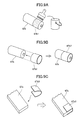
- FIGs. 8A through 9D show the cleaning roller 67a, secondary roller 67b, and cleaning blade 67c according to modifications when viewed from diagonally above the construction (from a point above and to the left in Figs. 2A and 2B).
- the two-dot chain lines indicate boundaries of the region corresponding to the "effective width.”
- the peripheral surface of the secondary roller 67b at the both ends thereof is coated with coating 67b1 formed of a coating material having a low coefficient of friction, such as a fluorocarbon resin.
- the coating material is applied to the both ends of the secondary roller 67b.
- the coating 67b 1 may be formed over the entire secondary roller 67b in the paper width direction (left-to-right direction in Fig. 8A).
- the peripheral surface of the secondary roller 67b at the both ends thereof is covered with sleeves 67b2 configured of a sheet material having a low coefficient of friction.
- the sleeves 67b2 are substantially tube-shaped and are put over the ends of the secondary roller 67b.
- the sleeves 67b2 may also be formed over the entire secondary roller 67b in the paper width direction. Note that, in Fig. 9B, thickness of the sleeves 67b2 is shown to be larger than its actual thickness for explanation purposes.
- sheets 67b3 may be inserted between the secondary roller 67b and cleaning blade 67c at the both ends of the secondary roller 67b with respect to the paper width direction. More specifically, as shown in Fig. 9C, the sheets 67b3 formed of films are put on the both ends of the cleaning blade 67c.
- the sheets (films) 67b3 are formed of a material having a low coefficient of friction. Note that, in Figs. 9C and 9D, thickness of the sheet 67b3 is shown to be larger than its actual thickness for explanation purposes.
- the cleaning blade 67c has both ends 67c3 with respect to the paper width direction having a dimension (the dimension orthogonal both to the paper width direction and to the thickness direction of the cleaning blade 67c; the vertical dimension in Fig. 8D) that is shorter than the same dimension in the inner region in the paper width direction.
- the coatings 67b1, sleeves 67b2, sheets 67b3, and ends 67c3 of the cleaning blade 67c are all formed outside the region corresponding to the "effective width" (the region inside the two-dot chain lines in Figs. 8A through 8D).
- each of these components may be formed such that the inside border of the component in the paper width direction is aligned with the border of the "effective width.”
- both ends of the secondary roller 67b in the paper width direction may be formed with a smaller diameter than that in the internal region in the paper width direction.
- the parts of the secondary roller 67b having the smaller diameter may be formed in the same regions as the coating 67b1 and the like in Figs. 8A through 8D.
Landscapes
- Physics & Mathematics (AREA)
- General Physics & Mathematics (AREA)
- Electrostatic Charge, Transfer And Separation In Electrography (AREA)
- Paper Feeding For Electrophotography (AREA)
- Feeding Of Articles By Means Other Than Belts Or Rollers (AREA)
- Cleaning In Electrography (AREA)
Abstract
Description
- This application claims priority from
Japanese Patent Application No. 2005- 181071 filed June 21, 2005 - The disclosure relates to a belt cleaning device for cleaning a surface of a belt on which a conveying object is supported and conveyed. The disclosure also relates to an image forming apparatus for forming images with a developing agent such as toner.
- Image forming apparatuses employing a conveying belt that supports and conveys sheets of paper for image formation are well known in the art. One such image forming apparatus disclosed in
U.S. Patent Application Publication No. 2004/253013 (corresponding toJapanese Patent Application Publication No. 2004-294471 - In the image forming apparatus described in
U.S. Patent Application Publication No. 2004/253013 , the conveying belt is a seamless, endless belt. A plurality of the process units is arranged along the conveying direction of the belt with each process unit disposed in confrontation with the surface of the conveying belt. The process units accommodate toner in one of the colors cyan, magenta, yellow, and black to support multicolor image formation. - The image forming apparatus disclosed in
U.S. Patent Application Publication No. 2004/253013 performs a calibration process to correct problems in color registration. In this calibration process, the image forming apparatus forms a toner pattern on the surface of the conveying belt and detects the density of the pattern using a sensor disposed in confrontation with the surface of the conveying belt. The image forming apparatus also has a cleaning unit disposed near the sensor and confronting the surface of the conveying belt for removing the toner pattern after calibration. The cleaning unit includes an electrostatic brush disposed in confrontation with the surface of the conveying belt and capable of applying a predetermined bias voltage, a secondary roller using electrostatic attraction to remove toner deposited on the electrostatic brush, and a waste toner box encompassing the electrostatic brush and secondary roller for collecting waste toner. - In view of the foregoing, it is an object of one aspect of the invention to provide a belt cleaning device employed in an image forming apparatus, in order to enhance durability of a belt and the belt cleaning device and to improve cleaning effectiveness of the belt.
In order to attain the above and other objects, the invention may provide a belt cleaning device for cleaning a surface of a belt that conveys a conveying object. The belt cleaning device includes a cleaning roller, a backup roller, and a roller-pressing-state setting mechanism. The cleaning roller is disposed in confrontation with the surface of the belt. The backup roller is disposed in confrontation with the cleaning roller with the belt interposed between the cleaning roller and the backup roller. The roller-pressing-state setting mechanism selectively sets a state of the backup roller to a first state in which the backup roller is pressed against the cleaning roller via the belt, allowing a first pressure to be applied between the cleaning roller and the surface of the belt, and a second state in which a second pressure is applied between the cleaning roller and the surface of the belt. The second pressure is less than the first pressure.
According to another aspect, the invention may also provide an image forming apparatus. The image forming apparatus includes an endless belt, a cleaning roller, a backup roller, and a roller-pressing-state setting mechanism. The endless belt has an outer surface. The endless belt conveys a conveying object on the outer surface. The cleaning roller is disposed in confrontation with the outer surface of the endless belt. The backup roller is disposed in confrontation with the cleaning roller with the endless belt interposed between the cleaning roller and the backup roller. The roller-pressing-state setting mechanism selectively sets a state of the backup roller to a first state in which the backup roller is pressed against the cleaning roller via the endless belt, allowing a first pressure to be applied between the cleaning roller and the outer surface of the endless belt, and a second state in which a second pressure is applied between the cleaning roller and the outer surface of the endless belt. The second pressure is less than the first pressure. - Illustrative aspects in accordance with the invention will be described in detail with reference to the following figures wherein:
- Fig. 1 is a vertical cross-sectional view of a laser printer according to illustrative aspects of the invention;
- Fig. 2A is an enlarged cross-sectional view of the laser printer in Fig. 1 around a belt cleaner region in a pressing release state;
- Fig. 2B is an enlarged cross-sectional view of the laser printer in Fig. 1 around the belt cleaner region in a pressing state;
- Fig. 2C is a perspective view schematically showing a roller shaft holder and a roller case of the belt cleaner;
- Fig. 3A is an enlarged cross-sectional view of a belt cleaner in a pressing release state according to a first modification of a backup unit;
- Fig. 3B is an enlarged cross-sectional view of the belt cleaner in a pressing state according to the first modification of the backup unit;
- Fig. 4A is an enlarged cross-sectional view of a belt cleaner in a pressing release state according to a second modification of a backup unit;
- Fig. 4B is an enlarged cross-sectional view of the belt cleaner in a pressing state according to the second modification of the backup unit;
- Fig. 5A is an enlarged cross-sectional view of a belt cleaner in a pressing release state according to a third modification of a backup unit;
- Fig. 5B is an enlarged cross-sectional view of the belt cleaner in a pressing state according to the third modification of the backup unit;
- Fig. 6A is an enlarged cross-sectional view of a belt cleaner according to a modification of a cleaning unit;
- Fig. 6B is an enlarged cross-sectional view of the belt cleaner shown in Fig. 6A, in which a cleaning roller rotates in an opposite direction;
- Fig. 6C is an enlarged cross-sectional view of a belt cleaner according to another modification of a cleaning unit;
- Fig. 6D is an enlarged cross-sectional view of the belt cleaner shown in Fig. 6C, in which a cleaning roller rotates in an opposite direction;
- Fig. 7 is an enlarged cross-sectional view showing a peripheral edge of a cleaning roller according to a modification;
- Fig. 8A is an explanatory diagram showing a secondary roller and a cleaning blade according to a modification, in which both ends of the secondary roller is coated with coating;
- Fig. 8B is an explanatory diagram showing a secondary roller and a cleaning blade according to another modification, in which both ends of the secondary roller is covered with sleeves;
- Fig. 8C is an explanatory diagram showing a secondary roller and a cleaning blade according to another modification, in which sheets are put on both ends of the cleaning blade;
- Fig. 8D is an explanatory diagram showing a secondary roller and a cleaning blade according to another modification, in which the cleaning blade has both ends having a shorter dimension;
- Fig. 9A is an explanatory diagram showing that coating material is applied to the end of the secondary roller shown in Fig. 8A;
- Fig. 9B is an explanatory diagram showing that the sleeves are put over the end of the secondary roller shown in Fig. 8B;
- Fig. 9C is an explanatory diagram showing that the sheets are put on the both ends of the cleaning blade shown in Fig. 8C; and
- Fig. 9D is a side view showing the secondary roller, cleaning blade, and sheets according to the modification of Fig. 8C.
- A belt cleaning device and an image forming apparatus according to illustrative aspects of the invention will be described while referring to Figs. 1 through 2C.
- Fig. 1 is a side cross-sectional view of a laser printer 1 according to illustrative aspects of the invention. In the following description, the right side of the laser printer 1 in Fig. 1 will be referred to as the "front side," while the left side will be referred to as the "rear side." The expressions "front", "rear", "upper", and "lower" are used to define the various parts when the laser printer 1 is disposed in an orientation in which it is intended to be used.
- The laser printer 1 includes a
paper cassette 20,process cartridges 30,scanning units 40, apaper conveying unit 50, atransfer unit 60, a fixingunit 70, adischarge unit 80, and acontrol unit 90. - The laser printer 1 also includes a
main casing 12 that is shaped to cover a main frame (not shown). The main frame functions to support a driving force transmitting mechanism configured of motors and gears. Atop cover 14 is mounted on the top of themain casing 12. Thetop cover 14 hasribs 14a extending downward from lower edges of thetop cover 14 on the rear side thereof and having through-holes formed near the bottom ends thereof. Support shafts protruding from themain casing 12 at positions corresponding to theribs 14a are inserted through the through-holes formed in theribs 14a for pivotally supporting thetop cover 14. Hence, thetop cover 14 can pivotally move open and closed over themain casing 12 about the support shafts. Adischarge opening 12a is formed in the upper rear section of themain casing 12 above the rear side of thetop cover 14. Adischarge tray 14b is also formed on the top surface of thetop cover 14 for supporting sheet-like paper P discharged through thedischarge opening 12a. - The
paper cassette 20 is detachably mounted in a lower section of themain casing 12. Thepaper cassette 20 is capable of accommodating a sheet-like paper P in a stacked state. - The
paper cassette 20 includes acassette case 21 forming the outer casing thereof, and a paper-pressingplate 23 and aseparating pad 25 disposed within thecassette case 21. The paper-pressingplate 23 is a plate-shaped member that functions to support a stack of paper. The paper-pressingplate 23 is pivotally supported about an end on the rear side (the end farthest from theseparating pad 25 in Fig. 1). A spring (not shown) is disposed beneath the front end of the paper-pressing plate 23 (the end nearest theseparating pad 25 in Fig. 1) for urging the front end upward. Theseparating pad 25 is disposed near the front end of thecassette case 21 and downstream of the paper-pressingplate 23 in a paper-conveying direction. Acompression spring 27 is disposed beneath theseparating pad 25 for urging theseparating pad 25 upward. The top surface of the separating pad 25 (the surface over which the paper P is conveyed) is a separating surface configured of a material having a higher coefficient of friction with the paper P than the coefficient of friction between two sheets of paper P (such as felt or rubber). Theseparating pad 25 functions to separate the sheets of paper P so that the paper P is conveyed toward an image forming unit (process cartridges 30 and the like) in themain casing 12 for image formation one sheet at a time. - A
follow roller 29 is disposed in an upper end of thecassette case 21 on the front side thereof and at a position downstream of theseparating pad 25 in the paper-conveying direction. Thefollow roller 29 rotates freely in thecassette case 21 and functions to guide sheets of the paper P separated by theseparating pad 25 and conveyed one sheet at a time toward the image forming unit. - A plurality of the process cartridges 30 (30Y, 30M, 30C, and 30K) constituting the image forming unit are detachably mounted in the
main casing 12 above thepaper cassette 20. Theprocess cartridges - Each
process cartridge 30 includes acartridge case 31; and aphotosensitive drum 32 on which latent images are formed, a developingroller 33 for bearing toner on the peripheral surface thereof to develop the latent images formed on thephotosensitive drum 32, and asupply roller 34 for supplying toner to the peripheral surface of the developingroller 33, all of which are rotatably supported in thecartridge case 31. - In a side view, the
photosensitive drum 32 is disposed in a longitudinal end of the cartridge case 31 (the bottom end in Fig. 1) so that a portion of the peripheral surface of thephotosensitive drum 32 is exposed outside of thecartridge case 31 through an opening formed in the end of thecartridge case 31. The developingroller 33 is formed of a synthetic rubber material and is positioned so that the peripheral surface of the developingroller 33 contacts thephotosensitive drum 32. Thesupply roller 34 is formed of a foam sponge material and contacts the developingroller 33 with pressure. Thephotosensitive drum 32, developingroller 33, andsupply roller 34 are driven to rotate via the driving force transmitting mechanism provided in the main frame. Further, a predetermined developing bias voltage can be applied between thephotosensitive drum 32 and developingroller 33. Acharger 35 is disposed in confrontation with the peripheral surface of eachphotosensitive drum 32 at a position upstream of the area of contact between thephotosensitive drum 32 and developingroller 33 with respect to the rotational direction of the photosensitive drum 32 (indicated by an arrow in Fig. 1). Thecharger 35 charges the peripheral surface of thephotosensitive drum 32 with a uniform charge. - The
scanning units 40 are provided inside themain casing 12 for each of theprocess cartridges 30 for irradiating a laser beam on the respective photosensitive drums 32 (indicated by a single-dot chain line in Fig. 1). Eachscanning unit 40 includes ascanner case 41, apolygon mirror 42a, apolygon motor 42b, alens 43, and a reflectingmirror 44. Thepolygon motor 42b is fixed to thescanner case 41 and has a drive shaft for supporting thepolygon mirror 42a. Thepolygon motor 42b is capable of driving thepolygon mirror 42a to rotate at a predetermined rotational speed. While thepolygon motor 42b drives thepolygon mirror 42a to rotate in this way, a laser light emitting unit (not shown) generates a laser beam based on image data. The laser beam is deflected by therotating polygon mirror 42a and scanned along a width direction of the paper. Thelens 43 and reflectingmirror 44 are supported within thescanner case 41 and are aligned so that the laser beam deflected by thepolygon mirror 42a is irradiated onto the peripheral surface of thephotosensitive drum 32. - The
paper conveying unit 50 is disposed inside themain casing 12 for conveying the paper P toward theprocess cartridges 30. Thepaper conveying unit 50 includes apickup roller 51, a feedingroller 52, a conveying roller 53,registration rollers 54, and apaper guide 55. - The
pickup roller 51 is rotatably supported on the main frame (not shown). Thepickup roller 51 is driven to rotate via the driving force transmitting mechanism provided on the main frame. During an image forming operation, thepickup roller 51 contacts with a predetermined pressure the stack of paper P urged upward by the paper-pressingplate 23. The feedingroller 52 is also rotatably supported in the main frame and is configured to rotate via the driving force transmitting mechanism. The feedingroller 52 is disposed in confrontation with theseparating pad 25 so that the peripheral surface of the feedingroller 52 contacts theseparating pad 25 with a predetermined force. The conveying roller 53 is rotatably supported in the main frame and a position opposing thefollow roller 29 and farther frontward than the separating pad 25 (downstream of theseparating pad 25 in the rotational direction of the feeding roller 52). The conveying roller 53 is driven to rotate via the driving force transmitting mechanism. Theregistration rollers 54 are also rotated via the driving force transmitting mechanism and function to adjust the direction and conveying timing of the paper P. Thepaper guide 55 functions to receive the paper P conveyed by theregistration rollers 54 and to guide the paper P toward theprocess cartridges 30. - The
transfer unit 60 is disposed inside themain casing 12 between thepaper cassette 20 and theprocess cartridges 30. Thetransfer unit 60 includes abelt 61,transfer rollers 62, adrive roller 63, asupport roller 64, a density-detectingunit 65, and abelt cleaner 66 serving as a belt cleaning device. - The
belt 61 is formed of a synthetic resin, such as polycarbonate or polyimide, or an elastomer such as synthetic rubber. Thebelt 61 is formed without seams and has a longitudinal direction along the paper-conveying direction. Thebelt 61 is formed slightly wider than the width of a maximum sized sheet of paper P that can be used in the laser printer 1. Hence, when a sheet of maximum size is supported on the surface of thebelt 61, the surface of thebelt 61 is exposed on the widthwise sides of the paper P. In this description, the width of thebelt 61 corresponding to the width of a maximum sized sheet of paper P will be referred to as the "effective width." As shown in Fig. 1, thebelt 61 is looped around thetransfer rollers 62,drive roller 63, andsupport roller 64 when viewed from the side. - The
transfer rollers 62 are rotatably supported at positions confronting each of thephotosensitive drums 32 provided in theprocess cartridges belt 61 interposed between thetransfer rollers 62 and the photosensitive drums 32. Together with theprocess cartridges 30, thetransfer rollers 62 constitute the image forming unit. A transfer bias voltage can be applied between thetransfer rollers 62 andphotosensitive drums 32 for transferring toner from the peripheral surface of thephotosensitive drums 32 onto the surface of a sheet of paper P supported on thebelt 61. - The
drive roller 63 andsupport roller 64 are rotatably supported on a transfer unit frame (not shown) at positions that stretch thebelt 61 taut in the paper-conveying direction. Thedrive roller 63 is driven to rotate in a direction indicated by the arrow in Fig. 1 via the driving force transmitting mechanism in order to move thebelt 61 circularly in the direction indicated by arrows in Fig. 1. More specifically, thedrive roller 63 is disposed near theblack process cartridge 30K, positioned farthest rearward of theprocess cartridges 30, while thesupport roller 64 is disposed near theyellow process cartridge 30Y, positioned farthest frontward of theprocess cartridges 30. Hence, thebelt 61 is supported on thedrive roller 63 andsupport roller 64 below theprocess cartridges 30 and can support a sheet of paper P on a top surface (anouter surface 61a shown in Figs. 2A and 2B) while moving along the array ofphotosensitive drums 32 provided in theprocess cartridges 30. - The density-detecting
unit 65 is disposed below thedrive roller 63 and has areflective density sensor 65a. Thereflective density sensor 65a generates signals corresponding to the density of toner on the surface of thebelt 61 based on the intensity of light emitted from a light-emitting unit and the intensity of light reflected off the surface of thebelt 61 and detected by a light-receiving unit. Hence, thereflective density sensor 65a can generate a signal indicating the toner density of marks formed on thebelt 61, such as a toner pattern formed for calibrating density or for adjusting color registration in the paper-conveying direction (hereinafter, both will be referred to as "image calibration"). - The
belt cleaner 66 is disposed below thebelt 61 and downstream of the density-detectingunit 65 with respect to the direction in which the belt moves on the lower side. Thebelt cleaner 66 is also positioned to confront the surface of thebelt 61 in order to remove foreign matter that has deposited on the surface of thebelt 61. A more detailed description of thebelt cleaner 66 will be given later. - The fixing
unit 70 is disposed inside themain casing 12 and downstream of thetransfer unit 60 in the paper-conveying direction. The fixingunit 70 functions to fix a toner image formed on the surface of the paper P to the paper P. The fixingunit 70 includes aheating roller 71 and apressure roller 72. Theheating roller 71 is configured of a metal cylinder whose surface has been treated by a release agent, and a halogen lamp accommodated inside the cylinder. Theheating roller 71 is driven to rotate by the driving force transmitting mechanism. Thepressure roller 72 is a roller formed of silicon rubber that is rotatably supported in confrontation with theheating roller 71. Thepressure roller 72 presses against theheating roller 71 with a predetermined pressure and follows the rotation of theheating roller 71. - The
discharge unit 80 is disposed inside themain casing 12 in a rearmost section thereof for discharging the paper P out of the laser printer 1 after the paper P has passed through the fixingunit 70. Thedischarge unit 80 includes apaper guide 81, and a pair ofdischarge rollers 83. Thedischarge rollers 83 are disposed near thedischarge opening 12a and are driven to rotate by the driving force transmitting mechanism. Thepaper guide 81 functions to guide the paper P having passed through the fixingunit 70 to thedischarge rollers 83. - The
control unit 90 is accommodated in a lower section of themain casing 12. Thecontrol unit 90 is electrically connected to various motors provided on the main frame for driving various movable parts provided in theprocess cartridge 30 andpaper conveying unit 50; actuators; sensors; the laser light emitting units andpolygon motors 42b provided in thescanning units 40; and the like. Hence, thecontrol unit 90 is capable of controlling the operations and timing of theprocess cartridge 30, scanningunit 40,paper conveying unit 50,transfer unit 60, fixingunit 70, anddischarge unit 80. - Figs. 2A and 2B are enlarged views of a region inside the laser printer 1 around the
belt cleaner 66. Fig. 2C is a perspective view schematically showing aroller shaft holder 68b and aroller case 68c (described later) in thebelt cleaner 66. Thebelt cleaner 66 is configured of acleaning unit 67, and abackup unit 68 disposed so as to confront thecleaning unit 67 on the opposite side of thebelt 61. - In the illustrative aspects, the
cleaning unit 67 is disposed on the underside of the outer surface 6 1 a of thebelt 61 that supports the paper. Further, like thetransfer rollers 62 shown in Fig. 1, thebackup unit 68 in the illustrative aspects is also disposed in the space encompassed by thebelt 61. - The
cleaning unit 67 is configured of acleaning roller 67a, asecondary roller 67b, and acleaning blade 67c. When thebackup unit 68 is in the state shown in Fig. 2A (i.e., when abackup roller 68a of thebackup unit 68 described later is separated from aninner surface 61b of the belt 61), thebelt 61 drops downward by its own weight. The cleaningroller 67a is positioned below theouter surface 61a of thebelt 61 so that theouter surface 61a of thebelt 61 is in constant contact with the cleaningroller 67a. - The cleaning
roller 67a in the illustrative aspects is configured of a main roller member formed around a metal rotational shaft. The main roller member is formed primarily of a synthetic rubber mixed with carbon black so as to have a semiconductive property (with a resistance of approximately 105 through 107 ohms). The rotational shaft of the cleaningroller 67a is connected to an output terminal of a high-voltage power supply. The power supply applies a predetermined cleaning bias voltage (such as -1.4 kV) between the cleaningroller 67a and thebackup roller 68a, which is grounded. - The
secondary roller 67b is a metal roller member disposed diagonally below the cleaningroller 67a so as to contact the same. Thesecondary roller 67b is connected to an output terminal of a high-voltage power supply. The power supply applies a predetermined secondary cleaning bias voltage between thesecondary roller 67b and thecleaning roller 67a. For example, the predetermined secondary cleaning bias voltage is - 0.8 kV so that the potential of thesecondary roller 67b with respect to ground potential is -2.2 kV. - In the illustrative aspects, the cleaning
roller 67a andsecondary roller 67b are supported on the transfer unit frame mentioned above and can be driven to rotate in the direction of the arrows shown in Figs. 2A and 2B. Hence, thebelt cleaner 66 of the illustrative aspects is configured so that the peripheral surface of the cleaningroller 67a where the cleaningroller 67a contacts theouter surface 61 a of the belt 61 (i.e., a tangent to thecleaning roller 67a at the position of contact) moves opposite (in a direction counter to) the moving direction of thebelt 61 at the position of contact, as indicated by arrows in Figs. 2A and 2B. In other words, thebelt cleaner 66 of the illustrative aspects is configured such that the cleaningroller 67a is driven to rotate in a counter direction to the moving direction of thebelt 61. - In the illustrative aspects, the
rubber cleaning blade 67c is disposed in contact with the peripheral surface of thesecondary roller 67b. Thecleaning blade 67c contacts the peripheral surface of thesecondary roller 67b in a direction counter to the rotation of thesecondary roller 67b. More specifically, thecleaning blade 67c has a base end 67c1 and a free end 67c2. The base end 67c1 of thecleaning blade 67c is supported on the transfer unit frame so that the free end 67c2 on the end opposite the base end 67c1 contacts thesecondary roller 67b. The direction that thecleaning blade 67c extends from the base end 67c1 to the free end 67c2 is opposite, or counter to, the rotational direction of thesecondary roller 67b at the point of contact with the free end 67c2. Thecleaning blade 67c is in a substantially horizontal orientation at a position lower than the rotational axis of thesecondary roller 67b so that the free end 67c2 contacts the peripheral surface of thesecondary roller 67b downstream of the lowest point of thesecondary roller 67b in the rotational direction of the same. - When the
belt 61 is being moved circularly, thebackup unit 68 can selectively set the position of thebackup roller 68a between a separated position (a pressing release state shown in Fig. 2A) in which thebackup roller 68a is separated a predetermined distance from theinner surface 61b of thebelt 61, and a pressing position (a pressing state shown in Fig. 2B) in which thebackup roller 68a presses against the cleaningroller 67a via thebelt 61. - The
backup unit 68 includes theroller shaft holders 68b. Theroller shaft holders 68b are provided on each end of thebackup roller 68a. As shown in Figs. 2A through 2C, theroller shaft holders 68b are shaped substantially like rectangular parallelepipeds and have a through-hole formed substantially in the center when viewed from the side. A rotational shaft 68a1 is provided in the center of thebackup roller 68a and protrudes from both ends thereof. The both ends of the rotational shaft 68a1 are rotatably inserted into the through-holes formed in theroller shaft holders 68b. As shown in Fig. 2C, thebackup unit 68 also includes theroller case 68c that houses thebackup roller 68a. Theroller case 68c is substantially box-shaped and open on the bottom. A lower portion of thebackup roller 68a is exposed at the bottom opening of theroller case 68c. Grooves 68c1 are formed in each side wall of theroller case 68c (walls on both ends of theroller case 68c with respect to the paper width direction). Each groove 68c1 extends substantially in a vertical direction. Each groove 68c1 accommodates theroller shaft holder 68b and is capable of guiding theroller shaft holder 68b in a substantially vertical direction. Compression springs 68d are configured of coil springs. Eachcompression spring 68d has a bottom end fixed to the top end of one of theroller shaft holders 68b and a top end fixed to an upper portion of theroller case 68c. - As shown in Fig. 2B, the compression springs 68d function to press the
backup roller 68a toward thebelt 61 and cleaningroller 67a by urging thebackup roller 68a downward via theroller shaft holders 68b such that thebackup roller 68a is in contact with theinner surface 61 b of thebelt 61. - The top end of the
roller case 68c is fixed to a bottom surface of aroller case holder 68e. Theroller case holder 68e is a plate-shaped member having a pivot shaft 68e1 provided on one end thereof. Theroller case holder 68e also has a free end 68e2 opposite the pivot shaft 68e1. Theroller case holder 68e is supported on the transfer unit frame via the pivot shaft 68e1 so as to be capable of pivoting about the pivot shaft 68e1 for raising and lowering the free end 68e2 in a substantially vertical direction. Aspring holder 68g formed of a plate-shaped member is supported on the transfer unit frame above the free end 68e2. A raisingspring 68h configured of a coil spring (tension spring) is connected between thespring holder 68g and the free end 68e2 of theroller case holder 68e for urging the free end 68e2 upward. - A
cam 68k is disposed at a substantially central position between the pivot shaft 68e1 and free end 68e2 of theroller case holder 68e so as to contact the top surface of theroller case holder 68e. Thecam 68k is fixed to a rotational shaft 68m1 of amotor 68m. The rotational shaft 68m1 of themotor 68m extends parallel to the pivot shaft 68e1. Themotor 68m is a stepping motor connected to thecontrol unit 90 described above (see Fig. 1). Thecontrol unit 90 controls the driving state of themotor 68m based on a rotational phase of the rotational shaft 68ml indicated by an encoder or the like (not shown). - Specifically, the
backup unit 68 is configured to place thebackup roller 68a in a "separated position" separated from theinner surface 61b of thebelt 61, as shown in Fig. 2A, when conveying thebelt 61 for performing a normal image forming operation on paper. Thebackup unit 68 is also configured to place thebackup roller 68a in a "pressing position" in which thebackup roller 68a elastically presses against thebelt 61 and cleaningroller 67a, as shown in Fig. 2B, when marks for image calibration are detected by the density-detectingunit 65. - Next, the operations and effects of the illustrative aspects described above will be described while referring to the accompanying drawings. During image calibration with the laser printer 1 of the illustrative aspects shown in Figs. 1 through 2C, the
process cartridge 30, scanningunit 40, andtransfer unit 60 are driven as follows under the control of thecontrol unit 90. - At the beginning of an image calibration operation, the
control unit 90 first begins driving thedrive roller 63 in thetransfer unit 60 and thephotosensitive drum 32, developingroller 33, andsupply roller 34 in theprocess cartridges 30. Thecontrol unit 90 begins supplying a voltage to thecleaning roller 67a andsecondary roller 67b for generating a cleaning bias voltage and a secondary cleaning bias voltage. - At this time, as shown in Fig. 2A, the
control unit 90 sets the rotational phase of themotor 68m so that the small diameter portion of thecam 68k confronts theroller case holder 68e. Consequently, theroller case holder 68e is pulled upward by the restoring force of the raisingspring 68h so that thebackup roller 68a separates from thebelt 61. Thebelt 61 is conveyed in the direction indicated by the arrow in Fig. 2A, while theouter surface 61a lightly contacts thecleaning roller 67a owing to the weight of thebelt 61. - Accordingly, the stress state of the belt 61 (the tension in the
belt 61 and the state of contact and friction with the rollers) is set to the minimum degree required for ensuring that thebelt 61 is conveyed with stability and without slipping over thedrive roller 63 andsupport roller 64 shown in Fig. 1. While the stress on thebelt 61 is greatly reduced in this way, the cleaningroller 67a removes easy-to-remove foreign matter such as paper dust, that is deposited on theouter surface 61a of thebelt 61. - Next, the
control unit 90 activates thescanning unit 40 at an appropriate timing for forming an electrostatic latent image on thephotosensitive drum 32 corresponding to calibration marks. The latent image is developed with toner borne on the surface of the developingroller 33 and the developed image is transferred onto thebelt 61 by the transfer bias. As a result, thebelt 61 bears calibration marks formed in toner on the surface thereof. The calibration marks move along with the surface of thebelt 61 as thebelt 61 moves circularly by the rotation of thedrive roller 63. As the calibration marks pass a detection position at a position opposite thereflective density sensor 65a shown in Fig. 1, the density-detectingunit 65 generates a signal corresponding to the density of toner in the calibration marks. Thecontrol unit 90 then adjusts the image based on this signal. For example, thecontrol unit 90 may adjust the developing bias or transfer bias based on the toner density. - Immediately after the density-detecting
unit 65 detects the calibration marks formed on theouter surface 61a of thebelt 61, thecontrol unit 90 rotates themotor 68m until the large diameter portion of thecam 68k confronts theroller case holder 68e, as shown in Fig. 2B. Thecam 68k forces theroller case holder 68e against the upward urging force of the raisingspring 68h so that theroller case holder 68e pivots downward about the pivot shaft 68e1. While being urged downward by the compression springs 68d, thebackup roller 68a is pressed against thebelt 61 and cleaningroller 67a. Hence, the cleaningroller 67a can reliably remove toner forming the calibration marks that firmly adheres to theouter surface 61a of thebelt 61 through electrostatic attraction. - Subsequently, the
control unit 90 again drives themotor 68m to return thebackup roller 68a to the separated position shown in Fig. 2A. This process is performed at a predetermined timing after thecleaning roller 67a has completely removed the calibration marks from theouter surface 61a of thebelt 61, that is, a predetermined time after the density-detectingunit 65 generates the signal corresponding to the toner density of the calibration marks. - The secondary cleaning bias voltage applied between the
secondary roller 67b and cleaningroller 67a causes the foreign matter removed by the cleaningroller 67a to transfer onto thesecondary roller 67b. Subsequently, the free end 67c2 of thecleaning blade 67c scrapes the foreign matter off thesecondary roller 67b so that the foreign matter falls diagonally downward (i.e., front-downward). - In the illustrative aspects described above, the
backup roller 68a actively presses against the cleaningroller 67a only when removing toner forming calibration marks that firmly adheres to theouter surface 61 a of thebelt 61 through electrostatic attraction. At all other times, thebackup roller 68a does not actively press against the cleaningroller 67a. This construction enables the cleaningroller 67a to clean thebelt 61 based on the condition of the foreign matter deposited on theouter surface 61a of thebelt 61, while enhancing the durability of thebelt 61, cleaningroller 67a, and the like. The construction also reduces power consumption by reducing the torque of the motor for driving the rollers to rotate. - A particular feature of the illustrative aspects is that the
backup roller 68a is separated from theinner surface 61b of thebelt 61 to disengage thebackup roller 68a from actively pressing against the cleaningroller 67a. This construction minimizes the stress applied to thebelt 61 when thebackup roller 68a is not actively applying pressure, thereby further enhancing the durability of thebelt 61. - In the illustrative aspects described above, the cleaning
roller 67a is driven to rotate in a direction counter to the moving direction of thebelt 61. In this way, a frictional force of a direction opposite the moving direction of thebelt 61 is applied to the foreign matter deposited on theouter surface 61a of thebelt 61 at the point of contact. Further, a larger surface area on the periphery of the cleaningroller 67a can contact a unit area of theouter surface 61 a of thebelt 61 in the contact position, where the unit area is a product of the conveying distance of thebelt 61 per unit time and the effective width of thebelt 61. Hence, the cleaningroller 67a can effectively remove foreign matter deposited on theouter surface 61 a of thebelt 61. - Next, modifications in the structure of the backup unit will be described, wherein like parts and components are designated with the same reference numerals to avoid duplicating description.
- Figs. 3A and 3B show a backup unit 68' according to a first modification. As in the illustrative aspects described above, the cleaning
roller 67a is positioned on the underside of theouter surface 61a of thebelt 61. Further, thebackup roller 68a is disposed above thebelt 61 and cleaningroller 67a and confronts the cleaningroller 67a with thebelt 61 interposed therebetween. - A feature of this modification is that the
backup roller 68a is pressed downward toward thebelt 61 by its own weight when the backup unit 68' is in the pressing release state shown in Fig. 3A. Accordingly, thebackup roller 68a is in constant contact with theinner surface 61b of thebelt 61. The downward force of thebackup roller 68a caused by its own weight is attenuated by the compression springs 68d, which stretch farther than their natural length when the backup unit 68' is in the pressing release state shown in Fig. 3A. - In this modification, the
roller case 68c is supported on the transfer unit frame (not shown) so as to be capable of reciprocating up and down. When the backup unit 68' is in the pressing state shown in Fig. 3B, the large diameter portion of thecam 68k presses directly downward against the top of theroller case 68c. Hence, theroller case holder 68e,spring holder 68g, and raisingspring 68h of the illustrative aspects in Figs. 2A and 2B have been eliminated from this structure. - In the first modification, the position of the
backup roller 68a changes very little between the pressing release state of Fig. 3A and the pressing state of Fig. 3B. Specifically, when setting thebackup roller 68a in the pressing state shown in Fig. 3B, thebackup roller 68a is displaced only slightly downward, owing to the elastic deformation of thebelt 61 and cleaningroller 67a caused by the increased pressure. - When the backup unit 68' is in the pressing release state shown in Fig. 3A, the
backup roller 68a is urged against thebelt 61 and cleaningroller 67a by its own weight, supported partially by the compression springs 68d. Accordingly, a weak pressure based on the weight of thebelt 61 and the attenuated weight of thebackup roller 68a is applied between theouter surface 61a of thebelt 61 and thecleaning roller 67a. Through this force, the cleaningroller 67a can more reliably remove paper dust and other easy-to-remove foreign matter deposited on theouter surface 61a of thebelt 61. However, the state of thebackup roller 68a is switched to the pressing state shown in Fig. 3B when removing toner adhered to theouter surface 61a of thebelt 61. In this way, the cleaningroller 67a can reliably remove toner forming calibration marks that firmly adheres to theouter surface 61 a of thebelt 61 through electrostatic attraction. - Figs. 4A and 4B show the backup unit 68' according to a second modification, wherein the
backup roller 68a is positioned to always bow thebelt 61 toward the cleaningroller 67a. In other words, thebackup roller 68a functions as a tension roller for applying tension to thebelt 61. This construction simplifies the structure of the device by eliminating the need for a separate tension roller. When the backup unit 68' is in the pressing release state shown in Fig. 4A, thebackup roller 68a applies the minimum pressure required for ensuring smooth conveyance of thebelt 61. Accordingly, thebackup roller 68a can constantly apply pressure without degrading the durability of thebelt 61. - In the backup unit 68' according to the second modification, the centers of the cleaning
roller 67a andbackup roller 68a are offset in the paper-conveying direction. This construction increases the area of contact between theouter surface 61a of thebelt 61 and thecleaning roller 67a, improving cleaning efficiency. In particular, a relatively large amount of surface area on theouter surface 61 a is placed in contact with the cleaningroller 67a in the pressing state shown in Fig. 4B. In this case, the cleaningroller 67a (and thebackup roller 68a) actively press against theouter surface 61a (andinner surface 61 b) of thebelt 61. Accordingly, the cleaningroller 67a can even more reliably remove toner forming calibration marks that adheres firmly to the outer surface 6 1 a through electrostatic attraction. - In a third modification shown in Figs. 5A and 5B, the cleaning
roller 67a functions as the tension roller described above instead of thebackup roller 68a in the second modification shown in Figs. 4A and 4B. In other words, thecleaning unit 67 is urged by a spring well known in the art (not shown) toward thebelt 61 to bow thebelt 61. This construction has the same operations and effects as that in the second modification described above. - As an alternative to urging the
cleaning unit 67 toward thebelt 61 with a spring, it is possible to urge thesupport roller 64 toward the belt 61 (rightward in Fig. 1, for example) with a spring well known in the art in order to apply tension to thebelt 61. In this case, thecleaning unit 67 is fixed to the belt cleaner 66 (main casing 12) so that the cleaningroller 67a bows thebelt 61. Alternatively, both thecleaning unit 67 andsupport roller 64 may be urged toward thebelt 61 with springs. - Next, modifications of the cleaning unit will be described with reference to Figs. 6A through 6D. Fig. 6A shows a cleaning unit having a similar structure to that in the illustrative aspects shown in Figs. 2A and 2B. However, while the
cleaning blade 67c is substantially horizontal in orientation in the cleaning unit of Figs. 2A and 2B, thecleaning blade 67c in this modification is oriented with the base end 67c1 positioned slightly above the free end 67c2. With this construction, foreign matter transferred onto thesecondary roller 67b falls diagonally downward (i.e., front-downward) when scraped off by the free end 67c2 of thecleaning blade 67c. - In the
cleaning unit 67 of the illustrative aspects shown in Figs. 2A and 2B, thesecondary roller 67b is configured so that its lower end protrudes farther downward than the lower end of the cleaningroller 67a. However, in the structure shown in Fig. 6A, the lower end of thesecondary roller 67b does not protrude lower than the lower edge of the cleaningroller 67a but is positioned at substantially the same height or slightly higher than the lower edge of the cleaningroller 67a. Further, thecleaning blade 67c in the structure shown in Fig. 6A does not protrude farther downward than the lower edge of thesecondary roller 67b. Hence, thecleaning unit 67 having this structure is more compact in the height dimension, making it possible to produce a more compact laser printer 1. - The
cleaning unit 67 shown in Fig. 6B has an identical structure to that in Fig. 6A, except that the cleaningroller 67a rotates in the opposite direction. This construction has the same operations and effects as those in Fig. 6A. - In the
cleaning unit 67 shown in Fig. 6C, the positions of thesecondary roller 67b andcleaning blade 67c are opposite those in Fig. 6B so that thesecondary roller 67b is downstream of the cleaningroller 67a in the conveying direction of thebelt 61. Further, the rotating direction of thesecondary roller 67b is opposite that in the structure of Fig. 6B. In this construction, thecleaning blade 67c is also slanted in the opposite direction so as to contact thesecondary roller 67b in a direction counter to the rotating direction of thesecondary roller 67b. Accordingly, the free end 67c2 of thecleaning blade 67c scrapes off foreign matter transferred onto thesecondary roller 67b in a direction diagonally upstream in the conveying direction of thebelt 61. In other words, foreign matter scraped off of thesecondary roller 67b by the free end 67c2 of thecleaning blade 67c falls diagonally downward and upstream in the conveying direction of the belt 61 (i.e., rear-downward). Accordingly, it is possible to suppress foreign matter from scattering downstream of the cleaningroller 67a in the conveying direction of the belt 61 (that is, toward the cleaning side), thereby more effectively cleaning thebelt 61. As described above, this construction can also reduce the size of thecleaning unit 67 in the height dimension. - The
cleaning unit 67 shown in Fig. 6D has an identical structure to that in Fig. 6C, except that the cleaningroller 67a rotates in the opposite direction. This construction has the same operations and effects as those in Fig. 6C. - Next, a modification of the cleaning
roller 67a, which can be applied to the illustrative aspects and the modifications described above, will be described with reference to Fig. 7. Fig. 7 is an enlarged vertical cross-sectional view showing a peripheral edge of the cleaningroller 67a according to the modification. - In this modification, the cleaning
roller 67a is formed of a foam synthetic resin such as a foam sponge, having a plurality of cells 67a1 formed therein. The outer periphery of the cleaningroller 67a is configured of a foam skin 67a2. The foam skin 67a2 has a plurality of open cells 67a3 opening outward from the cleaningroller 67a. Protrusions 67a4 are formed between adjacent open cells 67a3. - In this modification, the cleaning
roller 67a is driven to rotate in a direction indicated by an arrow R in Fig. 7 that is counter to a conveying direction F of thebelt 61. - With this construction, the protrusions 67a4 scrape off foreign matter deposited on the
outer surface 61a of thebelt 61, such as a polymerized toner T when the foam skin 67a2 is in contact with theouter surface 61a of thebelt 61, and the polymerized toner T is effectively captured in the open cells 67a3, thereby effectively cleaning theouter surface 61 a of thebelt 61. - Conventionally, polymerized toner T that becomes deposited on the
outer surface 61 a of thebelt 61 has been difficult to remove therefrom. However, this construction effectively removes the polymerized toner T from theouter surface 61a of thebelt 61. - Further, it is preferable to use the
belt 61 formed of an elastomer, since elastomer has a high mechanical durability. However, foreign matter readily adheres to theelastomer belt 61 due to the coarseness of the belt surface. This structure of the present modification can effectively remove foreign matter deposited on the surface of thebelt 61, even when thebelt 61 is formed of elastomer. - As described above, a state of the
backup roller 68a may include the position of thebackup roller 68a relative to thecleaning roller 67a, for example. In this case, the pressing state may indicate a pressing position of thebackup roller 68a in which thebackup roller 68a applies pressure to thecleaning roller 67a (or thecleaning roller 67a applies pressure to thebackup roller 68a). The pressing release state (see Fig. 2A) may indicate a separated position in which thebackup roller 68a and cleaningroller 67a (and belt 61) are separated a predetermined distance. Alternatively, the pressing release state (see Figs. 3A, 4A, and 5A) may indicate a position displaced from the pressing position in a direction away from the cleaningroller 67a (a very small distance sufficient to relieve the pressure and allow the elastically compressed rollers andbelt 61 to be restored to their original shapes) to achieve a state in which thebackup roller 68a is not actively pressing against the cleaningroller 67a (for example, a state in which only the weight of thebackup roller 68a is entirely or partially applied to thecleaning roller 67a). - The state of the
backup roller 68a may include a pressing state in which thebackup roller 68a presses against the cleaningroller 67a via thebelt 61 when thebackup roller 68a is in constant contact with the inside surface of thebelt 61, for example. In this case, the pressing release state (see Figs. 3A, 4A, and 5A) may include a state in which thebackup roller 68a is not actively pressing against the cleaningroller 67a (for example, a state in which only the weight of thebackup roller 68a is applied to thecleaning roller 67a). - While the invention has been described in detail with reference to specific illustrative aspects and modifications thereof, these were merely considered illustrative aspects by the inventors when applying for a patent. It would be apparent to those skilled in the art that many modifications and variations may be made therein without departing from the spirit of the invention, the scope of which is defined by the attached claims. The following are additional modifications that can be added under the first-to-file principle, but it should be apparent that the invention is not limited to these examples. A limited interpretation of the invention based on the above illustrative aspects and modifications thereof and the following appended modifications is not allowed as it would be unfairly detrimental to the profits of inventors rushing to file under the first-to-file principle, as the invention may be exploited by imitators, and runs counter to the patent law established for the protection and utilization of inventions.
- (i) The invention may be applied to other apparatuses than an image forming apparatus and to other types of image forming apparatuses other than a laser printer. Further, the invention may be applied to a monochromatic image forming apparatus that employs only one process cartridge.
- (ii) The
belt 61 in the illustrative aspects described above may be configured of a plastomer such as polycarbonate or polyimide, or an elastomer such as a synthetic resin. Thebelt 61 may also be configured of plastomer that is coated with elastomer. Thebelt 61 may also have a multilayer structure configured of a thin metal plate and a plastomer and/or elastomer. Thebelt 61 may also function as an intermediate transfer belt for receiving a toner image temporarily transferred from thephotosensitive drum 32 and subsequently transferring the toner image onto paper. - (iii) The
cleaning roller 67a may be configured to contact theouter surface 61a of thebelt 61 by moving thecleaning unit 67 upward only when thebelt 61 is moving. - (iv) The backup unit 68' shown in Figs. 3A and 3B is configured so that the
backup roller 68a contacts theinner surface 61b of thebelt 61 with a weak force in the pressing release state due to the weight of thebackup roller 68a itself. This construction could also be implemented using the pivotingroller case holder 68e shown in Figs. 2A and 2B, for example. In this case, the raisingspring 68h could be made weaker or omitted. - (v) Another possible configuration of the
belt cleaner 66 is to place thebackup roller 68a directly over the cleaningroller 67a in the pressing release state, as shown in Fig. 3A, and to offset the rotational shaft 68a1 of thebackup roller 68a from the rotational axis of the cleaningroller 67a in the pressing state with respect to the horizontal direction (paper-conveying direction), as shown in Fig. 4B. This construction increases the area of contact between the cleaningroller 67a and theouter surface 61a of thebelt 61 in the pressing state. - (vi) The
belt cleaner 66 shown in Figs. 2A and 2B is preferably configured so that the frictional force generated in the region of contact between thesecondary roller 67b andcleaning blade 67c is smaller at both ends in the paper width direction (the direction perpendicular to the surface of the drawing) than at the inner region between the ends (the region corresponding to the "effective width" of the belt 61). Hence, through an extremely simple construction, it is possible to suppress an upward warping (upward bending) of thecleaning blade 67c at the both ends in the paper width direction. - Examples of this construction will be described with reference to Figs. 8A through 9D. Figs. 8A through 8D show the cleaning
roller 67a,secondary roller 67b, andcleaning blade 67c according to modifications when viewed from diagonally above the construction (from a point above and to the left in Figs. 2A and 2B). In Figs. 8A through 8D, the two-dot chain lines indicate boundaries of the region corresponding to the "effective width." - As shown in the example of Figs. 8A and 9A, the peripheral surface of the
secondary roller 67b at the both ends thereof is coated with coating 67b1 formed of a coating material having a low coefficient of friction, such as a fluorocarbon resin. As shown in Fig. 9A, the coating material is applied to the both ends of thesecondary roller 67b. Alternatively, thecoating 67b 1 may be formed over the entiresecondary roller 67b in the paper width direction (left-to-right direction in Fig. 8A). - As shown in the example of Figs. 8B and 9B, the peripheral surface of the
secondary roller 67b at the both ends thereof is covered with sleeves 67b2 configured of a sheet material having a low coefficient of friction. As shown in Fig. 9B, the sleeves 67b2 are substantially tube-shaped and are put over the ends of thesecondary roller 67b. Alternatively, the sleeves 67b2 may also be formed over the entiresecondary roller 67b in the paper width direction. Note that, in Fig. 9B, thickness of the sleeves 67b2 is shown to be larger than its actual thickness for explanation purposes. - As shown in the example of Figs. 8C, 9C, and 9D, sheets 67b3 may be inserted between the
secondary roller 67b andcleaning blade 67c at the both ends of thesecondary roller 67b with respect to the paper width direction. More specifically, as shown in Fig. 9C, the sheets 67b3 formed of films are put on the both ends of thecleaning blade 67c. The sheets (films) 67b3 are formed of a material having a low coefficient of friction. Note that, in Figs. 9C and 9D, thickness of the sheet 67b3 is shown to be larger than its actual thickness for explanation purposes. - In the example of Fig. 8D, the
cleaning blade 67c has both ends 67c3 with respect to the paper width direction having a dimension (the dimension orthogonal both to the paper width direction and to the thickness direction of thecleaning blade 67c; the vertical dimension in Fig. 8D) that is shorter than the same dimension in the inner region in the paper width direction. - In the structures shown in Figs. 8A through 9D described above, the coatings 67b1, sleeves 67b2, sheets 67b3, and ends 67c3 of the
cleaning blade 67c are all formed outside the region corresponding to the "effective width" (the region inside the two-dot chain lines in Figs. 8A through 8D). However, each of these components may be formed such that the inside border of the component in the paper width direction is aligned with the border of the "effective width." - Alternatively, the both ends of the
secondary roller 67b in the paper width direction may be formed with a smaller diameter than that in the internal region in the paper width direction. The parts of thesecondary roller 67b having the smaller diameter may be formed in the same regions as the coating 67b1 and the like in Figs. 8A through 8D. - (vii) It is also possible to form the
cleaning roller 67a in the modification of Fig. 7 with the foam synthetic resin only on the outer periphery of the cleaningroller 67a. Further, the foam synthetic resin may have a single-cell property in which neighboring cells 67a1 are independent and are not in communication with each other, or may have a continuous-cell property in which adjacent cells 67a1 are formed in communication with each other. Also, the cleaningroller 67a in the modification of Fig. 7 may be configured to rotate in the opposite direction. - (viii) In addition to the structural examples disclosed in the above illustrative aspects and modifications, the operational and functional components constituting means for solving the problems of the invention may have any structure capable of achieving these operations and functions.
Claims (22)
- A belt cleaning device for cleaning a surface of a belt that conveys a conveying object, comprising:a cleaning roller disposed in confrontation with the surface of the belt;a backup roller disposed in confrontation with the cleaning roller with the belt interposed between the cleaning roller and the backup roller; anda roller-pressing-state setting mechanism that selectively sets a state of the backuproller to:a first state in which the backup roller is pressed against the cleaning roller via the belt, allowing a first pressure to be applied between the cleaning roller and the surface of the belt; anda second state in which a second pressure is applied between the cleaning roller and the surface of the belt, the second pressure being less than the first pressure.
- The belt cleaning device according to claim 1, wherein the cleaning roller is in constant contact with the surface of the belt at least when the belt is moving.
- The belt cleaning device according to claim 1, wherein the cleaning roller is pressed against the surface of the belt, thereby bowing the belt.
- The belt cleaning device according to claim 1, wherein the cleaning roller is disposed below the surface of the belt when the belt cleaning device is disposed in an orientation in which the belt cleaning device is intended to be used, allowing the surface of the belt to contact the cleaning roller by weight of the belt itself.
- The belt cleaning device according to claim 1, wherein the cleaning roller is disposed below the surface of the belt when the belt cleaning device is disposed in an orientation in which the belt cleaning device is intended to be used;
wherein the backup roller is disposed above the cleaning roller; and
wherein the roller-pressing-state setting mechanism is configured in such a manner that the backup roller contacts the belt by weight of the backup roller itself in the second state. - The belt cleaning device according to claim 1, wherein the roller-pressing-state setting mechanism is configured in such a manner that the backup roller is separated from the belt in the second state.
- The belt cleaning device according to claim 1, further comprising:a sensor that generates a signal in accordance with a state of the surface of the belt; anda controller that controls the roller-pressing-state setting mechanism to set the state of the backup roller based on the signal generated by the sensor.
- The belt cleaning device according to claim 1, wherein the cleaning roller has an outer periphery that contacts the surface of the belt and that is configured of a foam skin having open cells.
- The belt cleaning device according to claim 1, wherein the cleaning roller is driven to rotate in a counter direction to a conveying direction of the belt.
- The belt cleaning device according to claim 1, wherein the roller-pressing-state setting mechanism includes:a roller case;a roller-case spring having one end and another end, the one end being fixed to the roller case;a roller shaft holder that rotatably holds the backup roller, the roller shaft holder being fixed to the another end of the roller-case spring; anda cam having a large diameter portion and a small diameter portion; andwherein the large diameter portion confronts the roller case in the first state, and the small diameter portion confronts the roller case in the second state.
- The belt cleaning device according to claim 1, wherein a center of the cleaning roller and a center of the backup roller are offset in a conveying direction of the belt.
- An image forming apparatus comprising:an endless belt having an outer surface, the endless belt conveying a conveying object on the outer surface;a cleaning roller disposed in confrontation with the outer surface of the endless belt;a backup roller disposed in confrontation with the cleaning roller with the endless belt interposed between the cleaning roller and the backup roller; anda roller-pressing-state setting mechanism that selectively sets a state of the backup roller to:a first state in which the backup roller is pressed against the cleaning roller via the endless belt, allowing a first pressure to be applied between the cleaning roller and the outer surface of the endless belt; anda second state in which a second pressure is applied between the cleaning roller and the outer surface of the endless belt, the second pressure being less than the first pressure.
- The image forming apparatus according to claim 12, wherein the cleaning roller is in constant contact with the outer surface of the endless belt at least when the endless belt is moving.
- The image forming apparatus according to claim 12, wherein the conveying object is a recording medium that bears a developer image.
- The image forming apparatus according to claim 12, wherein the cleaning roller is pressed against the outer surface of the endless belt, thereby bowing the endless belt.
- The image forming apparatus according to claim 12, wherein the cleaning roller is disposed below the outer surface of the endless belt when the image forming apparatus is disposed in an orientation in which the image forming apparatus is intended to be used, allowing the outer surface of the endless belt to contact the cleaning roller by weight of the endless belt itself.
- The image forming apparatus according to claim 12, wherein the cleaning roller is disposed below the outer surface of the endless belt when the image forming apparatus is disposed in an orientation in which the image forming apparatus is intended to be used;
wherein the backup roller is disposed above the cleaning roller; and
wherein the roller-pressing-state setting mechanism is configured in such a manner that the backup roller contacts the endless belt by weight of the backup roller itself in the second state. - The image forming apparatus according to claim 12, wherein the roller-pressing-state setting mechanism is configured in such a manner that the backup roller is separated from the endless belt in the second state.
- The image forming apparatus according to claim 12, further comprising a controller that controls the roller-pressing-state setting mechanism to set the state of the backup roller to the first state when a pattern for image calibration is formed on the outer surface of the endless belt with a developing agent.
- The image forming apparatus according to claim 19, further comprising a sensor that generates a signal based on density of the developing agent on the outer surface of the endless belt,
wherein the controller controls the roller-pressing-state setting mechanism to set the state of the backup roller based on the signal generated by the sensor. - The image forming apparatus according to claim 12, wherein the endless belt is formed of elastomer; and
wherein the cleaning roller has an outer periphery that is configured of a foam skin having open cells. - The image forming apparatus according to claim 12, wherein the cleaning roller is driven to rotate in a counter direction to a conveying direction of the endless belt.
Applications Claiming Priority (1)
| Application Number | Priority Date | Filing Date | Title |
|---|---|---|---|
| JP2005181071A JP4475179B2 (en) | 2005-06-21 | 2005-06-21 | Belt cleaning device and image forming apparatus |
Publications (2)
| Publication Number | Publication Date |
|---|---|
| EP1736836A1 true EP1736836A1 (en) | 2006-12-27 |
| EP1736836B1 EP1736836B1 (en) | 2008-08-06 |
Family
ID=36723064
Family Applications (1)
| Application Number | Title | Priority Date | Filing Date |
|---|---|---|---|
| EP06012553A Ceased EP1736836B1 (en) | 2005-06-21 | 2006-06-19 | Belt cleaning device with means for changing the pressure between a cleaning roller and the belt |
Country Status (5)
| Country | Link |
|---|---|
| US (1) | US7778566B2 (en) |
| EP (1) | EP1736836B1 (en) |
| JP (1) | JP4475179B2 (en) |
| AT (1) | ATE403892T1 (en) |
| DE (1) | DE602006002070D1 (en) |
Cited By (2)
| Publication number | Priority date | Publication date | Assignee | Title |
|---|---|---|---|---|
| CN103097268A (en) * | 2010-09-08 | 2013-05-08 | Itwcs(英国)有限公司 | Apparatus and method for making a roll of adhesive wide sheet material for contact cleaning |
| US9176456B2 (en) | 2013-08-09 | 2015-11-03 | Kyocera Document Solutions Inc. | Image forming unit and image forming apparatus comprising first process roller and second process roller |
Families Citing this family (10)
| Publication number | Priority date | Publication date | Assignee | Title |
|---|---|---|---|---|
| JP4682846B2 (en) * | 2005-12-27 | 2011-05-11 | ブラザー工業株式会社 | Image forming apparatus |
| JP2007178562A (en) * | 2005-12-27 | 2007-07-12 | Brother Ind Ltd | Belt cleaning device and image forming apparatus |
| JP4544180B2 (en) * | 2006-03-01 | 2010-09-15 | ブラザー工業株式会社 | Image forming apparatus |
| JP4807147B2 (en) | 2006-05-31 | 2011-11-02 | ブラザー工業株式会社 | Image forming apparatus |
| JP5327098B2 (en) * | 2010-02-26 | 2013-10-30 | ブラザー工業株式会社 | Image forming apparatus |
| JP5533643B2 (en) * | 2010-12-28 | 2014-06-25 | ブラザー工業株式会社 | Image forming apparatus and conveyance belt cleaning method |
| US9061514B2 (en) * | 2012-11-29 | 2015-06-23 | Xerox Corporation | Release agent applicator system with replaceable reservoir pad |
| JP6627329B2 (en) * | 2014-11-25 | 2020-01-08 | セイコーエプソン株式会社 | Recording device |
| CN112015068B (en) * | 2019-05-30 | 2022-11-11 | 京瓷办公信息系统株式会社 | Cleaning device and image forming apparatus including the same |
| CN115849113B (en) * | 2022-11-23 | 2026-03-03 | 宁德时代新能源科技股份有限公司 | Roller, spot inspection method and device, coiled material conveying method and device, equipment and medium |
Citations (5)
| Publication number | Priority date | Publication date | Assignee | Title |
|---|---|---|---|---|
| US4230406A (en) * | 1979-03-26 | 1980-10-28 | Xerox Corporation | Cleaning system for an electrostatic copier |
| US5797078A (en) * | 1993-07-09 | 1998-08-18 | Xerox Corporation | Photoreceptor comet prevention brush |
| US6049684A (en) * | 1998-02-17 | 2000-04-11 | Nec Corporation | Image formation apparatus |
| JP2001147598A (en) * | 1999-11-18 | 2001-05-29 | Fuji Xerox Co Ltd | Cleaning device / cleaning method, and image forming apparatus |
| US20050008404A1 (en) * | 2003-07-11 | 2005-01-13 | Canon Kabushiki Kaisha | Image forming apparatus |
Family Cites Families (24)
| Publication number | Priority date | Publication date | Assignee | Title |
|---|---|---|---|---|
| JPH0278970A (en) | 1988-09-14 | 1990-03-19 | Nippon Seiko Kk | Continuity testing machine for conductor patterns and probe coordinate setting method in continuity testing machine |
| JPH02106780A (en) | 1988-10-14 | 1990-04-18 | Fuji Xerox Co Ltd | Cleaning device for electrophotographic device |
| JPH03130790A (en) | 1989-10-17 | 1991-06-04 | Ricoh Co Ltd | Transfer device |
| JPH0442271A (en) | 1990-06-08 | 1992-02-12 | Hitachi Koki Co Ltd | Electrophotographic system printer |
| JPH04245283A (en) | 1991-01-31 | 1992-09-01 | Canon Inc | Image forming device |
| JPH04301869A (en) | 1991-03-29 | 1992-10-26 | Canon Inc | Image forming device |
| JPH05193772A (en) | 1992-01-17 | 1993-08-03 | Tokyo Electric Co Ltd | Image forming device |
| JPH05303290A (en) | 1992-04-24 | 1993-11-16 | Ricoh Co Ltd | Cleaning device for image forming device |
| JP3083907B2 (en) * | 1992-05-13 | 2000-09-04 | 沖電気工業株式会社 | Image forming device |
| JP3130790B2 (en) | 1996-03-27 | 2001-01-31 | 名古屋製酪株式会社 | Degassing package |
| JPH1195503A (en) | 1997-09-18 | 1999-04-09 | Minolta Co Ltd | Image forming apparatus and refresh method thereof |
| JPH11192768A (en) | 1997-12-29 | 1999-07-21 | Canon Inc | Image forming apparatus and method |
| US6477344B1 (en) * | 1999-05-28 | 2002-11-05 | Matsushita Electric Industrial Co., Ltd. | Image forming apparatus, transfer belt unit, cleaning device and cleaner unit used for image forming apparatus |
| JP2002031996A (en) | 2000-05-10 | 2002-01-31 | Konica Corp | Cleaning device and image forming device |
| JP2002031997A (en) | 2000-05-10 | 2002-01-31 | Konica Corp | Cleaning device and image forming device |
| US6480695B2 (en) | 2000-05-10 | 2002-11-12 | Konica Corporation | Cleaning system and image forming method |
| JP3803537B2 (en) | 2000-08-11 | 2006-08-02 | 株式会社リコー | Cleaning device, belt device, and image forming apparatus |
| US6640081B2 (en) | 2000-09-13 | 2003-10-28 | Canon Kabushiki Kaisha | Image forming apparatus including elastic cleaning blade with resin film formed only at ends thereof and process cartridge including same |
| JP2002162885A (en) | 2000-09-13 | 2002-06-07 | Canon Inc | Cleaning blade, cleaning device, process cartridge, and image forming apparatus |
| JP4245283B2 (en) | 2001-05-17 | 2009-03-25 | クボタシーアイ株式会社 | Branching method and branching structure from insertion tube |
| JP4192646B2 (en) | 2003-03-25 | 2008-12-10 | ブラザー工業株式会社 | Image forming apparatus |
| JP4301869B2 (en) | 2003-06-06 | 2009-07-22 | ヤマハ発動機株式会社 | Small planing boat |
| JP2005292416A (en) * | 2004-03-31 | 2005-10-20 | Canon Inc | Image forming apparatus |
| JP4807147B2 (en) * | 2006-05-31 | 2011-11-02 | ブラザー工業株式会社 | Image forming apparatus |
-
2005
- 2005-06-21 JP JP2005181071A patent/JP4475179B2/en not_active Expired - Fee Related
-
2006
- 2006-06-19 EP EP06012553A patent/EP1736836B1/en not_active Ceased
- 2006-06-19 DE DE602006002070T patent/DE602006002070D1/en not_active Expired - Lifetime
- 2006-06-19 AT AT06012553T patent/ATE403892T1/en not_active IP Right Cessation
- 2006-06-21 US US11/471,544 patent/US7778566B2/en active Active
Patent Citations (5)
| Publication number | Priority date | Publication date | Assignee | Title |
|---|---|---|---|---|
| US4230406A (en) * | 1979-03-26 | 1980-10-28 | Xerox Corporation | Cleaning system for an electrostatic copier |
| US5797078A (en) * | 1993-07-09 | 1998-08-18 | Xerox Corporation | Photoreceptor comet prevention brush |
| US6049684A (en) * | 1998-02-17 | 2000-04-11 | Nec Corporation | Image formation apparatus |
| JP2001147598A (en) * | 1999-11-18 | 2001-05-29 | Fuji Xerox Co Ltd | Cleaning device / cleaning method, and image forming apparatus |
| US20050008404A1 (en) * | 2003-07-11 | 2005-01-13 | Canon Kabushiki Kaisha | Image forming apparatus |
Non-Patent Citations (1)
| Title |
|---|
| PATENT ABSTRACTS OF JAPAN vol. 2000, no. 22 9 March 2001 (2001-03-09) * |
Cited By (3)
| Publication number | Priority date | Publication date | Assignee | Title |
|---|---|---|---|---|
| CN103097268A (en) * | 2010-09-08 | 2013-05-08 | Itwcs(英国)有限公司 | Apparatus and method for making a roll of adhesive wide sheet material for contact cleaning |
| CN103097268B (en) * | 2010-09-08 | 2016-08-03 | Itw有限公司 | Apparatus and method for manufacturing wide rolls of adhesive sheet material for contact cleaning |
| US9176456B2 (en) | 2013-08-09 | 2015-11-03 | Kyocera Document Solutions Inc. | Image forming unit and image forming apparatus comprising first process roller and second process roller |
Also Published As
| Publication number | Publication date |
|---|---|
| US20060285872A1 (en) | 2006-12-21 |
| JP2007001680A (en) | 2007-01-11 |
| JP4475179B2 (en) | 2010-06-09 |
| DE602006002070D1 (en) | 2008-09-18 |
| EP1736836B1 (en) | 2008-08-06 |
| ATE403892T1 (en) | 2008-08-15 |
| US7778566B2 (en) | 2010-08-17 |
Similar Documents
| Publication | Publication Date | Title |
|---|---|---|
| JP7362029B2 (en) | Cleaning device, belt device, and image forming device | |
| US8005404B2 (en) | Developing device and image forming apparatus having the same | |
| JP3611904B2 (en) | Unit-type feed member device | |
| US8000628B2 (en) | Image forming apparatus with a cleaning device | |
| US7778566B2 (en) | Belt cleaning device and image forming apparatus | |
| JP4482296B2 (en) | Electrophotographic equipment | |
| CN2884269Y (en) | Image forming device and belt unit | |
| JP6788818B2 (en) | Sheet transfer device, image reader and image forming device | |
| US6463235B1 (en) | Light-sensitive drum mounting/demounting structure, light-sensitive unit provided with the same structure and image-forming device with the same unit | |
| JP5613612B2 (en) | Image forming apparatus | |
| US7113199B2 (en) | Tandem image forming device with reduced footprint | |
| JP4770158B2 (en) | Image forming apparatus | |
| CN100338535C (en) | Image forming apparatus | |
| US7619799B2 (en) | Light scanning device and image forming apparatus using the same | |
| US7400338B2 (en) | Image forming apparatus with temperature detection | |
| JP7415704B2 (en) | Sheet conveyance device and image forming device | |
| JP4610939B2 (en) | Image forming apparatus | |
| US7346304B2 (en) | Transfer device having guiding member that guides recording medium to transfer position | |
| JP7218526B2 (en) | image forming device | |
| JP4886343B2 (en) | Image forming apparatus | |
| JP5433530B2 (en) | Image forming apparatus and transfer surface processing method of intermediate transfer belt | |
| JP4340474B2 (en) | Transfer conveying apparatus and image forming apparatus | |
| JP2004219654A (en) | Image forming device | |
| JP2005352357A (en) | Double-sided transfer device and image forming apparatus | |
| JP2005172906A (en) | Process cartridge and electrophotographic image forming apparatus |
Legal Events
| Date | Code | Title | Description |
|---|---|---|---|
| PUAI | Public reference made under article 153(3) epc to a published international application that has entered the european phase |
Free format text: ORIGINAL CODE: 0009012 |
|
| AK | Designated contracting states |
Kind code of ref document: A1 Designated state(s): AT BE BG CH CY CZ DE DK EE ES FI FR GB GR HU IE IS IT LI LT LU LV MC NL PL PT RO SE SI SK TR |
|
| AX | Request for extension of the european patent |
Extension state: AL BA HR MK YU |
|
| 17P | Request for examination filed |
Effective date: 20070316 |
|
| AKX | Designation fees paid |
Designated state(s): AT BE BG CH CY CZ DE DK EE ES FI FR GB GR HU IE IS IT LI LT LU LV MC NL PL PT RO SE SI SK TR |
|
| GRAP | Despatch of communication of intention to grant a patent |
Free format text: ORIGINAL CODE: EPIDOSNIGR1 |
|
| GRAS | Grant fee paid |
Free format text: ORIGINAL CODE: EPIDOSNIGR3 |
|
| GRAA | (expected) grant |
Free format text: ORIGINAL CODE: 0009210 |
|
| AK | Designated contracting states |
Kind code of ref document: B1 Designated state(s): AT BE BG CH CY CZ DE DK EE ES FI FR GB GR HU IE IS IT LI LT LU LV MC NL PL PT RO SE SI SK TR |
|
| REG | Reference to a national code |
Ref country code: GB Ref legal event code: FG4D |
|
| REG | Reference to a national code |
Ref country code: CH Ref legal event code: EP |
|
| REG | Reference to a national code |
Ref country code: IE Ref legal event code: FG4D |
|
| REF | Corresponds to: |
Ref document number: 602006002070 Country of ref document: DE Date of ref document: 20080918 Kind code of ref document: P |
|
| PG25 | Lapsed in a contracting state [announced via postgrant information from national office to epo] |
Ref country code: IS Free format text: LAPSE BECAUSE OF FAILURE TO SUBMIT A TRANSLATION OF THE DESCRIPTION OR TO PAY THE FEE WITHIN THE PRESCRIBED TIME-LIMIT Effective date: 20081206 Ref country code: NL Free format text: LAPSE BECAUSE OF FAILURE TO SUBMIT A TRANSLATION OF THE DESCRIPTION OR TO PAY THE FEE WITHIN THE PRESCRIBED TIME-LIMIT Effective date: 20080806 Ref country code: LT Free format text: LAPSE BECAUSE OF FAILURE TO SUBMIT A TRANSLATION OF THE DESCRIPTION OR TO PAY THE FEE WITHIN THE PRESCRIBED TIME-LIMIT Effective date: 20080806 |
|
| PG25 | Lapsed in a contracting state [announced via postgrant information from national office to epo] |
Ref country code: ES Free format text: LAPSE BECAUSE OF FAILURE TO SUBMIT A TRANSLATION OF THE DESCRIPTION OR TO PAY THE FEE WITHIN THE PRESCRIBED TIME-LIMIT Effective date: 20081117 Ref country code: LV Free format text: LAPSE BECAUSE OF FAILURE TO SUBMIT A TRANSLATION OF THE DESCRIPTION OR TO PAY THE FEE WITHIN THE PRESCRIBED TIME-LIMIT Effective date: 20080806 Ref country code: AT Free format text: LAPSE BECAUSE OF FAILURE TO SUBMIT A TRANSLATION OF THE DESCRIPTION OR TO PAY THE FEE WITHIN THE PRESCRIBED TIME-LIMIT Effective date: 20080806 Ref country code: SI Free format text: LAPSE BECAUSE OF FAILURE TO SUBMIT A TRANSLATION OF THE DESCRIPTION OR TO PAY THE FEE WITHIN THE PRESCRIBED TIME-LIMIT Effective date: 20080806 Ref country code: FI Free format text: LAPSE BECAUSE OF FAILURE TO SUBMIT A TRANSLATION OF THE DESCRIPTION OR TO PAY THE FEE WITHIN THE PRESCRIBED TIME-LIMIT Effective date: 20080806 |
|
| PG25 | Lapsed in a contracting state [announced via postgrant information from national office to epo] |
Ref country code: BE Free format text: LAPSE BECAUSE OF FAILURE TO SUBMIT A TRANSLATION OF THE DESCRIPTION OR TO PAY THE FEE WITHIN THE PRESCRIBED TIME-LIMIT Effective date: 20080806 |
|
| PG25 | Lapsed in a contracting state [announced via postgrant information from national office to epo] |
Ref country code: DK Free format text: LAPSE BECAUSE OF FAILURE TO SUBMIT A TRANSLATION OF THE DESCRIPTION OR TO PAY THE FEE WITHIN THE PRESCRIBED TIME-LIMIT Effective date: 20080806 Ref country code: BG Free format text: LAPSE BECAUSE OF FAILURE TO SUBMIT A TRANSLATION OF THE DESCRIPTION OR TO PAY THE FEE WITHIN THE PRESCRIBED TIME-LIMIT Effective date: 20081106 |
|
| PG25 | Lapsed in a contracting state [announced via postgrant information from national office to epo] |
Ref country code: RO Free format text: LAPSE BECAUSE OF FAILURE TO SUBMIT A TRANSLATION OF THE DESCRIPTION OR TO PAY THE FEE WITHIN THE PRESCRIBED TIME-LIMIT Effective date: 20080806 Ref country code: SK Free format text: LAPSE BECAUSE OF FAILURE TO SUBMIT A TRANSLATION OF THE DESCRIPTION OR TO PAY THE FEE WITHIN THE PRESCRIBED TIME-LIMIT Effective date: 20080806 Ref country code: PT Free format text: LAPSE BECAUSE OF FAILURE TO SUBMIT A TRANSLATION OF THE DESCRIPTION OR TO PAY THE FEE WITHIN THE PRESCRIBED TIME-LIMIT Effective date: 20090106 Ref country code: CZ Free format text: LAPSE BECAUSE OF FAILURE TO SUBMIT A TRANSLATION OF THE DESCRIPTION OR TO PAY THE FEE WITHIN THE PRESCRIBED TIME-LIMIT Effective date: 20080806 |
|
| PLBE | No opposition filed within time limit |
Free format text: ORIGINAL CODE: 0009261 |
|
| STAA | Information on the status of an ep patent application or granted ep patent |
Free format text: STATUS: NO OPPOSITION FILED WITHIN TIME LIMIT |
|
| 26N | No opposition filed |
Effective date: 20090507 |
|
| PG25 | Lapsed in a contracting state [announced via postgrant information from national office to epo] |
Ref country code: EE Free format text: LAPSE BECAUSE OF FAILURE TO SUBMIT A TRANSLATION OF THE DESCRIPTION OR TO PAY THE FEE WITHIN THE PRESCRIBED TIME-LIMIT Effective date: 20080806 |
|
| PG25 | Lapsed in a contracting state [announced via postgrant information from national office to epo] |
Ref country code: IT Free format text: LAPSE BECAUSE OF FAILURE TO SUBMIT A TRANSLATION OF THE DESCRIPTION OR TO PAY THE FEE WITHIN THE PRESCRIBED TIME-LIMIT Effective date: 20080806 |
|
| PG25 | Lapsed in a contracting state [announced via postgrant information from national office to epo] |
Ref country code: SE Free format text: LAPSE BECAUSE OF FAILURE TO SUBMIT A TRANSLATION OF THE DESCRIPTION OR TO PAY THE FEE WITHIN THE PRESCRIBED TIME-LIMIT Effective date: 20081106 Ref country code: MC Free format text: LAPSE BECAUSE OF NON-PAYMENT OF DUE FEES Effective date: 20090630 |
|
| PG25 | Lapsed in a contracting state [announced via postgrant information from national office to epo] |
Ref country code: IE Free format text: LAPSE BECAUSE OF NON-PAYMENT OF DUE FEES Effective date: 20090619 |
|
| PG25 | Lapsed in a contracting state [announced via postgrant information from national office to epo] |
Ref country code: PL Free format text: LAPSE BECAUSE OF FAILURE TO SUBMIT A TRANSLATION OF THE DESCRIPTION OR TO PAY THE FEE WITHIN THE PRESCRIBED TIME-LIMIT Effective date: 20080806 |
|
| PG25 | Lapsed in a contracting state [announced via postgrant information from national office to epo] |
Ref country code: GR Free format text: LAPSE BECAUSE OF FAILURE TO SUBMIT A TRANSLATION OF THE DESCRIPTION OR TO PAY THE FEE WITHIN THE PRESCRIBED TIME-LIMIT Effective date: 20081107 |
|
| REG | Reference to a national code |
Ref country code: CH Ref legal event code: PL |
|
| PG25 | Lapsed in a contracting state [announced via postgrant information from national office to epo] |
Ref country code: CH Free format text: LAPSE BECAUSE OF NON-PAYMENT OF DUE FEES Effective date: 20090630 Ref country code: LI Free format text: LAPSE BECAUSE OF NON-PAYMENT OF DUE FEES Effective date: 20090630 |
|
| PG25 | Lapsed in a contracting state [announced via postgrant information from national office to epo] |
Ref country code: LU Free format text: LAPSE BECAUSE OF NON-PAYMENT OF DUE FEES Effective date: 20090619 Ref country code: CH Free format text: LAPSE BECAUSE OF NON-PAYMENT OF DUE FEES Effective date: 20100630 Ref country code: LI Free format text: LAPSE BECAUSE OF NON-PAYMENT OF DUE FEES Effective date: 20100630 |
|
| PG25 | Lapsed in a contracting state [announced via postgrant information from national office to epo] |
Ref country code: HU Free format text: LAPSE BECAUSE OF FAILURE TO SUBMIT A TRANSLATION OF THE DESCRIPTION OR TO PAY THE FEE WITHIN THE PRESCRIBED TIME-LIMIT Effective date: 20090207 |
|
| PG25 | Lapsed in a contracting state [announced via postgrant information from national office to epo] |
Ref country code: TR Free format text: LAPSE BECAUSE OF FAILURE TO SUBMIT A TRANSLATION OF THE DESCRIPTION OR TO PAY THE FEE WITHIN THE PRESCRIBED TIME-LIMIT Effective date: 20080806 |
|
| PG25 | Lapsed in a contracting state [announced via postgrant information from national office to epo] |
Ref country code: CY Free format text: LAPSE BECAUSE OF FAILURE TO SUBMIT A TRANSLATION OF THE DESCRIPTION OR TO PAY THE FEE WITHIN THE PRESCRIBED TIME-LIMIT Effective date: 20080806 |
|
| REG | Reference to a national code |
Ref country code: FR Ref legal event code: PLFP Year of fee payment: 11 |
|
| REG | Reference to a national code |
Ref country code: FR Ref legal event code: PLFP Year of fee payment: 12 |
|
| REG | Reference to a national code |
Ref country code: FR Ref legal event code: PLFP Year of fee payment: 13 |
|
| PGFP | Annual fee paid to national office [announced via postgrant information from national office to epo] |
Ref country code: FR Payment date: 20180516 Year of fee payment: 13 |
|
| PGFP | Annual fee paid to national office [announced via postgrant information from national office to epo] |
Ref country code: GB Payment date: 20180403 Year of fee payment: 13 |
|
| GBPC | Gb: european patent ceased through non-payment of renewal fee |
Effective date: 20190619 |
|
| PG25 | Lapsed in a contracting state [announced via postgrant information from national office to epo] |
Ref country code: GB Free format text: LAPSE BECAUSE OF NON-PAYMENT OF DUE FEES Effective date: 20190619 |
|
| PG25 | Lapsed in a contracting state [announced via postgrant information from national office to epo] |
Ref country code: FR Free format text: LAPSE BECAUSE OF NON-PAYMENT OF DUE FEES Effective date: 20190630 |
|
| PGFP | Annual fee paid to national office [announced via postgrant information from national office to epo] |
Ref country code: DE Payment date: 20220512 Year of fee payment: 17 |
|
| REG | Reference to a national code |
Ref country code: DE Ref legal event code: R119 Ref document number: 602006002070 Country of ref document: DE |
|
| PG25 | Lapsed in a contracting state [announced via postgrant information from national office to epo] |
Ref country code: DE Free format text: LAPSE BECAUSE OF NON-PAYMENT OF DUE FEES Effective date: 20240103 |