EP1736772B1 - Test device with test element storage device - Google Patents
Test device with test element storage device Download PDFInfo
- Publication number
- EP1736772B1 EP1736772B1 EP05013396.6A EP05013396A EP1736772B1 EP 1736772 B1 EP1736772 B1 EP 1736772B1 EP 05013396 A EP05013396 A EP 05013396A EP 1736772 B1 EP1736772 B1 EP 1736772B1
- Authority
- EP
- European Patent Office
- Prior art keywords
- test
- housing
- magazine
- test elements
- measurement
- Prior art date
- Legal status (The legal status is an assumption and is not a legal conclusion. Google has not performed a legal analysis and makes no representation as to the accuracy of the status listed.)
- Not-in-force
Links
Images


Classifications
-
- G—PHYSICS
- G01—MEASURING; TESTING
- G01N—INVESTIGATING OR ANALYSING MATERIALS BY DETERMINING THEIR CHEMICAL OR PHYSICAL PROPERTIES
- G01N33/00—Investigating or analysing materials by specific methods not covered by groups G01N1/00 - G01N31/00
- G01N33/48—Biological material, e.g. blood, urine; Haemocytometers
- G01N33/483—Physical analysis of biological material
- G01N33/487—Physical analysis of biological material of liquid biological material
- G01N33/4875—Details of handling test elements, e.g. dispensing or storage, not specific to a particular test method
- G01N33/48757—Test elements dispensed from a stack
-
- Y—GENERAL TAGGING OF NEW TECHNOLOGICAL DEVELOPMENTS; GENERAL TAGGING OF CROSS-SECTIONAL TECHNOLOGIES SPANNING OVER SEVERAL SECTIONS OF THE IPC; TECHNICAL SUBJECTS COVERED BY FORMER USPC CROSS-REFERENCE ART COLLECTIONS [XRACs] AND DIGESTS
- Y10—TECHNICAL SUBJECTS COVERED BY FORMER USPC
- Y10T—TECHNICAL SUBJECTS COVERED BY FORMER US CLASSIFICATION
- Y10T436/00—Chemistry: analytical and immunological testing
- Y10T436/11—Automated chemical analysis
- Y10T436/111666—Utilizing a centrifuge or compartmented rotor
-
- Y—GENERAL TAGGING OF NEW TECHNOLOGICAL DEVELOPMENTS; GENERAL TAGGING OF CROSS-SECTIONAL TECHNOLOGIES SPANNING OVER SEVERAL SECTIONS OF THE IPC; TECHNICAL SUBJECTS COVERED BY FORMER USPC CROSS-REFERENCE ART COLLECTIONS [XRACs] AND DIGESTS
- Y10—TECHNICAL SUBJECTS COVERED BY FORMER USPC
- Y10T—TECHNICAL SUBJECTS COVERED BY FORMER US CLASSIFICATION
- Y10T436/00—Chemistry: analytical and immunological testing
- Y10T436/11—Automated chemical analysis
- Y10T436/112499—Automated chemical analysis with sample on test slide
-
- Y—GENERAL TAGGING OF NEW TECHNOLOGICAL DEVELOPMENTS; GENERAL TAGGING OF CROSS-SECTIONAL TECHNOLOGIES SPANNING OVER SEVERAL SECTIONS OF THE IPC; TECHNICAL SUBJECTS COVERED BY FORMER USPC CROSS-REFERENCE ART COLLECTIONS [XRACs] AND DIGESTS
- Y10—TECHNICAL SUBJECTS COVERED BY FORMER USPC
- Y10T—TECHNICAL SUBJECTS COVERED BY FORMER US CLASSIFICATION
- Y10T436/00—Chemistry: analytical and immunological testing
- Y10T436/14—Heterocyclic carbon compound [i.e., O, S, N, Se, Te, as only ring hetero atom]
- Y10T436/142222—Hetero-O [e.g., ascorbic acid, etc.]
- Y10T436/143333—Saccharide [e.g., DNA, etc.]
- Y10T436/144444—Glucose
Definitions
- the invention relates to a test device, in particular a portable test device, for determining at least one analyte concentration in a sample by means of a test element. Furthermore, the invention relates to a test element for determining at least one analyte concentration in a sample using a test device according to the invention. Such test devices and test elements are used in particular for the measurement of blood glucose concentrations.
- the monitoring of the blood glucose concentration is an essential part of the daily routine for diabetics.
- the blood glucose concentration must be determined quickly and reliably several times a day in order to be able to take appropriate medical measures if necessary.
- In order to limit the daily routine of the diabetic no more than necessary often corresponding mobile devices are used, which should be easy to transport and handle, so that the measurement of blood glucose concentration, for example, at work or in the leisure can take place.
- EP 1 488 736 A1 describes a container with a rotatable lid for reading and handling diagnostic reagents in strip form, comprising a body portion, a lid portion, a continuous band, a reagent measuring device and a storage device.
- the lid section is on the Fixed body portion and is adapted to rotate from a closed position to an open position.
- WO 96/30752 A1 describes a device for monitoring a glucose level.
- the device has a housing and a lid.
- the lid is configured to cover or release a base of the housing.
- EP 1 507 143 A1 describes an analytical instrument package with an analytical instrument embedded between one or more seal layers.
- the analytical instrument package includes a stopper portion for holding the analytical instrument, the analytical instrument protruding from the sealing layers.
- test strips are constructed, for example, such that a predetermined amount of blood is guided via a capillary system on the test strip to an electrode system.
- a blood volume of approx. 1.5 ⁇ l, in some cases also blood quantities below 1 ⁇ l, is sufficient.
- the electrode system it may, for. B. are gold electrodes, which are provided with a coating.
- the coating usually contains various enzymes and so-called mediators and causes charge carriers (for example in the form of redox molecules) to form on the electrodes within the sample, the concentration of which depends on the blood glucose concentration.
- the concentration of these charge carriers can be determined by means of the gold electrodes and a suitable measuring system, for example by means of a current-voltage measurement, so that finally it can be calculated back to the blood glucose concentration.
- a suitable measuring system for example by means of a current-voltage measurement, so that finally it can be calculated back to the blood glucose concentration.
- An example of such electrochemical test strips is in US 5,286,362 shown.
- WO 01/48461 an optical fiber test strip for examining a sample, in particular a body fluid, in which a reagent system, upon reaction with the sample leads to a characteristic, optically measurable change in a detection zone. Via optical fibers, which are embedded in the test strip, this change can be evaluated by an evaluation device.
- test strips thus form an essential element of portable diagnostic systems. Typically, about 5 to 7 such test strips per day are needed by a diabetic. It is essential that the test strips are kept clean and dry in order not to falsify the measurement of the blood glucose concentration by appropriate contamination or exposure to moisture.
- test strips are usually stored in appropriate containers, to be subsequently taken by the user for a measurement of the test strip container and entered into a corresponding meter.
- measuring devices for example measuring devices for an electrochemical determination of the blood glucose concentration, are known to the person skilled in the art and are described, for example, in US Pat US 2002/0170823 A1 described.
- measuring systems known from the prior art in which a blood glucose concentration is determined by means of a single test strip (single-strip systems), wherein in each case a single test strip for a measurement must be entered into the device, have numerous disadvantages in practice.
- such systems require numerous handling steps by the user or patient.
- a test strip must be taken from a corresponding storage device (eg, a test strip box) and inserted manually into a meter.
- a corresponding test strip for such single-strip systems for safe handling by a patient, in particular by elderly patients or children must be made comparatively large in order to prevent the test strip from slipping off the patient's fingers and becoming unusable for a measurement.
- An increased size of the test strips contributes to the fact that the space requirement of the measuring systems increases and fewer test strips can be accommodated in a corresponding container. In addition, this increased space requirement increases the material costs of the measuring systems.
- test strips are associated with the disadvantage of an increased risk of contamination of the test strips.
- a manual removal of the test strips from a test strip container can lead to an exposure of the test strips with finger sweat or other contaminants, which could affect a corresponding measurement.
- Another significant disadvantage is that each time the test strip container is opened, the test strips remaining in the test strip container are exposed to atmospheric moisture, so that later used Test strips from a test strip container may have different properties than the test strips first removed.
- the patient has provided a corresponding sample.
- this provision of a sample may involve the generation of a blood drop, for example by means of a lancet system known to those skilled in the art.
- the patient applies the sample to the test element.
- the analyte concentration in the sample is determined automatically or initiated by the patient (eg by pressing a corresponding measurement button).
- the analyte concentration can be displayed, for example, on a display element (eg a display) and / or stored in a data memory of a microcomputer.
- the Analyte concentration for example, be entered into a database and be further subjected to a data processing accordingly.
- the patient closes the housing of the test device again, for example, the used test element is transported back into the storage device.
- the test device can then be stowed again in a corresponding transport device, for example in a bag.
- the data obtained for example data which comprise the analyte concentration, can be transmitted to other evaluation devices, for example other computer systems, or made available to a physician for further evaluation.
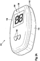
- FIGS. 1A to 1C a first, preferred embodiment of a test device 110 according to the invention for determining a blood glucose concentration is shown. It shows Figure 1A the test device 110 in the closed state, FIG. 1B the test device 110 during opening and Figure 1C the test device 110 in the open state.
- the test device 110 comprises a housing 112 with a housing lower part 114 and a cover 116 (housing upper part).
- the lower housing part 114 and cover 116 are connected to one another along a hinge 118, wherein the hinge 118 simultaneously serves to transmit power. This power transmission ensures that the force used to open the lid 116 can be used simultaneously in the housing base 114 to rotate a test strip (see below).
- the housing 112 has a closed, smooth surface.
- the cover 116 and the lower housing part 114 are adapted to one another in terms of their shape such that only a narrow parting line 120 is created, through which substantially no contaminations in the form of dirt and water can penetrate into the interior of the test device 110.
- an upwardly facing operating step 122 is formed on the lower housing part 114, which can be encompassed during the opening of the housing 112, for example with the thumb of a hand.
- a release button 124 is arranged on the operating level 122.
- This release button 124 may have purely mechanical function, in particular by opening the housing 112 is released by pressing the release button 124. Alternatively or additionally, the release button 124 may also have electrical function, for. B. by when pressing the release button 124 a Measuring electronics and / or a microcomputer in the test apparatus 110 is started or initialized.
- the user interface 126 has a display element in the form of a display 130 and a plurality of control buttons 132. For example, measurements can be started via the control buttons 132 and / or menu functions of the test device 110 can be called up. For example, analyte concentrations can be represented numerically on the display 130. Overall, the functionality of the test device 110 is comparable, for example, to known test devices which are commercially available.
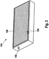
- a latch-like magazine 134 is embedded in the measuring surface 128 in the lower housing part 114.
- the magazine 134 is designed to be interchangeable and has a multiplicity of cavities 135 in which test strips 136 are received parallel to one another.
- the magazine 134 in particular the cavities 135, may additionally comprise a desiccant (in FIG. 3 not shown), which protects the recorded in the cavities 135 test strip 136 from the influence of humidity.
- An example of such a magazine 134 is in FIG. 3 shown.
- a membrane in the form of a sealing film 138 is applied.
- the magazine 134 has an axis of rotation 140 around which the individual test strips 136 are rotatably mounted.
- test strip 136 When opening the housing 112 of the test device 110 (see. FIG. 1 B) a test strip 136 is rotated about the axis of rotation 140 by means of an output device (not shown). In this case, the sealing film 138 of the associated cavity 135 is broken or pierced by the test strip edge 142 of the test strip 136. In fully unfolded state of the housing 112 (see. Figure 1C ), the test strip 136 is in an upright application and measurement position. Alternatively, other orientations of the test strip 136 for sample application and / or measurement are possible, for example, a separate application position and measurement position.
- Both the hole 144 and the notch 146 enable the test strip 136 to pivot about the axis of rotation 140 of the magazine 134 from a (horizontal) storage position to a vertical (vertical) position , see. Figure 1c ) Measuring position is rotated.
- the housing 112 of the test device 110 further includes an electronic evaluation device.
- This electronic evaluation device is used for evaluating the test strips 136 by means of an electrochemical measurement.
- evaluation electronics are known in the art.
- the evaluation electronics can also include a microcomputer, which can be operated for example via the control buttons 132.
- the microcomputer can control appropriate evaluation routines and include, for example, data storage.
- the display 130 and the control buttons 132 are integrated in the inner control surface 126 of the lid 116.
- opening the housing 112 may automatically cause the test device 110 to turn on.
- the unlocking button 124 which can also be realized as an "on / off button"
- the patient closes the housing 112 again by closing the lid 116.
- the test strip 136 is automatically swung back into its cavity 135.
- the test strip 136 may also be manually removed and disposed of.
- the test device 110 can optionally also be switched off automatically, so that the test device 110 is prevented from being switched on unintentionally. This saves in particular electrical energy.
- FIGS. 2A and 2 B is one to the FIGS. 1A to 1C alternative embodiment 110, which has similar functionality.
- a magazine 134 for example a magazine according to the embodiment in FIG FIG. 3 , taken in.
- the magazine 134 in turn has cavities 135 into which electrochemical test strips 136 are embedded.
- the test strips 136 may in turn be configured analogously to the exemplary embodiments in FIGS FIGS. 4A or 4B ,
- test device 110 may be configured such that a patient opens the housing 112 and applies a drop of blood 158 to the test strip 136. Subsequently, the housing 112 is closed again, whereby, for example automatically a measurement is started or continued or electronic measurement results are evaluated, the results can be read in turn with the housing 112 closed from the display 130.
- the dispenser 160 operates with a magazine 134, for example, as shown in FIG FIG. 3 , together.
- a magazine 134 In the magazine 134 are a plurality of test strips 136, in this embodiment, test strip 136 according to the embodiment in FIG. 4A , added.
- the test strips 136 have electrode contacts 148 at one end and an application site 150 for applying a blood drop 158 at the opposite end.
- the test strips 136 each have a hole 144, through which an axis of rotation 140 is guided.
- the lower housing part 114 of the test device 110 is designed such that it has a receptacle for mounting the ends of the rotational axis 140. This shot is in the FIGS. 5A to 5E not shown.
- the axis of rotation 140 thus represents, for example, an integral part of a magazine 134, wherein the insertion of a new magazine 134 in a housing 112 of a test device 110, the ends of the rotation axis 140 are respectively engaged or inserted into corresponding receptacles in the housing 112.
- each test strip 136 is rotatably mounted about this axis of rotation 140.
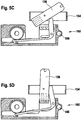
- a test strip 136 is moved from a storage position (FIG. FIG. 5A ) into a measuring position ( FIG. 5E ).
- the test strip 136 is located with the housing 112 closed (see illustration in FIG Figure 1A ) in the FIG. 5A bearing position shown, whereas when the housing 112 is open (see. Figure 1C ) the test strip 136 in the in FIG. 5E is shown measuring position.
- FIG. 5A shown storage position of the test strip 136 is received in a cavity 135.
- the test strip 136 is shown in comparison to the storage position according to FIG. 5A rotated 90 °, with the electrode contacts 148 facing down and the application point 150 facing upward.
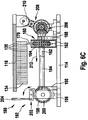
- the dispenser 160 has an output housing 162 which is disposed below the magazine 134.
- a gear 164 is rotatably mounted with a rotation axis perpendicular to the plane of the drawing. This gear 164 is driven by a hinge (not shown) through the hinge 118 of the test apparatus 110 and rotates counterclockwise when the housing 112 is opened.
- FIG. 5A illustrated rest position which represents a closed housing 112 of the test apparatus 110
- the transport arm 166 is guided via a pin 172 and a curved oblong hole 174 in the dispensing housing 162 of the dispensing device 160.
- the pressure area 170 of the transport arm 166 begins to penetrate the magazine 134 (see FIGS. 5B to 5E ).
- the pressure region 170 penetrates into exactly one cavity 135 of the magazine 134, wherein exactly one test strip 136 is pushed out of the magazine 134.
- the magazine 134 above and below each cavity 135 a perforable membrane 138 (see FIG. 3 , in the FIGS. 5A to 5E not shown). This membrane can be pierced by the edges of the test strip 136 and / or the print area 170 of the transport arm 166.
- the transport arm 166 through the gear 164 via the drive portion 168 in the FIGS. 5A to 5E moved to the right, causing the printing area 170 moves up into the magazine 134.
- the magazine 134 is such mounted above the dispensing device 160 such that the pressure region 170 acts on the test strip 136 to the right of the axis of rotation 140.
- the test strip 136 in the illustrations according to the FIGS. 5A to 5E turned counterclockwise.
- the output device 160 in this embodiment according to the FIGS. 5A to 5E Contacts 176 for contacting the test strip 136 on. These contacts 136 are connected to a measuring electronics of the test device 110.
- This measuring electronics which is not shown, enables the evaluation of a test strip 136 using electrochemical measuring methods known to the person skilled in the art.
- this measuring electronics may include electronics for performing a current-voltage measurement or a capacitive measurement.
- the contacts 176 are fixed to the output housing 162 of the dispenser 160 such that the contacts 176 in the in FIG. 5E shown measuring position contact the electrode contacts 148 of the test strip 136.
- the contacts 176 may have a corresponding clamping device into which the test strip 136 is pressed by the dispensing device 160, in particular by the transport arm 166. In this way, a secure and reliable electrical contact between electrode contacts 148 and contacts 176 can be made.
- the dispenser 160 shown provides a mechanism for dispensing exactly one test strip 136 from the magazine 134. Depending on the positioning of the dispensing device 160 below a certain cavity 135 of the magazine 134 just that test strip 136 in the measuring position (see FIG. 5E ), which is located in the corresponding cavity 135.
- the test device 110 may include a mechanism that includes the selection of a specific cavity 135 of the magazine 134.
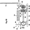
- An example of such a selector 180 is shown in FIGS FIGS. 6A to 6D shown schematically in different views. It shows FIG. 6A a partial perspective view with the lid closed 116, FIG. 6B a partial perspective view with lid open 116, FIG. 6C a side view with closed lid 116 and FIG. 6C a side view with the lid open.
- FIGS. 6A to 6C should be explained in synopsis.
- the dispenser 160 according to the above in the FIGS. 5A to 5E described embodiment is mounted on two shafts 182, 184, namely a drive shaft 182 and a sliding shaft 184, which are components of the selector 180.
- the drive shaft 182 is connected to the gear 164 of the output device 160 and drives it.
- the sliding shaft 184 passes through a corresponding Gleitwellenbohrung 186 in the output housing 162, so that the output device 160 can slide on the sliding shaft 184.
- a lid-side (ie in the FIGS. 6A to 6D Right) stop position of the dispenser 160 is determined by a fixed to the housing base 114 stop 188, which also holds the lid-side end of the sliding shaft 184 at the same time.
- the opposite end of the slide shaft 184 is supported in a bracket 190.
- the selection device 180 has a drive unit 192.
- the drive unit 192 in turn has a transverse shaft 194 which is mounted on two side brackets 196 and which extends perpendicular to the shafts 182, 184. On the cross shaft 194 two drums 198 and a balance 200 are attached.
- the transverse shaft 194 is biased by a spring (not shown).
- the drive unit 192 has a rocker 202 with a release lever 204. This release lever 204 is connected to the release button 124 (cf. Figure 1A ) connected. If the release lever 204 is actuated, the rocker 202 releases the balance 200 in the short term, so that it, driven by the spring, can move straight around a catch (corresponding to a tooth on the balance 200).
- drums 198 a (not shown in the figures) spring band is wound, which in turn is connected to the output device 160.
- the drums 198 also rotate, causing the spring band to hit the drums is wound up.
- the output device 160 in the direction of movement 212, ie in the FIGS. 6A to 6D to the left, moved.
- Per catch of the balance 200 so per actuation of the trigger lever 204, there is a defined movement of the dispenser 160 by one step.
- the magazine 134 is disposed above the dispenser 160.
- the balance 200 and the translation by the drums 198 are dimensioned such that a movement step just means the positioning about a cavity 135 forward.
- the dispenser 160 is advanced by a cavity 135.
- the lid 116 Only by pressing the release button 124, the lid 116 is released and can, driven by the spring force, open. However, when the cover 116 is opened, the drive shaft 182, which in turn drives the gear wheel 164 of the dispensing device 160, is rotated via the angular gear 206, whereby a test strip 136 is output from the magazine 134 via the transport arm 166.
- an output process of a test strip 136 from the magazine 134 so after the following steps designed.
- a user actuates the release button 124 of the housing 112.
- the output device 160 is further positioned by exactly one cavity 135 via the release lever 204 and the balance 200.
- the lid 116 is released and works, driven by spring force on.
- the gear 164 of the output device 160 is actuated via the drive shaft 182, whereby in turn the output device 160 by means of the transport arm 166 exactly one test strip 136 in the in FIG. 5E conveyed shown application and measurement position, so that a measurement can be performed.
Description
Die Erfindung betrifft eine Testvorrichtung, insbesondere eine tragbare Testvorrichtung, zur Bestimmung mindestens einer Analytkonzentration in einer Probe mittels eines Testelements. Weiterhin betrifft die Erfindung ein Testelement zur Bestimmung mindestens einer Analytkonzentration in einer Probe unter Verwendung einer erfindungsgemäßen Testvorrichtung. Derartige Testvorrichtungen und Testelemente werden insbesondere zur Messung von Blutglukosekonzentrationen eingesetzt.The invention relates to a test device, in particular a portable test device, for determining at least one analyte concentration in a sample by means of a test element. Furthermore, the invention relates to a test element for determining at least one analyte concentration in a sample using a test device according to the invention. Such test devices and test elements are used in particular for the measurement of blood glucose concentrations.
Die Überwachung der Blutglukosekonzentration ist für Diabetiker ein essentieller Bestandteil des Tagesablaufs. Dabei muss die Blutglukosekonzentration schnell und zuverlässig mehrmals am Tag bestimmt werden, um gegebenenfalls entsprechende medizinische Maßnahmen ergreifen zu können. Um den Tagesablauf des Diabetikers nicht mehr als nötig einzuschränken, werden dabei häufig entsprechende mobile Geräte eingesetzt, welche einfach zu transportieren und zu handhaben sein sollten, so dass die Messung der Blutglukosekonzentration beispielsweise am Arbeitsplatz oder auch in der Freizeit erfolgen kann.The monitoring of the blood glucose concentration is an essential part of the daily routine for diabetics. The blood glucose concentration must be determined quickly and reliably several times a day in order to be able to take appropriate medical measures if necessary. In order to limit the daily routine of the diabetic no more than necessary, often corresponding mobile devices are used, which should be easy to transport and handle, so that the measurement of blood glucose concentration, for example, at work or in the leisure can take place.
Derzeit sind verschiedene mobile Geräte auf dem Markt, welche teilweise nach unterschiedlichen Messmethoden funktionieren. Dabei kommen verschiedene Diagnoseverfahren zum Einsatz, beispielsweise optische oder auch elektrochemische Messverfahren.At present, there are several mobile devices on the market, some of which work according to different measurement methods. Various diagnostic methods are used, for example optical or even electrochemical measuring methods.
Ein Beispiel eines häufig eingesetzten Messverfahrens nutzt eine spezielle Art elektrochemischer Teststreifen. Diese Teststreifen sind beispielsweise so aufgebaut, dass eine vorgegebene Blutmenge über ein Kapillarensystem auf dem Teststreifen zu einem Elektrodensystem geführt wird. Für moderne Teststreifen genügt dabei eine Blutmenge von ca. 1,5 µl, teilweise auch Blutmengen unter 1 µl. Bei dem Elektrodensystem kann es sich z. B. um Goldelektroden handeln, welche mit einer Beschichtung versehen sind. Die Beschichtung enthält zumeist verschiedene Enzyme und so genannte Mediatoren und bewirkt, dass sich innerhalb der Probe an den Elektroden Ladungsträger (beispielsweise in Form von Redox-Molekülen) bilden, deren Konzentration abhängig ist von der Blutglukosekonzentration. Die Konzentration dieser Ladungsträger kann mittels der Goldelektroden und einem geeigneten Messsystem, beispielsweise mittels einer Strom-Spannungs-Messung bestimmt werden, so dass daraus schließlich auf die Blutglukosekonzentration zurückgerechnet werden kann. Ein Beispiel derartiger elektrochemischer Teststreifen ist in
Alternativ zu dem beschriebenen elektrochemischen Messverfahren lassen sich auch andere Messprinzipien einsetzen. So beschreibt beispielsweise die
Die Teststreifen bilden somit ein wesentliches Element portabler Diagnosesysteme. Typischerweise werden von einem Diabetiker ca. 5 bis 7 derartiger Teststreifen pro Tag benötigt. Essentiell ist dabei, dass die Teststreifen sauber und trocken aufbewahrt werden, um nicht durch eine entsprechende Verschmutzung bzw. Einwirkung von Feuchtigkeit die Messung der Blutglukosekonzentration zu verfälschen.The test strips thus form an essential element of portable diagnostic systems. Typically, about 5 to 7 such test strips per day are needed by a diabetic. It is essential that the test strips are kept clean and dry in order not to falsify the measurement of the blood glucose concentration by appropriate contamination or exposure to moisture.
Zu diesem Zweck werden die Teststreifen üblicherweise in entsprechenden Behältnissen aufbewahrt, um anschließend vom Benutzer für eine Messung dem Teststreifenbehältnis entnommen und in ein entsprechendes Messgerät eingegeben zu werden. Derartige Messgeräte, beispielsweise Messgeräte für eine elektrochemische Bestimmung der Blutglukosekonzentration, sind dem Fachmann bekannt und werden beispielsweise in
Die aus dem Stand der Technik bekannten Messsysteme, bei welchen eine Blutglukosekonzentration mittels eines einzelnen Teststreifens bestimmt wird (Einzelstreifensysteme), wobei jeweils ein einzelner Teststreifen für eine Messung in das Gerät eingegeben werden muss, weisen jedoch in der Praxis zahlreiche Nachteile auf. So erfordern derartige Systeme zahlreiche Handhabungsschritte durch den Nutzer bzw. Patienten. Ein Teststreifen muss einer entsprechenden Aufbewahrungsvorrichtung (z. B. einer Teststreifendose) entnommen werden und manuell in ein Messgerät eingefügt werden. So muss ein entsprechender Teststreifen für derartige Einzelstreifensysteme für eine sichere Handhabung durch einen Patienten, insbesondere durch ältere Patienten oder Kinder, vergleichsweise groß ausgestaltet sein, um zu verhindern, dass der Teststreifen den Fingern des Patienten entgleitet und für eine Messung unbrauchbar wird. Eine erhöhte Größe der Teststreifen trägt jedoch dazu bei, dass der Platzbedarf der Messsysteme steigt und weniger Teststreifen in einem entsprechenden Behältnis untergebracht werden können. Außerdem steigen durch diesen erhöhten Platzbedarf die Materialkosten der Messsysteme.However, measuring systems known from the prior art, in which a blood glucose concentration is determined by means of a single test strip (single-strip systems), wherein in each case a single test strip for a measurement must be entered into the device, have numerous disadvantages in practice. Thus, such systems require numerous handling steps by the user or patient. A test strip must be taken from a corresponding storage device (eg, a test strip box) and inserted manually into a meter. Thus, a corresponding test strip for such single-strip systems for safe handling by a patient, in particular by elderly patients or children, must be made comparatively large in order to prevent the test strip from slipping off the patient's fingers and becoming unusable for a measurement. An increased size of the test strips, however, contributes to the fact that the space requirement of the measuring systems increases and fewer test strips can be accommodated in a corresponding container. In addition, this increased space requirement increases the material costs of the measuring systems.
Weiterhin ist die manuelle Handhabung der Teststreifen mit dem Nachteil einer erhöhten Verschmutzungsgefahr der Teststreifen verbunden. So kann eine manuelle Entnahme der Teststreifen aus einem Teststreifenbehältnis zu einer Beaufschlagung der Teststreifen mit Fingerschweiß oder anderen Verschmutzungen führen, welche eine entsprechende Messung beeinträchtigen könnten. Ein weiterer erheblicher Nachteil besteht darin, dass bei jedem Öffnen des Teststreifenbehältnisses die im Teststreifenbehältnis verbleibenden Teststreifen mit Luftfeuchtigkeit beaufschlagt werden, so dass später verwendete Teststreifen aus einem Teststreifenbehältnis möglicherweise andere Eigenschaften aufweisen als die zuerst entnommenen Teststreifen.Furthermore, the manual handling of the test strips is associated with the disadvantage of an increased risk of contamination of the test strips. Thus, a manual removal of the test strips from a test strip container can lead to an exposure of the test strips with finger sweat or other contaminants, which could affect a corresponding measurement. Another significant disadvantage is that each time the test strip container is opened, the test strips remaining in the test strip container are exposed to atmospheric moisture, so that later used Test strips from a test strip container may have different properties than the test strips first removed.
Um die Nachteile derartiger Einzelstreifensysteme zu vermeiden, wurden integrierte Systeme entwickelt, insbesondere Systeme, bei welchen neben einer Messvorrichtung auch ein Magazin für Teststreifen integriert ist. Die Systeme können derart ausgestaltet sein, dass jeweils ein Teststreifen für eine Messung aus dem Magazin in eine Messposition ausgegeben wird. Nach Beaufschlagung mit der entsprechenden Probe, beispielsweise einem Blutstropfen, wird dann unmittelbar die Messung durchgeführt.In order to avoid the disadvantages of such single-strip systems, integrated systems have been developed, in particular systems in which a magazine for test strips is integrated in addition to a measuring device. The systems can be configured such that in each case a test strip for a measurement is output from the magazine into a measuring position. After exposure to the corresponding sample, for example a drop of blood, the measurement is then carried out immediately.
Ein Beispiel eines derartigen integrierten Systems ist in der
Integrierte Systeme weisen gegenüber herkömmlichen Einzelstreifensystemen erhebliche Vorteile auf. So wird die Anzahl der erforderlichen Handhabungsschritte für eine Messung reduziert, und es lassen sich auch kleine, kostengünstige Testelemente einsetzen. Auch wird die Beaufschlagung der Testelemente, insbesondere der Teststreifen, mit Feuchtigkeit und Verschmutzungen erheblich reduziert.Integrated systems have significant advantages over conventional single strip systems. Thus, the number of required handling steps for a measurement is reduced, and it can be used even small, inexpensive test elements. Also, the exposure of the test elements, in particular the test strips, with moisture and dirt is significantly reduced.
Die aus dem Stand der Technik bekannten integrierten Systeme weisen jedoch auch Nachteile auf, insbesondere Nachteile, welche den Einsatz als portable Geräte stören und die Akzeptanz durch einen Patienten verringern. Ein wesentlicher Nachteil besteht darin, dass die Integration der Systeme zu vergleichsweise großen Baugrößen der Geräte führt.. So sind für viele integrierte Systeme beispielsweise vergleichsweise voluminöse Federsysteme erforderlich, welche einen entsprechenden Transport der Teststreifensysteme ermöglichen. Zudem werden integrierte Systeme häufig elektromotorisch angetrieben, was zu einem zusätzlichen Platzbedarf führt. Integrierte Systeme, welche nicht elektromotorisch angetrieben werden, erfordern hingegen zusätzliche Spannvorrichtungen, was wiederum eine Handhabung insbesondere durch ältere Patienten oder Kinder in vielen Fällen stört. Zudem werden durch elektromotorische Antriebe oder komplexe manuelle Antriebe die Herstellkosten der Systeme stark erhöht. Elektrisch angetriebene Systeme weisen zusätzlich den Nachteil auf, dass für die Elektromotoren leistungsfähige Batterien erforderlich sind, welche teuer sind und oft gewechselt werden müssen. Diese Batterien führen außerdem zu einer zusätzlichen Erhöhung des Bauvolumens. Ein weiterer Nachteil der komplex ausgestalteten integrierten Systeme, welche aus dem Stand der Technik bekannt sind, besteht darin, dass derartige Systeme häufig empfindliche Bauteile auf ihren Oberflächen aufweisen, welche beispielsweise bei einem Transport in einer Tasche leicht mechanisch beschädigt werden können, welche ein Eindringen von Feuchtigkeit in die Geräte ermöglichen, und/oder welche durch eine Verschmutzung in ihrer Funktionalität beeinträchtigt werden können.However, the known from the prior art integrated systems also have disadvantages, in particular disadvantages, which interfere with the use as portable devices and reduce the acceptance by a patient. A major disadvantage is that the integration of the systems leads to comparatively large sizes of the devices. Thus, for example, comparatively bulky spring systems are required for many integrated systems, which enable appropriate transport of the test strip systems. In addition, integrated systems are often driven by an electric motor, which leads to an additional space requirement. By contrast, integrated systems which are not driven by an electric motor require additional tensioning devices, which in turn can be handled in particular by elderly patients or children in many Cases disturbs. In addition, the production costs of the systems are greatly increased by electric motor drives or complex manual drives. Electrically powered systems also have the disadvantage that powerful batteries are required for the electric motors, which are expensive and often have to be changed. These batteries also lead to an additional increase in construction volume. Another disadvantage of the complex integrated systems, which are known from the prior art, is that such systems often have sensitive components on their surfaces, which can be easily mechanically damaged, for example when transported in a bag, which is an intrusion of Allow moisture in the equipment, and / or which may be impaired by pollution in their functionality.
Aufgabe der vorliegenden Erfindung ist es, eine Testvorrichtung zur Bestimmung mindestens einer Analytkonzentration in einer Probe, insbesondere einer flüssigen Probe, mittels mindestens eines Testelements bereitzustellen, welche die Nachteile der aus dem Stand der Technik bekannten Testvorrichtungen vermeidet. Weiterhin soll ein Magazin mit Testelementen bereitgestellt werden, welches in der erfindungsgemäßen Testvorrichtung eingesetzt werden kann.The object of the present invention is to provide a test device for determining at least one analyte concentration in a sample, in particular a liquid sample, by means of at least one test element which avoids the disadvantages of the test devices known from the prior art. Furthermore, a magazine with test elements is to be provided, which can be used in the test device according to the invention.
Diese Aufgabe wird durch die Erfindung mit den Merkmalen des unabhängigen Anspruchs gelöst. Vorteilhafte Weiterbildungen der Erfindung sind in den Unteransprüchen gekennzeichnet. Der Wortlaut sämtlicher Ansprüche wird hiermit durch Bezugnahme zum Inhalt dieser Beschreibung gemacht.This object is achieved by the invention with the features of the independent claim. Advantageous developments of the invention are characterized in the subclaims. The wording of all claims is hereby incorporated by reference into the content of this specification.
Es wird eine Testvorrichtung zur Bestimmung mindestens einer Analytkonzentration in einer Probe mittels eines Testelements vorgeschlagen. Insbesondere kann es sich dabei um eine Glukosemessung, insbesondere eine Blutglukosemessung, und/oder eine Cholesterinmessung und/oder eine Koagulationsmessung handeln. Alternativ oder zusätzlich können jedoch auch andere Analytkonzentrationen ermittelt werden oder entsprechende andere Analysen durchgeführt werden, beispielsweise pH-Messungen oder ähnliche chemische Analysen oder Messungen. Auch können beispielsweise immunologische Messungen oder ähnliche Messungen mit der Testvorrichtung durchgeführt werden. Bei der Probe soll es sich insbesondere um eine flüssige Probe, beispielsweise Blut, Urin, Speichel oder Stuhl, handeln. Es sind jedoch auch andere Arten von Proben denkbar, beispielsweise gasförmige Proben. Weiterhin kann anstelle einer Analytkonzentration auch lediglich auf die Anwesenheit oder Nicht-Anwesenheit eines Analyten geschlossen werden, was erfindungsgemäß mit umfasst sein soll.A test device for determining at least one analyte concentration in a sample by means of a test element is proposed. In particular, this may be a glucose measurement, in particular a blood glucose measurement, and / or a cholesterol measurement and / or a coagulation measurement. Alternatively or additionally, however, other analyte concentrations can also be determined or corresponding other analyzes can be carried out, for example pH measurements or similar chemical analyzes or measurements. Also, for example, immunological measurements or similar measurements can be made with the test device. At the rehearsal it should in particular a liquid sample, for example blood, urine, saliva or stool act. However, other types of samples are conceivable, for example gaseous samples. Furthermore, instead of an analyte concentration, it is also possible to conclude only the presence or absence of an analyte, which should be included according to the invention.
Die Testvorrichtung weist ein Gehäuse auf, welches einen geschlossenen Zustand und einen geöffneten Zustand aufweist. Das Gehäuse kann insbesondere derart ausgestaltet sein, dass das Gehäuse manuell durch einen Benutzer zu öffnen ist. Insbesondere kann das Gehäuse aufschiebbar oder aufklappbar ausgestaltet sein. Beispielsweise kann das Gehäuse eine im Wesentliche quaderförmige Form aufweisen mit einer Klappachse, wobei das Gehäuse entlang der Klappachse aufgeklappt werden kann, so dass ein Gehäuseunterteil und ein Gehäuseoberteil im aufgeklappten Zustand winklig zueinander stehen, beispielsweise in einem rechten Winkel. Im geschlossenen Zustand liegen Gehäuseunterteil und Gehäuseoberteil aufeinander, wobei jeweils die Flächen, entlang derer Gehäuseunterteil und Gehäuseoberteil aneinander anliegen, von außen nicht mehr zugänglich sind. Dies kann beispielsweise so erfolgen, dass die Flächen, entlang derer Gehäuseunterteil und Gehäuseoberteil aneinander anliegen, im geschlossenen Zustand des Gehäuses durch das Gehäuse abgedichtet sind, beispielsweise um diese Flächen und Elemente, die auf und/oder in diesen Flächen angeordnet sind (z. B. Displays, Bedienelemente, Teststreifen etc.), vor Umwelteinflüssen, z. B. Luftfeuchtigkeit, Schmutz oder mechanischen Einwirkungen, zu schützen. Derartige Systeme sind aus dem Stand der Technik beispielsweise für Mobiltelefone bekannt. Es sind jedoch auch andere erfindungsgemäße Öffnungsvorrichtungen denkbar, beispielsweise Schiebevorrichtungen.The test device has a housing which has a closed state and an opened state. The housing may in particular be designed such that the housing can be opened manually by a user. In particular, the housing can be configured pushed or hinged. For example, the housing may have a substantially cuboid shape with a folding axis, wherein the housing can be opened along the folding axis, so that a lower housing part and a housing upper part in the unfolded state are at an angle to each other, for example, at a right angle. In the closed state, the lower housing part and the upper housing part lie against one another, with the surfaces along which the lower housing part and the upper housing part rest against each other being inaccessible from the outside. This can be done, for example, that the surfaces along which the lower housing part and the upper housing part abut each other, are sealed in the closed state of the housing by the housing, for example around these surfaces and elements which are arranged on and / or in these surfaces (eg Displays, operating elements, test strips, etc.), against environmental influences, eg. As humidity, dirt or mechanical effects to protect. Such systems are known from the prior art, for example for mobile phones. However, other opening devices according to the invention are also conceivable, for example sliding devices.
Das erfindungsgemäße Merkmal, dass das Gehäuse geöffnet werden kann, stellt einen erheblichen Vorteil gegenüber bekannten Systemen dar. Insbesondere die Weiterbildung, bei welcher das Gehäuse aufgeklappt werden kann, ermöglicht es, empfindliche Komponenten, welche einem Benutzer zugänglich sein sollen, in einem Bereich des Gehäuses unterzubringen, welcher nur im aufgeklappten bzw. geöffneten Zustand des Gehäuses zugänglich ist.The feature according to the invention that the housing can be opened, represents a considerable advantage over known systems. In particular, the development in which the housing can be opened, allows sensitive components which are to be accessible to a user, in a region of the housing accommodate, which is accessible only in the unfolded or opened state of the housing.
Weiterhin weist die Testvorrichtung eine Lagervorrichtung zur Aufnahme von Testelementen auf, wobei die Lagervorrichtung mindestens eine Lagerposition für Testelemente aufweist. Beispielsweise kann die Lagervorrichtung derart ausgestaltet sein, dass mehrere Testelemente vorgesehen sind, welche jeweils einzeln in jeweils einer Kavität der Lagervorrichtung gelagert sind. Im Gegensatz zu vielen aus dem Stand der Technik bekannten Vorrichtungen, beispielsweise der aus der
Weiterhin weist die erfindungsgemäße Testvorrichtung eine Messvorrichtung auf. Die Messvorrichtung ist derart ausgestaltet, dass mittels der Testelemente die mindestens eine Analytkonzentration bestimmt werden kann. Derartige Messvorrichtungen sind dem Fachmann bekannt und sollen daher an dieser Stelle nicht weiter beschrieben werden. Insbesondere hängt die Art der Messvorrichtung von der Art des verwendeten Testelements ab, dessen mögliche Ausgestaltung unten näher beschrieben werden soll. Beispielsweise kann die mindestens eine Messposition Kontakte zur Kontaktierung des mindestens einen Testelements aufweisen.Furthermore, the test device according to the invention has a measuring device. The measuring device is designed such that the at least one analyte concentration can be determined by means of the test elements. Such measuring devices are known in the art and therefore should not be further described at this point. In particular, the type of measuring device depends on the type of test element used, the possible embodiment of which is to be described in greater detail below. For example, the at least one measuring position may have contacts for contacting the at least one test element.
Weiterhin weist die Testvorrichtung eine Ausgabevorrichtung auf. Die Ausgabevorrichtung ist mit Mitteln ausgestattet, welche eine Beförderung der Testelemente von der mindestens einen Lagerposition in mindestens eine Messposition bei Öffnen des Gehäuses ermöglichen. Unter einem "Öffnen" des Gehäuses kann dabei insbesondere ein Zugänglichmachen von im geschlossenen Zustand verborgenen Komponenten, beispielsweise von Flächen, entlang derer Gehäuseunterteil und Gehäuseoberteil aneinander anliegen, sowie von auf diesen Flächen angeordneten Bedienelementen (Displays, Bedienknöpfen, Teststreifenmagazin) verstanden werden. Beispielsweise kann hierunter ein Aufschieben oder Aufklappen des Gehäuses verstanden werden. Vorzugsweise wird dabei auch eine Teststreifenausgabe zugänglich, beispielsweise indem beim Öffnen des Gehäuses ein Ausgabeschlitz oder ähnliches freigegeben wird. Auch eine andere Art von "Zugänglichmachen von Komponenten" kann unter dem Begriff "Öffnen" subsumiert werden.Furthermore, the test device has an output device. The dispensing device is equipped with means which allow a transport of the test elements from the at least one storage position into at least one measuring position when the housing is opened. In this context, "opening" of the housing can in particular mean the accessibility of components concealed in the closed state, for example surfaces along which housing lower part and housing upper part abut one another, as well as operating elements arranged on these surfaces (displays, control buttons, test strip magazine). For example, this can be understood as a sliding or unfolding of the housing. Preferably, a test strip output is also accessible, for example by releasing an output slot or the like when opening the housing. Another type of "making components available" can also be subsumed under the term "opening".
Insbesondere kann die Beförderung des mindestens einen Testelements von der mindestens einen Lagerposition in die mindestens eine Messposition durch das Öffnen des Gehäuses ausgelöst und/oder bewirkt werden. Beispielsweise kann der Kraftaufwand, welcher für einen Benutzer zum Öffnen des Gehäuses erforderlich ist, genutzt werden, um die Beförderung des Testelements zu bewerkstelligen. Beispielsweise kann die Kraft, welche beim Öffnen des Gehäuses auf das Gehäuse ausgeübt wird, mittels einer entsprechenden mechanischen Vorrichtung, beispielsweise einer Hebelvorrichtung, auf das mindestens eine Testelement übertragen werden.In particular, the transport of the at least one test element from the at least one storage position into the at least one measuring position can be triggered and / or effected by opening the housing. For example, the amount of force required for a user to open the housing can be used to accomplish the carriage of the test element. For example, the force which is exerted on the housing when the housing is opened can be transmitted to the at least one test element by means of a corresponding mechanical device, for example a lever device.
Dabei ist es besonders vorteilhaft, wenn die Beförderung des mindestens einen Testelemente durch die Ausgabevorrichtung eine Drehbewegung des Testelements um eine Drehachse umfasst. Insbesondere kann das mindestens eine Testelement eine Längserstreckung haben, beispielsweise eine Längsachse eines Teststreifens, wobei vorteilhafterweise die Drehung des Testelements bei der Beförderung von der mindestens einen Lagerposition in die mindestens eine Messposition um eine Drehachse senkrecht zur Längsachse des Testelements erfolgt. So kann die Ausgabevorrichtung eine derartige Drehachse aufweisen. Beispielsweise kann diese Drehachse das mindestens eine Testelement durchsetzen.It is particularly advantageous if the transport of the at least one test element by the output device comprises a rotational movement of the test element about an axis of rotation. In particular, the at least one test element can have a longitudinal extent, for example a longitudinal axis of a test strip, wherein advantageously the rotation of the test element takes place during the transport from the at least one storage position into the at least one measurement position about an axis of rotation perpendicular to the longitudinal axis of the test element. Thus, the output device may have such a rotation axis. For example, this axis of rotation can enforce the at least one test element.
Alternativ oder zusätzlich kann die Beförderung des Testelements von der mindestens einen Lagerposition in die mindestens eine Messposition auch durch eine anders ausgestaltete Bewegung erfolgen, beispielsweise eine Translationsbewegung. So kann beispielsweise beim Öffnen des Gehäuses ein Teststreifen in eine Messposition geschoben werden. Auch eine Kombination von Bewegungsarten, beispielsweise eine Translations-Rotationsbewegung, ist möglich.Alternatively or additionally, the transport of the test element from the at least one storage position into the at least one measuring position can also be effected by a differently configured movement, for example a translational movement. For example, when opening the housing, a test strip can be pushed into a measuring position. A combination of movement types, for example, a translational rotational movement, is possible.
Die erfindungsgemäße Testvorrichtung weist gegenüber anderen integrierten Testvorrichtungen, welche aus dem Stand der Technik bekannt sind, zahlreiche Vorteile auf. Insbesondere die Öffnungsfunktion des Gehäuses, beispielsweise das Aufklappen des Gehäuses, ermöglicht es, transportable Testvorrichtungen zu gestalten, welche sich durch äußerste Robustheit auszeichnen. So kann das Gehäuse derart ausgestaltet sein, dass im geschlossenen Zustand des Gehäuses von außen lediglich unempfindliche Komponenten der Testvorrichtung zugänglich sind. Beispielsweise kann das Gehäuse auf seiner Außenseite mit einer glatten, schmutzabweisenden Oberfläche ausgestaltet sein, welche ein Eindringen von Schmutz und Feuchtigkeit in die Testvorrichtung verhindert. Alternativ können jedoch auch einzelne Bedienelemente auf der äußeren Oberfläche des Gehäuses angeordnet sein, beispielsweise einzelne Bedienknöpfe oder Anzeigeelemente. Von Vorteil ist es jedoch, wenn die wesentlichen und insbesondere die empfindlichen Funktionselemente der Testvorrichtung erst im geöffneten Zustand des Gehäuses zugänglich sind. Insbesondere kann die Testvorrichtung derart ausgestaltet sein, dass Bedienknöpfe, Bedientasten, Anzeigeelemente und weitere Funktionselemente der Testvorrichtung im aufgeklappten Zustand zugänglich sind.The test device according to the invention has numerous advantages over other integrated test devices known in the art. In particular, the opening function of the housing, for example, the unfolding of the housing, makes it possible to design portable test devices, which are characterized by utmost robustness. Thus, the housing may be configured such that in the closed state of the housing from the outside only insensitive components of the test device are accessible. For example, the housing can be designed on its outside with a smooth, dirt-repellent surface, which prevents penetration of dirt and moisture into the test device. Alternatively, however, individual controls on the outer surface of the housing be arranged, for example, individual control buttons or display elements. It is advantageous, however, if the essential and in particular the sensitive functional elements of the test device are accessible only when the housing is open. In particular, the test device can be configured such that control buttons, control buttons, display elements and other functional elements of the test device are accessible in the unfolded state.
Die Testvorrichtung bietet weiterhin einen hohen Grad an Diskretion, da die Testvorrichtung flach ausgestaltet werden kann und somit unauffällig getragen werden kann. Ein störendes Motor- oder Getriebegeräusch tritt bei der Benutzung der Testvorrichtung nicht auf, da auf einen Elektromotor verzichtet werden kann. Die Systemkosten der Testvorrichtung sind vergleichsweise gering, da auf kostenträchtige Bauteile, wie z. B. Motoren, große Batterien etc. verzichtet werden kann. Auch die Materialkosten, insbesondere für Verbrauchsmaterial, sind vergleichsweise gering, da kleinere Testelemente eingesetzt werden können.The test device also offers a high degree of discretion, since the test device can be designed flat and thus can be carried inconspicuously. An annoying engine or transmission noise does not occur when using the test device, as can be dispensed with an electric motor. The system cost of the test device are relatively low, as costly components such. As motors, large batteries, etc. can be dispensed with. Also, the material costs, especially for consumables, are relatively low, since smaller test elements can be used.
Weiterhin ist durch die erfindungsgemäße Ausgestaltung der Testvorrichtung die Handhabungssicherheit gegenüber aus dem Stand der Technik bekannten integrierten Systemen deutlich erhöht. Für die Vorbereitung einer Bestimmung einer Analytkonzentration, beispielsweise einer Blutglukosekonzentrationsmessung, ist nunmehr lediglich ein Öffnen, beispielsweise ein Aufklappen, der Testvorrichtung erforderlich. Ein Spannen einer Transportvorrichtung oder ein Betätigen eines Elektromotors durch einen entsprechenden Knopf ist nicht mehr erforderlich. Somit ist insbesondere sichergestellt, dass auch Patienten mit eingeschränkten motorischen Fähigkeiten, insbesondere ältere Patienten oder Kinder, die Testvorrichtung sicher handhaben können.Furthermore, the handling security against known from the prior art integrated systems is significantly increased by the inventive design of the test device. For the preparation of a determination of an analyte concentration, for example a blood glucose concentration measurement, now only an opening, for example a folding, of the test device is required. A tensioning of a transport device or an actuation of an electric motor by a corresponding button is no longer necessary. Thus, it is particularly ensured that patients with limited motor skills, especially elderly patients or children, can handle the test device safely.
Ein weiterer erheblicher Vorteil der erfindungsgemäßen Ausgestaltung der Testvorrichtung, besteht darin, dass das Bauvolumen derartiger Testvorrichtungen gegenüber bekannten Testvorrichtungen erheblich verringert werden kann. Für eine erfindungsgemäße Testvorrichtung sind weder aufwändige und kostenträchtige Elektromotoren mit voluminösen und teuren Batterien erforderlich, noch ist eine komplexe und voluminöse Spannvorrichtung bzw. Transportvorrichtung für Testelemente nötig. Insbesondere die Ausgestaltung, bei welcher ein Testelement um eine Achse rotiert wird, um das Testelement von der Lagerposition in die Messposition zu bringen, ermöglicht eine platzsparende Realisierung der Testvorrichtung. Insgesamt ist also festzustellen, dass die erfindungsgemäße Testvorrichtung sich in hervorragender Weise für den Einsatz als robustes, einfach zu handhabendes und kostengünstiges mobiles Gerät handelt, welches auch für Patienten mit eingeschränkten motorischen Fähigkeiten leicht handhabbar ist. Dies fördert den so genannten "Home-Care-Gedanken" und verringert Kosten des Gesundheitssystems.Another significant advantage of the embodiment of the test device according to the invention is that the construction volume of such test devices can be considerably reduced compared to known test devices. For a test device according to the invention neither consuming and costly electric motors with bulky and expensive batteries are required, nor is a complex and bulky tensioning device or transport device for test elements necessary. In particular, the embodiment in which a test element is rotated about an axis in order to bring the test element from the storage position to the measurement position, allows a space-saving realization of the test device. Overall, it should be noted that the test device according to the invention is outstanding for use as rugged, easy-to-use and cost-effective mobile device, which is also easy to handle for patients with limited motor skills. This promotes the so-called "home-care thought" and reduces the costs of the health system.
Die Lagervorrichtung weist ein Magazin auf. Beispielsweise kann es sich dabei um ein auswechselbares Magazin handeln, wie es beispielsweise im Rahmen des nebengeordneten Anspruchs 13 separat beansprucht wird. Derartige Magazine können beispielsweise vom Patienten über eine Apotheke oder einen medizinischen Versandhandel bezogen und jeweils in die Testvorrichtung eingesetzt werden. Dabei kann es sich um Einwegmagazine oder auch um wiederverwendbare Magazine handeln. In ein auswechselbares Magazin kann beispielsweise auch ein elektronischer Speicher oder eine andere Art von Informationsträger integriert sein, so dass beim Einlegen eines neuen Magazins in die Testvorrichtung auch chargenspezifische Informationen über die in dem Magazin enthaltenen Testelemente in die Testvorrichtung übertragen werden können. Derartige so genannte "Non-evident-coding"-Systeme sind aus dem Stand der Technik bekannt.The storage device has a magazine. For example, it may be a replaceable magazine, as claimed separately, for example in the context of the independent claim 13. Such magazines can for example be obtained from the patient via a pharmacy or a medical mail-order company and used in each case in the test device. These can be disposable magazines or reusable magazines. In an exchangeable magazine, for example, an electronic memory or another type of information carrier can be integrated, so that batch-specific information about the test elements contained in the magazine can be transferred to the test device when inserting a new magazine in the test device. Such so-called "non-evident coding" systems are known from the prior art.
Von besonderem Vorteil ist es, wenn die Lagervorrichtung, beispielsweise das Magazin, eine perforierbare Membran, beispielsweise eine Folie, zum Schutz des mindestens einen Testelements gegen Luftfeuchtigkeit und Schmutz (Versiegelung) aufweist. Diese Weiterbildung der Erfindung ist insbesondere von Vorteil in Kombination mit der erfindungsgemäßen Ausgestaltung der Erfindung, bei welcher die Lagervorrichtung für jedes Testelement eine separate Kavität aufweist. So kann jede Kavität durch eine derartige perforierbare Membran abgeschlossen sein. Beispielsweise kann die Ausgabevorrichtung und/oder das mindestens eine Testelement derart ausgestaltet sein, dass bei der Beförderung des mindestens einen Testelements von der mindestens einen Lagerposition in die mindestens eine Messposition beim Öffnen des Gehäuses die Membran perforiert wird. Beispielsweise kann zu diesem Zweck das mindestens eine Testelement eine scharfe Kante oder Ecke aufweisen. Insbesondere kann die Perforation durch eine Drehbewegung des mindestens einen Testelements erfolgen, bei welcher beispielsweise eine scharfe Ecke des mindestens einen Testelements gegen die Membran gepresst wird, so lange, bis diese perforiert wird und das Testelement durch die Membran hindurch in die Messposition befördert werden kann.It is particularly advantageous if the storage device, for example the magazine, has a perforable membrane, for example a film, for protecting the at least one test element against atmospheric moisture and dirt (sealing). This development of the invention is particularly advantageous in combination with the inventive embodiment of the invention, in which the bearing device has a separate cavity for each test element. Thus, each cavity can be closed by such a perforable membrane. For example, the dispensing device and / or the at least one test element can be designed such that when the at least one test element is transported from the at least one storage position into the at least one measuring position when the housing is opened, the membrane is perforated. For example, for this purpose, the at least one test element may have a sharp edge or corner. In particular, the perforation can be effected by a rotational movement of the at least one test element, in which, for example, a sharp corner of the at least one test element is pressed against the membrane, until it is perforated and the test element can be conveyed through the membrane into the measuring position.
Weiterhin kann die Testvorrichtung erfindungsgemäß auch dahingehend weitergebildet werden, dass beim Schließen des Gehäuses das mindestens eine Testelement wieder aus der mindestens einen Messposition zurück in die mindestens eine Lagerposition befördert wird. Insbesondere kann diese Beförderung ebenfalls durch die Ausgabevorrichtung erfolgen, welche entsprechende Mittel zu dieser Beförderung aufweisen kann. Beispielsweise kann es sich bei dieser Beförderung wiederum um eine Drehung des mindestens einen Testelements handeln. Diese Weiterbildung der Erfindung gewährleistet, dass benutzte Testelemente nicht entnommen werden müssen, sondern beispielsweise in die Lagervorrichtung zurück überführt werden, wo diese insbesondere hygienisch aufbewahrt sind. Eine separate Entsorgung jedes einzelnen Testelements ist nicht erforderlich. Auch die Diskretion der Benutzung wird damit erhöht.Furthermore, according to the invention, the test device can also be further developed in such a way that, when the housing is closed, the at least one test element emerges again the at least one measuring position is transported back into the at least one storage position. In particular, this transport may also be effected by the dispensing device, which may have appropriate means for this transport. By way of example, this transport may in turn be a rotation of the at least one test element. This development of the invention ensures that used test elements do not have to be removed, but, for example, are transferred back into the storage device, where they are stored in particular hygienically. Separate disposal of each individual test element is not required. Also, the discretion of the use is increased.
Die Erfindung kann auch dahingehend weitergebildet werden, dass ein Entkopplungsmechanismus vorgesehen ist, welcher die Ausgabevorrichtung vom Öffnen der Testvorrichtung auf Wunsch eines Benutzers entkoppelt. Dies kann beispielsweise durch ein einfaches Entkoppeln von Getrieben (z. B. eines mit dem Gehäuse verbundenen Zahnrades von einem mit der Ausgabevorrichtung verbundenem Zahnrad) erfolgen, auf eine Weise, die dem Fachmann bekannt ist. So kann beispielsweise das Gehäuse geöffnet werden, ohne dass ein Testelement ausgegeben wird, wenn ein Benutzer dies wünscht und vorgibt (beispielsweise durch Drücken eines Entkopplungsknopfes). Damit kann ein Benutzer beispielsweise das Gehäuse öffnen, um z. B. elektronische Messergebnisse aus einem Speicher der Testvorrichtung auszulesen, ohne dass ein Testelement verschwendet wird. Alternativ kann das Gehäuse auch so ausgestaltet sein, dass dieses nur unter Ausgabe eines Testelements geöffnet werden kann.The invention can also be developed in that a decoupling mechanism is provided which decouples the dispensing device from the opening of the test device at the request of a user. This can be done, for example, by simply decoupling gears (eg, a gear connected to the housing from a gear connected to the output device) in a manner known to those skilled in the art. For example, the housing may be opened without issuing a test element when a user desires and dictates (eg, by depressing a decoupling button). This allows a user, for example, open the case to z. B. read electronic measurement results from a memory of the test device without a test element is wasted. Alternatively, the housing may also be designed so that it can only be opened by issuing a test element.
Grundsätzlich kann die Testvorrichtung derart ausgestaltet sein, dass beim Öffnen der Testvorrichtung ein einzelnes Testelement in eine Messposition befördert wird. Alternativ können jedoch auch mehrere Testelemente gleichzeitig in derartige Messpositionen befördert werden. Bevorzugt ist jedoch die Verwendung eines einzelnen Testelements.In principle, the test device can be designed in such a way that, when the test device is opened, a single test element is conveyed to a measuring position. Alternatively, however, several test elements can be conveyed simultaneously into such measuring positions. However, it is preferable to use a single test element.
Um zu gewährleisten, dass bei jedem Öffnen des Gehäuses jeweils ein frisches, d. h. bislang unbenutztes Testelement eingesetzt wird, kann die Testvorrichtung zusätzlich eine Auswahlvorrichtung aufweisen. Diese Auswahlvorrichtung kann derart ausgestaltet sein, dass bei jedem Öffnen des Gehäuses ein bislang unbenutztes Testelement ausgewählt wird. Beispielsweise können Testelemente parallel zueinander in einer Reihe, beispielsweise in einzelnen Kavitäten, angeordnet sein, wobei die Auswahlvorrichtung bei jedem Öffnen des Gehäuses jeweils einen Schritt in Richtung des nächsten, bislang unbenutzten Testelements ausführt. Beispielsweise kann die Auswahlvorrichtung dabei jeweils um eine Position einer Kavität weiterbewegt werden.In order to ensure that each time the housing is opened, a fresh, ie hitherto unused, test element is used, the test device can additionally have a selection device. This selection device can be designed such that each time the housing is opened, a hitherto unused test element is selected. For example, test elements can be arranged parallel to one another in a row, for example in individual cavities, the selection device each time opening the housing one step in the direction of the next, previously unused test element performs. For example, the selection device can be moved in each case by one position of a cavity.
Grundsätzlich lässt sich die erfindungsgemäße Testvorrichtung mit einer Vielzahl von streifenförmigen Testelementen und Testprinzipien einsetzen. Derartige Testprinzipien sind dem Fachmann aus dem Stand der Technik bekannt. So können beispielsweise optische Messmethoden eingesetzt werden, beispielsweise zur optischen Bestimmung eines Cholesteringehalts in Blut oder Urin, was z. B. aus
Im Zusammenhang mit der erfindungsgemäßen Testvorrichtung wird ein Testelement vorgeschlagen, welches mit der Ausgabevorrichtung der Testvorrichtung zusammenwirken kann. Zu diesem Zweck weist das Testelement mindestens eine Verbindungsvorrichtung zur Verbindung des Testelements mit der Ausgabevorrichtung auf. Beispielsweise kann es sich bei dieser Verbindungsvorrichtung um einen Haken handeln, welcher in eine entsprechende Aussparung der Ausgabevorrichtung eingreift. Besonders bevorzugt ist es jedoch, wenn das Testelement eine Öffnung zur Durchführung einer Achse der Ausgabevorrichtung aufweist. Diese Öffnung kann beispielsweise eine runde oder eckige Öffnung im Innenbereich des Testelements sein, oder es kann sich bei dieser Öffnung auch um eine am Rand des Testelements angeordnete Öffnung, beispielsweise eine Aussparung am Rand des Testelements (vorzugsweise des Teststreifens) handeln. Auf diese Weise kann mittels der Achse das Testelement gedreht werden, um dieses von der Lagerposition in die Messposition zu überführen.In connection with the test device according to the invention, a test element is proposed which can interact with the output device of the test device. For this purpose, the test element has at least one connecting device for connecting the test element to the output device. For example, this connecting device may be a hook which engages in a corresponding recess of the dispensing device. However, it is particularly preferred if the test element has an opening for passing through an axis of the dispensing device. This opening may, for example, be a round or angular opening in the interior of the test element, or this opening may also be an opening arranged on the edge of the test element, for example a recess on the edge of the test element (preferably of the test strip). In this way, by means of the axis, the test element can be rotated in order to transfer it from the storage position to the measuring position.
Weiterhin kann das Testelement derart ausgestaltet sein, dass dieses ein Kapillarsystem zur Beförderung einer flüssigen Probe von einer Applikationsstelle zu einer Messstelle aufweist. Beispielsweise kann das Testelement derart ausgestaltet sein, dass dieses eine Öffnung zur Durchfiihrung einer Achse aufweist, welche beispielsweise in der Mitte des Testelements oder am Rand des Testelements angeordnet ist. Weiterhin kann das Testelement an gegenüberliegenden Enden einer Applikationsstelle und Elektrodenkontakte aufweisen. Insbesondere kann dann die Testvorrichtung derart ausgestaltet sein, dass das Testelement durch die Ausgabevorrichtung beim Öffnen des Gehäuses von der Lagerposition in die Messposition gedreht wird, wodurch die Applikationsstelle für den Benutzer zugänglich wird und wobei gleichzeitig die Messelektroden des Testelements in die Kontakte der Testvorrichtung eingreifen. Somit wird beim Befördern des Testelements in die Messposition das Testelement automatisch elektrisch kontaktiert.Furthermore, the test element can be configured such that it has a capillary system for transporting a liquid sample from an application site to a measurement site. For example, the test element can be designed such that it has an opening for the passage of an axis, which is arranged for example in the middle of the test element or on the edge of the test element. Furthermore, the test element may have at opposite ends of an application site and electrode contacts. In particular, then the test device can be configured such that the test element is rotated by the dispensing device when opening the housing from the storage position to the measuring position, whereby the application point is accessible to the user and at the same time Measuring electrodes of the test element engage in the contacts of the test device. Thus, when carrying the test element into the measurement position, the test element is automatically contacted electrically.
Die erfindungsgemäße Testvorrichtung und das Testelement können von einem Patienten beispielsweise auf die folgende Weise genutzt werden, wobei die im Folgenden beschriebenen Verfahrensschritte nicht notwendigerweise auf die dargestellte Reihenfolge beschränkt sind. So trägt der Patient die Testvorrichtung im geschlossenen Zustand in einem entsprechenden Transportbehältnis oder in der Tasche. Zur Durchführung einer Messung, beispielsweise für eine Blutglukosekonzentrationsmessung, entnimmt der Patient die Testvorrichtung der Tasche und öffnet das Gehäuse der Testvornchtung. Beispielsweise kann dieses Öffnen durch einfaches Aufklappen erfolgen, oder es kann zum Öffnen die zusätzliche Betätigung eines Bedienelements erforderlich sein. Beispielsweise kann die Testvorrichtung einen Öffnungsknopf aufweisen, welcher zum Öffnen der Testvorrichtung betätigt werden muss. Auf diese Weise kann ein unbeabsichtigtes Öffnen der Testvorrichtung verhindert werden.The test device according to the invention and the test element can be used by a patient, for example in the following manner, wherein the method steps described below are not necessarily limited to the order shown. Thus, the patient carries the test device in the closed state in a corresponding transport container or in the bag. To carry out a measurement, for example for a blood glucose concentration measurement, the patient removes the test device of the bag and opens the housing of the test device. For example, this opening can be done by simply unfolding, or it may be necessary to open the additional operation of a control element. For example, the test device may have an opening button, which must be actuated to open the test device. In this way, unintentional opening of the test device can be prevented.
Durch das Öffnen der Testvorrichtung wird automatisch ein Testelement, beispielsweise ein Teststreifen, in eine Messposition befördert. Insbesondere kann beispielsweise das Testelement dabei elektrisch kontaktiert werden. Weiterhin kann die Testvorrichtung auch derart ausgestaltet sein, dass beim Öffnen des Gehäuses automatisch die Messvorrichtung gestartet wird. Dieses Starten der Messvorrichtung kann beispielsweise ein Anschalten eines Computers, beispielsweise eines in der Messvorrichtung integrierten Mikrocomputers, umfassen. Weiterhin kann dem Benutzer auf einem Anzeigeelement, beispielsweise einem Display, automatisch ein entsprechendes Menü zur Verfügung gestellt werden. Das Gehäuse kann derart ausgestaltet sein, dass beim Schließen der Testvorrichtung der Computer automatisch wieder abgeschaltet wird.By opening the test device, a test element, for example a test strip, is automatically conveyed to a measuring position. In particular, for example, the test element can be contacted electrically. Furthermore, the test device can also be configured such that when the housing is opened, the measuring device is automatically started. This starting of the measuring device may, for example, include turning on a computer, for example a microcomputer integrated in the measuring device. Furthermore, the user can automatically be provided with a corresponding menu on a display element, for example a display. The housing may be configured such that when the test device is closed, the computer is automatically switched off again.
In der Zwischenzeit hat der Patient eine entsprechende Probe bereitgestellt. Beispielsweise kann dieses Bereitstellen einer Probe die Erzeugung eines Blutstropfens, beispielsweise mittels eines dem Fachmann bekannten Lanzettensystems, umfassen. Der Patient appliziert die Probe auf das Testelement. Anschließend wird, automatisch oder durch den Patienten initiiert (z. B. durch Drücken eines entsprechenden Messknopfes), die Analytkonzentration in der Probe bestimmt. Die Analytkonzentration kann beispielsweise auf einem Anzeigeelement (z. B. einem Display) dargestellt und/oder in einem Datenspeicher eines Mikrocomputers abgespeichert werden. Alternativ oder zusätzlich kann die Analytkonzentration beispielsweise in eine Datenbank eingetragen werden und entsprechend weiter einer Datenaufbereitung unterzogen werden.In the meantime, the patient has provided a corresponding sample. For example, this provision of a sample may involve the generation of a blood drop, for example by means of a lancet system known to those skilled in the art. The patient applies the sample to the test element. Subsequently, the analyte concentration in the sample is determined automatically or initiated by the patient (eg by pressing a corresponding measurement button). The analyte concentration can be displayed, for example, on a display element (eg a display) and / or stored in a data memory of a microcomputer. Alternatively or additionally, the Analyte concentration, for example, be entered into a database and be further subjected to a data processing accordingly.
Anschließend verschließt der Patient das Gehäuse der Testvorrichtung wieder, wobei beispielsweise das benutzte Testelement wieder zurück in die Lagervorrichtung befördert wird. Die Testvorrichtung kann dann wieder in einer entsprechenden Transportvorrichtung verstaut werden, beispielsweise in einer Tasche. Alternativ oder zusätzlich können die gewonnenen Daten, beispielsweise Daten, welche die Analytkonzentration umfassen, an andere Auswertungsgeräte, beispielsweise andere Computersysteme, übermittelt werden oder einem Arzt für eine weitere Auswertung zur Verfügung gestellt werden.Subsequently, the patient closes the housing of the test device again, for example, the used test element is transported back into the storage device. The test device can then be stowed again in a corresponding transport device, for example in a bag. Alternatively or additionally, the data obtained, for example data which comprise the analyte concentration, can be transmitted to other evaluation devices, for example other computer systems, or made available to a physician for further evaluation.
Im Folgenden wird die Erfindung anhand von Ausführungsbeispielen näher beschrieben. Die Erfindung ist jedoch nicht auf die dargestellten Ausführungsbeispiele beschränkt. Die Ausführungsbeispiele sind in den Figuren schematisch dargestellt. Gleiche Bezugsziffern in den einzelnen Figuren bezeichnen dabei gleiche oder funktionsgleiche bzw. hinsichtlich ihrer Funktionen einander entsprechende Elemente.In the following the invention will be described in more detail by means of exemplary embodiments. However, the invention is not limited to the illustrated embodiments. The embodiments are shown schematically in the figures. The same reference numerals in the individual figures designate the same or functionally identical or with respect to their functions corresponding elements.
Im Einzelnen zeigt:
- Figur 1A
- ein erstes, bevorzugtes Ausführungsbeispiel einer erfindungsgemäßen Testvorrichtung in geschlossenem Zustand;
- Figur 1B
- die Testvorrichtung gemäß
Figur 1A während des Öffnens; - Figur 1C
- die Testvorrichtung gemäß
Figur 1A in geöffnetem Zustand; - Figur 2A
- ein zweites Ausführungsbeispiel einer Testvorrichtung in geschlossenem Zustand;
- Figur 2B
- die Testvorrichtung gemäß
Figur 2A in geöffnetem Zustand; - Figur 3
- ein Ausführungsbeispiel eines Teststreifenmagazins zum Einsatz in einer erfindungsgemäßen Testvorrichtung;
- Figur 4A
- ein erstes Ausführungsbeispiel eines Teststreifens;
- Figur 4B
- ein zweites Ausführungsbeispiel eines Teststreifens;
- Figuren 5A bis 5E
- ein Ausführungsbeispiel eines schematischen Verfahrensablaufs der Beförderung eines Teststreifens von einer Lagerposition in eine Messposition beim Öffnen einer Testvorrichtung; und
- Figuren 6A bis 6D
- ein Ausführungsbeispiel einer Auswahlvorrichtung zur Auswahl eines Testsstreifens aus dem Magazin.
- Figure 1A
- a first, preferred embodiment of a test device according to the invention in the closed state;
- FIG. 1B
- the test device according to
Figure 1A during opening; - Figure 1C
- the test device according to
Figure 1A in open condition; - FIG. 2A
- a second embodiment of a test device in the closed state;
- FIG. 2B
- the test device according to
FIG. 2A in open condition; - FIG. 3
- an embodiment of a test strip magazine for use in a test device according to the invention;
- FIG. 4A
- a first embodiment of a test strip;
- FIG. 4B
- a second embodiment of a test strip;
- FIGS. 5A to 5E
- an embodiment of a schematic process sequence of the transport of a test strip from a storage position to a measuring position when opening a test device; and
- FIGS. 6A to 6D
- an embodiment of a selection device for selecting a test strip from the magazine.
In den
Die Testvorrichtung 110 umfasst ein Gehäuse 112 mit einem Gehäuseunterteil 114 und einem Deckel 116 (Gehäuseoberteil). Gehäuseunterteil 114 und Deckel 116 sind entlang eines Scharnieres 118 miteinander verbunden, wobei das Scharnier 118 gleichzeitig zur Kraftübertragung dient. Diese Kraftübertragung gewährleistet, dass die zum Öffnen des Deckels 116 aufgewendete Kraft gleichzeitig im Gehäuseunterteil 114 zur Drehung eines Teststreifens genutzt werden kann (siehe unten).The
In dem in
Im Inneren des Gehäuses 112 befindet sich auf der Innenseite des Deckels 116 eine Bedienoberfläche 126 und auf der Innenseite des Gehäuseunterteils 114 eine Messoberfläche 128. Die Bedienoberfläche 126 weist ein Anzeigeelement in Form eines Displays 130 sowie mehrere Bedienknöpfe 132 auf. Über die Bedienknöpfe 132 können beispielsweise Messungen gestartet und/oder Menüfunktionen der Testvorrichtung 110 aufgerufen werden. Auf dem Display 130 können beispielsweise Analytkonzentrationen numerisch dargestellt werden. Insgesamt ist die Funktionalität der Testvorrichtung 110 beispielsweise vergleichbar zu bekannten Testvorrichtungen, welche kommerziell erhältlich sind.Inside the
In die Messoberfläche 128 im Gehäuseunterteil 114 ist ein riegelartiges Magazin 134 eingelassen. Das Magazin 134 ist auswechselbar ausgestaltet und weist eine Vielzahl von Kavitäten 135 auf, in welchen Teststreifen 136 parallel zueinander aufgenommen sind. Das Magazin 134, insbesondere die Kavitäten 135, kann zusätzlich ein Trockenmittel (in
Beim Öffnen des Gehäuses 112 der Testvorrichtung 110 (vgl.
In der in
Das in
Bei den Teststreifen 136 in den Ausführungsbeispielen gemäß
Neben der Ausgabevorrichtung zur Beförderung des Teststreifens 136 in die Messposition (vgl.
In dem in den
In den
Im Unterschied zur Ausgestaltung gemäß den
Die Funktion der Testvorrichtung 110 gemäß dem Ausführungsbeispiel in den
In den
Die Ausgabevorrichtung 160 wirkt mit einem Magazin 134, beispielsweise gemäß der Darstellung in
Mittels der Ausgabevorrichtung 160 wird ein Teststreifen 136 von einer Lagerposition (
Zu diesem Zweck weist die Ausgabevorrichtung 160 ein Ausgabegehäuse 162 auf, welches unterhalb des Magazins 134 angeordnet ist. Im Ausgabegehäuse 162 ist ein Zahnrad 164 mit einer Drehachse senkrecht zur Zeichenebene drehbar gelagert. Dieses Zahnrad 164 wird mittels eines (nicht dargestellten) Getriebes durch das Scharnier 118 der Testvorrichtung 110 angetrieben und dreht sich beim Öffnen des Gehäuses 112 entgegen dem Uhrzeigersinn.For this purpose, the
Weiterhin weist die Ausgabevorrichtung 160 einen Transportarm 166 auf, welche rechtwinklig gebogen ist. In einem Antriebsbereich 168 wirkt der Transportarm 166 mit dem Zahnrad 164 zusammen, derart, dass der Transportarm 166 beim Öffnen des Gehäuses 112 über das Zahnrad 164 in
In der in
Sobald das Gehäuse 112 der Testvorrichtung 110 leicht geöffnet wird, beginnt der Druckbereich 170 des Transportarms 166, in das Magazin 134 einzudringen (siehe
Weiterhin weist die Ausgabevorrichtung 160 in diesem Ausführungsbeispiel gemäß den
Aufgrund des gebogenen Langlochs 174 beschreibt der Druckbereich 170 des Transportarms 166 beim Öffnen (Figurenfolge 5A bis 5E) eine gekrümmte Bahn, beispielsweise einen Kreisbogen. Beim Schließen des Gehäuses 112 wird dieser Kreisbogen vom Druckbereich 170 in umgekehrter Richtung durchfahren (Figurenfolge 5E bis 5A). Dabei liegt der Druckbereich 170 mit einer Abflachung 178 an dem Teststreifen 136 an, so dass der Teststreifen 136 beim Schließen des Gehäuses 112 zu einer Drehung im Uhrzeigersinn gezwungen wird. Dadurch wird nach Benutzung des Teststreifens 136 der benutzte Teststreifen 136 wieder zurück von der Messposition (
Die in den
Dabei kann die Testvorrichtung 110 einen Mechanismus umfassen, welcher die Anwahl einer bestimmten Kavität 135 des Magazins 134 umfasst. Ein Beispiel einer derartigen Auswahlvorrichtung 180 ist in den
Die Ausgabevorrichtung 160 gemäß dem oben in den
Weiterhin weist die Auswahlvorrichtung 180 eine Antriebseinheit 192 auf. Die Antriebseinheit 192 weist ihrerseits eine Querwelle 194 auf, welche an zwei Seitenhalterungen 196 gelagert ist und welche sich senkrecht zu den Wellen 182, 184 erstreckt. Auf der Querwelle 194 sind zwei Trommeln 198 und ein Unruh 200 befestigt. Die Querwelle 194 ist durch eine (nicht dargestellte) Feder vorgespannt. Weiterhin verfügt die Antriebseinheit 192 über eine Wippe 202 mit einem Auslösehebel 204. Dieser Auslösehebel 204 ist mit dem Entriegelungsknopf 124 (vgl. z. B.
Auf den Trommeln 198 ist ein (in den Figuren nicht dargestelltes) Federband aufgewickelt, welches wiederum mit der Ausgabevorrichtung 160 verbunden ist. Dreht sich das Unruh 200, so drehen sich auch die Trommeln 198, wodurch das Federband auf die Trommeln aufgewickelt wird. Dadurch wird die Ausgabevorrichtung 160 in der Bewegungsrichtung 212, also in den
On the drums 198 a (not shown in the figures) spring band is wound, which in turn is connected to the
Pro Raste des Unruhs 200, also pro Betätigung des Auslösehebels 204, erfolgt eine definierte Bewegung der Ausgabevorrichtung 160 um einen Schritt. Über der Ausgabevorrichtung 160 ist, wie oben beschrieben, das Magazin 134 angeordnet. Das Unruh 200 und die Übersetzung durch die Trommeln 198 sind dabei so bemessen, dass ein Bewegungsschritt gerade der Positionierung um eine Kavität 135 vorwärts bedeutet. Somit wird bei jeder Raste die Ausgabevorrichtung 160 um eine Kavität 135 weiterbefördert.Per catch of the
Die Antriebswelle 182 ist über ein Winkelgetriebe 206 mit einem Zahnradgetriebe 208 des Deckels 116 verbunden (siehe
Insgesamt gestaltet sich ein Ausgabevorgang eines Teststreifens 136 aus dem Magazin 134 also nach den folgenden Schritten. Ein Benutzer betätigt den Entriegelungsknopf 124 des Gehäuses 112. Dabei wird über den Auslösehebel 204 und das Unruh 200 die Ausgabevorrichtung 160 um genau eine Kavität 135 weiterpositioniert. Gleichzeitig wird durch Betätigen des Entriegelungsknopfes 124 der Deckel 116 freigegeben und klappt, getrieben durch Federkraft, auf. Über die Antriebswelle 182 wird dabei das Zahnrad 164 der Ausgabevorrichtung 160 betätigt, wodurch wiederum die Ausgabevorrichtung 160 mittels des Transportarms 166 genau einen Teststreifen 136 in die in
- 110110
- Testvorrichtungtest device
- 112112
- Gehäusecasing
- 114114
- GehäuseunterteilHousing bottom
- 116116
- Deckelcover
- 118118
- Scharnierhinge
- 120120
- Trennfugeparting line
- 122122
- Bedienstufeoperating level
- 124124
- Entriegelungsknopfrelease button
- 126126
- Bedienoberflächeuser interface
- 128128
- Messoberflächemeasuring surface
- 130130
- Displaydisplay
- 132132
- Bedienknöpfeknobs
- 134134
- Magazinmagazine
- 135135
- Kavitätenwells
- 136136
- Teststreifentest strips
- 138138
- Siegelfoliesealing film
- 140140
- Drehachseaxis of rotation
- 142142
- TeststreifenkanteTest strip edge
- 144144
- Lochhole
- 146146
- Einkerbungnotch
- 148148
- Elektrodenkontakteelectrode contacts
- 150150
- Applikationsstelleapplication site
- 152152
- Kapillarsystemcapillary
- 154154
- Messelektrodenmeasuring electrodes
- 156156
- DeckelinnenseiteInside cover
- 158158
- Blutstropfendrop of blood
- 160160
- Ausgabevorrichtungoutput device
- 162162
- Ausgabegehäusedispensing housing
- 164164
- Zahnradgear
- 166166
- Transportarmtransport arm
- 168168
- Antriebsbereichdriving range
- 170170
- Druckbereichpressure range
- 172172
- Führungsstiftguide pin
- 174174
- gebogenes Langlochcurved slot
- 176176
- Kontaktecontacts
- 178178
- Abflachungflattening
- 180180
- Auswahlvorrichtungselector
- 182182
- Antriebswelledrive shaft
- 184184
- Gleitwellesliding shaft
- 186186
- GleitwellenbohrungGleitwellenbohrung
- 188188
- Anschlagattack
- 190190
- Halterungbracket
- 192192
- Antriebseinheitdrive unit
- 194194
- Querwellecross shaft
- 196196
- Seitenhalterungenside brackets
- 198198
- Trommelndrums
- 200200
- Unruhbalance
- 202202
- Wippeseesaw
- 204204
- Auslösehebelsear
- 206206
- Winkelgetriebeangle gear
- 208208
- Zahnradgetriebegear transmission
- 210210
- Deckelhalterungcover support
- 212212
- Bewegungsrichtungmovement direction
Claims (15)
- Test device (110) for determining at least one analyte concentration in a sample by means of test elements (136), with- a housing (112), said housing (112) having a closed state and an opened state;- a storage device (134) for receiving test elements (136), said storage device (134) having at least one storage position for test elements (136);- a measuring device, said measuring device being designed to determine the at least one analyte concentration by means of the test elements (136); and- a dispensing device (140, 160), said dispensing device (140, 160) comprising means (140, 166) for conveying the test elements (136) from the at least one storage position to at least one measurement position during opening of the housing (112),characterized in that- the test elements (136) are designed as strip-shaped test elements (136), and the storage device (134) comprises a magazine (134), said magazine (134) comprising a large number of cavities (135), with strip-shaped test elements (136) being received parallel to one another in each case individually in said cavities (135).
- Test device (110) according to the preceding claim, characterized in that the housing (112) can be folded open.
- Test device (110) according to one of the two preceding claims, characterized in that the dispensing device (140, 160) has a rotation axle (140) for rotating the test elements (136) from the at least one storage position to the at least one measurement position.
- Test device (110) according to one of the preceding claims, characterized in that the storage device (134) has at least one membrane (138) that can be perforated by the test elements (136) and that protects the test elements (136) from air moisture and dirt.
- Test device (110) according to one of the preceding claims, characterized in that the storage device (134) additionally has at least one desiccant for reducing the air moisture.
- Test device (110) according to the preceding claim, the desiccant being incorporated in at least one of the following elements: in at least one cavity (135) in the storage device (134); in at least one test element (136); in at least one magazine (134).
- Test device (110) according to one of the preceding claims, characterized in that the at least one measurement position has contacts (176) for contacting the test elements (136).
- Test device (110) according to one of the preceding claims, characterized in that the dispensing device (140, 160) comprises means (140, 166) for conveying the test elements (136) from the at least one measurement position to the at least one storage position during closure of the housing (112) is closed.
- Test device (110) according to one of the preceding claims, additionally with a selector device (180), said selector device (180) being designed to select an unused test element (136) each time the housing (112) is opened.
- Test device (110) according to one of the preceding claims, additionally with a decoupling mechanism, said decoupling mechanism being designed in such a way that, when the decoupling mechanism is actuated by a user, it prevents the dispensing device (140, 160) from conveying the test elements (136) from the at least one storage position to the at least one measurement position during opening of the housing (112).
- Test device (110) according to one of the preceding claims, characterized in that the measuring device has means for carrying out at least one of the following measurements: a glucose measurement, in particular a blood glucose measurement; a cholesterol measurement; a coagulation measurement; an immunology measurement.
- Test device (110) according to Claim 3, the magazine (134) being designed as an exchangeable magazine (134).
- Magazine (134) with test elements (136) for determining at least one analyte concentration in a sample, said magazine (134) being designed to be used in a test device (110) according to Claim 12, the test elements (136) being designed as strip-shaped test elements (136) and having at least one connecting device (144; 146) for connecting the test element (136) to the dispensing device (140, 160), said magazine (134) comprising a large number of stacked cavities (135), and strip-shaped test elements (136) being received parallel to one another in each case individually in said cavities (135), characterized in that the magazine (134) has a rotation axle (140), the individual test elements (136) being mounted so as to be rotatable about said rotation axle from the at least one storage position into the at least one measurement position, the connecting device (144; 146) having at least one opening (144; 146) through which the rotation axle (140) passes.
- Magazine (134) according to the preceding claim, characterized in that the test elements (136) are test elements (136) for electrochemical determination of the at least one analyte concentration.
- Magazine (134) according to one of the two preceding claims, characterized in that the test elements (136) have a capillary system (152) for conveying a liquid sample from an application site (150) to a measurement site (154).
Priority Applications (6)
| Application Number | Priority Date | Filing Date | Title |
|---|---|---|---|
| EP05013396.6A EP1736772B1 (en) | 2005-06-22 | 2005-06-22 | Test device with test element storage device |
| PCT/EP2006/063208 WO2006136527A2 (en) | 2005-06-22 | 2006-06-14 | Test device comprising a bearing mechanism for test elements |
| CN200680022445.3A CN101203754A (en) | 2005-06-22 | 2006-06-14 | Test device with test element storage device |
| JP2008517469A JP4709279B2 (en) | 2005-06-22 | 2006-06-14 | Test equipment for determination of analyte concentration |
| CA2606715A CA2606715C (en) | 2005-06-22 | 2006-06-14 | Test device for determining an analyte concentration |
| US11/963,155 US8283175B2 (en) | 2005-06-22 | 2007-12-21 | Test device for determining an analyte concentration |
Applications Claiming Priority (1)
| Application Number | Priority Date | Filing Date | Title |
|---|---|---|---|
| EP05013396.6A EP1736772B1 (en) | 2005-06-22 | 2005-06-22 | Test device with test element storage device |
Publications (2)
| Publication Number | Publication Date |
|---|---|
| EP1736772A1 EP1736772A1 (en) | 2006-12-27 |
| EP1736772B1 true EP1736772B1 (en) | 2016-05-18 |
Family
ID=35355713
Family Applications (1)
| Application Number | Title | Priority Date | Filing Date |
|---|---|---|---|
| EP05013396.6A Not-in-force EP1736772B1 (en) | 2005-06-22 | 2005-06-22 | Test device with test element storage device |
Country Status (6)
| Country | Link |
|---|---|
| US (1) | US8283175B2 (en) |
| EP (1) | EP1736772B1 (en) |
| JP (1) | JP4709279B2 (en) |
| CN (1) | CN101203754A (en) |
| CA (1) | CA2606715C (en) |
| WO (1) | WO2006136527A2 (en) |
Families Citing this family (30)
| Publication number | Priority date | Publication date | Assignee | Title |
|---|---|---|---|---|
| US7737581B2 (en) * | 2005-08-16 | 2010-06-15 | Medtronic Minimed, Inc. | Method and apparatus for predicting end of battery life |
| US20070060870A1 (en) * | 2005-08-16 | 2007-03-15 | Tolle Mike Charles V | Controller device for an infusion pump |
| US20090227855A1 (en) | 2005-08-16 | 2009-09-10 | Medtronic Minimed, Inc. | Controller device for an infusion pump |
| US20070060869A1 (en) * | 2005-08-16 | 2007-03-15 | Tolle Mike C V | Controller device for an infusion pump |
| US7858046B2 (en) * | 2006-09-14 | 2010-12-28 | Bayer Healthcare Llc | Detachable test sensor container having a system for reducing coding errors |
| GB2443893B (en) * | 2007-03-19 | 2009-06-24 | Donald Dallas | A dispensing mechanism |
| ATE449563T1 (en) * | 2007-03-28 | 2009-12-15 | Hoffmann La Roche | LOCK MECHANISM FOR LOCKING AN ANALYZER IN PRODUCTION |
| DE102008017196B4 (en) | 2008-04-04 | 2010-10-07 | Dräger Safety AG & Co. KGaA | Method for commissioning and operating a measuring device |
| EP2187210A1 (en) | 2008-11-14 | 2010-05-19 | Koninklijke Philips Electronics N.V. | Measurement device for body fluid analysis |
| CN102460185A (en) * | 2009-06-19 | 2012-05-16 | Zbx公司 | Hinged cap for diagnostic device |
| EP2287605A1 (en) | 2009-08-20 | 2011-02-23 | Roche Diagnostics GmbH | Simplified magazining of integrated systems |
| EP2322924A1 (en) | 2009-10-15 | 2011-05-18 | F. Hoffmann-La Roche AG | Protection from hydrophobic agents |
| GB0918462D0 (en) * | 2009-10-21 | 2009-12-09 | Spd Swiss Prec Diagnostics Gmb | Connection assembly and method |
| WO2011102643A2 (en) * | 2010-02-16 | 2011-08-25 | Choi In Sang | Blood glucose measuring system, strip receiving apparatus, strip storage apparatus and automatic blood collecting apparatus |
| US9079729B2 (en) * | 2011-04-08 | 2015-07-14 | Csp Technologies, Inc. | Strip dispenser and strips for use with the same |
| CN102253170B (en) * | 2011-06-08 | 2016-09-07 | 艾康生物技术(杭州)有限公司 | Detector and using method thereof |
| US9933409B2 (en) * | 2011-11-15 | 2018-04-03 | Roche Diabetes Care, Inc. | Strip connector with reliable insertion and ejection |
| WO2013096268A1 (en) | 2011-12-20 | 2013-06-27 | Bayer Heal Thcare Llc | Linear, cartridge-based glucose measurement system |
| TWI491540B (en) * | 2012-05-09 | 2015-07-11 | K Jump Health Co Ltd | Package case within testing strips and clamping device operating the same |
| JP6158919B2 (en) | 2012-05-31 | 2017-07-05 | アセンシア・ダイアベティス・ケア・ホールディングス・アーゲーAscensia Diabetes Care Holdings AG | Interchangeable multi-strip cartridge and biosensor meter |
| CA2873410C (en) | 2012-05-31 | 2017-10-03 | Bayer Healthcare Llc | Multistrip cartridge |
| GB2503028B (en) | 2012-06-15 | 2018-10-24 | Consort Medical Plc | Valved container assembly |
| US9038827B2 (en) | 2012-11-01 | 2015-05-26 | K-Jump Health Co., Ltd. | Packaging box with test strips and gripper assembly thereof |
| CN104995508B (en) * | 2013-02-04 | 2018-04-06 | 克拉瑞特医疗包装(法国)有限公司 | For keeping and distributing the distributor of strap-like objects |
| EP2770064A1 (en) | 2013-02-22 | 2014-08-27 | F. Hoffmann-La Roche AG | Highly efficient production of blood glucose test strips |
| CN105209908B (en) | 2013-03-12 | 2018-01-09 | 安晟信医疗科技控股公司 | With the test-strips gauge for push to test bar against the mechanism of optical reader |
| US20150168339A1 (en) * | 2013-12-18 | 2015-06-18 | Lifescan Scotland Limited | Hand-held test meter multi-event control solution measurement reminder |
| JP6677452B2 (en) * | 2014-05-13 | 2020-04-08 | アークレイ株式会社 | measuring device |
| CN104133064A (en) * | 2014-07-28 | 2014-11-05 | 苏州锟恩电子科技有限公司 | Rotary type portable blood glucose detector |
| CN109513153A (en) * | 2017-09-18 | 2019-03-26 | 中联正安消防工程有限公司 | Storing fire extinguisher |
Family Cites Families (23)
| Publication number | Priority date | Publication date | Assignee | Title |
|---|---|---|---|---|
| JPS63249964A (en) * | 1987-04-06 | 1988-10-17 | Matsushita Graphic Commun Syst Inc | Disk drawing device |
| US5286362A (en) | 1990-02-03 | 1994-02-15 | Boehringer Mannheim Gmbh | Method and sensor electrode system for the electrochemical determination of an analyte or an oxidoreductase as well as the use of suitable compounds therefor |
| JPH045081A (en) * | 1990-04-23 | 1992-01-09 | Pioneer Electron Corp | Method for laminating dye lb film |
| DE59408870D1 (en) * | 1993-04-23 | 1999-12-09 | Roche Diagnostics Gmbh | System for stocking and making available test elements |
| AU2122895A (en) * | 1995-03-16 | 1996-10-16 | Health Craft International, Inc. | Apparatus for monitoring glucose level |
| CA2170560C (en) * | 1995-04-17 | 2005-10-25 | Joseph L. Moulton | Means of handling multiple sensors in a glucose monitoring instrument system |
| US6071251A (en) * | 1996-12-06 | 2000-06-06 | Abbott Laboratories | Method and apparatus for obtaining blood for diagnostic tests |
| US5814472A (en) * | 1997-05-13 | 1998-09-29 | Wako Pure Chemical Industries, Ltd. | Measurement of LDL-cholesterol |
| DE19755529A1 (en) * | 1997-12-13 | 1999-06-17 | Roche Diagnostics Gmbh | Analysis system for sample liquids |
| SG102538A1 (en) * | 1998-04-24 | 2004-03-26 | Roche Diagnostics Gmbh | Storage container for analytical devices |
| EP1118856A4 (en) * | 1998-09-29 | 2008-07-23 | Omron Healthcare Co Ltd | Sample component analysis system and sensor chip and sensor pack used for the system |
| JP2000171427A (en) * | 1998-09-29 | 2000-06-23 | Omron Corp | Sample component analyzing system and sensor chip and sensor pack used therefor |
| WO2001023885A1 (en) | 1999-09-27 | 2001-04-05 | Hypoguard Limited | Test device |
| MXPA02006170A (en) | 1999-12-24 | 2003-01-28 | Roche Diagnostics Gmbh | Test element analysis system. |
| GB0021219D0 (en) * | 2000-08-30 | 2000-10-18 | Hypoguard Ltd | Test device |
| ATE337726T1 (en) | 2001-05-18 | 2006-09-15 | Polymer Technology Systems Inc | DEVICE FOR EXAMINING BODY FLUID WITH A DETACHABLE, PORTABLE TEST DEVICE |
| GB2388898B (en) * | 2002-04-02 | 2005-10-05 | Inverness Medical Ltd | Integrated sample testing meter |
| JP4439198B2 (en) * | 2002-04-19 | 2010-03-24 | パナソニック株式会社 | Biosensor cartridge and biosensor dispensing device |
| US20030211619A1 (en) * | 2002-05-09 | 2003-11-13 | Lorin Olson | Continuous strip of fluid sampling and testing devices and methods of making, packaging and using the same |
| US7303726B2 (en) | 2002-05-09 | 2007-12-04 | Lifescan, Inc. | Minimal procedure analyte test system |
| WO2003100408A1 (en) * | 2002-05-23 | 2003-12-04 | Arkray, Inc. | Analyzer, analyzer pack, cartridge provided with the packs, method of producing the pack, analyzing device, and mechanism for taking out object |
| US7364699B2 (en) * | 2003-06-18 | 2008-04-29 | Bayer Healthcare Llc | Containers for reading and handling diagnostic reagents and methods of using the same |
| DE102004057503B4 (en) * | 2004-11-29 | 2013-11-21 | Roche Diagnostics Gmbh | Diagnostic system for determining substance concentrations in liquid samples |
-
2005
- 2005-06-22 EP EP05013396.6A patent/EP1736772B1/en not_active Not-in-force
-
2006
- 2006-06-14 CA CA2606715A patent/CA2606715C/en not_active Expired - Fee Related
- 2006-06-14 JP JP2008517469A patent/JP4709279B2/en not_active Expired - Fee Related
- 2006-06-14 WO PCT/EP2006/063208 patent/WO2006136527A2/en active Application Filing
- 2006-06-14 CN CN200680022445.3A patent/CN101203754A/en active Pending
-
2007
- 2007-12-21 US US11/963,155 patent/US8283175B2/en active Active
Also Published As
| Publication number | Publication date |
|---|---|
| CN101203754A (en) | 2008-06-18 |
| CA2606715C (en) | 2012-10-09 |
| WO2006136527A3 (en) | 2007-04-26 |
| US20090098018A1 (en) | 2009-04-16 |
| JP2008544266A (en) | 2008-12-04 |
| WO2006136527A2 (en) | 2006-12-28 |
| EP1736772A1 (en) | 2006-12-27 |
| US8283175B2 (en) | 2012-10-09 |
| CA2606715A1 (en) | 2006-12-28 |
| JP4709279B2 (en) | 2011-06-22 |
| WO2006136527B1 (en) | 2007-07-12 |
Similar Documents
| Publication | Publication Date | Title |
|---|---|---|
| EP1736772B1 (en) | Test device with test element storage device | |
| EP1574855B1 (en) | Portable device for analysis | |
| DE60310160T2 (en) | Strips for packaging a plurality of liquid sampling and testing devices, and methods of making and using the strip | |
| DE60209169T2 (en) | Device for handling blood glucose sensors | |
| EP1825257B1 (en) | Diagnostic system for determining substance concentrations in liquid samples | |
| US9766225B2 (en) | Indexer for test-sensor cartridge | |
| EP1881322B1 (en) | Space-optimised portable measuring system | |
| EP0922959B1 (en) | Analysis system for liquid samples | |
| EP1697048B1 (en) | Hand-held analysis device | |
| EP2130493B1 (en) | Analysis system for detecting an analyte in a bodily fluid, cartridge for an analytic device and method for manufacturing a cartridge for an analysis system. | |
| EP1726950A1 (en) | Cartridge for storing test elements | |
| DE69820152T2 (en) | Output device for sensors for monitoring liquids | |
| DE3641593A1 (en) | DOUBLE PIPETTE DEVICE | |
| WO2006108797A1 (en) | Analysis device for analysing a liquid sample by means of a test element | |
| DE102005017364B4 (en) | Analyzer with replaceable test field carrier | |
| EP1745284A1 (en) | Handheld apparatus for analysis with a conveyance path for test elements | |
| EP0544237B1 (en) | Apparatus for measuring the ion concentration in flowable media | |
| EP2398387B1 (en) | Handheld analysis tool | |
| EP2177160B1 (en) | Analysis device with user friendly menu control | |
| EP2322095B1 (en) | Measuring device for blood parameters | |
| JP2010509589A (en) | Test sensor cartridge |
Legal Events
| Date | Code | Title | Description |
|---|---|---|---|
| PUAI | Public reference made under article 153(3) epc to a published international application that has entered the european phase |
Free format text: ORIGINAL CODE: 0009012 |
|
| AK | Designated contracting states |
Kind code of ref document: A1 Designated state(s): AT BE BG CH CY CZ DE DK EE ES FI FR GB GR HU IE IS IT LI LT LU MC NL PL PT RO SE SI SK TR |
|
| AX | Request for extension of the european patent |
Extension state: AL BA HR LV MK YU |
|
| 17P | Request for examination filed |
Effective date: 20070626 |
|
| AKX | Designation fees paid |
Designated state(s): AT BE BG CH CY CZ DE DK EE ES FI FR GB GR HU IE IS IT LI LT LU MC NL PL PT RO SE SI SK TR |
|
| 17Q | First examination report despatched |
Effective date: 20090520 |
|
| APBK | Appeal reference recorded |
Free format text: ORIGINAL CODE: EPIDOSNREFNE |
|
| APBN | Date of receipt of notice of appeal recorded |
Free format text: ORIGINAL CODE: EPIDOSNNOA2E |
|
| APBR | Date of receipt of statement of grounds of appeal recorded |
Free format text: ORIGINAL CODE: EPIDOSNNOA3E |
|
| APAF | Appeal reference modified |
Free format text: ORIGINAL CODE: EPIDOSCREFNE |
|
| APAF | Appeal reference modified |
Free format text: ORIGINAL CODE: EPIDOSCREFNE |
|
| APBX | Invitation to file observations in appeal sent |
Free format text: ORIGINAL CODE: EPIDOSNOBA2E |
|
| APBZ | Receipt of observations in appeal recorded |
Free format text: ORIGINAL CODE: EPIDOSNOBA4E |
|
| APBT | Appeal procedure closed |
Free format text: ORIGINAL CODE: EPIDOSNNOA9E |
|
| GRAP | Despatch of communication of intention to grant a patent |
Free format text: ORIGINAL CODE: EPIDOSNIGR1 |
|
| INTG | Intention to grant announced |
Effective date: 20151019 |
|
| GRAS | Grant fee paid |
Free format text: ORIGINAL CODE: EPIDOSNIGR3 |
|
| GRAA | (expected) grant |
Free format text: ORIGINAL CODE: 0009210 |
|
| AK | Designated contracting states |
Kind code of ref document: B1 Designated state(s): AT BE BG CH CY CZ DE DK EE ES FI FR GB GR HU IE IS IT LI LT LU MC NL PL PT RO SE SI SK TR |
|
| REG | Reference to a national code |
Ref country code: GB Ref legal event code: FG4D Free format text: NOT ENGLISH |
|
| REG | Reference to a national code |
Ref country code: CH Ref legal event code: EP |
|
| REG | Reference to a national code |
Ref country code: IE Ref legal event code: FG4D Free format text: LANGUAGE OF EP DOCUMENT: GERMAN Ref country code: AT Ref legal event code: REF Ref document number: 800909 Country of ref document: AT Kind code of ref document: T Effective date: 20160615 |
|
| REG | Reference to a national code |
Ref country code: DE Ref legal event code: R096 Ref document number: 502005015227 Country of ref document: DE |
|
| RAP2 | Party data changed (patent owner data changed or rights of a patent transferred) |
Owner name: F.HOFFMANN-LA ROCHE AG Owner name: ROCHE DIABETES CARE GMBH |
|
| REG | Reference to a national code |
Ref country code: NL Ref legal event code: MP Effective date: 20160518 |
|
| REG | Reference to a national code |
Ref country code: LT Ref legal event code: MG4D |
|
| PG25 | Lapsed in a contracting state [announced via postgrant information from national office to epo] |
Ref country code: FI Free format text: LAPSE BECAUSE OF FAILURE TO SUBMIT A TRANSLATION OF THE DESCRIPTION OR TO PAY THE FEE WITHIN THE PRESCRIBED TIME-LIMIT Effective date: 20160518 Ref country code: NL Free format text: LAPSE BECAUSE OF FAILURE TO SUBMIT A TRANSLATION OF THE DESCRIPTION OR TO PAY THE FEE WITHIN THE PRESCRIBED TIME-LIMIT Effective date: 20160518 Ref country code: LT Free format text: LAPSE BECAUSE OF FAILURE TO SUBMIT A TRANSLATION OF THE DESCRIPTION OR TO PAY THE FEE WITHIN THE PRESCRIBED TIME-LIMIT Effective date: 20160518 |
|
| PG25 | Lapsed in a contracting state [announced via postgrant information from national office to epo] |
Ref country code: PT Free format text: LAPSE BECAUSE OF FAILURE TO SUBMIT A TRANSLATION OF THE DESCRIPTION OR TO PAY THE FEE WITHIN THE PRESCRIBED TIME-LIMIT Effective date: 20160919 Ref country code: SE Free format text: LAPSE BECAUSE OF FAILURE TO SUBMIT A TRANSLATION OF THE DESCRIPTION OR TO PAY THE FEE WITHIN THE PRESCRIBED TIME-LIMIT Effective date: 20160518 Ref country code: ES Free format text: LAPSE BECAUSE OF FAILURE TO SUBMIT A TRANSLATION OF THE DESCRIPTION OR TO PAY THE FEE WITHIN THE PRESCRIBED TIME-LIMIT Effective date: 20160518 Ref country code: GR Free format text: LAPSE BECAUSE OF FAILURE TO SUBMIT A TRANSLATION OF THE DESCRIPTION OR TO PAY THE FEE WITHIN THE PRESCRIBED TIME-LIMIT Effective date: 20160819 |
|
| PG25 | Lapsed in a contracting state [announced via postgrant information from national office to epo] |
Ref country code: IT Free format text: LAPSE BECAUSE OF FAILURE TO SUBMIT A TRANSLATION OF THE DESCRIPTION OR TO PAY THE FEE WITHIN THE PRESCRIBED TIME-LIMIT Effective date: 20160518 Ref country code: BE Free format text: LAPSE BECAUSE OF NON-PAYMENT OF DUE FEES Effective date: 20160630 |
|
| PG25 | Lapsed in a contracting state [announced via postgrant information from national office to epo] |
Ref country code: DK Free format text: LAPSE BECAUSE OF FAILURE TO SUBMIT A TRANSLATION OF THE DESCRIPTION OR TO PAY THE FEE WITHIN THE PRESCRIBED TIME-LIMIT Effective date: 20160518 Ref country code: CZ Free format text: LAPSE BECAUSE OF FAILURE TO SUBMIT A TRANSLATION OF THE DESCRIPTION OR TO PAY THE FEE WITHIN THE PRESCRIBED TIME-LIMIT Effective date: 20160518 Ref country code: EE Free format text: LAPSE BECAUSE OF FAILURE TO SUBMIT A TRANSLATION OF THE DESCRIPTION OR TO PAY THE FEE WITHIN THE PRESCRIBED TIME-LIMIT Effective date: 20160518 Ref country code: SK Free format text: LAPSE BECAUSE OF FAILURE TO SUBMIT A TRANSLATION OF THE DESCRIPTION OR TO PAY THE FEE WITHIN THE PRESCRIBED TIME-LIMIT Effective date: 20160518 Ref country code: RO Free format text: LAPSE BECAUSE OF FAILURE TO SUBMIT A TRANSLATION OF THE DESCRIPTION OR TO PAY THE FEE WITHIN THE PRESCRIBED TIME-LIMIT Effective date: 20160518 |
|
| REG | Reference to a national code |
Ref country code: CH Ref legal event code: PL |
|
| REG | Reference to a national code |
Ref country code: DE Ref legal event code: R097 Ref document number: 502005015227 Country of ref document: DE |
|
| PG25 | Lapsed in a contracting state [announced via postgrant information from national office to epo] |
Ref country code: PL Free format text: LAPSE BECAUSE OF FAILURE TO SUBMIT A TRANSLATION OF THE DESCRIPTION OR TO PAY THE FEE WITHIN THE PRESCRIBED TIME-LIMIT Effective date: 20160518 |
|
| REG | Reference to a national code |
Ref country code: IE Ref legal event code: MM4A |
|
| PLBE | No opposition filed within time limit |
Free format text: ORIGINAL CODE: 0009261 |
|
| STAA | Information on the status of an ep patent application or granted ep patent |
Free format text: STATUS: NO OPPOSITION FILED WITHIN TIME LIMIT |
|
| PG25 | Lapsed in a contracting state [announced via postgrant information from national office to epo] |
Ref country code: MC Free format text: LAPSE BECAUSE OF FAILURE TO SUBMIT A TRANSLATION OF THE DESCRIPTION OR TO PAY THE FEE WITHIN THE PRESCRIBED TIME-LIMIT Effective date: 20160518 |
|
| REG | Reference to a national code |
Ref country code: FR Ref legal event code: ST Effective date: 20170228 |
|
| 26N | No opposition filed |
Effective date: 20170221 |
|
| GBPC | Gb: european patent ceased through non-payment of renewal fee |
Effective date: 20160818 |
|
| PG25 | Lapsed in a contracting state [announced via postgrant information from national office to epo] |
Ref country code: CH Free format text: LAPSE BECAUSE OF NON-PAYMENT OF DUE FEES Effective date: 20160630 Ref country code: FR Free format text: LAPSE BECAUSE OF NON-PAYMENT OF DUE FEES Effective date: 20160718 Ref country code: LI Free format text: LAPSE BECAUSE OF NON-PAYMENT OF DUE FEES Effective date: 20160630 |
|
| PG25 | Lapsed in a contracting state [announced via postgrant information from national office to epo] |
Ref country code: IE Free format text: LAPSE BECAUSE OF NON-PAYMENT OF DUE FEES Effective date: 20160622 Ref country code: SI Free format text: LAPSE BECAUSE OF FAILURE TO SUBMIT A TRANSLATION OF THE DESCRIPTION OR TO PAY THE FEE WITHIN THE PRESCRIBED TIME-LIMIT Effective date: 20160518 |
|
| PG25 | Lapsed in a contracting state [announced via postgrant information from national office to epo] |
Ref country code: GB Free format text: LAPSE BECAUSE OF NON-PAYMENT OF DUE FEES Effective date: 20160818 |
|
| REG | Reference to a national code |
Ref country code: AT Ref legal event code: MM01 Ref document number: 800909 Country of ref document: AT Kind code of ref document: T Effective date: 20160622 |
|
| PG25 | Lapsed in a contracting state [announced via postgrant information from national office to epo] |
Ref country code: AT Free format text: LAPSE BECAUSE OF NON-PAYMENT OF DUE FEES Effective date: 20160622 |
|
| PG25 | Lapsed in a contracting state [announced via postgrant information from national office to epo] |
Ref country code: CY Free format text: LAPSE BECAUSE OF FAILURE TO SUBMIT A TRANSLATION OF THE DESCRIPTION OR TO PAY THE FEE WITHIN THE PRESCRIBED TIME-LIMIT Effective date: 20160518 Ref country code: HU Free format text: LAPSE BECAUSE OF FAILURE TO SUBMIT A TRANSLATION OF THE DESCRIPTION OR TO PAY THE FEE WITHIN THE PRESCRIBED TIME-LIMIT; INVALID AB INITIO Effective date: 20050622 |
|
| PG25 | Lapsed in a contracting state [announced via postgrant information from national office to epo] |
Ref country code: LU Free format text: LAPSE BECAUSE OF NON-PAYMENT OF DUE FEES Effective date: 20160622 Ref country code: TR Free format text: LAPSE BECAUSE OF FAILURE TO SUBMIT A TRANSLATION OF THE DESCRIPTION OR TO PAY THE FEE WITHIN THE PRESCRIBED TIME-LIMIT Effective date: 20160518 Ref country code: IS Free format text: LAPSE BECAUSE OF FAILURE TO SUBMIT A TRANSLATION OF THE DESCRIPTION OR TO PAY THE FEE WITHIN THE PRESCRIBED TIME-LIMIT Effective date: 20160518 |
|
| PG25 | Lapsed in a contracting state [announced via postgrant information from national office to epo] |
Ref country code: BG Free format text: LAPSE BECAUSE OF FAILURE TO SUBMIT A TRANSLATION OF THE DESCRIPTION OR TO PAY THE FEE WITHIN THE PRESCRIBED TIME-LIMIT Effective date: 20160518 |
|
| PGFP | Annual fee paid to national office [announced via postgrant information from national office to epo] |
Ref country code: DE Payment date: 20210512 Year of fee payment: 17 |
|
| REG | Reference to a national code |
Ref country code: DE Ref legal event code: R119 Ref document number: 502005015227 Country of ref document: DE |
|
| PG25 | Lapsed in a contracting state [announced via postgrant information from national office to epo] |
Ref country code: DE Free format text: LAPSE BECAUSE OF NON-PAYMENT OF DUE FEES Effective date: 20230103 |