EP1736766A2 - Method for handling and testing work pieces and device for carrying out the method - Google Patents
Method for handling and testing work pieces and device for carrying out the method Download PDFInfo
- Publication number
- EP1736766A2 EP1736766A2 EP06012663A EP06012663A EP1736766A2 EP 1736766 A2 EP1736766 A2 EP 1736766A2 EP 06012663 A EP06012663 A EP 06012663A EP 06012663 A EP06012663 A EP 06012663A EP 1736766 A2 EP1736766 A2 EP 1736766A2
- Authority
- EP
- European Patent Office
- Prior art keywords
- test
- test substrate
- substrate
- sound
- sorting
- Prior art date
- Legal status (The legal status is an assumption and is not a legal conclusion. Google has not performed a legal analysis and makes no representation as to the accuracy of the status listed.)
- Withdrawn
Links
Images


Classifications
-
- B—PERFORMING OPERATIONS; TRANSPORTING
- B07—SEPARATING SOLIDS FROM SOLIDS; SORTING
- B07C—POSTAL SORTING; SORTING INDIVIDUAL ARTICLES, OR BULK MATERIAL FIT TO BE SORTED PIECE-MEAL, e.g. BY PICKING
- B07C5/00—Sorting according to a characteristic or feature of the articles or material being sorted, e.g. by control effected by devices which detect or measure such characteristic or feature; Sorting by manually actuated devices, e.g. switches
- B07C5/34—Sorting according to other particular properties
-
- G—PHYSICS
- G01—MEASURING; TESTING
- G01N—INVESTIGATING OR ANALYSING MATERIALS BY DETERMINING THEIR CHEMICAL OR PHYSICAL PROPERTIES
- G01N29/00—Investigating or analysing materials by the use of ultrasonic, sonic or infrasonic waves; Visualisation of the interior of objects by transmitting ultrasonic or sonic waves through the object
- G01N29/04—Analysing solids
- G01N29/045—Analysing solids by imparting shocks to the workpiece and detecting the vibrations or the acoustic waves caused by the shocks
-
- G—PHYSICS
- G01—MEASURING; TESTING
- G01N—INVESTIGATING OR ANALYSING MATERIALS BY DETERMINING THEIR CHEMICAL OR PHYSICAL PROPERTIES
- G01N29/00—Investigating or analysing materials by the use of ultrasonic, sonic or infrasonic waves; Visualisation of the interior of objects by transmitting ultrasonic or sonic waves through the object
- G01N29/14—Investigating or analysing materials by the use of ultrasonic, sonic or infrasonic waves; Visualisation of the interior of objects by transmitting ultrasonic or sonic waves through the object using acoustic emission techniques
-
- G—PHYSICS
- G01—MEASURING; TESTING
- G01N—INVESTIGATING OR ANALYSING MATERIALS BY DETERMINING THEIR CHEMICAL OR PHYSICAL PROPERTIES
- G01N29/00—Investigating or analysing materials by the use of ultrasonic, sonic or infrasonic waves; Visualisation of the interior of objects by transmitting ultrasonic or sonic waves through the object
- G01N29/22—Details, e.g. general constructional or apparatus details
- G01N29/225—Supports, positioning or alignment in moving situation
-
- G—PHYSICS
- G01—MEASURING; TESTING
- G01N—INVESTIGATING OR ANALYSING MATERIALS BY DETERMINING THEIR CHEMICAL OR PHYSICAL PROPERTIES
- G01N29/00—Investigating or analysing materials by the use of ultrasonic, sonic or infrasonic waves; Visualisation of the interior of objects by transmitting ultrasonic or sonic waves through the object
- G01N29/22—Details, e.g. general constructional or apparatus details
- G01N29/26—Arrangements for orientation or scanning by relative movement of the head and the sensor
- G01N29/27—Arrangements for orientation or scanning by relative movement of the head and the sensor by moving the material relative to a stationary sensor
-
- G—PHYSICS
- G01—MEASURING; TESTING
- G01N—INVESTIGATING OR ANALYSING MATERIALS BY DETERMINING THEIR CHEMICAL OR PHYSICAL PROPERTIES
- G01N29/00—Investigating or analysing materials by the use of ultrasonic, sonic or infrasonic waves; Visualisation of the interior of objects by transmitting ultrasonic or sonic waves through the object
- G01N29/34—Generating the ultrasonic, sonic or infrasonic waves, e.g. electronic circuits specially adapted therefor
- G01N29/348—Generating the ultrasonic, sonic or infrasonic waves, e.g. electronic circuits specially adapted therefor with frequency characteristics, e.g. single frequency signals, chirp signals
-
- G—PHYSICS
- G01—MEASURING; TESTING
- G01N—INVESTIGATING OR ANALYSING MATERIALS BY DETERMINING THEIR CHEMICAL OR PHYSICAL PROPERTIES
- G01N29/00—Investigating or analysing materials by the use of ultrasonic, sonic or infrasonic waves; Visualisation of the interior of objects by transmitting ultrasonic or sonic waves through the object
- G01N29/44—Processing the detected response signal, e.g. electronic circuits specially adapted therefor
- G01N29/46—Processing the detected response signal, e.g. electronic circuits specially adapted therefor by spectral analysis, e.g. Fourier analysis or wavelet analysis
-
- G—PHYSICS
- G01—MEASURING; TESTING
- G01N—INVESTIGATING OR ANALYSING MATERIALS BY DETERMINING THEIR CHEMICAL OR PHYSICAL PROPERTIES
- G01N2291/00—Indexing codes associated with group G01N29/00
- G01N2291/02—Indexing codes associated with the analysed material
- G01N2291/023—Solids
- G01N2291/0237—Thin materials, e.g. paper, membranes, thin films
-
- G—PHYSICS
- G01—MEASURING; TESTING
- G01N—INVESTIGATING OR ANALYSING MATERIALS BY DETERMINING THEIR CHEMICAL OR PHYSICAL PROPERTIES
- G01N2291/00—Indexing codes associated with group G01N29/00
- G01N2291/26—Scanned objects
- G01N2291/263—Surfaces
- G01N2291/2632—Surfaces flat
-
- G—PHYSICS
- G01—MEASURING; TESTING
- G01N—INVESTIGATING OR ANALYSING MATERIALS BY DETERMINING THEIR CHEMICAL OR PHYSICAL PROPERTIES
- G01N2291/00—Indexing codes associated with group G01N29/00
- G01N2291/26—Scanned objects
- G01N2291/269—Various geometry objects
- G01N2291/2697—Wafer or (micro)electronic parts
Definitions
- the invention relates to a method for handling and testing silicon wafers for solar cell production according to the preamble of claim 1 and to an apparatus for carrying out the method according to the preamble of claim 16.
- silicon wafers semiconductor wafers
- semiconductor wafers semiconductor wafers
- silicon wafers semiconductor wafers
- silicon wafers are delivered in packets to, for example, 50 or 100 pieces from the manufacturer of the solar cells.
- Silicon wafers of different qualities can be present in one package.
- the silicon wafers may, for example, have hairline cracks, have faulty contours or have errors in the imprint and color differences.
- the silicon wafers may have suffered transport damage. So far, the manufacturer of the solar cells, a manual input verification of the supplied silicon wafers is performed, with a manual removal of individual silicon wafers from the packages takes place.
- a test person checks whether there are breakouts on the contour and performs a color classification. To determine if the delivered Silicon discs have invisible hairline cracks, the test person puts the silicon wafer to be tested, for example by shaking in a vibration. This causes a sound emission by the vibrated silicon wafer. On the basis of the sound emitted, the test person recognizes whether it is a hair-crack-free or a defective silicon wafer and then decides whether it is waste or a recyclable silicon wafer. The recyclable silicon wafers are usually stored again a package and z. B. sorted by color supplied to the further manufacturing process for the solar cells.
- a device for hair crack inspection of silicon wafers for the formation of solar cells in which a thin silicon wafer to be examined by means of a recording device is handled and is acted upon by a sound generator with sound. Opposite the sound generator, a sensor is arranged. The transducer receives the sound that is emitted by the silicon wafer to be tested and transmits a measured value to an evaluation device.
- the specified device has not been proven in terms of their function. Reliable detection of damaged silicon wafers was not possible. In addition, such a test method still requires manual examination of the remaining test criteria by a test person.
- the object of the invention is to provide an automated handling and testing method for workpieces, especially flat plate-like workpieces such.
- silicon wafers specify, with the various test criteria can be processed easily and automatically.
- a high inspection reliability and a reliable sorting should be done.
- the invention should allow a cost-effective and reliable entrance examination.
- the silicon wafers have an approximately square peripheral contour with an edge length of z. B. 200 mm.
- the silicon wafers are monocrystalline or polycrystalline plates, which may differ in color. For example, the plates tend to turn reddish, greenish or bluish. In solar cell production, however, it is desirable to integrate only the same color silicon plates in a solar cell, as this significantly improves the visual appearance of the solar cell. Thus, sorting by color is required.
- the silicon wafers a certain surface image, z. B. consisting of interconnects or different etches or imprinted.
- the examination of the accuracy of the surface image must be reliable, so as not to allow defective silicon wafers to enter the subsequent manufacturing process. In addition, it may happen that the silicon wafers, in particular silicon wafers of inferior quality, have breakouts or contour defects. Such an occurrence of outbreaks or contour errors must lead to the corresponding silicon wafer reliably being recognized as rejected and sorted out.
- Another test criterion is the test for hairline cracks, which are not easily visually recognizable.
- test substrate 100 (see FIG. 2) is used in general terms for the silicon wafer.
- test substrate 100 further test criteria and / or sorting criteria are conceivable, which can be processed advantageously with the inventive method.
- the hairline crack test according to the invention is based on a sound measurement of a sound sent by a vibrating test substrate 100.
- the emitted sound has, depending on the geometry of the test substrate 100 and the material properties of the test substrate 100 characteristic properties z. B. in terms of its temporal amplitude curve and / or its frequency, which are measured and compared in an evaluation unit with a reference signal / reference template. Deviations from the characteristic test substrate sound (reference signal / reference template) can be used as an indicator of an error, eg. B. used a hairline crack.
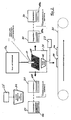
- a first method step delivered test substrates 100 (silicon wafers) are removed from a delivery package and placed in a first storage container as a stack. Individual test substrates 100 are automatically picked up from the storage container by means of a handling device 10 (cf., FIG. 2), for example removed individually from the test substrate stack by means of a suction gripper, so that an automatic pick-up 1 of the substrate 100 to be tested takes place. After automatic picking 1 of the substrate 100 to be tested, the substrate 100 to be tested is checked for a first quality feature in a first test operation 2. The first quality feature is z. B is the hairline freedom test based on a sound measurement of a characteristic "sound image" of the test substrate 100, which will be further explained below.
- test substrate 100 is fed by means of the handling device 10 to a second test operation 3 and / or sorting operation. If the test of the first test operation 2 is negative, the test substrate 100 is fed to a first tray 4 in which scrap is collected based on the first test criterion. Particularly preferably, the degree of filling of the tray 4 is monitored and the tray 4 is replaced by an empty tray 4 when fully filled.
- a color test of the test substrate 100 is performed, which is done by means of industrial image processing.
- a data memory different color comparison and color tolerance values are stored here.
- the surface color of the substrate 100 to be tested is compared with the stored color tolerances and / or color values. If the test gives the surface color, the tested substrate 100 corresponds to the color requirement, the test substrate 100 is fed to a collection device corresponding to the color and / or optionally to another test operation 4.
- the test substrates 100 are sorted according to color value recognized by color values stored in shelves, the test substrates thus undergo a color sorting. If necessary, the test substrates 100 are supplied to a further test operation 4 or forwarded to a subsequent production process for solar cells. If the examination of the test operation 3 is negative, the test substrate 100 is fed to a further tray 5 (reject tray), which in turn may be monitored for filling.
- Particularly preferably 3 further checks of optically detectable features can be carried out in the second test operation, wherein z. B. the peripheral contour and / or the surface image z. B. with regard to the tracks by means of industrial image recording and processing methods recorded, tested and evaluated.
- test criteria of the substrate 100 to be tested can be processed. For example, this can be the weight, or comparable test criteria.
- reject substrates are transferred to a corresponding reject stack 6 and deposited.
- an automatic transfer of the found to be in order substrate 100 to a subsequent process eg. B. the production process of solar cells.
- This method step is identified by the reference numeral 7. After passing the order for okay The automated inspection and handling process according to the invention has been completed.
- sorting operations are carried out in terms of time after the test operation (s).
- the test substrate 100 is preferably produced by means of a handling device 10, e.g. B. a suction pad 10 (see Figure 2) moves from one test station to the next.
- the handling device 10 is z. B. connected to a track 10a.
- the trajectory 10a is z.
- a temporary separation of the test substrate 100 from the handler 10 and a deposition of the test substrate 100 in a test station may occur during a particular test operation.
- the test substrate 100 is moved into a test chamber (not shown) in which a sound sensor 11 (see Fig. 2) is arranged.
- the test substrate 100 here: the silicon wafer
- the test substrate 100 is set in oscillation, so that a sound emission from the test substrate 100 to the sound sensor 11 takes place.
- the vibration excitation can be done in various ways.
- the test substrate 100 may be provided with an excitation body, e.g. a vibration exciter, are brought into contact, so that a structure-borne noise from the excitation body or vibrator to the test substrate 100 transmits and thus puts this into vibration.
- an excitation body e.g. a vibration exciter
- the vibration exciter is in communication with a frequency generator, so that the vibration exciter vibration with defined temporal and amplitude moderate Course on the test substrate 100 in direct contact with this transmits.
- the test substrate 100 is set in vibration and emits a sound emission, which is picked up by the sound sensor 11, which acts as a measuring sensor, and fed to a signal processing device, eg, a measuring and evaluation unit 23.
- a reference signal template is stored, which is characteristic of a defect-free, ie, hairline-free substrate.
- the sound emitted by the test substrate 100 being tested is compared with the reference template. When exceeding critical deviation limits of the recorded sound image of the substrate to be tested in comparison to the reference template, the substrate to be tested is classified as defective.
- the handling device 10 as a gripping device 10, z. B. formed as a suction pads with one or more suction cups, which hold the test substrate 100 by means of negative pressure.
- a single suction gripper which holds the test substrate 100 approximately in the middle, has proven particularly useful.
- an arrangement of several suction pads is conceivable.
- the negative pressure by means of the test substrate 100 is held by the suction pad 10, for a certain time, starting from a nominal negative something lower, ie to increase the absolute pressure somewhat, so that the test substrate 100 solves something from the suction pad, but can not completely separate from the suction pad 10.
- the suction pad is preferred abruptly, again with a lower pressure, z. B. the nominal negative pressure, so that a jerky suction of the test substrate 100 to a stop, z. B. the suction cup bottom occurs.
- the stopper By hitting the stopper, the test substrate 100 undergoes vibration excitation, whereby sound is emitted in the direction of the sound sensor 11.
- this sound has a characteristic frequency profile and / or a characteristic amplitude-time profile. At least one of these courses is picked up by the sound sensor 11 and fed to an evaluation device (not shown), in which the recorded "sound image” is compared with a characteristic "sound image” of a test substrate 100 which has been found to be in good condition.
- the storage devices 4, 5, 6 shown separately in FIG. 1 are combined into a single storage device for broke test substrates.
- a time-decaying vibration of the test substrate 100 is particularly preferably detected by means of the sound sensor 11.
- the device has a traversing unit 10a, on which a gripping means, for. B. the handling device 10, which is designed as a suction pad, is arranged.
- the traversing unit 10a and the handling device 10 form a so-called handling device.
- the moving unit 10a removes a test substrate 100 from the storage container 20 by means of the suction gripper 10 and feeds it to a test chamber 21.
- the direct vibration excitation of the test substrate 100 for example, as described above, by the suction pad 10 itself.
- the acoustic sensor 11 is arranged in the test chamber 21, the acoustic sensor 11 is arranged.
- the acoustic sensor 11 receives the signal emitted from the test substrate 100 Sound, which preferably lies in the audible range, and supplies a corresponding measurement signal to a measurement and evaluation unit 23.
- a measurement and evaluation unit 23 an evaluation of the measurement signal takes place in which it is compared with a reference signal of a reference test substrate 100.
- a device has a camera 24 by means of which a check of the test substrate 100 for optical quality features, for. B. on accuracy of the surface image, accuracy of the trimming contour and / or affiliation to a particular color value.
- the camera 24 is connected to an image processing device 25, in which a camera signal is compared with one or more reference optical signals of a reference test substrate.
- the image processing device 25 is integrated in the camera 24.
- the camera 24 is arranged, for example, above a storage container 20 in which the test substrates 100 are arranged in a stack. This makes it possible, in each case, to subject the uppermost test substrate of a storage container already before receiving the test substrate by the handling device 10 to a test for optical quality features.
- the storage containers 20 preferably have means for monitoring supply and signaling means for displaying the filling level of the storage container 20. Furthermore, the device has at least one storage container 30 for receiving reject test substrates 100a.
- a plurality of storage containers 30 are provided, so that a sorting of the reject test substrates 100a can be carried out by error type. For example, in a first storage container all reject test substrates 100a are arranged, in which the sound check for hairline cracks has been negative. In a second storage container For example, all those reject test substrates 100a may be stored which have contour errors, e.g. B. Outbreaks or errors in the surface image or the like. Thus, it is easier to detect the frequency of occurrence of a particular type of error and, if necessary, to send the reject test substrates 100a back to the supplier in order of errors.
- contour errors e.g. B. Outbreaks or errors in the surface image or the like.
- the device advantageously has interfaces to a quality management system (not shown) in which the test result of each test substrate can be stored for the purpose of documentation.
- the device according to the invention expediently has at least one conveying means 31, by means of the test substrates 100, which have fulfilled all test criteria of further processing, for. B. manufacturing process of a solar cell can be supplied.
- the storage container 30 preferably also have a fill level monitoring and corresponding signal means for displaying the fill level storage container.
- the device according to the invention has means for vibrational excitation of the test substrate 100 in the test chamber 21.
- the means for vibrational excitation z. Example, an excitation body (not shown), which can be brought to the vibration excitation of the test substrate 100 in direct contact with the test substrate 100, so that z. B. structure-borne noise of the excitation body can be transferred to the test substrate 100.
- the means for vibratory excitation of the test substrate 100 may be, for example, a clapper or a percussion hammer or the like, by means of which a direct mechanical vibration excitation of the test substrate 100 can take place.
- the handling device 10 is designed as a vacuum gripper (suction gripper), which with at least one suction cup, the test substrate 100 can grab.
- a control device for controlling the negative pressure of the vacuum gripper is present, by means of which in particular short-term vacuum fluctuations on the suction pads are exercisable, so that by means of the suction pad itself a vibration excitation of the test substrate 100 can take place.
- the vacuum gripper 10 performs functional bundling both with regard to the test substrate transport (material transport) and with regard to the vibration excitation of the test substrate 100.
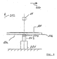
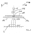
- FIGS. 3 to 6 show a second embodiment of a device according to the invention for carrying out the method. Elements of the same function in comparison to the embodiment according to FIG. 2 are identified by the same reference symbols.
- the device according to the invention has a conveyor 10a in the form of a parallel belt conveyor, on which the test substrates 100 can be transported along a conveying direction 200.
- a traversing unit 201 In a front view between a pair of conveyor belts 10b and below the test substrates 100 there is a traversing unit 201, which can be moved in one direction 202, in particular vertically to the conveying direction 200.
- the movement unit 201 carries a vibration exciter 203, which in particular can be coupled to the test substrate 100 via a suction cup 204, which acts as a vibration coupling element.
- the sound sensor 11 Spaced above the test substrate 100, the sound sensor 11 is arranged.
- a test substrate 100 is disposed above the vibrator 203, by means of the track 201, the vibrator 203 is raised together with the suction cup 204 by a height h, so that the suction cup 204 comes into contact with the underside of the test substrate 100 and this lifts a piece of the conveyor 10a.
- the test substrate 100 can vibrate freely by the conveyor belt pair 10b.
- a vibration signal 205 defined with respect to the frequency and / or amplitude characteristic is transmitted to the test substrate 100 by means of the vibration generator 203 via the suction cup 204.
- the test substrate 100 is thereby excited to oscillate and emits sound waves 206, which are received by the acoustic sensor 11.
- the oscillator 203 and the suction cup 204 are moved down again by the height h so that the test substrate 100 again rests on the conveyor 10a and is transported further in the conveying direction 200 ,
- This embodiment according to FIGS. 3 to 6 also realizes the principle according to the invention, a defined oscillation pattern, i. To enter a defined excitation vibration directly into the test substrate 100 and to record a sound emission of the test substrate 100 by means of an acoustic sensor 11.
- the coupling of the test substrate 100 with the oscillator 203 may take place via a suction cup 204 also via other coupling elements, eg a tripod or other means suitable for supporting test substrates 100. It is essential that the mechanical oscillation provided by the oscillator 203 is transmitted directly to the test substrate 100 without the interposition of an indirect medium, such as air, for example.
- the direct initiation of vibration of the excitation vibration into the test substrate 100 may cause environmental influences, e.g. different ambient air pressure and humidity conditions as well as, for example, the influence of noise sources in the environment are switched off. It has been particularly preferred that the loading of the test substrate 100 with a so-called frequency sweep, i. a timed waveform within the limits of e.g. 5 kHz to 25 kHz, in particular 7 kHz to 20 kHz, proven. It is particularly advantageous to choose a frequency and amplitude curve that is chosen differently from an ideal sinusoidal curve. In particular, for example, trapezoidal or trapezoidal, rectangular or rectangular-like, sawtooth or sawtooth-like or frequency characteristics combined therefrom can be used.
- the evaluation of the sound 206 recorded by the acoustic sensor 11 is then carried out by means of a so-called Fourier analysis. It has been found to be particularly advantageous that with the use of a frequency sweep followed by Fourier analysis for the sound of the acoustic sensor 11 in an effective manner ambient noise are hidden, so that they have no effect on the measurement result.
- the time sequence of the individual test operations 2, 3, 4 shown in FIG. 1 is not to be understood as limiting.
- the individual test operations can also be carried out in a chronologically changed sequence.
- that test operation is advantageously provided, in which a sorting of the test substrates z. B. takes place according to surface colors. This ensures that the sort operation Now test substrates are fed, which have passed through all previous error checking operations positive.
- test substrates silicon wafers
- test result is improved in terms of its constancy and repeatability.
- the method according to the invention and the device according to the invention offer a possibility of testing the test substrates non-destructively and gently for a plurality of test criteria, so that damage and / or destruction of an intact test substrate during the test procedure is precluded.
- the method and the device are suitable to be incorporated into an already existing production line, so that a so-called in-line capability is ensured.
- the invention can be installed both in new production facilities or integrated in addition to existing production facilities.
Landscapes
- Physics & Mathematics (AREA)
- Immunology (AREA)
- General Physics & Mathematics (AREA)
- Chemical & Material Sciences (AREA)
- Analytical Chemistry (AREA)
- Pathology (AREA)
- General Health & Medical Sciences (AREA)
- Life Sciences & Earth Sciences (AREA)
- Health & Medical Sciences (AREA)
- Biochemistry (AREA)
- Acoustics & Sound (AREA)
- Engineering & Computer Science (AREA)
- Signal Processing (AREA)
- Mathematical Physics (AREA)
- Spectroscopy & Molecular Physics (AREA)
- Testing Or Measuring Of Semiconductors Or The Like (AREA)
- Manufacturing Of Magnetic Record Carriers (AREA)
Abstract
Description
Die Erfindung betrifft ein Verfahren zum Handhaben und Prüfen von Siliziumscheiben für die Solarzellenherstellung nach dem Oberbegriff des Anspruchs 1 sowie eine Vorrichtung zum Durchführen des Verfahrens nach dem Oberbegriff des Anspruchs 16.The invention relates to a method for handling and testing silicon wafers for solar cell production according to the preamble of
Hersteller von Solarzellen beziehen üblicherweise Siliziumscheiben (sogenannte wafer) von Halbleiter- bzw. Halbleiterchipherstellern in unterschiedlichen Qualitäten. Geliefert werden z. B. Siliziumscheiben in unterschiedlicher Qualität in unregelmäßiger Aufeinanderfolge. Üblicherweise werden derartige Siliziumscheiben paketweise zu beispielsweise 50 oder 100 Stück beim Hersteller der Solarzellen angeliefert. In einem Paket können Siliziumscheiben unterschiedlicher Qualitäten vorhanden sein. Die Siliziumscheiben können beispielsweise Haarrisse aufweisen, fehlerhafte Konturen besitzen oder Fehler im Aufdruck und Farbunterschiede aufweisen. Weiterhin können die Siliziumscheiben Transportbeschädigungen erfahren haben. Bislang wird beim Hersteller der Solarzellen eine manuelle Eingangsüberprüfung der angelieferten Siliziumscheiben durchgeführt, wobei eine manuelle Entnahme einzelner Siliziumscheiben aus den Paketen erfolgt. Eine Prüfperson überprüft, ob Ausbrechungen an der Kontur vorhanden sind und führt eine Farbeinordnung durch. Zur Feststellung, ob die angelieferten Siliziumscheiben unsichtbare Haarrisse aufweisen, versetzt die Prüfperson die zu prüfende Siliziumscheibe beispielsweise durch Schütteln in eine Schwingung. Dies verursacht eine Schallabgabe durch die in Schwingung versetzte Siliziumscheibe. Die Prüfperson erkennt anhand des abgegebenen Tons, ob es sich um eine haarrissfreie oder eine fehlerhafte Siliziumscheibe handelt und entscheidet dann, ob es sich um Ausschuss oder um eine verwertbare Siliziumscheibe handelt. Die weiter verwertbaren Siliziumscheiben werden üblicherweise wiederum einer Verpackung abgelegt und z. B. nach Farben sortiert dem weiteren Herstellprozess für die Solarzellen zugeführt. Bei dieser derzeit gängigen Eingangsprüfung ist von Nachteil, dass hierfür ein hoher manueller Aufwand erforderlich ist und zudem geschultes Prüfpersonal erforderlich ist, welches zuverlässig anhand des abgestrahlten Schalls feststellen kann, ob eine fehlerhafte Siliziumscheibe vorliegt oder nicht. Außerdem erfolgt z. B. die Farbeinordnung durch die Prüfperson subjektiv, so dass eine zuverlässige objektive Farbsortierung nicht immer gewährleistet ist.Manufacturers of solar cells usually obtain silicon wafers (semiconductor wafers) from semiconductor or semiconductor chip manufacturers in different qualities. Are delivered z. As silicon wafers in different quality in irregular sequence. Usually, such silicon wafers are delivered in packets to, for example, 50 or 100 pieces from the manufacturer of the solar cells. Silicon wafers of different qualities can be present in one package. The silicon wafers may, for example, have hairline cracks, have faulty contours or have errors in the imprint and color differences. Furthermore, the silicon wafers may have suffered transport damage. So far, the manufacturer of the solar cells, a manual input verification of the supplied silicon wafers is performed, with a manual removal of individual silicon wafers from the packages takes place. A test person checks whether there are breakouts on the contour and performs a color classification. To determine if the delivered Silicon discs have invisible hairline cracks, the test person puts the silicon wafer to be tested, for example by shaking in a vibration. This causes a sound emission by the vibrated silicon wafer. On the basis of the sound emitted, the test person recognizes whether it is a hair-crack-free or a defective silicon wafer and then decides whether it is waste or a recyclable silicon wafer. The recyclable silicon wafers are usually stored again a package and z. B. sorted by color supplied to the further manufacturing process for the solar cells. With this currently common entrance examination is a disadvantage that this high manual effort is required and also trained test personnel is required, which can reliably determine the basis of the radiated sound, whether a defective silicon wafer is present or not. In addition, z. B. the color classification by the subject subjectively, so that a reliable objective color sorting is not always guaranteed.
Aus der
Aufgabe der Erfindung ist es, ein automatisiertes Handhabungs- und Prüfverfahren für Werkstücke, insbesondere flachplattenartige Werkstücke, wie z. B. Siliziumscheiben anzugeben, mit dem verschiedene Prüfkriterien einfach und automatisch abgearbeitet werden können. Weiterhin soll eine hohe Prüfsicherheit und eine zuverlässige Sortierung erfolgen. Weiterhin ist es auch Aufgabe der Erfindung, ein Verfahren und eine Vorrichtung anzugeben, welche unterschiedliche Prüfergebnisse durch subjektive Wahrnehmung einer Prüfperson vermeiden. Außerdem soll die Erfindung eine kostengünstige und zuverlässige Eingangsprüfung ermöglichen.The object of the invention is to provide an automated handling and testing method for workpieces, especially flat plate-like workpieces such. As silicon wafers specify, with the various test criteria can be processed easily and automatically. Furthermore, a high inspection reliability and a reliable sorting should be done. Furthermore, it is also an object of the invention to provide a method and a device which avoid different test results by subjective perception of a test person. In addition, the invention should allow a cost-effective and reliable entrance examination.
Diese Aufgaben werden mit einem Verfahren zum Handhaben und Prüfen von Werkstücken mit den Merkmalen des Anspruchs 1 und mit einer Vorrichtung zum Durchführen des Verfahrens mit den Merkmalen des Anspruchs 16 gelöst. Vorteilhafte Ausführungsformen sind den jeweils von den unabhängigen Ansprüchen abhängigen Ansprüchen angegeben.These objects are achieved with a method for handling and inspecting workpieces with the features of
Im Folgenden wird die Erfindung anhand der Zeichnung beispielhaft näher erläutert es zeigen:
- Figur 1:
- schematisch einen Prüfablauf einer Ausführungsform eines erfindungsgemäßen Verfahrens;
- Figur 2:
- schematisch eine erste Ausführungsform einer erfindungsgemäßen Vorrichtung zum Durchführen des Verfahrens;
- Figur 3:
- schematisch eine Vorderansicht auf eine zweite Ausführungsform einer erfindungsgemäßen Vorrichtung zum Durchführen des Verfahrens in einer Ausgangsstellung;
- Figur 4:
- schematisch die zweite Ausführungsform der erfindungsgemäßen Vorrichtung gemäß
Figur 3 in einer Seitenansicht; - Figur 5:
- schematisch die zweite Ausführungsform der erfindungsgemäßen Vorrichtung gemäß
Figur 3 in einer Prüfstellung; und - Figur 6:
- schematisch die zweite Ausführungsform der erfindungsgemäßen Vorrichtung gemäß
Figur 4 in Prüfstellung.
- FIG. 1:
- schematically a test procedure of an embodiment of a method according to the invention;
- FIG. 2:
- schematically a first embodiment of a device according to the invention for carrying out the method;
- FIG. 3:
- schematically a front view of a second embodiment of a device according to the invention for performing the method in a starting position;
- FIG. 4:
- schematically the second embodiment of the device according to the invention according to Figure 3 in a side view;
- FIG. 5:
- schematically the second embodiment of the device according to the invention according to Figure 3 in a test position; and
- FIG. 6:
- schematically the second embodiment of the device according to the invention according to Figure 4 in test position.
Die nachfolgende Beschreibung einer möglichen Ausführungsform des erfindungsgemäßen Verfahrens wird anhand einer Eingangsprüfung von dünnwandigen Siliziumplatten zur Herstellung von Solarzellen beschrieben. Das erfindungsgemäße Verfahren ist aber nicht auf diesen Anwendungsfall beschränkt und kann insbesondere auf flachplattenförmige Bauteile aus anderen Materialien oder auf Prüflinge mit anderen Geometrien mit Vorteil angewandt werden.The following description of a possible embodiment of the method according to the invention will be described with reference to an input test of thin-walled silicon plates for the production of solar cells. However, the method according to the invention is not limited to this application and can be applied in particular to flat plate-shaped components made of other materials or to specimens with other geometries with advantage.
Die in der nachfolgend beschriebenen Verfahrensabfolge zu prüfenden Prüfsubstrate 100, z. B. die Siliziumscheiben, besitzen eine in etwa quadratische Umfangskontur mit einer Kantenlänge von z. B. 200 mm. Die Siliziumscheiben sind mono- oder polykristalline Platten, welche sich in der Farbe unterscheiden können. Beispielsweise kommt es vor, dass die Platten ins rötliche, grünliche oder bläuliche tendieren. Bei der Solarzellenherstellung ist es jedoch wünschenswert, nur gleichfarbige Siliziumplatten in einer Solarzelle zu integrieren, da dies den optischen Eindruck der Solarzelle wesentlich verbessert. Somit ist eine Sortierung nach Farben erforderlich. Außerdem können die Siliziumscheiben ein bestimmtes Oberflächenbild, z. B. bestehend aus Leiterbahnen oder verschiedenen Ätzungen oder Aufdrucken besitzen. Die Prüfung der Fehlerfreiheit des Oberflächenbilds muss zuverlässig erfolgen, um keine fehlerhaften Siliziumscheiben in den nachfolgenden Herstellprozess gelangen zu lassen. Außerdem kann es vorkommen, dass die Siliziumscheiben, insbesondere Siliziumscheiben minderer Qualität, Ausbrüche oder Konturfehler aufweisen. Ein derartiges Auftreten von Ausbrüchen oder Konturfehlern muss dazu führen, dass die entsprechende Siliziumscheibe zuverlässig als Ausschuss erkannt und aussortiert wird. Ein weiteres Prüfkriterium stellt die Prüfung auf Haarrisse dar, welche nicht ohne weiteres optisch erkennbar sind.The
Im folgenden wird verallgemeinernd für die Siliziumscheibe der Begriff "Prüfsubstrat 100"(vgl. Figur 2) verwendet. Selbstverständlich sind je nach zu prüfendem Prüfsubstrat 100 weitere Prüfkriterien und/oder Sortierkriterien denkbar, welche mit dem erfindungsgemäßen Verfahren vorteilhaft abgearbeitet werden können.In the following, the term "
Die Prüfung auf Haarrisse gemäß der Erfindung basiert auf einer Schallmessung eines von einem in Schwingung versetzten Prüfsubstrat 100 abgesandten Schalls. Der abgesandte Schall weist in Abhängigkeit der Geometrie des Prüfsubstrats 100 und der Materialeigenschaften des Prüfsubstrats 100 charakteristische Eigenschaften z. B. hinsichtlich seines zeitlichen Amplitudenverlaufs und/oder seiner Frequenz auf, welche gemessen und in einer Auswerteeinheit mit einem Referenzsignal/Referenzschablone verglichen werden. Abweichungen von dem charakteristischen Prüfsubstratschall (Referenzsignal/Referenzschablone), können als Indikator für einen Fehler, z. B. einen Haarriss herangezogen werden.The hairline crack test according to the invention is based on a sound measurement of a sound sent by a vibrating
Basierend auf den oben genannten Definitionen wird nunmehr das Verfahren anhand von Figur 1 beschrieben.Based on the above definitions, the method will now be described with reference to FIG.
In einem ersten Verfahrensschritt werden angelieferte Prüfsubstrate 100 (Siliziumscheiben) aus einer Anlieferungsverpackung entnommen und in einen ersten Vorratsbehälter als Stapel gegeben. Aus dem Vorratsbehälter werden mittels einer Handhabungseinrichtung 10 (vgl. Figur 2) einzelne Prüfsubstrate 100 automatisch aufgenommen, beispielsweise mittels eines Sauggreifers einzeln vom Prüfsubstratstapel entnommen, so dass eine automatische Aufnahme 1 des zu prüfenden Substrats 100 erfolgt. Nach der automatischen Aufnahme 1 des zu prüfenden Substrats 100 wird das zu prüfende Substrat 100 in einer ersten Prüfoperation 2 auf ein erstes Qualitätsmerkmal überprüft. Das erste Qualitätsmerkmal ist z. B die Prüfung auf Haarrissfreiheit basierend auf einer Schallmessung eines charakteristischen "Schallbilds" des Prüfsubstrats 100, welche weiter unten näher erläutert wird.In a first method step, delivered test substrates 100 (silicon wafers) are removed from a delivery package and placed in a first storage container as a stack.
Sofern die Prüfung der ersten Prüfoperation 2 positiv verläuft, wird das Prüfsubstrat 100 mittels der Handhabungseinrichtung 10 einer zweiten Prüfoperation 3 und/oder Sortieroperation zugeführt. Wenn die Prüfung der ersten Prüfoperation 2 negativ verläuft, wird das Prüfsubstrat 100 einer ersten Ablage 4 zugeführt, in der Ausschuss aufgrund des ersten Prüfkriteriums gesammelt wird. Besonders bevorzugt wird der Füllgrad der Ablage 4 überwacht und die Ablage 4 bei vollständiger Befüllung durch eine leere Ablage 4 ersetzt.If the test of the
In der zweiten Prüfoperation 3 wird beispielsweise eine Farbprüfung des Prüfsubstrats 100 durchgeführt, welche mittels industrieller Bildverarbeitung erfolgt. In einem Datenspeicher sind hierbei verschiedene Farbvergleichs- und Farbtoleranzwerte hinterlegt. Die Oberflächenfarbe des zu prüfenden Substrats 100 wird mit den hinterlegten Farbtoleranzen und/oder Farbwerten verglichen. Sofern die Prüfung der Oberflächenfarbe ergibt, dass das geprüfte Substrat 100 der Farbanforderung entspricht, wird das Prüfsubstrat 100 einer der Farbe entsprechenden Sammeleinrichtung und/oder ggf. einer weiteren Prüfoperation 4 zugeleitet. Alternativ werden die Prüfsubstrate 100 je nach erkanntem Farbwert nach Farbwerten sortiert in Ablagen abgelegt, wobei die Prüfsubstrate somit eine Farbsortierung erfahren. Die Prüfsubstrate 100 werden ggf. einer weiteren Prüfoperation 4 zugeführt oder an einen nachfolgenden Herstellprozess für Solarzellen weitergegeben. Wenn die Prüfung der Prüfoperation 3 negativ verläuft, wird das Prüfsubstrat 100 einer weiteren Ablage 5 (Ausschussablage) zugeführt, welche ggf. wiederum hinsichtlich der Füllung überwacht wird.In the
Besonders bevorzugt können in der zweiten Prüfoperation 3 weitere Überprüfungen von optisch erfassbaren Merkmalen erfolgen, wobei z. B. die Umfangskontur und/oder das Oberflächenbild z. B. hinsichtlich der Leiterbahnen mittels industriellen Bildaufnahme- und Verarbeitungsverfahren erfasst, geprüft und bewertet werden.Particularly preferably 3 further checks of optically detectable features can be carried out in the second test operation, wherein z. B. the peripheral contour and / or the surface image z. B. with regard to the tracks by means of industrial image recording and processing methods recorded, tested and evaluated.
In der dritten oder in folgenden Prüfoperationen 4 können weitere Prüfkriterien des zu prüfenden Substrats 100 abgearbeitet werden. In Frage kommen hierfür zum Beispiel das Gewicht, oder vergleichbare Prüfkriterien. In der dritten oder in fortfolgenden Prüfoperationen 4 werden jeweils bei negativem Ausgang der Prüfung und negativer Bewertung des entsprechenden Prüfkriteriums Ausschusssubstrate in eine entsprechende Ausschussablage 6 übergeführt und abgelegt. Am Ende des gesamten Prüfzyklussees, d. h. am Ende der dritten oder n-ten Prüfoperation, erfolgt bei positiver Gesamtprüfung des Substrats 100 eine automatische Übergabe des für in Ordnung befundenen Substrats 100 an einen Nachfolgeprozess, z. B. den Herstellprozess von Solarzellen. Dieser Verfahrensschritt ist mit dem Bezugszeichen 7 gekennzeichnet. Nach der Übergabe der für in Ordnung befundenen Prüfsubstrate 100 an den Nachfolgeprozess ist das automatisierte Handhabungs- und Prüfverfahren gemäß der Erfindung beendet.In the third or following
Bevorzugt werden Sortieroperationen zeitlich nach der oder den Prüfoperationen durchgeführt.Preferably, sorting operations are carried out in terms of time after the test operation (s).
Während des gesamten Prüfverfahrens wird das Prüfsubstrat 100 vorzugsweise mittels einer Handhabungseinrichtung 10, z. B. einem Sauggreifer 10 (vgl. Figur 2) von einer Prüfstation zur nächsten bewegt. Die Handhabungseinrichtung 10 ist z. B. mit einer Verfahreinheit 10a verbunden. Die Verfahreinheit 10a ist z. B. ein Industrieroboter oder ein Linearförderer oder dergleichen. Sofern es erforderlich ist, kann während einer bestimmten Prüfoperation eine vorübergehende Trennung des Prüfsubstrats 100 von der Handhabungseinrichtung 10 und eine Ablage des Prüfsubstrats 100 in einer Prüfstation erfolgen. Bei der Prüfoperation 2, nämlich der Haarrissprüfung 100 wird das Prüfsubstrat 100 in eine Prüfkammer (nicht gezeigt) bewegt, in der ein Schallsensor 11 (vgl. Fig. 2) angeordnet ist. In der Prüfkammer wird das Prüfsubstrat 100 (hier: die Siliziumscheibe) in Schwingung versetzt, so dass vom Prüfsubstrat 100 eine Schallemission hin zum Schallsensor 11 erfolgt.During the entire test procedure, the
Die Schwingungserregung kann auf verschiedene Art und Weise erfolgen. Beispielsweise kann das Prüfsubstrat 100 mit einem Anregungskörper, z.B. einem Schwingerreger, in Kontakt gebracht werden, so dass sich ein Körperschall vom Anregungskörper oder Schwingerreger auf das Prüfsubstrat 100 überträgt und somit dieses in Schwingung versetzt.The vibration excitation can be done in various ways. For example, the
Hierbei steht bevorzugt der Schwingerreger mit einem Frequenzgenerator in Verbindung, so dass der Schwingerreger eine Schwingung mit definiertem zeitlichen und amplitudenmäßigen Verlauf auf das Prüfsubstrat 100 in direktem Kontakt mit diesem überträgt. Das Prüfsubstrat 100 wird hierdurch in Schwingung versetzt und gibt eine Schallemission ab, die von dem Schallsensor 11, der als Messwertaufnehmer wirkt, aufgenommen und einer Signalverarbeitungseinrichtung, z.B. einer Mess- und Auswerteeinheit 23 zugeleitet wird. In der Mess- und Auswerteeinrichtung 23 ist eine Referenzsignalschablone abgelegt, die für ein fehlerfreies, d.h. haarrissfreies Substrat charakteristisch ist. Der vom in Prüfung befindlichen Prüfsubstrat 100 abgesandte Schall wird mit der Referenzschablone verglichen. Beim Überschreiten von kritischen Abweichungsgrenzen des aufgenommenen Schallbildes des zu prüfenden Substrates im Vergleich zur Referenzschablone, wird das zu prüfende Substrat als fehlerhaft eingestuft.In this case, preferably, the vibration exciter is in communication with a frequency generator, so that the vibration exciter vibration with defined temporal and amplitude moderate Course on the
Als besonders bevorzugt hat sich auch erwiesen, die Schwingungserregung des Prüfsubstrats 100 mittels der Handhabungseinrichtung 10 selbst zu bewerkstelligen. Beispielsweise ist die Handhabungseinrichtung 10 als Greifeinrichtung 10, z. B. als Sauggreifer mit einem oder mehreren Saugnäpfen ausgebildet, welche das Prüfsubstrat 100 mittels Unterdruck halten. Besonders bewährt hat sich hierbei ein einzelner Sauggreifer, welcher das Prüfsubstrat 100 in etwa mittig hält. Je nach Größe des Prüfsubstrats 100 ist jedoch auch eine Anordnung mehrer Sauggreifer denkbar.It has also proven to be particularly advantageous to accomplish the oscillation excitation of the
Als besonders bevorzugt zur Schwingungserregung des Prüfsubstrates 100 hat sich erwiesen, in der Prüfkammer den Unterdruck, mittels dem das Prüfsubstrat 100 vom Sauggreifer 10 gehalten wird, für eine bestimmte Zeit ausgehend von einem Nennunterdruck etwas abzusenken, d. h. den absoluten Druck etwas zu steigern, so dass sich das Prüfsubstrat 100 etwas vom Sauggreifer löst, sich jedoch nicht vollständig vom Sauggreifer 10 trennen kann. Anschließend wird der Sauggreifer, bevorzugt schlagartig, wieder mit einem niedrigeren Druck, z. B. dem Nennunterdruck, beaufschlagt, so dass ein ruckartiges Ansaugen des Prüfsubstrats 100 bis zu einem Anschlag, z. B. dem Saugnapfboden, erfolgt. Durch das Auftreffen auf den Anschlag erfährt das Prüfsubstrat 100 eine Schwingungsanregung, wobei Schall in Richtung des Schallsensors 11 abgestrahlt wird. Dieser Schall weist je nach Prüfsubstrattyp einen charakteristischen Frequenzverlauf und/oder einen charakteristischen Amplituden-Zeitverlauf auf. Zumindest einer dieser Verläufe wird vom Schallsensor 11 aufgenommen und einer Auswerteeinrichtung (nicht gezeigt) zugeleitet, in der das aufgenommene "Schallbild" mit einem charakteristischen "Schallbild" eines qualitativ für gut befundenen Prüfsubstrats 100 verglichen wird.As particularly preferred for the vibration excitation of the
Weiterhin kann die Schwingungsanregung des Prüfsubstrats 100 durch ein z. B. mechanisches Anklopfen oder Anschlagen auf das Prüfsubstrat 100 erfolgen, wobei dies bevorzugt ohne Trennung des Prüfsubstrats 100 von der Handhabungseinrichtung 10 durch geeignete Anregungsmittel, z. B. einem Schlagkörper, erfolgt.Furthermore, the vibration excitation of the
Die im Stand der Technik gemäß der
Dies bewirkt eine hohe Reproduzierbarkeit der Schwingungsanregung des Prüfsubstrats 100 und somit eine erleichterte messtechnische Auswertung des durch das Prüfsubstrat 100 abgestrahlten Schallsignals.This causes a high reproducibility of the vibration excitation of the
Gemäß einer weiteren alternativen Ausführungsform sind die in Figur 1 getrennt dargestellten Ablageeinrichtungen 4, 5, 6 zu einer einzigen Ablageeinrichtung für Ausschuss-Prüfsubstrate zusammengefasst.According to a further alternative embodiment, the
Weiterhin hat sich als besonders vorteilhaft erwiesen, das Prüfsubstrat 100 in einem ersten Schritt in Schwingung zu versetzen und nachdem eine Schwingung ins Substrat 100 eingetragen wurde, die Messauswertung zu beginnen. Dies hat den Vorteil, dass die Schwingungsanregung selbst nicht störend, die Messwerte verfälschend wirkt. Somit wird besonders bevorzugt mittels dem Schallsensor 11 eine zeitlich abklingende Schwingung des Prüfsubstrats 100 erfasst.Furthermore, it has proved to be particularly advantageous to vibrate the
Im folgenden wird anhand der Figur 2 beispielhaft eine Ausführungsform einer erfindungsgemäßen Vorrichtung zum Durchführen des Verfahrens beschrieben. Die Vorrichtung weist eine Verfahreinheit 10a, an welcher ein Greifmittel, z. B. die Handhabungseinrichtung 10, welche als Sauggreifer ausgebildet ist, angeordnet ist. Die Verfahreinheit 10a und die Handhabungseinrichtung 10 bilden eine sogenannte Handlingseinrichtung. Die Verfahreinheit 10a entnimmt mittels dem Sauggreifer 10 aus einem der Vorratsbehälter 20 ein Prüfsubstrat 100 und führt es einer Prüfkammer 21 zu. In der Prüfkammer 21 erfolgt die direkte Schwingungsanregung des Prüfsubstrats 100 beispielsweise, wie oben beschrieben, durch den Sauggreifer 10 selbst.In the following, an embodiment of a device according to the invention for carrying out the method will be described by way of example with reference to FIG. The device has a
In der Prüfkammer 21 ist der Akustiksensor 11 angeordnet. Der Akustiksensor 11 empfängt den vom Prüfsubstrat 100 ausgesandten Schall, welcher bevorzugt im hörbaren Bereich liegt, und führt ein korrespondierendes Messsignal einer Mess- und Auswerteeinheit 23 zu. In der Mess- und Auswerteeinheit 23 erfolgt eine Auswertung des Messsignals, in dem es mit einem Referenzsignal eines Referenz-Prüfsubstrats 100 verglichen wird.In the
Weiterhin weist eine erfindungsgemäße Vorrichtung eine Kamera 24 auf mittels der eine Überprüfung des Prüfsubstrats 100 auf optische Qualitätsmerkmale, z. B. auf Fehlerfreiheit des Oberflächenbilds, auf Fehlerfreiheit der Beschnittkontur und/oder auf Zugehörigkeit zu einem bestimmten Farbwert erfolgt. Die Kamera 24 ist mit einer Bildverarbeitungseinrichtung 25 verbunden, in der ein Kamerasignal mit einem oder mehreren optischen Referenzsignalen eines Referenzprüfsubstrats verglichen werden. Bevorzugt ist die Bildverarbeitungseinrichtung 25 in der Kamera 24 integriert ausgebildet.Furthermore, a device according to the invention has a
Die Kamera 24 ist beispielsweise oberhalb eines Vorratsbehälters 20, in dem die Prüfsubstrate 100 stapelförmig angeordnet sind, angeordnet. Hierdurch ist es möglich, jeweils das oberste Prüfsubstrat eines Vorratsbehälters bereits schon vor der Aufnahme des Prüfsubstrats durch die Handhabungseinrichtung 10 einer Prüfung auf optische Qualitätsmerkmale zu unterziehen.The
Die Vorratsbehälter 20 weisen bevorzugt mittel zur Vorratsüberwachung und Signalisierungsmittel zur Anzeige des Füllstands Vorratsbehälters 20 auf. Weiterhin besitzt die Vorrichtung zumindest einen Ablagebehälter 30 zur Aufnahme von Ausschuss-Prüfsubstraten 100a. Vorteilhafterweise sind mehrere Ablagebehälter 30 vorgesehen, so dass eine Sortierung der Ausschuss-Prüfsubstrate 100a nach Fehlertyp erfolgen kann. Beispielsweise sind in einem ersten Ablagebehälter alle Ausschuss-Prüfsubstrate 100a angeordnet, bei denen die Schallprüfung auf Haarrisse negativ verlaufen ist. In einem zweiten Ablagebehälter können beispielsweise alle diejenigen Ausschuss-Prüfsubstrate 100a abgelegt sein, welche Konturfehler, z. B. Ausbrüche oder Fehler im Oberflächenbild oder dergleichen aufweisen. Somit ist es erleichtert, die Häufigkeit des Auftretens eines bestimmten Fehlertyps zu erkennen und ggf. die Ausschuss-Prüfsubstrate 100a nach Fehlern geordnet zum Lieferanten zurück schicken zu können.The
Weiterhin weist die Vorrichtung vorteilhafterweise Schnittstellen zu einem Qualitätsmanagementsystem (nicht gezeigt) auf, in dem das Prüfergebnis eines jeden Prüfsubstrats zum Zwecke der Dokumentation abgelegt werden kann. Des weiteren besitzt die erfindungsgemäße Vorrichtung zweckmäßigerweise zumindest ein Fördermittel 31, mittels dem Prüfsubstrate 100, welche alle Prüfkriterien erfüllt haben der weiteren Verarbeitung, z. B. Herstellprozess einer Solarzelle zugeführt werden können. Die Ablagebehälter 30 weisen bevorzugt ebenfalls eine Füllstandsüberwachung und entsprechende Signalmittel zur Anzeige des Füllstands Ablagebehälters auf.Furthermore, the device advantageously has interfaces to a quality management system (not shown) in which the test result of each test substrate can be stored for the purpose of documentation. Furthermore, the device according to the invention expediently has at least one conveying
Außerdem besitzt die erfindungsgemäße Vorrichtung Mittel zur Schwingungsanregung des Prüfsubstrats 100 in der Prüfkammer 21. Die Mittel zur Schwingungsanregung können z. B. ein Anregungskörper (nicht gezeigt) sein, welcher zur Schwingungsanregung des Prüfsubstrats 100 in direkten Kontakt mit dem Prüfsubstrat 100 bringbar ist, so dass z. B. Körperschall des Anregungskörpers auf das Prüfsubstrat 100 übertragen werden kann. Weiterhin können die Mittel zum Schwingungsanregen des Prüfsubstrats 100 beispielsweise ein Klöppel oder ein Schlaghammer oder dergleichen sein, mittels dem eine direkte mechanische Schwingungsanregung des Prüfsubstrats 100 erfolgen kann. Gemäß einer besonders bevorzugten Ausführungsform ist die Handhabungseinrichtung 10 als Vakuumgreifer (Sauggreifer) ausgebildet, welcher mit zumindest einem Saugnapf das Prüfsubstrat 100 greifen kann. Bevorzugt ist eine Steuereinrichtung zur Ansteuerung des Unterdrucks des Vakuumgreifers vorhanden, mittels der insbesondere kurzzeitige Unterdruckschwankungen auf den Sauggreifer ausübbar sind, so dass mittels dem Sauggreifer selbst eine Schwingungserregung des Prüfsubstrats 100 erfolgen kann. Bei dieser Ausführungsform ist besonders vorteilhaft, dass der Vakuumgreifer 10 eine Funktionsbündelung sowohl hinsichtlich des Prüfsubstratstransportes (Materialtransport) als auch hinsichtlich der Schwingungserregung des Prüfsubstrats 100 erfüllt.In addition, the device according to the invention has means for vibrational excitation of the
In Figur 3 bis Figur 6 ist eine zweite Ausführungsform einer erfindungsgemäßen Vorrichtung zum Durchführen des Verfahrens dargestellt. Elemente gleicher Funktion im Vergleich zur Ausführungsform gemäß Figur 2 sind mit gleichen Bezugszeichen gekennzeichnet.FIGS. 3 to 6 show a second embodiment of a device according to the invention for carrying out the method. Elements of the same function in comparison to the embodiment according to FIG. 2 are identified by the same reference symbols.
Die erfindungsgemäße Vorrichtung weist eine als Parallelbandförderer ausgebildete Fördereinrichtung 10a auf, auf der die Prüfsubstrate 100 entlang einer Förderrichtung 200 transportierbar sind. In einer Vorderansicht zwischen einem Förderbandpaar 10b und unterhalb der Prüfsubstrate 100 befindet sich eine Verfahreinheit 201, welche in einer Richtung 202, insbesondere vertikal zur Förderrichtung 200 ausfahrbar ist. Die Verfahreinheit 201 trägt einen Schwingerreger 203, welcher insbesondere über einen Saugnapf 204, der als Schwingungskopplungsglied wirkt mit dem Prüfsubstrat 100 koppelbar ist. Beabstandet oberhalb des Prüfsubstrats 100 ist der Schallsensor 11 angeordnet.The device according to the invention has a
Wenn mittels der Fördereinrichtung 10a ein Prüfsubstrat 100 über dem Schwingerreger 203 angeordnet ist, wird mittels der Verfahreinheit 201 der Schwingerreger 203 zusammen mit dem Saugnapf 204 um eine Höhe h angehoben, so dass der Saugnapf 204 unterseitig mit dem Prüfsubstrat 100 in Kontakt gelangt und dieses ein Stück von der Fördereinrichtung 10a abhebt. Hierdurch kann das Prüfsubstrat 100 unbeeinträchtigt durch das Förderbandpaar 10b frei schwingen. In dieser Stellung wird mittels dem Schwingerreger 203 über dem Saugnapf 204 ein hinsichtlich des Frequenz- und/oder Amplitudenverlaufs definiertes Schwingungssignal 205 auf das Prüfsubstrat 100 übertragen. Das Prüfsubstrat 100 wird hierdurch zum Schwingen angeregt und sendet Schallwellen 206 ab, die vom Akustiksensor 11 aufgenommen werden. Nach der Aufnahme der abgesandten Schallwellen 206 durch den Akustiksensor 11 wird mittels der Verfahreinheit 201 der Schwingerreger 203 und der Saugnapf 204 wieder um die Höhe h nach unten gefahren, so dass das Prüfsubstrat 100 wiederum auf der Fördereinrichtung 10a aufliegt und in Förderrichtung 200 weiter transportiert wird.If by means of the
Auch diese Ausführungsform gemäß den Figuren 3 bis 6 verwirklicht das erfindungsgemäße Prinzip, ein definiertes Schwingungsmuster, d.h. eine definierte Erregungsschwingung in das Prüfsubstrat 100 direkt gekoppelt einzutragen und eine Schallemission des Prüfsubstrats 100 mittels eines Akustiksensors 11 aufzunehmen.This embodiment according to FIGS. 3 to 6 also realizes the principle according to the invention, a defined oscillation pattern, i. To enter a defined excitation vibration directly into the
Gemäß weiterer vorteilhafter Ausführungsformen kann die Kopplung des Prüfsubstrats 100 mit dem Schwingerreger 203 anstelle über einen Saugnapf 204 auch über andere Kopplungselemente, z.B. ein Dreibein oder andere zur Auflage von Prüfsubstraten 100 geeignete Mittel erfolgen. Wesentlich ist, dass die durch den Schwingerreger 203 zur Verfügung gestellte mechanische Schwingung ohne Zwischenschaltung eines indirekten Mediums, wie z.B. Luft direkt gekoppelt auf das Prüfsubstrat 100 übertragen wird.According to further advantageous embodiments, the coupling of the
Durch die direkte Schwingungseinleitung der Erregerschwingung in das Prüfsubstrat 100 können Umwelteinflüsse, z.B. unterschiedliche Luftdruck-, Luftfeuchtigkeitsgegebenheiten in der Umgebung wie auch beispielsweise der Einfluss von Geräuschquellen in der Umgebung ausgeschaltet werden. Als besonders bevorzugt hat sich die Beaufschlagung des Prüfsubstrats 100 mit einen sogenannten Frequenzsweep, d.h. einen zeitlich definierten Schwingungsverlauf in den Grenzen von z.B. 5 kHz bis 25 kHz, insbesondere 7 kHz bis 20 kHz, bewährt. Insbesondere vorteilhaft ist es, einen Frequenz- und Amplitudenverlauf zu wählen, der abweichend von einem idealen Sinusverlauf gewählt wird. Insbesondere können beispielsweise trapez- oder trapezähnliche, rechteck- oder rechteckähnliche, sägezahn- oder sägezahnähnliche oder hieraus kombinierte Frequenzverläufe verwendet werden. Die Auswertung des vom Akustiksensor 11 aufgenommenen Schalles 206 erfolgt anschließend mittels einer sogenannten Fourieranalyse. Hierbei hat sich als besonders vorteilhaft herausgestellt, dass bei der Verwendung eines Frequenzsweeps mit anschließender Fourieranalyse auch für die Schallaufnahme des Akustiksensors 11 in wirksamer Art und Weise Umgebungsgeräusche ausgeblendet werden, so dass diese keinen Einfluss auf das Messergebnis haben.The direct initiation of vibration of the excitation vibration into the
Selbstverständlich ist die im Rahmen der Figur 1 dargestellte zeitliche Abfolge der einzelnen Prüfoperationen 2, 3, 4 nicht limitierend zu verstehen. Die einzelnen Prüfoperationen können auch in einer zeitlich geänderten Aufeinanderfolge durchgeführt werden. Als besonders vorteilhaft hat sich jedoch erwiesen, zuerst alle diejenigen Prüfoperationen durchzuführen, welche zwischen einem verwertbaren Prüfsubstrat und einem Ausschuss-Prüfsubstrat unterscheiden. Als letzten Schritt ist vorteilhafterweise diejenige Prüfoperation vorgesehen, bei der eine Sortierung der Prüfsubstrate z. B. nach Oberflächenfarben erfolgt. Hierbei ist sichergestellt, dass der Sortieroperation nunmehr Prüfsubstrate zugeleitet werden, welche alle vorangegangen Fehlerprüfoperationen positiv durchlaufen haben.Of course, the time sequence of the
Besonders vorteilhaft beim erfindungsgemäßen Verfahren und bei der erfindungsgemäßen Vorrichtung zum Durchführen des Verfahrens ist, dass die Eingangsprüfung von z. B. Siliziumscheiben für die Herstellung von Solarzellen vollautomatisch ohne manuelle Eingriffe einer Prüfperson durchführbar ist. Weiterhin ist von besonderem Vorteil, dass die Prüfung der Prüfsubstrate (Siliziumscheiben) objektiv, d. h. nach festgelegten Kriterien auch über lange Zeit hinweg, unabhängig von subjektiven Eindrücken einer Prüfperson erfolgt. Somit ist das Prüfergebnis hinsichtlich seiner Konstanz und Wiederholbarkeit verbessert. Weiterhin ist von besonderem Vorteil, dass das erfindungsgemäße Verfahren und die erfindungsgemäße Vorrichtung eine Möglichkeit bieten, die Prüfsubstrate zerstörungsfrei und schonend auf eine Mehrzahl von Prüfkriterien zu prüfen, so dass eine Beschädigung und/oder Zerstörung eines intakten Prüfsubstrats während dem Prüfvorgang ausgeschlossen ist.Particularly advantageous in the method according to the invention and in the apparatus according to the invention for carrying out the method is that the entrance examination of z. B. silicon wafers for the production of solar cells fully automatically without manual intervention by a test person is feasible. Furthermore, it is of particular advantage that the test of the test substrates (silicon wafers) objectively, d. H. according to defined criteria, even over a long period of time, regardless of the subjective impressions of a test person. Thus, the test result is improved in terms of its constancy and repeatability. Furthermore, it is of particular advantage that the method according to the invention and the device according to the invention offer a possibility of testing the test substrates non-destructively and gently for a plurality of test criteria, so that damage and / or destruction of an intact test substrate during the test procedure is precluded.
Insbesondere ist das Verfahren und die Vorrichtung geeignet in eine bereits bestehende Herstelllinie eingegliedert zu werden, so dass eine sogenannte Inlinefähigkeit gewährleistet ist. Somit kann die Erfindung sowohl in neuen Produktionsanlagen eingebaut werden oder ergänzend zu bereits bestehenden Produktionsanlagen eingebunden werden.In particular, the method and the device are suitable to be incorporated into an already existing production line, so that a so-called in-line capability is ensured. Thus, the invention can be installed both in new production facilities or integrated in addition to existing production facilities.
Claims (37)
Applications Claiming Priority (1)
| Application Number | Priority Date | Filing Date | Title |
|---|---|---|---|
| DE200510028920 DE102005028920A1 (en) | 2005-06-22 | 2005-06-22 | Method for handling and checking workpieces and apparatus for carrying out the method |
Publications (2)
| Publication Number | Publication Date |
|---|---|
| EP1736766A2 true EP1736766A2 (en) | 2006-12-27 |
| EP1736766A3 EP1736766A3 (en) | 2007-12-05 |
Family
ID=36996488
Family Applications (1)
| Application Number | Title | Priority Date | Filing Date |
|---|---|---|---|
| EP06012663A Withdrawn EP1736766A3 (en) | 2005-06-22 | 2006-06-20 | Method for handling and testing work pieces and device for carrying out the method |
Country Status (2)
| Country | Link |
|---|---|
| EP (1) | EP1736766A3 (en) |
| DE (1) | DE102005028920A1 (en) |
Cited By (5)
| Publication number | Priority date | Publication date | Assignee | Title |
|---|---|---|---|---|
| CN104259109A (en) * | 2014-07-28 | 2015-01-07 | 中国电子科技集团公司第四十八研究所 | Stepping silicon wafer quality sorting system |
| CN107315049A (en) * | 2017-07-31 | 2017-11-03 | 苏州东菱智能减振降噪技术有限公司 | A kind of ceramic tile detector and detection method |
| CN109622392A (en) * | 2018-12-28 | 2019-04-16 | 温州市天瑞制药机械有限公司 | A kind of soft capsule video automatic sorting device |
| CN112495824A (en) * | 2020-11-09 | 2021-03-16 | 温州市凌度电子科技有限公司 | Transmission mechanism of solar panel |
| CN113155962A (en) * | 2021-03-22 | 2021-07-23 | 绍兴柯桥亮剑机械有限公司 | Casting burr detection equipment based on ultrasonic waves and system thereof |
Families Citing this family (6)
| Publication number | Priority date | Publication date | Assignee | Title |
|---|---|---|---|---|
| DE102007010516A1 (en) * | 2007-03-05 | 2008-09-18 | Intego Gmbh | Polycrystalline origin identification involves determining product image of product with comparison picture of comparison product in polycrystalline structure with help of image evaluation |
| CN106298568B (en) * | 2016-07-25 | 2019-04-12 | 河海大学常州校区 | A kind of detection method of the grey piece of solar battery sheet |
| CN109894377B (en) * | 2019-04-01 | 2023-05-23 | 山东九思新材料科技有限责任公司 | Belt conveyor and silicon material automatic sorting system |
| CN110238074B (en) * | 2019-06-27 | 2022-12-23 | 南京涵铭置智能科技有限公司 | Button sorting machine based on color identification and sorting method thereof |
| CN110721928B (en) * | 2019-10-21 | 2021-02-05 | 武汉纺织大学 | Color difference sorting method and system for solar cells |
| DE102020122008A1 (en) | 2020-08-24 | 2022-02-24 | Bayerische Motoren Werke Aktiengesellschaft | Test procedure, use and test bench arrangement |
Citations (5)
| Publication number | Priority date | Publication date | Assignee | Title |
|---|---|---|---|---|
| DE3943133A1 (en) * | 1989-12-28 | 1991-07-18 | Zeuna Staerker Kg | METHOD FOR ACOUSTICALLY TESTING MONOLITHS FOR DAMAGE AND DEVICE FOR IMPLEMENTING THE METHOD |
| US6062084A (en) * | 1999-01-29 | 2000-05-16 | Taiwan Semiconductor Manufacturing Co., Ltd. | Apparatus for detecting wafer edge defects and method of using |
| EP1302769A2 (en) * | 2001-10-15 | 2003-04-16 | Intermet Neunkirchen GmbH | Method for checking the quality of cast pieces |
| DE10345577A1 (en) * | 2003-09-29 | 2005-05-12 | Hans Thoma | Sound-based device for checking for hairline cracks in silicon slices used in the manufacture of solar cells comprises a sound source that transmits sound waves towards the slice and a recorder for detecting transmitted sound |
| US20050097961A1 (en) * | 2003-11-10 | 2005-05-12 | Sharp Kabushiki Kaisha | Substrate crack inspecting method, substrate crack inspection apparatus, and solar battery module manufacturing method |
Family Cites Families (2)
| Publication number | Priority date | Publication date | Assignee | Title |
|---|---|---|---|---|
| US6605807B2 (en) * | 2000-06-05 | 2003-08-12 | The Boeing Company | Infrared crack detection apparatus and method |
| JP4349478B2 (en) * | 2001-02-09 | 2009-10-21 | チューナー株式会社 | Automotive electronic devices |
-
2005
- 2005-06-22 DE DE200510028920 patent/DE102005028920A1/en not_active Ceased
-
2006
- 2006-06-20 EP EP06012663A patent/EP1736766A3/en not_active Withdrawn
Patent Citations (5)
| Publication number | Priority date | Publication date | Assignee | Title |
|---|---|---|---|---|
| DE3943133A1 (en) * | 1989-12-28 | 1991-07-18 | Zeuna Staerker Kg | METHOD FOR ACOUSTICALLY TESTING MONOLITHS FOR DAMAGE AND DEVICE FOR IMPLEMENTING THE METHOD |
| US6062084A (en) * | 1999-01-29 | 2000-05-16 | Taiwan Semiconductor Manufacturing Co., Ltd. | Apparatus for detecting wafer edge defects and method of using |
| EP1302769A2 (en) * | 2001-10-15 | 2003-04-16 | Intermet Neunkirchen GmbH | Method for checking the quality of cast pieces |
| DE10345577A1 (en) * | 2003-09-29 | 2005-05-12 | Hans Thoma | Sound-based device for checking for hairline cracks in silicon slices used in the manufacture of solar cells comprises a sound source that transmits sound waves towards the slice and a recorder for detecting transmitted sound |
| US20050097961A1 (en) * | 2003-11-10 | 2005-05-12 | Sharp Kabushiki Kaisha | Substrate crack inspecting method, substrate crack inspection apparatus, and solar battery module manufacturing method |
Cited By (7)
| Publication number | Priority date | Publication date | Assignee | Title |
|---|---|---|---|---|
| CN104259109A (en) * | 2014-07-28 | 2015-01-07 | 中国电子科技集团公司第四十八研究所 | Stepping silicon wafer quality sorting system |
| CN107315049A (en) * | 2017-07-31 | 2017-11-03 | 苏州东菱智能减振降噪技术有限公司 | A kind of ceramic tile detector and detection method |
| CN109622392A (en) * | 2018-12-28 | 2019-04-16 | 温州市天瑞制药机械有限公司 | A kind of soft capsule video automatic sorting device |
| CN109622392B (en) * | 2018-12-28 | 2024-05-03 | 浙江天瑞制药机械有限公司 | Automatic soft capsule video sorting device |
| CN112495824A (en) * | 2020-11-09 | 2021-03-16 | 温州市凌度电子科技有限公司 | Transmission mechanism of solar panel |
| CN112495824B (en) * | 2020-11-09 | 2022-08-09 | 山西晋通送变电有限公司 | Transmission mechanism of solar panel |
| CN113155962A (en) * | 2021-03-22 | 2021-07-23 | 绍兴柯桥亮剑机械有限公司 | Casting burr detection equipment based on ultrasonic waves and system thereof |
Also Published As
| Publication number | Publication date |
|---|---|
| EP1736766A3 (en) | 2007-12-05 |
| DE102005028920A1 (en) | 2006-12-28 |
Similar Documents
| Publication | Publication Date | Title |
|---|---|---|
| EP1736766A2 (en) | Method for handling and testing work pieces and device for carrying out the method | |
| EP1895297B1 (en) | Method for the nondestructive material testing of highly pure polycrystalline silicon | |
| DE69032143T2 (en) | Non-destructive testing of structural elements | |
| US20090056825A1 (en) | Device for the Monitored Filling of Containers with Tablets | |
| AT393198B (en) | WAFFLE DOUGH, BAKED DOUBLE DOUGH OR THE LIKE | |
| DE60014387T2 (en) | METHOD AND DEVICE FOR DETERMINING THE HARDENESS OF A PRODUCT SUCH AS FRUIT | |
| DE102017112307B4 (en) | METHOD AND DEVICE FOR EVALUATION OF AN ULTRASONIC WELD JOINT | |
| US8365598B2 (en) | Device and method for quality testing sheet metal parts | |
| WO2004028939A2 (en) | Gripping device comprising means for detecting double feeding and method for the operation thereof | |
| EP3899486B1 (en) | Device and method for ascertaining mechanical properties of a test body | |
| US20210131933A1 (en) | System for analyzing impact and puncture resistance | |
| DE102012204282A1 (en) | Device for testing pressed workpieces | |
| WO2009130230A1 (en) | Method and device for the destruction-free ultrasound detection of defects on the inside of a semiconductor material | |
| DE102019109263A1 (en) | METHOD FOR NON-DESTRUCTIVE TESTING OF A QUALITY OF AN ULTRASONIC WELDING | |
| CH705370A1 (en) | Method and apparatus for inspection of a semiconductor chip before assembly. | |
| DE1648540A1 (en) | Method and device for testing the tightness of objects | |
| DE3936163A1 (en) | Measuring soundness of hermetically sealed containers - subjecting flexible part to pressure in test chamber and comparing deformation arising from internal pressure | |
| DE3300259C2 (en) | ||
| DE102008008276B4 (en) | Apparatus and method for detecting defects of monocrystalline or polycrystalline silicon wafers | |
| DE102017012007A1 (en) | Apparatus and method for universal acoustic testing of objects | |
| JPH0392758A (en) | Product inspection | |
| JP5013058B2 (en) | Defect detection method and apparatus | |
| EP0036909A2 (en) | Method for non-destructive inspection of components | |
| DE102020211723A1 (en) | METHOD OF PROCESSING A WAFER AND A CHIP MEASURING DEVICE | |
| DE10321389B4 (en) | Method and device for acoustic quality inspection of small parts |
Legal Events
| Date | Code | Title | Description |
|---|---|---|---|
| PUAI | Public reference made under article 153(3) epc to a published international application that has entered the european phase |
Free format text: ORIGINAL CODE: 0009012 |
|
| AK | Designated contracting states |
Kind code of ref document: A2 Designated state(s): AT BE BG CH CY CZ DE DK EE ES FI FR GB GR HU IE IS IT LI LT LU LV MC NL PL PT RO SE SI SK TR |
|
| AX | Request for extension of the european patent |
Extension state: AL BA HR MK YU |
|
| PUAL | Search report despatched |
Free format text: ORIGINAL CODE: 0009013 |
|
| AK | Designated contracting states |
Kind code of ref document: A3 Designated state(s): AT BE BG CH CY CZ DE DK EE ES FI FR GB GR HU IE IS IT LI LT LU LV MC NL PL PT RO SE SI SK TR |
|
| AX | Request for extension of the european patent |
Extension state: AL BA HR MK YU |
|
| RIC1 | Information provided on ipc code assigned before grant |
Ipc: G01N 29/46 20060101ALI20071031BHEP Ipc: G01N 29/27 20060101ALI20071031BHEP Ipc: G01M 7/02 20060101ALI20071031BHEP Ipc: B07C 5/342 20060101ALI20071031BHEP Ipc: G01N 29/22 20060101ALI20071031BHEP Ipc: G01N 29/34 20060101ALI20071031BHEP Ipc: G01N 29/14 20060101ALI20071031BHEP Ipc: G01N 29/04 20060101AFI20060928BHEP |
|
| 17P | Request for examination filed |
Effective date: 20071203 |
|
| 17Q | First examination report despatched |
Effective date: 20070109 |
|
| AKX | Designation fees paid |
Designated state(s): AT BE BG CH CY CZ DE DK EE ES FI FR GB GR HU IE IS IT LI LT LU LV MC NL PL PT RO SE SI SK TR |
|
| STAA | Information on the status of an ep patent application or granted ep patent |
Free format text: STATUS: THE APPLICATION IS DEEMED TO BE WITHDRAWN |
|
| 18D | Application deemed to be withdrawn |
Effective date: 20081024 |