EP1736672A2 - Hydraulic circuit for working machine - Google Patents
Hydraulic circuit for working machine Download PDFInfo
- Publication number
- EP1736672A2 EP1736672A2 EP06115088A EP06115088A EP1736672A2 EP 1736672 A2 EP1736672 A2 EP 1736672A2 EP 06115088 A EP06115088 A EP 06115088A EP 06115088 A EP06115088 A EP 06115088A EP 1736672 A2 EP1736672 A2 EP 1736672A2
- Authority
- EP
- European Patent Office
- Prior art keywords
- control valve
- hydraulic
- circuit
- directional control
- pilot
- Prior art date
- Legal status (The legal status is an assumption and is not a legal conclusion. Google has not performed a legal analysis and makes no representation as to the accuracy of the status listed.)
- Granted
Links
Images


Classifications
-
- F—MECHANICAL ENGINEERING; LIGHTING; HEATING; WEAPONS; BLASTING
- F15—FLUID-PRESSURE ACTUATORS; HYDRAULICS OR PNEUMATICS IN GENERAL
- F15B—SYSTEMS ACTING BY MEANS OF FLUIDS IN GENERAL; FLUID-PRESSURE ACTUATORS, e.g. SERVOMOTORS; DETAILS OF FLUID-PRESSURE SYSTEMS, NOT OTHERWISE PROVIDED FOR
- F15B20/00—Safety arrangements for fluid actuator systems; Applications of safety devices in fluid actuator systems; Emergency measures for fluid actuator systems
-
- F—MECHANICAL ENGINEERING; LIGHTING; HEATING; WEAPONS; BLASTING
- F15—FLUID-PRESSURE ACTUATORS; HYDRAULICS OR PNEUMATICS IN GENERAL
- F15B—SYSTEMS ACTING BY MEANS OF FLUIDS IN GENERAL; FLUID-PRESSURE ACTUATORS, e.g. SERVOMOTORS; DETAILS OF FLUID-PRESSURE SYSTEMS, NOT OTHERWISE PROVIDED FOR
- F15B19/00—Testing; Calibrating; Fault detection or monitoring; Simulation or modelling of fluid-pressure systems or apparatus not otherwise provided for
- F15B19/005—Fault detection or monitoring
-
- F—MECHANICAL ENGINEERING; LIGHTING; HEATING; WEAPONS; BLASTING
- F15—FLUID-PRESSURE ACTUATORS; HYDRAULICS OR PNEUMATICS IN GENERAL
- F15B—SYSTEMS ACTING BY MEANS OF FLUIDS IN GENERAL; FLUID-PRESSURE ACTUATORS, e.g. SERVOMOTORS; DETAILS OF FLUID-PRESSURE SYSTEMS, NOT OTHERWISE PROVIDED FOR
- F15B2211/00—Circuits for servomotor systems
- F15B2211/30—Directional control
- F15B2211/31—Directional control characterised by the positions of the valve element
- F15B2211/3138—Directional control characterised by the positions of the valve element the positions being discrete
-
- F—MECHANICAL ENGINEERING; LIGHTING; HEATING; WEAPONS; BLASTING
- F15—FLUID-PRESSURE ACTUATORS; HYDRAULICS OR PNEUMATICS IN GENERAL
- F15B—SYSTEMS ACTING BY MEANS OF FLUIDS IN GENERAL; FLUID-PRESSURE ACTUATORS, e.g. SERVOMOTORS; DETAILS OF FLUID-PRESSURE SYSTEMS, NOT OTHERWISE PROVIDED FOR
- F15B2211/00—Circuits for servomotor systems
- F15B2211/30—Directional control
- F15B2211/315—Directional control characterised by the connections of the valve or valves in the circuit
- F15B2211/31552—Directional control characterised by the connections of the valve or valves in the circuit being connected to an output member and a return line
- F15B2211/31558—Directional control characterised by the connections of the valve or valves in the circuit being connected to an output member and a return line having a single output member
-
- F—MECHANICAL ENGINEERING; LIGHTING; HEATING; WEAPONS; BLASTING
- F15—FLUID-PRESSURE ACTUATORS; HYDRAULICS OR PNEUMATICS IN GENERAL
- F15B—SYSTEMS ACTING BY MEANS OF FLUIDS IN GENERAL; FLUID-PRESSURE ACTUATORS, e.g. SERVOMOTORS; DETAILS OF FLUID-PRESSURE SYSTEMS, NOT OTHERWISE PROVIDED FOR
- F15B2211/00—Circuits for servomotor systems
- F15B2211/30—Directional control
- F15B2211/32—Directional control characterised by the type of actuation
- F15B2211/329—Directional control characterised by the type of actuation actuated by fluid pressure
-
- F—MECHANICAL ENGINEERING; LIGHTING; HEATING; WEAPONS; BLASTING
- F15—FLUID-PRESSURE ACTUATORS; HYDRAULICS OR PNEUMATICS IN GENERAL
- F15B—SYSTEMS ACTING BY MEANS OF FLUIDS IN GENERAL; FLUID-PRESSURE ACTUATORS, e.g. SERVOMOTORS; DETAILS OF FLUID-PRESSURE SYSTEMS, NOT OTHERWISE PROVIDED FOR
- F15B2211/00—Circuits for servomotor systems
- F15B2211/30—Directional control
- F15B2211/355—Pilot pressure control
-
- F—MECHANICAL ENGINEERING; LIGHTING; HEATING; WEAPONS; BLASTING
- F15—FLUID-PRESSURE ACTUATORS; HYDRAULICS OR PNEUMATICS IN GENERAL
- F15B—SYSTEMS ACTING BY MEANS OF FLUIDS IN GENERAL; FLUID-PRESSURE ACTUATORS, e.g. SERVOMOTORS; DETAILS OF FLUID-PRESSURE SYSTEMS, NOT OTHERWISE PROVIDED FOR
- F15B2211/00—Circuits for servomotor systems
- F15B2211/60—Circuit components or control therefor
- F15B2211/63—Electronic controllers
- F15B2211/6303—Electronic controllers using input signals
- F15B2211/634—Electronic controllers using input signals representing a state of a valve
-
- F—MECHANICAL ENGINEERING; LIGHTING; HEATING; WEAPONS; BLASTING
- F15—FLUID-PRESSURE ACTUATORS; HYDRAULICS OR PNEUMATICS IN GENERAL
- F15B—SYSTEMS ACTING BY MEANS OF FLUIDS IN GENERAL; FLUID-PRESSURE ACTUATORS, e.g. SERVOMOTORS; DETAILS OF FLUID-PRESSURE SYSTEMS, NOT OTHERWISE PROVIDED FOR
- F15B2211/00—Circuits for servomotor systems
- F15B2211/60—Circuit components or control therefor
- F15B2211/63—Electronic controllers
- F15B2211/6303—Electronic controllers using input signals
- F15B2211/6346—Electronic controllers using input signals representing a state of input means, e.g. joystick position
-
- F—MECHANICAL ENGINEERING; LIGHTING; HEATING; WEAPONS; BLASTING
- F15—FLUID-PRESSURE ACTUATORS; HYDRAULICS OR PNEUMATICS IN GENERAL
- F15B—SYSTEMS ACTING BY MEANS OF FLUIDS IN GENERAL; FLUID-PRESSURE ACTUATORS, e.g. SERVOMOTORS; DETAILS OF FLUID-PRESSURE SYSTEMS, NOT OTHERWISE PROVIDED FOR
- F15B2211/00—Circuits for servomotor systems
- F15B2211/60—Circuit components or control therefor
- F15B2211/665—Methods of control using electronic components
- F15B2211/6658—Control using different modes, e.g. four-quadrant-operation, working mode and transportation mode
-
- F—MECHANICAL ENGINEERING; LIGHTING; HEATING; WEAPONS; BLASTING
- F15—FLUID-PRESSURE ACTUATORS; HYDRAULICS OR PNEUMATICS IN GENERAL
- F15B—SYSTEMS ACTING BY MEANS OF FLUIDS IN GENERAL; FLUID-PRESSURE ACTUATORS, e.g. SERVOMOTORS; DETAILS OF FLUID-PRESSURE SYSTEMS, NOT OTHERWISE PROVIDED FOR
- F15B2211/00—Circuits for servomotor systems
- F15B2211/70—Output members, e.g. hydraulic motors or cylinders or control therefor
- F15B2211/71—Multiple output members, e.g. multiple hydraulic motors or cylinders
- F15B2211/7135—Combinations of output members of different types, e.g. single-acting cylinders with rotary motors
-
- F—MECHANICAL ENGINEERING; LIGHTING; HEATING; WEAPONS; BLASTING
- F15—FLUID-PRESSURE ACTUATORS; HYDRAULICS OR PNEUMATICS IN GENERAL
- F15B—SYSTEMS ACTING BY MEANS OF FLUIDS IN GENERAL; FLUID-PRESSURE ACTUATORS, e.g. SERVOMOTORS; DETAILS OF FLUID-PRESSURE SYSTEMS, NOT OTHERWISE PROVIDED FOR
- F15B2211/00—Circuits for servomotor systems
- F15B2211/80—Other types of control related to particular problems or conditions
- F15B2211/87—Detection of failures
-
- F—MECHANICAL ENGINEERING; LIGHTING; HEATING; WEAPONS; BLASTING
- F15—FLUID-PRESSURE ACTUATORS; HYDRAULICS OR PNEUMATICS IN GENERAL
- F15B—SYSTEMS ACTING BY MEANS OF FLUIDS IN GENERAL; FLUID-PRESSURE ACTUATORS, e.g. SERVOMOTORS; DETAILS OF FLUID-PRESSURE SYSTEMS, NOT OTHERWISE PROVIDED FOR
- F15B2211/00—Circuits for servomotor systems
- F15B2211/80—Other types of control related to particular problems or conditions
- F15B2211/875—Control measures for coping with failures
- F15B2211/8755—Emergency shut-down
Definitions
- the solenoid valves included in the directional control valve unit are used to shut off the primary pressure of the remote control valve, the structure is simpler than that in the case in which, for example, an additional solenoid shutoff valve is provided at a primary side of the remote control valve and the shutoff valve is operated when a fail is detected.
- Figs. 4 and 5 illustrate a crushing machine including a hydraulic excavator as a base body and a hydraulic circuit for a working machine according to the present invention.
- the compression crusher 3 and the breaker 4 use different hydraulic actuators, and the actuators must be provided with respective oil supply/discharge passages. Accordingly, a hydraulic circuit must be switched depending on the attached working device.
- lines of the compression-crusher cylinder 9 are connected to a hydraulic pump 8 and the tank T via a control valve 5 (circuit state for compression crushing).
- the solenoid valves 26 and 27 are both connected to a pilot hydraulic power source 16.
- a pilot pressure of the pilot hydraulic power source 16 is supplied to a pilot port 19a of the main valve 19 so that the main valve 19 is switched from a compression-crushing position a to a breaking position b.
Landscapes
- Engineering & Computer Science (AREA)
- Physics & Mathematics (AREA)
- Fluid Mechanics (AREA)
- Mechanical Engineering (AREA)
- General Engineering & Computer Science (AREA)
- Chemical & Material Sciences (AREA)
- Analytical Chemistry (AREA)
- Fluid-Pressure Circuits (AREA)
- Operation Control Of Excavators (AREA)
- Component Parts Of Construction Machinery (AREA)
Abstract
Description
- The present invention relates to a hydraulic circuit for a working machine, such as a crushing machine, that has an attachment to which working devices are selectively attached.
- A typical crushing machine includes a base machine and an attachment which is mounted on the base machine and to which working devices, such as a compression crusher and a breaker, are selectively attached at an end of the attachment depending on the kind of work to be performed. In the following description, work using the breaker is called breaking.
- In this case, the compression crusher and the breaker use different hydraulic actuators, and the actuators must be provided with respective oil supply/discharge passages. Accordingly, a hydraulic circuit must be switched depending on the kind of the working device to be used.
- Figs. 6A and 6B are diagrams illustrating a structure in which the circuit is switched manually. Fig. 6A shows a circuit state for compression crushing and Fig. 6B shows a circuit state for breaking.
- Referring to Figs. 6A and 6B, the structure includes a hydraulic pilot-operated
directional control valve 5 operated by aremote control valve 6, a manual directional control valve (three-way valve) 7, ahydraulic pump 8 that functions as a hydraulic power source for actuators, a tank T, and a primaryhydraulic power source 11 for theremote control valve 6. When thecontrol valve 5 is operated, oil is supplied from thehydraulic pump 8 to a compression-crusher cylinder 9 or abreaker cylinder 10, and the compression-crusher cylinder 9 or thebreaker cylinder 10 is operated accordingly. - As shown in Fig. 6A, when compression crushing is performed, similar to a double acting cylinder circuit, input and output ports of the compression-crusher cylinder 9 are connected to the
hydraulic pump 8 and the tank T via thecontrol valve 5. - When breaking is performed, the power of the breaker is reduced if a back pressure is applied to a return line of the
breaker cylinder 10 due to a throttle effect of thecontrol valve 5, and there is a risk that the breaker cannot be operated. In addition, pulsation occurs in an oil cooler (not shown) and there is risk that the oil cooler will be damaged. - Therefore, as shown in Fig. 6B, when breaking is performed, the
directional control valve 7 is operated so that the return line of thebreaker cylinder 10 is directly connected to the tank T. - A technique for automatically switching the circuit state with a directional valve depending on the kind of the working device without using the manual
directional control valve 7 shown in Figs. 6A and 6B is disclosed inJapanese Unexamined Patent Application Publication No. 2002-294758 - Also in this case, there is a risk that a fail, such as a breakage of a line connecting a controller and a solenoid valve or a breakdown of the controller, will occur in an electrical or hydraulic control system of the directional control valve that functions as an automatic control device. Accordingly, there is a possibility that the circuit state expected by the operator and the actual circuit state do not match.
- Therefore, the following problems occur:
- (i) If the actual circuit state is set to the state for compression crushing even though breaking (circuit state for breaking) is selected by a mode switch operation performed by the operator and breaking is performed, the back pressure in the return line is increased as described above and there is a risk that the power of the breaker will be reduced or the breaker will stop.
- (ii) If the actual circuit state is set to the state for breaking even though compression crushing (circuit state for compression crushing) is selected by the operator and compression crushing is performed, the compression-crusher cylinder cannot be reciprocated and operates in only one direction since one of the lines of the cylinder is directly connected to the tank.
- Accordingly, an object of the present invention is to provide a hydraulic circuit for a working machine that performs a fail-safe function when actual and expected circuit states do not match.
- According to the present invention, a hydraulic circuit for a working machine basically has the following structure.
- That is, according to an aspect of the present invention, a hydraulic circuit for a working machine including a base machine and an attachment mounted on the base machine includes a controller that generates a signal depending on a selecting operation performed by an operator; hydraulic actuators for driving respective working devices, the hydraulic actuators being driven by a drive circuit having two kinds of circuit states that correspond to the working devices; a directional control valve unit which, when one of the working devices is attached to the attachment, switches in response to the signal from the controller to select one of the two kinds of circuit states; a detector for detecting the actual circuit state; and a display activated by the controller. The controller activates the display when the actual circuit state detected by the detector and the selected circuit state do not match.
- When the circuit state expected by the operator and the actual circuit state do not match, the display is activated to inform the operator of the discrepancy. Accordingly, a fail-safe function is provided when the operator informed of the discrepancy stops the operation.
- In a hydraulic circuit for a working machine according to another aspect of the present invention, working devices driven by different hydraulic actuators are selectively attached to an attachment mounted on a base machine, the hydraulic actuators being driven by a drive circuit having two kinds of circuit states that correspond to the working devices. A directional control valve unit selects one of the circuit states by switching in response to a signal generated by a controller depending on a selecting operation performed by an operator. The hydraulic circuit has the following features:
- (A) A hydraulic pilot-operated directional control valve that functions as a common control valve for controlling the operation of the hydraulic actuators for driving the working devices and that is operated by a remote control valve is provided.
- (B) The directional control valve unit includes a hydraulic pilot-operated main directional control valve that switches depending on whether a pilot pressure is supplied or shut off to generate the two kinds of circuit states and first and second solenoid valves that are selectively operated on the basis of an electric signal from a control means.
- (C) Each of the solenoid valves is connected to the pilot hydraulic power source and applies a pilot pressure from the pilot hydraulic power source to the main directional control valve when the solenoid valve is operated.
- (D) The pilot pressure from the pilot hydraulic power source is supplied to the remote control valve that operates the common control valve as a primary pressure when the solenoid valves are operated.
- In this structure, when the solenoid valves included in the directional control valve unit are activated, the pilot pressure from the pilot hydraulic power source is supplied to the remote control valve via the directional control valve unit as the primary pressure. Therefore, if an abnormality like a breakage of electric lines connecting the controller to the solenoid valves occurs and the solenoid valves cannot be operated, the supply of the primary pressure to the remote control valve stops.
- Therefore, the common control valve cannot be operated even when the remote control valve is operated (or the common control valve returns to neutral if the common control valve is being operated). As a result, the operation of the hydraulic actuator is automatically stopped and thus the fail-safe function is provided.
- In addition, since the solenoid valves included in the directional control valve unit are used to shut off the primary pressure of the remote control valve, the structure is simpler than that in the case in which, for example, an additional solenoid shutoff valve is provided at a primary side of the remote control valve and the shutoff valve is operated when a fail is detected.
-
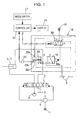
- Fig. 1 is a diagram illustrating a circuit structure according to a first embodiment of the present invention;
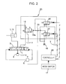
- Fig. 2 is a diagram illustrating a circuit structure according to a second embodiment of the present invention;
- Fig. 3 is a diagram illustrating a circuit structure according to a third embodiment of the present invention;
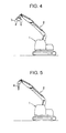
- Fig. 4 is a schematic side view of a crushing machine in which an opening/closing compression crusher is attached to an attachment;
- Fig. 5 is a schematic side view of the crushing machine in which a breaker is attached to the attachment; and
- Figs. 6A and 6B are diagrams illustrating the structure of a circuit that is switched with a manual directional control valve, where Fig. 6A shows a circuit state for compression crushing and Fig. 6B shows a circuit state for breaking.
- Figs. 4 and 5 illustrate a crushing machine including a hydraulic excavator as a base body and a hydraulic circuit for a working machine according to the present invention.
- The crushing machine includes a crawler
type base machine 1 and abendable attachment 2 mounted on thebase machine 1. In the embodiments described below, an opening/closing compression crusher 3 (see Fig. 4) called a nibbler and a vibrating breaker 4 (see Fig. 5) are explained as examples of working devices. - The opening/
closing compression crusher 3 called a nibbler or the vibratingbreaker 4 is attached to an end of theattachment 2 as a working device depending on the kind of work to be performed. - In this case, the
compression crusher 3 and thebreaker 4 use different hydraulic actuators, and the actuators must be provided with respective oil supply/discharge passages. Accordingly, a hydraulic circuit must be switched depending on the attached working device. - Hydraulic circuits for working machines according to embodiments of the present invention that provide a fail-safe function will be described below with reference to the accompanying drawings.
- Referring to Fig. 1, a directional
control valve unit 18 includes a hydraulic pilot-operated maindirectional control valve 19 that switches between a compression-crushing position a and a breaking position b and asolenoid valve 20 that switches themain valve 19 on the basis of an electric signal from acontroller 21 that functions as control means. Thesolenoid valve 20 switches between a position y for supplying a pilot pressure to themain valve 19 and a position x for shutting off the pilot pressure on the basis of the electric signal from thecontroller 21. - According to the present invention, detecting means detects the switch state of the
main valve 19 as the actual circuit state. Preferably, the detecting means is structured such that themain valve 19 included in the directionalcontrol valve unit 18 has a pressure port connected to a hydraulic power source at one end of themain valve 19 and a pressure sensor is connected to the pressure port. The detecting means may include, for example, apressure sensor 23 which will be described below. - In this case, since the state of the
main valve 19 included in the directionalcontrol valve unit 18 is detected as the actual circuit state, the structure of the detecting means can be made simple. In particular, when thepressure sensor 23 is used, thepressure sensor 23 simply detects whether or not a pressure is applied to the pressure port of themain valve 19. Therefore, the detecting means is small and inexpensive, and can easily be installed in the circuit. - The basic structure and operation (circuit-state-switching operation) performed by the directional
control valve unit 18 will be described below. - The
solenoid valve 20 switches between the compression-crushing position x at which the pilot pressure of a pilothydraulic power source 16 is not supplied to apilot port 19a of the main valve 19 (that is, for connecting theport 19a to a tank T) and the breaking position y at which the pilot pressure is supplied to thepilot port 19a. In this structure, when amode switch 17 as a switch for changing modes is switched to compression-crushing, thecontroller 21 does not transmit the electric signal to thesolenoid valve 20. Therefore, thesolenoid valve 20 and themain valve 19 are switched to the compression-crushing positions x and a, respectively, as shown in Fig. 1. - Accordingly, lines of the compression-crusher cylinder 9 are connected to a
hydraulic pump 8 and the tank T via a control valve 5 (circuit state for compression crushing). - When the
mode switch 17 is switched to breaking, thecontroller 21 transmits the electric signal to thesolenoid valve 20 so that thesolenoid valve 20 switches to the breaking position y. Therefore, themain valve 19 also switches to the breaking position b. - Accordingly, the return line of the
breaker cylinder 10 is directly connected to the tank T without passing through the control valve 5 (circuit state of for breaking). - In the first embodiment, the
main valve 19 included in the directionalcontrol valve unit 18 has a sub-spool 22 that moves together with a spool (main spool) of themain valve 19. - The
sub spool 22 has input andoutput ports tank port 22c. - The
input port 22a is connected to the pilothydraulic power source 16 and thetank port 22c is connected to the tank T. When themain valve 19 is switched from the compression-crushing position a shown in the figure to the breaking position b, the input andoutput ports hydraulic power source 16 is supplied to theoutput port 22b. - The
output port 22b is connected to thepressure sensor 23 and thepressure sensor 23 outputs a signal to thecontroller 21. - Accordingly, whether the
main valve 19 is at the compression-crushing position a or the breaking position b, that is, the actual circuit state, can be detected on the basis of whether or not the pressure is applied to theoutput port 22b. - In addition, the
controller 21 is connected to a display (lamp, buzzer, etc.) 24 that functions as display means. As is clear from the fact that a buzzer is mentioned as an example of thedisplay 24, thedisplay 24 is not limited to a visual display that can be presented on a screen or the like. For example, other means for attracting an attention, such as an alarm, may also be used as thedisplay 24 as long as the operator can be informed of the actual circuit state by the activateddisplay 24. - The
controller 21 compares the signal from thepressure sensor 23 that represents the actual circuit state with an operation signal of themode switch 17 that represents the circuit state expected by the operator. If the two signals do not match, that is, when the circuit is set for breaking even through compression crushing is selected by the operator or when the circuit is set for compression crushing even through breaking is selected by the operator, thedisplay 24 is activated. - Thus, when an abnormality like a line breakage occurs in a control system of the directional
control valve unit 18, the operator can be informed of the situation by the display. Accordingly, the operator can stop the operation of thecontrol valve 5 so that various troubles caused by the discrepancy between the expected and actual circuit states can be avoided. - In the above-described structure, a pressure switch may be used instead of the
pressure sensor 23. - In the first embodiment, the display is activated when the expected and actual circuit states do not match. In comparison, in a second embodiment, the operation of a compression-crusher cylinder 9 or a
breaker cylinder 10 is stopped automatically when an abnormality occurs. - According to the second embodiment, a directional
control valve unit 25 includes a hydraulic pilot-operated maindirectional control valve 19 and first andsecond solenoid valves controller 28 in accordance with the operation of amode switch 17. - The
solenoid valves hydraulic power source 16. When thefirst solenoid valve 26 is operated, a pilot pressure of the pilothydraulic power source 16 is supplied to apilot port 19a of themain valve 19 so that themain valve 19 is switched from a compression-crushing position a to a breaking position b. - In addition, when the
solenoid valves remote control valve 6 for controlling acontrol valve 5 via ashuttle valve 29 as a primary pressure. - In this structure, when the
solenoid valves remote control valve 6 via the operatedsolenoid valve control valve 5 is switched in accordance with the operation of theremote control valve 6 and the compression-crusher cylinder 9 or thebreaker cylinder 10 is operated. - However, if an abnormality like a breakage of electric lines connecting the
controller 28 to thesolenoid valves solenoid valves remote control valve 6 stops. - More specifically, if an abnormality occurs while breaking is selected, the
first solenoid valve 26 cannot be operated and the pilot pressure is not output from thesolenoid valve 26. Therefore, the primary pressure of theremote control valve 6 is shut off. - Similarly, if an abnormality occurs while compression crushing is selected by the
mode switch 17, thesecond solenoid valve 27 cannot be operated. Therefore, also in this case, the primary pressure of theremote control valve 6 is shut off. - Accordingly, the
control valve 5 cannot be operated even when theremote control valve 6 is operated (or thecontrol valve 5 returns to neutral if thecontrol valve 5 is being operated). As a result, the compression-crusher cylinder 9 or thebreaker cylinder 10 is automatically stopped, and thus the fail-safe function is provided. - According to the present embodiment, the
solenoid valves control valve unit 25 are used to shut off the primary pressure of theremote control valve 6. Therefore, the structure is simpler than that in the case in which, for example, an additional solenoid shutoff valve is provided at a primary side of theremote control valve 6 and the shutoff valve is operated when a fail is detected. - Thus, according to the present embodiment, operation-stopping means for stopping the operation of the compression-crusher cylinder 9 or the
breaker cylinder 10, which functions as a hydraulic actuator, is provided. Thecontroller 28 that functions as control means causes the operation-stopping means to stop the operation of the compression-crusher cylinder 9 or thebreaker cylinder 10 when the actual circuit state and the selected circuit state do not match. - Thus, when the actual and selected circuit states do not match, the operation of the compression-crusher cylinder 9 or the
breaker cylinder 10 can be automatically stopped by the operation-stopping means in addition to activating a display. Accordingly, the reliability of the fail-safe function can be increased. In addition, when the display and automatic stopping are performed simultaneously, the operator can reliably recognize the discrepancy between the expected and actual circuit states (occurrence of a fail). Therefore, recognition of the cause and repair can be facilitated. - In the third embodiment, the display function described in the first embodiment and the automatic stopping function described in the second embodiment are both performed when an abnormality occurs.
- More specifically, the circuit structure according to the first embodiment is basically applied, and an additional
solenoid shutoff valve 30 is provided at a primary side of aremote control valve 6. In this case, when the actual and expected circuit states do not match, in addition to activating adisplay 24, theshutoff valve 30 is activated by a signal from acontroller 21 so that the primary pressure of theremote control valve 6 is shut off. - Accordingly, since the
display 24 is activated and the operation of a hydraulic actuator (a compression-crusher cylinder 9 or a breaker cylinder 10) is automatically stopped simultaneously, the reliability of the fail-safe function can be increased. In addition, since the automatic stopping and display are simultaneously performed, the operator can reliably recognize the discrepancy between the expected and actual circuit states (occurrence of a fail). Therefore, recognition of the cause and repair can be facilitated. - In the above-described embodiments, the compression crusher and the breaker are explained as examples of working devices that can be selectively attached. However, other various combinations of devices can be applied as long as the devices are driven by different hydraulic actuators and it is necessary to switch the circuit state depending on the actuator to be used.
- Although the invention has been described with reference to the preferred embodiments in the attached figures, it is noted that equivalents may be employed and substitutions made herein without departing from the scope of the invention as recited in the claims.
Claims (8)
- A hydraulic circuit for a working machine including a base machine and an attachment mounted on the base machine, the hydraulic circuit comprising:control means that generates a signal depending on a selecting operation performed by an operator;hydraulic actuators for driving respective working devices, the hydraulic actuators being driven by a drive circuit having two kinds of circuit states that correspond to the working devices;a directional control valve unit which, when one of the working devices is attached to the attachment, switches in response to the signal from the control means to select one of the two kinds of circuit states;detecting means for detecting the actual circuit state; anddisplay means activated by the control means,wherein the control means activates the display means when the actual circuit state detected by the detecting means and the selected circuit state do not match.
- The hydraulic circuit according to claim 1, wherein the number of kinds of the working devices is two.
- The hydraulic circuit according to claim 1 or claim 2, wherein the directional control valve unit includes a hydraulic pilot-operated main directional control valve and a solenoid valve that switches between a position at which a pilot pressure is supplied to the main directional control valve and a position at which the pilot pressure is not supplied to the main directional control valve on the basis of an electric signal from the control means, and
wherein the detecting means detects a state of the main directional control valve as the actual circuit state. - The hydraulic circuit according to claim 3, wherein the main directional control valve included in the directional control valve unit has a pressure port connected to a hydraulic power source at one end of the main directional control valve and the detecting means detects a pressure at the pressure port as the actual circuit state.
- The hydraulic circuit according to any one of claims 1 to 4, further comprising:operation-stopping means for stopping the operation of the hydraulic actuators,wherein the control means causes the operation stop means to stop the operation of the hydraulic actuators when the actual circuit state and the selected circuit state do not match.
- The hydraulic circuit according to claim 5, further comprising:a hydraulic pilot-operated directional control valve that functions as a common control valve for controlling the operation of the hydraulic actuators for driving the working devices,wherein the operation-stopping means stops applying a pilot pressure to the common control valve.
- A hydraulic circuit for a working machine including a base machine and an attachment mounted on the base machine, the hydraulic circuit comprising:control means that generates a signal depending on a selecting operation performed by an operator;hydraulic actuators for respectively driving two kinds of working devices, the hydraulic actuators being driven by a drive circuit having two kinds of circuit states that correspond to the working devices;a directional control valve unit which, when one of the working devices is attached to the attachment, switches in response to the signal from the control means to select one of the two kinds of circuit states; and
a hydraulic pilot-operated directional control valve that functions as a common control valve for controlling the operation of the hydraulic actuators for driving the working devices and that is operated by a remote control valve,wherein the directional control valve unit includes a hydraulic pilot-operated main directional control valve that switches depending on whether a pilot pressure is supplied or shut off to generate the two kinds of circuit states and first and second solenoid valves that are selectively operated on the basis of an electric signal from the control means,wherein each of the solenoid valves is connected to the pilot hydraulic power source and supplies a pilot pressure from the pilot hydraulic power source to the main directional control valve when the solenoid valve is operated, andwherein the pilot pressure from the pilot hydraulic power source is supplied to the remote control valve that operates the common control valve as a primary pressure when the solenoid valves are operated. - A working machine comprising a base body having an attachment mounted thereon and a hydraulic circuit, wherein the hydraulic circuit is a circuit as claimed in any one of claims 1 to 7.
Applications Claiming Priority (1)
| Application Number | Priority Date | Filing Date | Title |
|---|---|---|---|
| JP2005181926A JP4281714B2 (en) | 2005-06-22 | 2005-06-22 | Hydraulic circuit of work machine |
Publications (3)
| Publication Number | Publication Date |
|---|---|
| EP1736672A2 true EP1736672A2 (en) | 2006-12-27 |
| EP1736672A3 EP1736672A3 (en) | 2011-11-09 |
| EP1736672B1 EP1736672B1 (en) | 2012-12-19 |
Family
ID=37052953
Family Applications (1)
| Application Number | Title | Priority Date | Filing Date |
|---|---|---|---|
| EP06115088A Not-in-force EP1736672B1 (en) | 2005-06-22 | 2006-06-07 | Hydraulic circuit for working machine |
Country Status (4)
| Country | Link |
|---|---|
| US (1) | US7478530B2 (en) |
| EP (1) | EP1736672B1 (en) |
| JP (1) | JP4281714B2 (en) |
| CN (1) | CN1884849B (en) |
Families Citing this family (14)
| Publication number | Priority date | Publication date | Assignee | Title |
|---|---|---|---|---|
| JP4458083B2 (en) * | 2006-11-27 | 2010-04-28 | コベルコ建機株式会社 | Relief pressure switching device for hydraulic work machine |
| JP4896775B2 (en) * | 2007-02-28 | 2012-03-14 | 日立建機株式会社 | Safety equipment for hydraulic work machines |
| JP4896774B2 (en) * | 2007-02-28 | 2012-03-14 | 日立建機株式会社 | Safety equipment for hydraulic work machines |
| US20090198409A1 (en) * | 2008-01-31 | 2009-08-06 | Caterpillar Inc. | Work tool data system |
| JP4953325B2 (en) * | 2009-03-12 | 2012-06-13 | キャタピラー エス エー アール エル | Work machine |
| JP4931955B2 (en) * | 2009-04-06 | 2012-05-16 | 日立建機株式会社 | Hydraulic circuit device of excavator |
| JP2011047211A (en) * | 2009-08-27 | 2011-03-10 | Hitachi Constr Mach Co Ltd | Attachment driving device of construction machine |
| US9835181B2 (en) * | 2013-04-22 | 2017-12-05 | Illinois Tool Works Inc. | Systems and methods for detecting a type of hydraulic device |
| GB2514112C (en) * | 2013-05-13 | 2016-11-30 | Caterpillar Inc | Valve Arrangement |
| EP3208495B1 (en) * | 2016-02-18 | 2021-07-07 | Takeuchi MFG.Co.,Ltd. | Control device for hydraulic traveling device |
| JP6621431B2 (en) * | 2017-03-06 | 2019-12-18 | 日立建機株式会社 | Hydraulic drive device for hydraulic excavator |
| US10912252B2 (en) | 2017-12-27 | 2021-02-09 | Cnh Industrial America Llc | Localized hydraulic circuit configuration detection and loading in a self-propelled agricultural product applicator |
| JP6687054B2 (en) * | 2018-03-29 | 2020-04-22 | コベルコ建機株式会社 | Swivel work machine |
| CN113152550B (en) * | 2021-04-07 | 2022-12-20 | 柳州柳工挖掘机有限公司 | Operation mode control system and method and excavator |
Citations (1)
| Publication number | Priority date | Publication date | Assignee | Title |
|---|---|---|---|---|
| JPH08199632A (en) | 1995-01-20 | 1996-08-06 | Hitachi Constr Mach Co Ltd | Hydraulic circuit of hydraulic excavator |
Family Cites Families (9)
| Publication number | Priority date | Publication date | Assignee | Title |
|---|---|---|---|---|
| US3583437A (en) * | 1969-09-29 | 1971-06-08 | Gaf Corp | Whiteprint duplicating machine liquid supply system |
| BE794710A (en) * | 1972-01-31 | 1973-05-16 | Knorr Bremse Gmbh | SAFETY CONTROL SYSTEM FOR PNEUMATIC OR HYDRAULIC CONTROL CIRCUIT |
| ES2166395T3 (en) * | 1994-05-13 | 2002-04-16 | Mcneilus Truck & Mfg Inc | HYDRAULIC LEAK DETECTION SYSTEM. |
| JPH08270021A (en) | 1995-03-31 | 1996-10-15 | Yutani Heavy Ind Ltd | Hydraulic circuit of construction machine |
| JP3210221B2 (en) * | 1995-10-11 | 2001-09-17 | 新キャタピラー三菱株式会社 | Construction machine control circuit |
| JP4155381B2 (en) * | 2000-10-06 | 2008-09-24 | 株式会社小松製作所 | Attachment control device for hydraulic excavator |
| JP4519315B2 (en) * | 2000-12-28 | 2010-08-04 | 株式会社小松製作所 | Construction equipment pressure oil flow control device |
| JP2002294758A (en) | 2001-03-29 | 2002-10-09 | Komatsu Ltd | Hydraulic circuit for work equipment |
| JP3732761B2 (en) * | 2001-07-06 | 2006-01-11 | 新キャタピラー三菱株式会社 | Control device for work equipment |
-
2005
- 2005-06-22 JP JP2005181926A patent/JP4281714B2/en not_active Expired - Lifetime
-
2006
- 2006-06-06 US US11/422,503 patent/US7478530B2/en active Active
- 2006-06-07 EP EP06115088A patent/EP1736672B1/en not_active Not-in-force
- 2006-06-22 CN CN2006100940563A patent/CN1884849B/en active Active
Patent Citations (1)
| Publication number | Priority date | Publication date | Assignee | Title |
|---|---|---|---|---|
| JPH08199632A (en) | 1995-01-20 | 1996-08-06 | Hitachi Constr Mach Co Ltd | Hydraulic circuit of hydraulic excavator |
Also Published As
| Publication number | Publication date |
|---|---|
| JP2007002462A (en) | 2007-01-11 |
| CN1884849B (en) | 2010-08-04 |
| US7478530B2 (en) | 2009-01-20 |
| US20060288863A1 (en) | 2006-12-28 |
| JP4281714B2 (en) | 2009-06-17 |
| CN1884849A (en) | 2006-12-27 |
| EP1736672A3 (en) | 2011-11-09 |
| EP1736672B1 (en) | 2012-12-19 |
Similar Documents
| Publication | Publication Date | Title |
|---|---|---|
| US7478530B2 (en) | Hydraulic circuit for working machine | |
| EP1790859B1 (en) | Hydraulic controller for working machine | |
| US10227090B2 (en) | Hydraulic drive system | |
| US20030089106A1 (en) | Hydraulic circuit | |
| EP3249117B1 (en) | Control system for construction machine | |
| US7594395B2 (en) | Hydraulic control device for working machine | |
| JP6225035B2 (en) | Fluid pressure system | |
| KR101045334B1 (en) | Hydraulic system for excavator's optional work tool control | |
| US10767668B2 (en) | Hydraulic control system for construction machine | |
| EP2799692A1 (en) | Engine control method of construction machine | |
| JP4819510B2 (en) | Hydraulic control device for work machine | |
| KR20100032471A (en) | Control valve of having floating function | |
| JP2744176B2 (en) | Work equipment safety equipment | |
| KR100479923B1 (en) | heavy equipment | |
| KR100611717B1 (en) | Heavy Equipment Hydraulic Circuit | |
| KR20200007678A (en) | Valve structure and construction machinery | |
| KR19980086021A (en) | Malfunction prevention device of hydraulic construction machine | |
| KR100713863B1 (en) | Emergency hydraulic pump control device | |
| JP3517828B2 (en) | Operating device for pilot operated switching valve | |
| JP2007277823A (en) | Emergency operating device for construction equipment | |
| JP2008014445A (en) | Working machine |
Legal Events
| Date | Code | Title | Description |
|---|---|---|---|
| PUAI | Public reference made under article 153(3) epc to a published international application that has entered the european phase |
Free format text: ORIGINAL CODE: 0009012 |
|
| 17P | Request for examination filed |
Effective date: 20060607 |
|
| AK | Designated contracting states |
Kind code of ref document: A2 Designated state(s): AT BE BG CH CY CZ DE DK EE ES FI FR GB GR HU IE IS IT LI LT LU LV MC NL PL PT RO SE SI SK TR |
|
| AX | Request for extension of the european patent |
Extension state: AL BA HR MK YU |
|
| PUAL | Search report despatched |
Free format text: ORIGINAL CODE: 0009013 |
|
| AK | Designated contracting states |
Kind code of ref document: A3 Designated state(s): AT BE BG CH CY CZ DE DK EE ES FI FR GB GR HU IE IS IT LI LT LU LV MC NL PL PT RO SE SI SK TR |
|
| AX | Request for extension of the european patent |
Extension state: AL BA HR MK RS |
|
| RIC1 | Information provided on ipc code assigned before grant |
Ipc: F15B 19/00 20060101ALI20110930BHEP Ipc: F15B 20/00 20060101AFI20110930BHEP |
|
| AKX | Designation fees paid |
Designated state(s): AT BE BG CH CY CZ DE DK EE ES FI FR GB GR HU IE IS IT LI LT LU LV MC NL PL PT RO SE SI SK TR |
|
| GRAP | Despatch of communication of intention to grant a patent |
Free format text: ORIGINAL CODE: EPIDOSNIGR1 |
|
| GRAS | Grant fee paid |
Free format text: ORIGINAL CODE: EPIDOSNIGR3 |
|
| GRAA | (expected) grant |
Free format text: ORIGINAL CODE: 0009210 |
|
| AK | Designated contracting states |
Kind code of ref document: B1 Designated state(s): AT BE BG CH CY CZ DE DK EE ES FI FR GB GR HU IE IS IT LI LT LU LV MC NL PL PT RO SE SI SK TR |
|
| REG | Reference to a national code |
Ref country code: GB Ref legal event code: FG4D |
|
| REG | Reference to a national code |
Ref country code: CH Ref legal event code: EP |
|
| REG | Reference to a national code |
Ref country code: AT Ref legal event code: REF Ref document number: 589576 Country of ref document: AT Kind code of ref document: T Effective date: 20130115 |
|
| REG | Reference to a national code |
Ref country code: DE Ref legal event code: R096 Ref document number: 602006033663 Country of ref document: DE Effective date: 20130221 |
|
| PG25 | Lapsed in a contracting state [announced via postgrant information from national office to epo] |
Ref country code: SE Free format text: LAPSE BECAUSE OF FAILURE TO SUBMIT A TRANSLATION OF THE DESCRIPTION OR TO PAY THE FEE WITHIN THE PRESCRIBED TIME-LIMIT Effective date: 20121219 Ref country code: FI Free format text: LAPSE BECAUSE OF FAILURE TO SUBMIT A TRANSLATION OF THE DESCRIPTION OR TO PAY THE FEE WITHIN THE PRESCRIBED TIME-LIMIT Effective date: 20121219 Ref country code: LT Free format text: LAPSE BECAUSE OF FAILURE TO SUBMIT A TRANSLATION OF THE DESCRIPTION OR TO PAY THE FEE WITHIN THE PRESCRIBED TIME-LIMIT Effective date: 20121219 Ref country code: ES Free format text: LAPSE BECAUSE OF FAILURE TO SUBMIT A TRANSLATION OF THE DESCRIPTION OR TO PAY THE FEE WITHIN THE PRESCRIBED TIME-LIMIT Effective date: 20130330 |
|
| REG | Reference to a national code |
Ref country code: NL Ref legal event code: VDEP Effective date: 20121219 Ref country code: AT Ref legal event code: MK05 Ref document number: 589576 Country of ref document: AT Kind code of ref document: T Effective date: 20121219 |
|
| REG | Reference to a national code |
Ref country code: LT Ref legal event code: MG4D |
|
| PG25 | Lapsed in a contracting state [announced via postgrant information from national office to epo] |
Ref country code: GR Free format text: LAPSE BECAUSE OF FAILURE TO SUBMIT A TRANSLATION OF THE DESCRIPTION OR TO PAY THE FEE WITHIN THE PRESCRIBED TIME-LIMIT Effective date: 20130320 Ref country code: SI Free format text: LAPSE BECAUSE OF FAILURE TO SUBMIT A TRANSLATION OF THE DESCRIPTION OR TO PAY THE FEE WITHIN THE PRESCRIBED TIME-LIMIT Effective date: 20121219 Ref country code: LV Free format text: LAPSE BECAUSE OF FAILURE TO SUBMIT A TRANSLATION OF THE DESCRIPTION OR TO PAY THE FEE WITHIN THE PRESCRIBED TIME-LIMIT Effective date: 20121219 |
|
| PG25 | Lapsed in a contracting state [announced via postgrant information from national office to epo] |
Ref country code: BG Free format text: LAPSE BECAUSE OF FAILURE TO SUBMIT A TRANSLATION OF THE DESCRIPTION OR TO PAY THE FEE WITHIN THE PRESCRIBED TIME-LIMIT Effective date: 20130319 Ref country code: BE Free format text: LAPSE BECAUSE OF FAILURE TO SUBMIT A TRANSLATION OF THE DESCRIPTION OR TO PAY THE FEE WITHIN THE PRESCRIBED TIME-LIMIT Effective date: 20121219 Ref country code: SK Free format text: LAPSE BECAUSE OF FAILURE TO SUBMIT A TRANSLATION OF THE DESCRIPTION OR TO PAY THE FEE WITHIN THE PRESCRIBED TIME-LIMIT Effective date: 20121219 Ref country code: EE Free format text: LAPSE BECAUSE OF FAILURE TO SUBMIT A TRANSLATION OF THE DESCRIPTION OR TO PAY THE FEE WITHIN THE PRESCRIBED TIME-LIMIT Effective date: 20121219 Ref country code: IS Free format text: LAPSE BECAUSE OF FAILURE TO SUBMIT A TRANSLATION OF THE DESCRIPTION OR TO PAY THE FEE WITHIN THE PRESCRIBED TIME-LIMIT Effective date: 20130419 Ref country code: AT Free format text: LAPSE BECAUSE OF FAILURE TO SUBMIT A TRANSLATION OF THE DESCRIPTION OR TO PAY THE FEE WITHIN THE PRESCRIBED TIME-LIMIT Effective date: 20121219 Ref country code: CZ Free format text: LAPSE BECAUSE OF FAILURE TO SUBMIT A TRANSLATION OF THE DESCRIPTION OR TO PAY THE FEE WITHIN THE PRESCRIBED TIME-LIMIT Effective date: 20121219 |
|
| PG25 | Lapsed in a contracting state [announced via postgrant information from national office to epo] |
Ref country code: NL Free format text: LAPSE BECAUSE OF FAILURE TO SUBMIT A TRANSLATION OF THE DESCRIPTION OR TO PAY THE FEE WITHIN THE PRESCRIBED TIME-LIMIT Effective date: 20121219 Ref country code: RO Free format text: LAPSE BECAUSE OF FAILURE TO SUBMIT A TRANSLATION OF THE DESCRIPTION OR TO PAY THE FEE WITHIN THE PRESCRIBED TIME-LIMIT Effective date: 20121219 Ref country code: PT Free format text: LAPSE BECAUSE OF FAILURE TO SUBMIT A TRANSLATION OF THE DESCRIPTION OR TO PAY THE FEE WITHIN THE PRESCRIBED TIME-LIMIT Effective date: 20130419 Ref country code: PL Free format text: LAPSE BECAUSE OF FAILURE TO SUBMIT A TRANSLATION OF THE DESCRIPTION OR TO PAY THE FEE WITHIN THE PRESCRIBED TIME-LIMIT Effective date: 20121219 |
|
| PLBE | No opposition filed within time limit |
Free format text: ORIGINAL CODE: 0009261 |
|
| STAA | Information on the status of an ep patent application or granted ep patent |
Free format text: STATUS: NO OPPOSITION FILED WITHIN TIME LIMIT |
|
| PG25 | Lapsed in a contracting state [announced via postgrant information from national office to epo] |
Ref country code: DK Free format text: LAPSE BECAUSE OF FAILURE TO SUBMIT A TRANSLATION OF THE DESCRIPTION OR TO PAY THE FEE WITHIN THE PRESCRIBED TIME-LIMIT Effective date: 20121219 |
|
| 26N | No opposition filed |
Effective date: 20130920 |
|
| PG25 | Lapsed in a contracting state [announced via postgrant information from national office to epo] |
Ref country code: CY Free format text: LAPSE BECAUSE OF FAILURE TO SUBMIT A TRANSLATION OF THE DESCRIPTION OR TO PAY THE FEE WITHIN THE PRESCRIBED TIME-LIMIT Effective date: 20121219 |
|
| REG | Reference to a national code |
Ref country code: DE Ref legal event code: R097 Ref document number: 602006033663 Country of ref document: DE Effective date: 20130920 |
|
| PG25 | Lapsed in a contracting state [announced via postgrant information from national office to epo] |
Ref country code: MC Free format text: LAPSE BECAUSE OF FAILURE TO SUBMIT A TRANSLATION OF THE DESCRIPTION OR TO PAY THE FEE WITHIN THE PRESCRIBED TIME-LIMIT Effective date: 20121219 |
|
| REG | Reference to a national code |
Ref country code: CH Ref legal event code: PL |
|
| REG | Reference to a national code |
Ref country code: IE Ref legal event code: MM4A |
|
| PG25 | Lapsed in a contracting state [announced via postgrant information from national office to epo] |
Ref country code: LI Free format text: LAPSE BECAUSE OF NON-PAYMENT OF DUE FEES Effective date: 20130630 Ref country code: IE Free format text: LAPSE BECAUSE OF NON-PAYMENT OF DUE FEES Effective date: 20130607 Ref country code: CH Free format text: LAPSE BECAUSE OF NON-PAYMENT OF DUE FEES Effective date: 20130630 |
|
| PG25 | Lapsed in a contracting state [announced via postgrant information from national office to epo] |
Ref country code: TR Free format text: LAPSE BECAUSE OF FAILURE TO SUBMIT A TRANSLATION OF THE DESCRIPTION OR TO PAY THE FEE WITHIN THE PRESCRIBED TIME-LIMIT Effective date: 20121219 |
|
| PG25 | Lapsed in a contracting state [announced via postgrant information from national office to epo] |
Ref country code: HU Free format text: LAPSE BECAUSE OF FAILURE TO SUBMIT A TRANSLATION OF THE DESCRIPTION OR TO PAY THE FEE WITHIN THE PRESCRIBED TIME-LIMIT; INVALID AB INITIO Effective date: 20060607 Ref country code: LU Free format text: LAPSE BECAUSE OF NON-PAYMENT OF DUE FEES Effective date: 20130607 |
|
| REG | Reference to a national code |
Ref country code: FR Ref legal event code: PLFP Year of fee payment: 11 |
|
| REG | Reference to a national code |
Ref country code: FR Ref legal event code: PLFP Year of fee payment: 12 |
|
| REG | Reference to a national code |
Ref country code: FR Ref legal event code: PLFP Year of fee payment: 13 |
|
| PGFP | Annual fee paid to national office [announced via postgrant information from national office to epo] |
Ref country code: IT Payment date: 20230510 Year of fee payment: 18 |
|
| PGFP | Annual fee paid to national office [announced via postgrant information from national office to epo] |
Ref country code: GB Payment date: 20240502 Year of fee payment: 19 |
|
| PGFP | Annual fee paid to national office [announced via postgrant information from national office to epo] |
Ref country code: DE Payment date: 20240502 Year of fee payment: 19 |
|
| PGFP | Annual fee paid to national office [announced via postgrant information from national office to epo] |
Ref country code: FR Payment date: 20240509 Year of fee payment: 19 |
|
| PG25 | Lapsed in a contracting state [announced via postgrant information from national office to epo] |
Ref country code: IT Free format text: LAPSE BECAUSE OF NON-PAYMENT OF DUE FEES Effective date: 20240607 |
|
| REG | Reference to a national code |
Ref country code: DE Ref legal event code: R119 Ref document number: 602006033663 Country of ref document: DE |
|
| GBPC | Gb: european patent ceased through non-payment of renewal fee |
Effective date: 20250607 |
|
| PG25 | Lapsed in a contracting state [announced via postgrant information from national office to epo] |
Ref country code: GB Free format text: LAPSE BECAUSE OF NON-PAYMENT OF DUE FEES Effective date: 20250607 |
|
| PG25 | Lapsed in a contracting state [announced via postgrant information from national office to epo] |
Ref country code: DE Free format text: LAPSE BECAUSE OF NON-PAYMENT OF DUE FEES Effective date: 20260101 |
|
| PG25 | Lapsed in a contracting state [announced via postgrant information from national office to epo] |
Ref country code: FR Free format text: LAPSE BECAUSE OF NON-PAYMENT OF DUE FEES Effective date: 20250630 |