EP1736636B1 - Hohle Turbinenschaufel - Google Patents
Hohle Turbinenschaufel Download PDFInfo
- Publication number
- EP1736636B1 EP1736636B1 EP06115887A EP06115887A EP1736636B1 EP 1736636 B1 EP1736636 B1 EP 1736636B1 EP 06115887 A EP06115887 A EP 06115887A EP 06115887 A EP06115887 A EP 06115887A EP 1736636 B1 EP1736636 B1 EP 1736636B1
- Authority
- EP
- European Patent Office
- Prior art keywords
- rim
- side wall
- blade
- wall
- indentation
- Prior art date
- Legal status (The legal status is an assumption and is not a legal conclusion. Google has not performed a legal analysis and makes no representation as to the accuracy of the status listed.)
- Active
Links
Images
Classifications
-
- F—MECHANICAL ENGINEERING; LIGHTING; HEATING; WEAPONS; BLASTING
- F01—MACHINES OR ENGINES IN GENERAL; ENGINE PLANTS IN GENERAL; STEAM ENGINES
- F01D—NON-POSITIVE DISPLACEMENT MACHINES OR ENGINES, e.g. STEAM TURBINES
- F01D5/00—Blades; Blade-carrying members; Heating, heat-insulating, cooling or antivibration means on the blades or the members
- F01D5/12—Blades
- F01D5/14—Form or construction
- F01D5/20—Specially-shaped blade tips to seal space between tips and stator
-
- Y—GENERAL TAGGING OF NEW TECHNOLOGICAL DEVELOPMENTS; GENERAL TAGGING OF CROSS-SECTIONAL TECHNOLOGIES SPANNING OVER SEVERAL SECTIONS OF THE IPC; TECHNICAL SUBJECTS COVERED BY FORMER USPC CROSS-REFERENCE ART COLLECTIONS [XRACs] AND DIGESTS
- Y02—TECHNOLOGIES OR APPLICATIONS FOR MITIGATION OR ADAPTATION AGAINST CLIMATE CHANGE
- Y02T—CLIMATE CHANGE MITIGATION TECHNOLOGIES RELATED TO TRANSPORTATION
- Y02T50/00—Aeronautics or air transport
- Y02T50/60—Efficient propulsion technologies, e.g. for aircraft
Definitions
- the invention relates to a hollow turbine engine blade and, more particularly, may relate to a hollow turbine gas turbine rotor blade, of the high pressure type, of a turbojet engine.
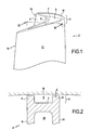
- the friction surfaces between the free end 3 of each blade and the annular surface of the turbine casing 16 which surrounds these vanes, as shown in FIG. figure 2 , are thus limited to the flanges 9 and 10 to protect the body of the blade and, more particularly, the bottom wall 7.
- the flanges 9 and 10 allow to optimize the clearance J between the free end of the blade 3 and the casing 16 and, thus, to limit the passage of gas from the lower surface to the extrados generating aerodynamic losses detrimental to the machine performance.
- cooling channels are generally provided for connecting the internal cooling passage 18 of the hollow blade to the open cavity 5 and thus to deliver fresh air to the flanges 9 and 10.
- the document EP 1 422 382 A2 presents a solution to improve the cooling of the extrados rim of a blade without a flange of intrados.
- This solution consists in making notches in the side wall of the extrados flange which faces the open cavity and is struck by the hot gases. Said indentations extend substantially from the base of the extrados flange to the upper end of this rim and cooling channels are drilled at the bottom of these notches to the internal cooling passage of the blade.
- These cuts have the main disadvantages of weakening the upper flange, especially its upper end, and to confine the fresh air, so that the wall portions between these cuts are not (or very badly) cooled.
- the drilling of the cooling channels can be a complex operation, requiring specific equipment.
- the invention aims to provide a hollow turbine engine blade, simple to manufacture, or the end edges are well cooled.
- the invention relates to a hollow turbine engine blade according to claim 1.
- the advantages of the invention are related, on the one hand, to the inclination of the side wall of the rim with respect to the direction orthogonal to the bottom wall, hereinafter considered as the vertical direction, and, on the other hand, on the other hand, that the cooling channels are provided at the base of the rim.
- This arrangement allows the fresh air escaping from the channels to follow the wall of the rim and thus form on this wall, a protective air film which protects the rim of the hot gases and cools it.
- the inclination of the side wall of the flange facilitates the drilling of the cooling channels: it is easy to pierce these channels, even in the vertical direction, because the space above the junction area between the bottom wall and sidewall is sufficiently clear to allow the passage of a tool (eg, an electrode) or a laser beam.
- a tool eg, an electrode
- drilling a channel at the base of a rim side wall forming an acute or right angle with the bottom wall is a long and delicate operation because care must be taken not to damage the side wall and not to pierce the canal too far from this wall.
- the blade is devoid of a flange of intrados extending the intrados wall or comprises only a portion of flange of intrados.
- the end of the blade has an end flange which extends between the leading edge and the trailing edge of the blade, set back from the underside side: it is It usually acts as an extrados rim along the extrados side, but it could be an intermediate rim between the inner and outer sides of the end of the blade.
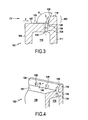
- the free end 103 of the blade 102 has, in the region shown, an extrados rim 110 but no underside flange.
- the side wall 120 of the extrados rim defines with the bottom wall 107 the open cavity 105. Due to the absence of a soffit flange, the side wall 120 is struck by the hot gases passing through the turbine, which cause the blades 102. With respect to the blade, these hot gases flow along the arrow F. The side wall 120 is therefore subjected to very high temperatures and must be effectively cooled.
- cooling channels 122 connect the internal cooling passage 118 of the blade 102 to the cavity 105 and open at the base of the flange 110, at the junction zone between this rim and the bottom wall 107. of the cavity 105.
- the side wall 120 and the bottom wall 107 have flat cross-sections, so that there is an edge 130 in the junction area between these walls. However, a rounding could be provided in this junction area.
- the channels 122 comprise two parts: an adjustment part formed by a hole 124 and a diffusion part 126 formed, on the one hand, by a cavity 128 made on the wall 120 of the rim at the outlet of the channel 122 and, on the other hand, by the extension of the bore 124.
- the adjustment part is thus called because the minimum section of the bore 124 affects the amount of fresh air passing through the channel 122.
- the diffusion portion 126 opens into the cavity 105 and communicates with the piercing 124.
- the piercing 124 opens on the one hand inside the diffusion part 126 and on the other hand inside passage 118.
- the bore 124 may be of cylindrical shape and is made, for example, by laser or electro-erosion drilling, at the base of the wall 120.
- the axis of the bore 124, shown in phantom, is orthogonal to the bottom wall 107.
- the side wall 120 of the flange 110 forms an obtuse angle A, strictly greater than 90 °, with the bottom wall 107, so that it does not interfere with the vertical drilling 124.
- the impression 128 is, in turn, formed partly on the wall 120 and partly inside the bore 124.
- This cavity 128 is formed, for example, by electroerosion using an electrode that the it comes to center on the piercing 124.
- This electrode can be of conical shape with a more or less rounded tip.
- the impression 128 has a contour of generally triangular shape and the bottom of this impression is curved and, more precisely, convex with respect to the axis of the piercing 124.
- the triangular outline widens the flow of air out of the bore 124 and thus widens the cooled sidewall surface 120.
- the impression 128 stops before the upper end of the flange 110 so as not to weaken it.
- the footprint 128 stops before or in the vicinity of the mid-height of the rim 110, so that the flow of fresh air fanned out of the imprints 128 is spread as much as possible on the wall 120.
- the distribution of the cooling channels 122 along the wall 120 is important to cool the wall well and, advantageously, the channels 122 are evenly distributed and are sufficiently close to each other to form a substantially continuous protective film along of the wall 120.
- the angle inclination A of the wall 120 is also important for the flow of fresh air leaving the channels 122 remains in contact with the wall 120. Also, the angle A is sufficiently small to that the flow of fresh air flowing along the arrow C, does not deviate from the wall 120 but, on the contrary, remains in contact.
- the angle A is large enough not to hinder the drilling of the channels 122, as explained above.
- the angle A formed between the side wall 120 of the flange 110 and the bottom wall 107 is between 110 ° and 135 ° and advantageously is around 120 °.
- the example of blade described above is simple to manufacture because, on the one hand, it is known to easily perform in the casting the inclined lateral wall 120 of the flange 110, so that no additional machining step is necessary. necessary. Then, the drilling of the cooling channels is facilitated by the inclination of the wall 120 and can be realized quickly, with common drilling techniques. The manufacture of such a dawn is therefore economical.
- the invention is not limited to a blade having a single extrados rim, but can be applied, for example, to a blade having an extrados rim and a portion only of a pressure flange, or still at a dawn having an intermediate rim that extends neither the intrados wall nor the extrados wall, but is located between the intrados and extrados side of the end of the blade.
- it is possible, thanks to the invention, to cool it by forming a film of fresh air against its side wall exposed to hot gases.
Claims (8)
- Hohle Turbomaschinenschaufel mit einem inneren Kühldurchgang (118), einem offenen Hohlraum (105), der sich am freien Ende der Schaufel befindet und durch eine bodenseitige Wand (107) und die Seitenwand (120) wenigstens eines Randes (110), der sich zwischen der Eintrittskante und der Austrittskante der Schaufel erstreckt, begrenzt ist, sowie mit wenigstens einem Kühlkanal (122), der den inneren Kühldurchgang mit dem offenen Hohlraum verbindet, wobei der Kühlkanal (122) an der Basis der Seitenwand des Randes (110) ausmündet, wobei diese Seitenwand (120) mit der genannten bodenseitigen Wand (107) einen stumpfen Winkel (A) bildet, der streng größer als 90° ist, wobei an dieser Seitenwand (120) am Ausgang des Kühlkanals (122) eine Einbuchtung (128) ausgebildet ist, dadurch gekennzeichnet, daß diese Einbuchtung (128) vor dem oberen Ende des Randes (110) aufhört.
- Hohle Schaufel nach Anspruch 1, dadurch gekennzeichnet, daß die erfindungsgemäße Schaufel keinen vorderseitigen Rand aufweist oder nur einen Abschnitt eines vorderseitigen Randes aufweist.
- Hohle Schaufel nach Anspruch 1 oder 2, dadurch gekennzeichnet, daß der zwischen der Seitenwand (120) und der bodenseitigen Wand (107) gebildete Winkel (A) zwischen 110 und 135° liegt und vorteilhafterweise etwa 120° beträgt.
- Hohle Schaufel nach irgendeinem der Ansprüche 1 bis 3, dadurch gekennzeichnet, daß die Kontur der Einbuchtung (128) allgemein dreieckförmig ist.
- Hohle Schaufel nach irgendeinem der Ansprüche 1 bis 4, dadurch gekennzeichnet, daß der Boden der Einbuchtung (128) gekrümmt ist.
- Hohle Schaufel nach irgendeinem der Ansprüche 1 bis 5, dadurch gekennzeichnet, daß der Kühlkanal (122) aus zwei Teilen besteht, nämlich einem Einstellteil, der von einer Bohrung (124) gebildet ist, und einem Diffusionsteil (126), der teilweise von der Einbuchtung (128) gebildet ist.
- Hohle Schaufel nach irgendeinem der Ansprüche 1 bis 6, dadurch gekennzeichnet, daß mehrere Kühlkanäle (122) gleichmäßig entlang der Seitenwand (120) verteilt sind.
- Hohle Schaufel nach irgendeinem der Ansprüche 1 bis 7, dadurch gekennzeichnet, daß die Einbuchtung (128) in der Nähe der halben Höhe des Randes (110) aufhört.
Applications Claiming Priority (1)
| Application Number | Priority Date | Filing Date | Title |
|---|---|---|---|
| FR0506442A FR2887581A1 (fr) | 2005-06-24 | 2005-06-24 | Aube creuse de turbomachine |
Publications (2)
| Publication Number | Publication Date |
|---|---|
| EP1736636A1 EP1736636A1 (de) | 2006-12-27 |
| EP1736636B1 true EP1736636B1 (de) | 2008-08-13 |
Family
ID=35169336
Family Applications (1)
| Application Number | Title | Priority Date | Filing Date |
|---|---|---|---|
| EP06115887A Active EP1736636B1 (de) | 2005-06-24 | 2006-06-22 | Hohle Turbinenschaufel |
Country Status (5)
| Country | Link |
|---|---|
| US (1) | US7530788B2 (de) |
| EP (1) | EP1736636B1 (de) |
| DE (1) | DE602006002186D1 (de) |
| FR (1) | FR2887581A1 (de) |
| RU (1) | RU2411367C2 (de) |
Families Citing this family (17)
| Publication number | Priority date | Publication date | Assignee | Title |
|---|---|---|---|---|
| US7510376B2 (en) * | 2005-08-25 | 2009-03-31 | General Electric Company | Skewed tip hole turbine blade |
| US8206108B2 (en) | 2007-12-10 | 2012-06-26 | Honeywell International Inc. | Turbine blades and methods of manufacturing |
| US8628299B2 (en) * | 2010-01-21 | 2014-01-14 | General Electric Company | System for cooling turbine blades |
| US8777567B2 (en) * | 2010-09-22 | 2014-07-15 | Honeywell International Inc. | Turbine blades, turbine assemblies, and methods of manufacturing turbine blades |
| US9951629B2 (en) * | 2012-07-03 | 2018-04-24 | United Technologies Corporation | Tip leakage flow directionality control |
| US9777582B2 (en) * | 2012-07-03 | 2017-10-03 | United Technologies Corporation | Tip leakage flow directionality control |
| US9957817B2 (en) | 2012-07-03 | 2018-05-01 | United Technologies Corporation | Tip leakage flow directionality control |
| US10408066B2 (en) | 2012-08-15 | 2019-09-10 | United Technologies Corporation | Suction side turbine blade tip cooling |
| GB201223193D0 (en) * | 2012-12-21 | 2013-02-06 | Rolls Royce Plc | Turbine blade |
| US9856739B2 (en) | 2013-09-18 | 2018-01-02 | Honeywell International Inc. | Turbine blades with tip portions having converging cooling holes |
| US9816389B2 (en) | 2013-10-16 | 2017-11-14 | Honeywell International Inc. | Turbine rotor blades with tip portion parapet wall cavities |
| US9879544B2 (en) | 2013-10-16 | 2018-01-30 | Honeywell International Inc. | Turbine rotor blades with improved tip portion cooling holes |
| US10107108B2 (en) | 2015-04-29 | 2018-10-23 | General Electric Company | Rotor blade having a flared tip |
| US10436038B2 (en) | 2015-12-07 | 2019-10-08 | General Electric Company | Turbine engine with an airfoil having a tip shelf outlet |
| CN109154200B (zh) * | 2016-05-24 | 2021-06-15 | 通用电气公司 | 涡轮发动机的翼型件和叶片,及对应的流动冷却流体的方法 |
| KR20190096569A (ko) * | 2018-02-09 | 2019-08-20 | 두산중공업 주식회사 | 가스 터빈 |
| US10787932B2 (en) | 2018-07-13 | 2020-09-29 | Honeywell International Inc. | Turbine blade with dust tolerant cooling system |
Family Cites Families (7)
| Publication number | Priority date | Publication date | Assignee | Title |
|---|---|---|---|---|
| US5348446A (en) * | 1993-04-28 | 1994-09-20 | General Electric Company | Bimetallic turbine airfoil |
| JP3137527B2 (ja) * | 1994-04-21 | 2001-02-26 | 三菱重工業株式会社 | ガスタービン動翼チップ冷却装置 |
| US6602052B2 (en) * | 2001-06-20 | 2003-08-05 | Alstom (Switzerland) Ltd | Airfoil tip squealer cooling construction |
| EP1281837A1 (de) * | 2001-07-24 | 2003-02-05 | ALSTOM (Switzerland) Ltd | Kühlvorrichtung für Turbinenschaufelspitzen |
| US6672829B1 (en) * | 2002-07-16 | 2004-01-06 | General Electric Company | Turbine blade having angled squealer tip |
| US6994514B2 (en) * | 2002-11-20 | 2006-02-07 | Mitsubishi Heavy Industries, Ltd. | Turbine blade and gas turbine |
| US6991430B2 (en) * | 2003-04-07 | 2006-01-31 | General Electric Company | Turbine blade with recessed squealer tip and shelf |
-
2005
- 2005-06-24 FR FR0506442A patent/FR2887581A1/fr not_active Withdrawn
-
2006
- 2006-06-22 EP EP06115887A patent/EP1736636B1/de active Active
- 2006-06-22 DE DE602006002186T patent/DE602006002186D1/de active Active
- 2006-06-23 US US11/473,020 patent/US7530788B2/en active Active
- 2006-06-23 RU RU2006122621/06A patent/RU2411367C2/ru active
Also Published As
| Publication number | Publication date |
|---|---|
| RU2411367C2 (ru) | 2011-02-10 |
| US20090092500A1 (en) | 2009-04-09 |
| FR2887581A1 (fr) | 2006-12-29 |
| DE602006002186D1 (de) | 2008-09-25 |
| EP1736636A1 (de) | 2006-12-27 |
| RU2006122621A (ru) | 2007-12-27 |
| US7530788B2 (en) | 2009-05-12 |
Similar Documents
| Publication | Publication Date | Title |
|---|---|---|
| EP1736636B1 (de) | Hohle Turbinenschaufel | |
| EP1726783B1 (de) | Hohle Laufschaufel für die Turbine eines Gasturbinentriebwerks, mit einem Hohlraum | |
| CA2716543C (fr) | Aube de turbine a extremite refroidie, et turbine et turbomachine associees | |
| EP2780551B1 (de) | Gasturbinenschaufel mit zur druckseite geneigtem kopf und mit kühlkanälen | |
| EP1741875B1 (de) | Kühlkreislauf für eine Rotorschaufel einer Turbomaschine | |
| CA2652679C (fr) | Aubes pour roue a aubes de turbomachine avec rainure pour le refroidissement | |
| EP1653047B1 (de) | Gasturbinenrotorschaufel | |
| FR2695163A1 (fr) | Aube creuse pour turbomachine et son procédé de fabrication. | |
| EP1790819A1 (de) | Kühlkreislauf einerTurbinenschaufel | |
| FR2867095A1 (fr) | Procede de fabrication d'une aube creuse pour turbomachine. | |
| EP2417024A1 (de) | Propeller für ein turbotriebwerk eines luftfahrzeugs mit einem um eine nabe herum angebrachten flügelhaltering | |
| FR2981979A1 (fr) | Roue de turbine pour une turbomachine | |
| FR2855439A1 (fr) | Procede de fabrication d'une aube creuse pour turbomachine. | |
| CA2806031A1 (fr) | Etancheite inter-aubes pour une roue de turbine ou de compresseur de turbomachine | |
| EP1630351A1 (de) | Schaufel eines Verdichters oder einer Gasturbine | |
| EP1481755B1 (de) | Verfahren zur Herstellung einer hohlen Schaufel für Strömungsmaschine | |
| EP4118304B1 (de) | Turbomaschinenhohlschaufel | |
| EP3317495A1 (de) | Hinterkantenturbinenschaufel mit ebenen bereichen | |
| FR3111661A1 (fr) | Aube de turbine avec système de refroidissement | |
| FR3106157A1 (fr) | Composant de turbomachine comportant des orifices de refroidissement ameliores | |
| WO2020193912A1 (fr) | Aube de turbomachine equipee d'un circuit de refroidissement et procede de fabrication a cire perdue d'une telle aube | |
| FR3116857A1 (fr) | composant de turbomachine comprenant une paroi pourvue de moyens de refroidissement | |
| EP3942158A1 (de) | Mit optimiertem kühlkreislauf ausgestattete turbinentriebwerksschaufel | |
| FR3128245A1 (fr) | Procede de fabrication d’une piece de rotor de turbomachine comprenant des portions arrondies optimisees et piece de turbomachine correspondante | |
| FR3101107A1 (fr) | Aube pour une turbomachine d’aeronef |
Legal Events
| Date | Code | Title | Description |
|---|---|---|---|
| PUAI | Public reference made under article 153(3) epc to a published international application that has entered the european phase |
Free format text: ORIGINAL CODE: 0009012 |
|
| 17P | Request for examination filed |
Effective date: 20060622 |
|
| AK | Designated contracting states |
Kind code of ref document: A1 Designated state(s): AT BE BG CH CY CZ DE DK EE ES FI FR GB GR HU IE IS IT LI LT LU LV MC NL PL PT RO SE SI SK TR |
|
| AX | Request for extension of the european patent |
Extension state: AL BA HR MK YU |
|
| AKX | Designation fees paid |
Designated state(s): DE FR GB |
|
| GRAP | Despatch of communication of intention to grant a patent |
Free format text: ORIGINAL CODE: EPIDOSNIGR1 |
|
| GRAS | Grant fee paid |
Free format text: ORIGINAL CODE: EPIDOSNIGR3 |
|
| GRAA | (expected) grant |
Free format text: ORIGINAL CODE: 0009210 |
|
| AK | Designated contracting states |
Kind code of ref document: B1 Designated state(s): DE FR GB |
|
| REG | Reference to a national code |
Ref country code: GB Ref legal event code: FG4D Free format text: NOT ENGLISH |
|
| REF | Corresponds to: |
Ref document number: 602006002186 Country of ref document: DE Date of ref document: 20080925 Kind code of ref document: P |
|
| PLBE | No opposition filed within time limit |
Free format text: ORIGINAL CODE: 0009261 |
|
| STAA | Information on the status of an ep patent application or granted ep patent |
Free format text: STATUS: NO OPPOSITION FILED WITHIN TIME LIMIT |
|
| 26N | No opposition filed |
Effective date: 20090514 |
|
| REG | Reference to a national code |
Ref country code: FR Ref legal event code: PLFP Year of fee payment: 11 |
|
| REG | Reference to a national code |
Ref country code: FR Ref legal event code: PLFP Year of fee payment: 12 |
|
| REG | Reference to a national code |
Ref country code: FR Ref legal event code: CD Owner name: SAFRAN AIRCRAFT ENGINES Effective date: 20170719 |
|
| REG | Reference to a national code |
Ref country code: FR Ref legal event code: PLFP Year of fee payment: 13 |
|
| REG | Reference to a national code |
Ref country code: DE Ref legal event code: R082 Ref document number: 602006002186 Country of ref document: DE Representative=s name: CBDL PATENTANWAELTE GBR, DE |
|
| PGFP | Annual fee paid to national office [announced via postgrant information from national office to epo] |
Ref country code: FR Payment date: 20230523 Year of fee payment: 18 Ref country code: DE Payment date: 20230523 Year of fee payment: 18 |
|
| PGFP | Annual fee paid to national office [announced via postgrant information from national office to epo] |
Ref country code: GB Payment date: 20230523 Year of fee payment: 18 |