EP1736303A2 - Technique for automatically analyzing Z-pin dynamic insertion data to determine if an automated acceptable insertion was performed - Google Patents
Technique for automatically analyzing Z-pin dynamic insertion data to determine if an automated acceptable insertion was performed Download PDFInfo
- Publication number
- EP1736303A2 EP1736303A2 EP06252945A EP06252945A EP1736303A2 EP 1736303 A2 EP1736303 A2 EP 1736303A2 EP 06252945 A EP06252945 A EP 06252945A EP 06252945 A EP06252945 A EP 06252945A EP 1736303 A2 EP1736303 A2 EP 1736303A2
- Authority
- EP
- European Patent Office
- Prior art keywords
- pins
- pin
- level
- insertion force
- speed
- Prior art date
- Legal status (The legal status is an assumption and is not a legal conclusion. Google has not performed a legal analysis and makes no representation as to the accuracy of the status listed.)
- Withdrawn
Links
- 238000003780 insertion Methods 0.000 title claims abstract description 218
- 230000037431 insertion Effects 0.000 title claims abstract description 217
- 238000000034 method Methods 0.000 title claims abstract description 123
- 239000002131 composite material Substances 0.000 claims abstract description 39
- 238000012544 monitoring process Methods 0.000 claims description 4
- 239000003351 stiffener Substances 0.000 description 30
- 238000007689 inspection Methods 0.000 description 15
- 239000000463 material Substances 0.000 description 9
- 239000012636 effector Substances 0.000 description 7
- 238000004519 manufacturing process Methods 0.000 description 5
- 238000005304 joining Methods 0.000 description 4
- 238000004891 communication Methods 0.000 description 3
- 229920000049 Carbon (fiber) Polymers 0.000 description 2
- 230000004888 barrier function Effects 0.000 description 2
- 239000004917 carbon fiber Substances 0.000 description 2
- 238000011161 development Methods 0.000 description 2
- 239000004619 high density foam Substances 0.000 description 2
- 239000004620 low density foam Substances 0.000 description 2
- 239000011159 matrix material Substances 0.000 description 2
- 238000011160 research Methods 0.000 description 2
- 229920005989 resin Polymers 0.000 description 2
- 239000011347 resin Substances 0.000 description 2
- XQUPVDVFXZDTLT-UHFFFAOYSA-N 1-[4-[[4-(2,5-dioxopyrrol-1-yl)phenyl]methyl]phenyl]pyrrole-2,5-dione Chemical compound O=C1C=CC(=O)N1C(C=C1)=CC=C1CC1=CC=C(N2C(C=CC2=O)=O)C=C1 XQUPVDVFXZDTLT-UHFFFAOYSA-N 0.000 description 1
- OKTJSMMVPCPJKN-UHFFFAOYSA-N Carbon Chemical compound [C] OKTJSMMVPCPJKN-UHFFFAOYSA-N 0.000 description 1
- 229920006231 aramid fiber Polymers 0.000 description 1
- 238000010276 construction Methods 0.000 description 1
- 238000001514 detection method Methods 0.000 description 1
- 238000009826 distribution Methods 0.000 description 1
- 230000005284 excitation Effects 0.000 description 1
- 230000008713 feedback mechanism Effects 0.000 description 1
- 239000000835 fiber Substances 0.000 description 1
- 239000002657 fibrous material Substances 0.000 description 1
- 239000003365 glass fiber Substances 0.000 description 1
- 229910002804 graphite Inorganic materials 0.000 description 1
- 239000010439 graphite Substances 0.000 description 1
- 238000002844 melting Methods 0.000 description 1
- 230000008018 melting Effects 0.000 description 1
- VNWKTOKETHGBQD-UHFFFAOYSA-N methane Chemical compound C VNWKTOKETHGBQD-UHFFFAOYSA-N 0.000 description 1
- 230000010355 oscillation Effects 0.000 description 1
- 229920003192 poly(bis maleimide) Polymers 0.000 description 1
- 229920000098 polyolefin Polymers 0.000 description 1
- 230000001105 regulatory effect Effects 0.000 description 1
- 238000012827 research and development Methods 0.000 description 1
- 238000012552 review Methods 0.000 description 1
- 229920001169 thermoplastic Polymers 0.000 description 1
- 239000004634 thermosetting polymer Substances 0.000 description 1
- 239000004416 thermosoftening plastic Substances 0.000 description 1
- 230000000007 visual effect Effects 0.000 description 1
Images




Classifications
-
- B—PERFORMING OPERATIONS; TRANSPORTING
- B29—WORKING OF PLASTICS; WORKING OF SUBSTANCES IN A PLASTIC STATE IN GENERAL
- B29C—SHAPING OR JOINING OF PLASTICS; SHAPING OF MATERIAL IN A PLASTIC STATE, NOT OTHERWISE PROVIDED FOR; AFTER-TREATMENT OF THE SHAPED PRODUCTS, e.g. REPAIRING
- B29C66/00—General aspects of processes or apparatus for joining preformed parts
- B29C66/40—General aspects of joining substantially flat articles, e.g. plates, sheets or web-like materials; Making flat seams in tubular or hollow articles; Joining single elements to substantially flat surfaces
- B29C66/47—Joining single elements to sheets, plates or other substantially flat surfaces
- B29C66/474—Joining single elements to sheets, plates or other substantially flat surfaces said single elements being substantially non-flat
-
- B—PERFORMING OPERATIONS; TRANSPORTING
- B29—WORKING OF PLASTICS; WORKING OF SUBSTANCES IN A PLASTIC STATE IN GENERAL
- B29C—SHAPING OR JOINING OF PLASTICS; SHAPING OF MATERIAL IN A PLASTIC STATE, NOT OTHERWISE PROVIDED FOR; AFTER-TREATMENT OF THE SHAPED PRODUCTS, e.g. REPAIRING
- B29C65/00—Joining or sealing of preformed parts, e.g. welding of plastics materials; Apparatus therefor
- B29C65/02—Joining or sealing of preformed parts, e.g. welding of plastics materials; Apparatus therefor by heating, with or without pressure
- B29C65/08—Joining or sealing of preformed parts, e.g. welding of plastics materials; Apparatus therefor by heating, with or without pressure using ultrasonic vibrations
-
- B—PERFORMING OPERATIONS; TRANSPORTING
- B29—WORKING OF PLASTICS; WORKING OF SUBSTANCES IN A PLASTIC STATE IN GENERAL
- B29C—SHAPING OR JOINING OF PLASTICS; SHAPING OF MATERIAL IN A PLASTIC STATE, NOT OTHERWISE PROVIDED FOR; AFTER-TREATMENT OF THE SHAPED PRODUCTS, e.g. REPAIRING
- B29C65/00—Joining or sealing of preformed parts, e.g. welding of plastics materials; Apparatus therefor
- B29C65/56—Joining or sealing of preformed parts, e.g. welding of plastics materials; Apparatus therefor using mechanical means or mechanical connections, e.g. form-fits
- B29C65/562—Joining or sealing of preformed parts, e.g. welding of plastics materials; Apparatus therefor using mechanical means or mechanical connections, e.g. form-fits using extra joining elements, i.e. which are not integral with the parts to be joined
- B29C65/564—Joining or sealing of preformed parts, e.g. welding of plastics materials; Apparatus therefor using mechanical means or mechanical connections, e.g. form-fits using extra joining elements, i.e. which are not integral with the parts to be joined hidden in the joint, e.g. dowels or Z-pins
-
- B—PERFORMING OPERATIONS; TRANSPORTING
- B29—WORKING OF PLASTICS; WORKING OF SUBSTANCES IN A PLASTIC STATE IN GENERAL
- B29C—SHAPING OR JOINING OF PLASTICS; SHAPING OF MATERIAL IN A PLASTIC STATE, NOT OTHERWISE PROVIDED FOR; AFTER-TREATMENT OF THE SHAPED PRODUCTS, e.g. REPAIRING
- B29C66/00—General aspects of processes or apparatus for joining preformed parts
- B29C66/01—General aspects dealing with the joint area or with the area to be joined
- B29C66/05—Particular design of joint configurations
- B29C66/10—Particular design of joint configurations particular design of the joint cross-sections
- B29C66/11—Joint cross-sections comprising a single joint-segment, i.e. one of the parts to be joined comprising a single joint-segment in the joint cross-section
- B29C66/112—Single lapped joints
-
- B—PERFORMING OPERATIONS; TRANSPORTING
- B29—WORKING OF PLASTICS; WORKING OF SUBSTANCES IN A PLASTIC STATE IN GENERAL
- B29C—SHAPING OR JOINING OF PLASTICS; SHAPING OF MATERIAL IN A PLASTIC STATE, NOT OTHERWISE PROVIDED FOR; AFTER-TREATMENT OF THE SHAPED PRODUCTS, e.g. REPAIRING
- B29C66/00—General aspects of processes or apparatus for joining preformed parts
- B29C66/01—General aspects dealing with the joint area or with the area to be joined
- B29C66/05—Particular design of joint configurations
- B29C66/10—Particular design of joint configurations particular design of the joint cross-sections
- B29C66/13—Single flanged joints; Fin-type joints; Single hem joints; Edge joints; Interpenetrating fingered joints; Other specific particular designs of joint cross-sections not provided for in groups B29C66/11 - B29C66/12
- B29C66/131—Single flanged joints, i.e. one of the parts to be joined being rigid and flanged in the joint area
-
- B—PERFORMING OPERATIONS; TRANSPORTING
- B29—WORKING OF PLASTICS; WORKING OF SUBSTANCES IN A PLASTIC STATE IN GENERAL
- B29C—SHAPING OR JOINING OF PLASTICS; SHAPING OF MATERIAL IN A PLASTIC STATE, NOT OTHERWISE PROVIDED FOR; AFTER-TREATMENT OF THE SHAPED PRODUCTS, e.g. REPAIRING
- B29C66/00—General aspects of processes or apparatus for joining preformed parts
- B29C66/50—General aspects of joining tubular articles; General aspects of joining long products, i.e. bars or profiled elements; General aspects of joining single elements to tubular articles, hollow articles or bars; General aspects of joining several hollow-preforms to form hollow or tubular articles
- B29C66/51—Joining tubular articles, profiled elements or bars; Joining single elements to tubular articles, hollow articles or bars; Joining several hollow-preforms to form hollow or tubular articles
- B29C66/52—Joining tubular articles, bars or profiled elements
- B29C66/524—Joining profiled elements
-
- B—PERFORMING OPERATIONS; TRANSPORTING
- B29—WORKING OF PLASTICS; WORKING OF SUBSTANCES IN A PLASTIC STATE IN GENERAL
- B29C—SHAPING OR JOINING OF PLASTICS; SHAPING OF MATERIAL IN A PLASTIC STATE, NOT OTHERWISE PROVIDED FOR; AFTER-TREATMENT OF THE SHAPED PRODUCTS, e.g. REPAIRING
- B29C66/00—General aspects of processes or apparatus for joining preformed parts
- B29C66/70—General aspects of processes or apparatus for joining preformed parts characterised by the composition, physical properties or the structure of the material of the parts to be joined; Joining with non-plastics material
- B29C66/72—General aspects of processes or apparatus for joining preformed parts characterised by the composition, physical properties or the structure of the material of the parts to be joined; Joining with non-plastics material characterised by the structure of the material of the parts to be joined
- B29C66/721—Fibre-reinforced materials
-
- B—PERFORMING OPERATIONS; TRANSPORTING
- B29—WORKING OF PLASTICS; WORKING OF SUBSTANCES IN A PLASTIC STATE IN GENERAL
- B29C—SHAPING OR JOINING OF PLASTICS; SHAPING OF MATERIAL IN A PLASTIC STATE, NOT OTHERWISE PROVIDED FOR; AFTER-TREATMENT OF THE SHAPED PRODUCTS, e.g. REPAIRING
- B29C66/00—General aspects of processes or apparatus for joining preformed parts
- B29C66/70—General aspects of processes or apparatus for joining preformed parts characterised by the composition, physical properties or the structure of the material of the parts to be joined; Joining with non-plastics material
- B29C66/73—General aspects of processes or apparatus for joining preformed parts characterised by the composition, physical properties or the structure of the material of the parts to be joined; Joining with non-plastics material characterised by the intensive physical properties of the material of the parts to be joined, by the optical properties of the material of the parts to be joined, by the extensive physical properties of the parts to be joined, by the state of the material of the parts to be joined or by the material of the parts to be joined being a thermoplastic or a thermoset
- B29C66/737—General aspects of processes or apparatus for joining preformed parts characterised by the composition, physical properties or the structure of the material of the parts to be joined; Joining with non-plastics material characterised by the intensive physical properties of the material of the parts to be joined, by the optical properties of the material of the parts to be joined, by the extensive physical properties of the parts to be joined, by the state of the material of the parts to be joined or by the material of the parts to be joined being a thermoplastic or a thermoset characterised by the state of the material of the parts to be joined
- B29C66/7375—General aspects of processes or apparatus for joining preformed parts characterised by the composition, physical properties or the structure of the material of the parts to be joined; Joining with non-plastics material characterised by the intensive physical properties of the material of the parts to be joined, by the optical properties of the material of the parts to be joined, by the extensive physical properties of the parts to be joined, by the state of the material of the parts to be joined or by the material of the parts to be joined being a thermoplastic or a thermoset characterised by the state of the material of the parts to be joined uncured, partially cured or fully cured
- B29C66/73751—General aspects of processes or apparatus for joining preformed parts characterised by the composition, physical properties or the structure of the material of the parts to be joined; Joining with non-plastics material characterised by the intensive physical properties of the material of the parts to be joined, by the optical properties of the material of the parts to be joined, by the extensive physical properties of the parts to be joined, by the state of the material of the parts to be joined or by the material of the parts to be joined being a thermoplastic or a thermoset characterised by the state of the material of the parts to be joined uncured, partially cured or fully cured the to-be-joined area of at least one of the parts to be joined being uncured, i.e. non cross-linked, non vulcanized
- B29C66/73752—General aspects of processes or apparatus for joining preformed parts characterised by the composition, physical properties or the structure of the material of the parts to be joined; Joining with non-plastics material characterised by the intensive physical properties of the material of the parts to be joined, by the optical properties of the material of the parts to be joined, by the extensive physical properties of the parts to be joined, by the state of the material of the parts to be joined or by the material of the parts to be joined being a thermoplastic or a thermoset characterised by the state of the material of the parts to be joined uncured, partially cured or fully cured the to-be-joined area of at least one of the parts to be joined being uncured, i.e. non cross-linked, non vulcanized the to-be-joined areas of both parts to be joined being uncured
-
- B—PERFORMING OPERATIONS; TRANSPORTING
- B29—WORKING OF PLASTICS; WORKING OF SUBSTANCES IN A PLASTIC STATE IN GENERAL
- B29C—SHAPING OR JOINING OF PLASTICS; SHAPING OF MATERIAL IN A PLASTIC STATE, NOT OTHERWISE PROVIDED FOR; AFTER-TREATMENT OF THE SHAPED PRODUCTS, e.g. REPAIRING
- B29C66/00—General aspects of processes or apparatus for joining preformed parts
- B29C66/80—General aspects of machine operations or constructions and parts thereof
- B29C66/82—Pressure application arrangements, e.g. transmission or actuating mechanisms for joining tools or clamps
- B29C66/824—Actuating mechanisms
- B29C66/8246—Servomechanisms, e.g. servomotors
-
- B—PERFORMING OPERATIONS; TRANSPORTING
- B29—WORKING OF PLASTICS; WORKING OF SUBSTANCES IN A PLASTIC STATE IN GENERAL
- B29C—SHAPING OR JOINING OF PLASTICS; SHAPING OF MATERIAL IN A PLASTIC STATE, NOT OTHERWISE PROVIDED FOR; AFTER-TREATMENT OF THE SHAPED PRODUCTS, e.g. REPAIRING
- B29C66/00—General aspects of processes or apparatus for joining preformed parts
- B29C66/80—General aspects of machine operations or constructions and parts thereof
- B29C66/83—General aspects of machine operations or constructions and parts thereof characterised by the movement of the joining or pressing tools
- B29C66/832—Reciprocating joining or pressing tools
- B29C66/8322—Joining or pressing tools reciprocating along one axis
-
- B—PERFORMING OPERATIONS; TRANSPORTING
- B29—WORKING OF PLASTICS; WORKING OF SUBSTANCES IN A PLASTIC STATE IN GENERAL
- B29C—SHAPING OR JOINING OF PLASTICS; SHAPING OF MATERIAL IN A PLASTIC STATE, NOT OTHERWISE PROVIDED FOR; AFTER-TREATMENT OF THE SHAPED PRODUCTS, e.g. REPAIRING
- B29C66/00—General aspects of processes or apparatus for joining preformed parts
- B29C66/80—General aspects of machine operations or constructions and parts thereof
- B29C66/84—Specific machine types or machines suitable for specific applications
- B29C66/863—Robotised, e.g. mounted on a robot arm
-
- B—PERFORMING OPERATIONS; TRANSPORTING
- B29—WORKING OF PLASTICS; WORKING OF SUBSTANCES IN A PLASTIC STATE IN GENERAL
- B29C—SHAPING OR JOINING OF PLASTICS; SHAPING OF MATERIAL IN A PLASTIC STATE, NOT OTHERWISE PROVIDED FOR; AFTER-TREATMENT OF THE SHAPED PRODUCTS, e.g. REPAIRING
- B29C66/00—General aspects of processes or apparatus for joining preformed parts
- B29C66/90—Measuring or controlling the joining process
- B29C66/92—Measuring or controlling the joining process by measuring or controlling the pressure, the force, the mechanical power or the displacement of the joining tools
- B29C66/922—Measuring or controlling the joining process by measuring or controlling the pressure, the force, the mechanical power or the displacement of the joining tools by measuring the pressure, the force, the mechanical power or the displacement of the joining tools
- B29C66/9221—Measuring or controlling the joining process by measuring or controlling the pressure, the force, the mechanical power or the displacement of the joining tools by measuring the pressure, the force, the mechanical power or the displacement of the joining tools by measuring the pressure, the force or the mechanical power
-
- B—PERFORMING OPERATIONS; TRANSPORTING
- B29—WORKING OF PLASTICS; WORKING OF SUBSTANCES IN A PLASTIC STATE IN GENERAL
- B29C—SHAPING OR JOINING OF PLASTICS; SHAPING OF MATERIAL IN A PLASTIC STATE, NOT OTHERWISE PROVIDED FOR; AFTER-TREATMENT OF THE SHAPED PRODUCTS, e.g. REPAIRING
- B29C66/00—General aspects of processes or apparatus for joining preformed parts
- B29C66/90—Measuring or controlling the joining process
- B29C66/92—Measuring or controlling the joining process by measuring or controlling the pressure, the force, the mechanical power or the displacement of the joining tools
- B29C66/924—Measuring or controlling the joining process by measuring or controlling the pressure, the force, the mechanical power or the displacement of the joining tools by controlling or regulating the pressure, the force, the mechanical power or the displacement of the joining tools
- B29C66/9241—Measuring or controlling the joining process by measuring or controlling the pressure, the force, the mechanical power or the displacement of the joining tools by controlling or regulating the pressure, the force, the mechanical power or the displacement of the joining tools by controlling or regulating the pressure, the force or the mechanical power
- B29C66/92441—Measuring or controlling the joining process by measuring or controlling the pressure, the force, the mechanical power or the displacement of the joining tools by controlling or regulating the pressure, the force, the mechanical power or the displacement of the joining tools by controlling or regulating the pressure, the force or the mechanical power the pressure, the force or the mechanical power being non-constant over time
- B29C66/92443—Measuring or controlling the joining process by measuring or controlling the pressure, the force, the mechanical power or the displacement of the joining tools by controlling or regulating the pressure, the force, the mechanical power or the displacement of the joining tools by controlling or regulating the pressure, the force or the mechanical power the pressure, the force or the mechanical power being non-constant over time following a pressure-time profile
-
- B—PERFORMING OPERATIONS; TRANSPORTING
- B29—WORKING OF PLASTICS; WORKING OF SUBSTANCES IN A PLASTIC STATE IN GENERAL
- B29C—SHAPING OR JOINING OF PLASTICS; SHAPING OF MATERIAL IN A PLASTIC STATE, NOT OTHERWISE PROVIDED FOR; AFTER-TREATMENT OF THE SHAPED PRODUCTS, e.g. REPAIRING
- B29C66/00—General aspects of processes or apparatus for joining preformed parts
- B29C66/90—Measuring or controlling the joining process
- B29C66/92—Measuring or controlling the joining process by measuring or controlling the pressure, the force, the mechanical power or the displacement of the joining tools
- B29C66/929—Measuring or controlling the joining process by measuring or controlling the pressure, the force, the mechanical power or the displacement of the joining tools characterized by specific pressure, force, mechanical power or displacement values or ranges
- B29C66/9292—Measuring or controlling the joining process by measuring or controlling the pressure, the force, the mechanical power or the displacement of the joining tools characterized by specific pressure, force, mechanical power or displacement values or ranges in explicit relation to another variable, e.g. pressure diagrams
- B29C66/92921—Measuring or controlling the joining process by measuring or controlling the pressure, the force, the mechanical power or the displacement of the joining tools characterized by specific pressure, force, mechanical power or displacement values or ranges in explicit relation to another variable, e.g. pressure diagrams in specific relation to time, e.g. pressure-time diagrams
-
- B—PERFORMING OPERATIONS; TRANSPORTING
- B29—WORKING OF PLASTICS; WORKING OF SUBSTANCES IN A PLASTIC STATE IN GENERAL
- B29C—SHAPING OR JOINING OF PLASTICS; SHAPING OF MATERIAL IN A PLASTIC STATE, NOT OTHERWISE PROVIDED FOR; AFTER-TREATMENT OF THE SHAPED PRODUCTS, e.g. REPAIRING
- B29C66/00—General aspects of processes or apparatus for joining preformed parts
- B29C66/90—Measuring or controlling the joining process
- B29C66/93—Measuring or controlling the joining process by measuring or controlling the speed
- B29C66/934—Measuring or controlling the joining process by measuring or controlling the speed by controlling or regulating the speed
- B29C66/93441—Measuring or controlling the joining process by measuring or controlling the speed by controlling or regulating the speed the speed being non-constant over time
-
- B—PERFORMING OPERATIONS; TRANSPORTING
- B29—WORKING OF PLASTICS; WORKING OF SUBSTANCES IN A PLASTIC STATE IN GENERAL
- B29C—SHAPING OR JOINING OF PLASTICS; SHAPING OF MATERIAL IN A PLASTIC STATE, NOT OTHERWISE PROVIDED FOR; AFTER-TREATMENT OF THE SHAPED PRODUCTS, e.g. REPAIRING
- B29C66/00—General aspects of processes or apparatus for joining preformed parts
- B29C66/90—Measuring or controlling the joining process
- B29C66/93—Measuring or controlling the joining process by measuring or controlling the speed
- B29C66/939—Measuring or controlling the joining process by measuring or controlling the speed characterised by specific speed values or ranges
-
- B—PERFORMING OPERATIONS; TRANSPORTING
- B29—WORKING OF PLASTICS; WORKING OF SUBSTANCES IN A PLASTIC STATE IN GENERAL
- B29C—SHAPING OR JOINING OF PLASTICS; SHAPING OF MATERIAL IN A PLASTIC STATE, NOT OTHERWISE PROVIDED FOR; AFTER-TREATMENT OF THE SHAPED PRODUCTS, e.g. REPAIRING
- B29C66/00—General aspects of processes or apparatus for joining preformed parts
- B29C66/90—Measuring or controlling the joining process
- B29C66/93—Measuring or controlling the joining process by measuring or controlling the speed
- B29C66/939—Measuring or controlling the joining process by measuring or controlling the speed characterised by specific speed values or ranges
- B29C66/9392—Measuring or controlling the joining process by measuring or controlling the speed characterised by specific speed values or ranges in explicit relation to another variable, e.g. speed diagrams
-
- B—PERFORMING OPERATIONS; TRANSPORTING
- B29—WORKING OF PLASTICS; WORKING OF SUBSTANCES IN A PLASTIC STATE IN GENERAL
- B29C—SHAPING OR JOINING OF PLASTICS; SHAPING OF MATERIAL IN A PLASTIC STATE, NOT OTHERWISE PROVIDED FOR; AFTER-TREATMENT OF THE SHAPED PRODUCTS, e.g. REPAIRING
- B29C66/00—General aspects of processes or apparatus for joining preformed parts
- B29C66/90—Measuring or controlling the joining process
- B29C66/96—Measuring or controlling the joining process characterised by the method for implementing the controlling of the joining process
- B29C66/961—Measuring or controlling the joining process characterised by the method for implementing the controlling of the joining process involving a feedback loop mechanism, e.g. comparison with a desired value
-
- B—PERFORMING OPERATIONS; TRANSPORTING
- B29—WORKING OF PLASTICS; WORKING OF SUBSTANCES IN A PLASTIC STATE IN GENERAL
- B29C—SHAPING OR JOINING OF PLASTICS; SHAPING OF MATERIAL IN A PLASTIC STATE, NOT OTHERWISE PROVIDED FOR; AFTER-TREATMENT OF THE SHAPED PRODUCTS, e.g. REPAIRING
- B29C66/00—General aspects of processes or apparatus for joining preformed parts
- B29C66/70—General aspects of processes or apparatus for joining preformed parts characterised by the composition, physical properties or the structure of the material of the parts to be joined; Joining with non-plastics material
- B29C66/72—General aspects of processes or apparatus for joining preformed parts characterised by the composition, physical properties or the structure of the material of the parts to be joined; Joining with non-plastics material characterised by the structure of the material of the parts to be joined
- B29C66/721—Fibre-reinforced materials
- B29C66/7212—Fibre-reinforced materials characterised by the composition of the fibres
-
- B—PERFORMING OPERATIONS; TRANSPORTING
- B29—WORKING OF PLASTICS; WORKING OF SUBSTANCES IN A PLASTIC STATE IN GENERAL
- B29C—SHAPING OR JOINING OF PLASTICS; SHAPING OF MATERIAL IN A PLASTIC STATE, NOT OTHERWISE PROVIDED FOR; AFTER-TREATMENT OF THE SHAPED PRODUCTS, e.g. REPAIRING
- B29C66/00—General aspects of processes or apparatus for joining preformed parts
- B29C66/70—General aspects of processes or apparatus for joining preformed parts characterised by the composition, physical properties or the structure of the material of the parts to be joined; Joining with non-plastics material
- B29C66/73—General aspects of processes or apparatus for joining preformed parts characterised by the composition, physical properties or the structure of the material of the parts to be joined; Joining with non-plastics material characterised by the intensive physical properties of the material of the parts to be joined, by the optical properties of the material of the parts to be joined, by the extensive physical properties of the parts to be joined, by the state of the material of the parts to be joined or by the material of the parts to be joined being a thermoplastic or a thermoset
- B29C66/739—General aspects of processes or apparatus for joining preformed parts characterised by the composition, physical properties or the structure of the material of the parts to be joined; Joining with non-plastics material characterised by the intensive physical properties of the material of the parts to be joined, by the optical properties of the material of the parts to be joined, by the extensive physical properties of the parts to be joined, by the state of the material of the parts to be joined or by the material of the parts to be joined being a thermoplastic or a thermoset characterised by the material of the parts to be joined being a thermoplastic or a thermoset
- B29C66/7392—General aspects of processes or apparatus for joining preformed parts characterised by the composition, physical properties or the structure of the material of the parts to be joined; Joining with non-plastics material characterised by the intensive physical properties of the material of the parts to be joined, by the optical properties of the material of the parts to be joined, by the extensive physical properties of the parts to be joined, by the state of the material of the parts to be joined or by the material of the parts to be joined being a thermoplastic or a thermoset characterised by the material of the parts to be joined being a thermoplastic or a thermoset characterised by the material of at least one of the parts being a thermoplastic
-
- B—PERFORMING OPERATIONS; TRANSPORTING
- B29—WORKING OF PLASTICS; WORKING OF SUBSTANCES IN A PLASTIC STATE IN GENERAL
- B29C—SHAPING OR JOINING OF PLASTICS; SHAPING OF MATERIAL IN A PLASTIC STATE, NOT OTHERWISE PROVIDED FOR; AFTER-TREATMENT OF THE SHAPED PRODUCTS, e.g. REPAIRING
- B29C66/00—General aspects of processes or apparatus for joining preformed parts
- B29C66/70—General aspects of processes or apparatus for joining preformed parts characterised by the composition, physical properties or the structure of the material of the parts to be joined; Joining with non-plastics material
- B29C66/73—General aspects of processes or apparatus for joining preformed parts characterised by the composition, physical properties or the structure of the material of the parts to be joined; Joining with non-plastics material characterised by the intensive physical properties of the material of the parts to be joined, by the optical properties of the material of the parts to be joined, by the extensive physical properties of the parts to be joined, by the state of the material of the parts to be joined or by the material of the parts to be joined being a thermoplastic or a thermoset
- B29C66/739—General aspects of processes or apparatus for joining preformed parts characterised by the composition, physical properties or the structure of the material of the parts to be joined; Joining with non-plastics material characterised by the intensive physical properties of the material of the parts to be joined, by the optical properties of the material of the parts to be joined, by the extensive physical properties of the parts to be joined, by the state of the material of the parts to be joined or by the material of the parts to be joined being a thermoplastic or a thermoset characterised by the material of the parts to be joined being a thermoplastic or a thermoset
- B29C66/7392—General aspects of processes or apparatus for joining preformed parts characterised by the composition, physical properties or the structure of the material of the parts to be joined; Joining with non-plastics material characterised by the intensive physical properties of the material of the parts to be joined, by the optical properties of the material of the parts to be joined, by the extensive physical properties of the parts to be joined, by the state of the material of the parts to be joined or by the material of the parts to be joined being a thermoplastic or a thermoset characterised by the material of the parts to be joined being a thermoplastic or a thermoset characterised by the material of at least one of the parts being a thermoplastic
- B29C66/73921—General aspects of processes or apparatus for joining preformed parts characterised by the composition, physical properties or the structure of the material of the parts to be joined; Joining with non-plastics material characterised by the intensive physical properties of the material of the parts to be joined, by the optical properties of the material of the parts to be joined, by the extensive physical properties of the parts to be joined, by the state of the material of the parts to be joined or by the material of the parts to be joined being a thermoplastic or a thermoset characterised by the material of the parts to be joined being a thermoplastic or a thermoset characterised by the material of at least one of the parts being a thermoplastic characterised by the materials of both parts being thermoplastics
-
- B—PERFORMING OPERATIONS; TRANSPORTING
- B29—WORKING OF PLASTICS; WORKING OF SUBSTANCES IN A PLASTIC STATE IN GENERAL
- B29C—SHAPING OR JOINING OF PLASTICS; SHAPING OF MATERIAL IN A PLASTIC STATE, NOT OTHERWISE PROVIDED FOR; AFTER-TREATMENT OF THE SHAPED PRODUCTS, e.g. REPAIRING
- B29C66/00—General aspects of processes or apparatus for joining preformed parts
- B29C66/70—General aspects of processes or apparatus for joining preformed parts characterised by the composition, physical properties or the structure of the material of the parts to be joined; Joining with non-plastics material
- B29C66/73—General aspects of processes or apparatus for joining preformed parts characterised by the composition, physical properties or the structure of the material of the parts to be joined; Joining with non-plastics material characterised by the intensive physical properties of the material of the parts to be joined, by the optical properties of the material of the parts to be joined, by the extensive physical properties of the parts to be joined, by the state of the material of the parts to be joined or by the material of the parts to be joined being a thermoplastic or a thermoset
- B29C66/739—General aspects of processes or apparatus for joining preformed parts characterised by the composition, physical properties or the structure of the material of the parts to be joined; Joining with non-plastics material characterised by the intensive physical properties of the material of the parts to be joined, by the optical properties of the material of the parts to be joined, by the extensive physical properties of the parts to be joined, by the state of the material of the parts to be joined or by the material of the parts to be joined being a thermoplastic or a thermoset characterised by the material of the parts to be joined being a thermoplastic or a thermoset
- B29C66/7394—General aspects of processes or apparatus for joining preformed parts characterised by the composition, physical properties or the structure of the material of the parts to be joined; Joining with non-plastics material characterised by the intensive physical properties of the material of the parts to be joined, by the optical properties of the material of the parts to be joined, by the extensive physical properties of the parts to be joined, by the state of the material of the parts to be joined or by the material of the parts to be joined being a thermoplastic or a thermoset characterised by the material of the parts to be joined being a thermoplastic or a thermoset characterised by the material of at least one of the parts being a thermoset
-
- B—PERFORMING OPERATIONS; TRANSPORTING
- B29—WORKING OF PLASTICS; WORKING OF SUBSTANCES IN A PLASTIC STATE IN GENERAL
- B29C—SHAPING OR JOINING OF PLASTICS; SHAPING OF MATERIAL IN A PLASTIC STATE, NOT OTHERWISE PROVIDED FOR; AFTER-TREATMENT OF THE SHAPED PRODUCTS, e.g. REPAIRING
- B29C66/00—General aspects of processes or apparatus for joining preformed parts
- B29C66/70—General aspects of processes or apparatus for joining preformed parts characterised by the composition, physical properties or the structure of the material of the parts to be joined; Joining with non-plastics material
- B29C66/73—General aspects of processes or apparatus for joining preformed parts characterised by the composition, physical properties or the structure of the material of the parts to be joined; Joining with non-plastics material characterised by the intensive physical properties of the material of the parts to be joined, by the optical properties of the material of the parts to be joined, by the extensive physical properties of the parts to be joined, by the state of the material of the parts to be joined or by the material of the parts to be joined being a thermoplastic or a thermoset
- B29C66/739—General aspects of processes or apparatus for joining preformed parts characterised by the composition, physical properties or the structure of the material of the parts to be joined; Joining with non-plastics material characterised by the intensive physical properties of the material of the parts to be joined, by the optical properties of the material of the parts to be joined, by the extensive physical properties of the parts to be joined, by the state of the material of the parts to be joined or by the material of the parts to be joined being a thermoplastic or a thermoset characterised by the material of the parts to be joined being a thermoplastic or a thermoset
- B29C66/7394—General aspects of processes or apparatus for joining preformed parts characterised by the composition, physical properties or the structure of the material of the parts to be joined; Joining with non-plastics material characterised by the intensive physical properties of the material of the parts to be joined, by the optical properties of the material of the parts to be joined, by the extensive physical properties of the parts to be joined, by the state of the material of the parts to be joined or by the material of the parts to be joined being a thermoplastic or a thermoset characterised by the material of the parts to be joined being a thermoplastic or a thermoset characterised by the material of at least one of the parts being a thermoset
- B29C66/73941—General aspects of processes or apparatus for joining preformed parts characterised by the composition, physical properties or the structure of the material of the parts to be joined; Joining with non-plastics material characterised by the intensive physical properties of the material of the parts to be joined, by the optical properties of the material of the parts to be joined, by the extensive physical properties of the parts to be joined, by the state of the material of the parts to be joined or by the material of the parts to be joined being a thermoplastic or a thermoset characterised by the material of the parts to be joined being a thermoplastic or a thermoset characterised by the material of at least one of the parts being a thermoset characterised by the materials of both parts being thermosets
-
- B—PERFORMING OPERATIONS; TRANSPORTING
- B29—WORKING OF PLASTICS; WORKING OF SUBSTANCES IN A PLASTIC STATE IN GENERAL
- B29C—SHAPING OR JOINING OF PLASTICS; SHAPING OF MATERIAL IN A PLASTIC STATE, NOT OTHERWISE PROVIDED FOR; AFTER-TREATMENT OF THE SHAPED PRODUCTS, e.g. REPAIRING
- B29C66/00—General aspects of processes or apparatus for joining preformed parts
- B29C66/90—Measuring or controlling the joining process
- B29C66/95—Measuring or controlling the joining process by measuring or controlling specific variables not covered by groups B29C66/91 - B29C66/94
- B29C66/959—Measuring or controlling the joining process by measuring or controlling specific variables not covered by groups B29C66/91 - B29C66/94 characterised by specific values or ranges of said specific variables
- B29C66/9592—Measuring or controlling the joining process by measuring or controlling specific variables not covered by groups B29C66/91 - B29C66/94 characterised by specific values or ranges of said specific variables in explicit relation to another variable, e.g. X-Y diagrams
-
- B—PERFORMING OPERATIONS; TRANSPORTING
- B29—WORKING OF PLASTICS; WORKING OF SUBSTANCES IN A PLASTIC STATE IN GENERAL
- B29L—INDEXING SCHEME ASSOCIATED WITH SUBCLASS B29C, RELATING TO PARTICULAR ARTICLES
- B29L2031/00—Other particular articles
- B29L2031/30—Vehicles, e.g. ships or aircraft, or body parts thereof
- B29L2031/3076—Aircrafts
-
- Y—GENERAL TAGGING OF NEW TECHNOLOGICAL DEVELOPMENTS; GENERAL TAGGING OF CROSS-SECTIONAL TECHNOLOGIES SPANNING OVER SEVERAL SECTIONS OF THE IPC; TECHNICAL SUBJECTS COVERED BY FORMER USPC CROSS-REFERENCE ART COLLECTIONS [XRACs] AND DIGESTS
- Y02—TECHNOLOGIES OR APPLICATIONS FOR MITIGATION OR ADAPTATION AGAINST CLIMATE CHANGE
- Y02T—CLIMATE CHANGE MITIGATION TECHNOLOGIES RELATED TO TRANSPORTATION
- Y02T50/00—Aeronautics or air transport
- Y02T50/40—Weight reduction
-
- Y—GENERAL TAGGING OF NEW TECHNOLOGICAL DEVELOPMENTS; GENERAL TAGGING OF CROSS-SECTIONAL TECHNOLOGIES SPANNING OVER SEVERAL SECTIONS OF THE IPC; TECHNICAL SUBJECTS COVERED BY FORMER USPC CROSS-REFERENCE ART COLLECTIONS [XRACs] AND DIGESTS
- Y10—TECHNICAL SUBJECTS COVERED BY FORMER USPC
- Y10T—TECHNICAL SUBJECTS COVERED BY FORMER US CLASSIFICATION
- Y10T29/00—Metal working
- Y10T29/49—Method of mechanical manufacture
- Y10T29/49764—Method of mechanical manufacture with testing or indicating
-
- Y—GENERAL TAGGING OF NEW TECHNOLOGICAL DEVELOPMENTS; GENERAL TAGGING OF CROSS-SECTIONAL TECHNOLOGIES SPANNING OVER SEVERAL SECTIONS OF THE IPC; TECHNICAL SUBJECTS COVERED BY FORMER USPC CROSS-REFERENCE ART COLLECTIONS [XRACs] AND DIGESTS
- Y10—TECHNICAL SUBJECTS COVERED BY FORMER USPC
- Y10T—TECHNICAL SUBJECTS COVERED BY FORMER US CLASSIFICATION
- Y10T29/00—Metal working
- Y10T29/49—Method of mechanical manufacture
- Y10T29/49764—Method of mechanical manufacture with testing or indicating
- Y10T29/49771—Quantitative measuring or gauging
-
- Y—GENERAL TAGGING OF NEW TECHNOLOGICAL DEVELOPMENTS; GENERAL TAGGING OF CROSS-SECTIONAL TECHNOLOGIES SPANNING OVER SEVERAL SECTIONS OF THE IPC; TECHNICAL SUBJECTS COVERED BY FORMER USPC CROSS-REFERENCE ART COLLECTIONS [XRACs] AND DIGESTS
- Y10—TECHNICAL SUBJECTS COVERED BY FORMER USPC
- Y10T—TECHNICAL SUBJECTS COVERED BY FORMER US CLASSIFICATION
- Y10T29/00—Metal working
- Y10T29/49—Method of mechanical manufacture
- Y10T29/49764—Method of mechanical manufacture with testing or indicating
- Y10T29/49771—Quantitative measuring or gauging
- Y10T29/49774—Quantitative measuring or gauging by vibratory or oscillatory movement
-
- Y—GENERAL TAGGING OF NEW TECHNOLOGICAL DEVELOPMENTS; GENERAL TAGGING OF CROSS-SECTIONAL TECHNOLOGIES SPANNING OVER SEVERAL SECTIONS OF THE IPC; TECHNICAL SUBJECTS COVERED BY FORMER USPC CROSS-REFERENCE ART COLLECTIONS [XRACs] AND DIGESTS
- Y10—TECHNICAL SUBJECTS COVERED BY FORMER USPC
- Y10T—TECHNICAL SUBJECTS COVERED BY FORMER US CLASSIFICATION
- Y10T29/00—Metal working
- Y10T29/49—Method of mechanical manufacture
- Y10T29/49764—Method of mechanical manufacture with testing or indicating
- Y10T29/49778—Method of mechanical manufacture with testing or indicating with aligning, guiding, or instruction
- Y10T29/4978—Assisting assembly or disassembly
-
- Y—GENERAL TAGGING OF NEW TECHNOLOGICAL DEVELOPMENTS; GENERAL TAGGING OF CROSS-SECTIONAL TECHNOLOGIES SPANNING OVER SEVERAL SECTIONS OF THE IPC; TECHNICAL SUBJECTS COVERED BY FORMER USPC CROSS-REFERENCE ART COLLECTIONS [XRACs] AND DIGESTS
- Y10—TECHNICAL SUBJECTS COVERED BY FORMER USPC
- Y10T—TECHNICAL SUBJECTS COVERED BY FORMER US CLASSIFICATION
- Y10T29/00—Metal working
- Y10T29/49—Method of mechanical manufacture
- Y10T29/49826—Assembling or joining
- Y10T29/49833—Punching, piercing or reaming part by surface of second part
-
- Y—GENERAL TAGGING OF NEW TECHNOLOGICAL DEVELOPMENTS; GENERAL TAGGING OF CROSS-SECTIONAL TECHNOLOGIES SPANNING OVER SEVERAL SECTIONS OF THE IPC; TECHNICAL SUBJECTS COVERED BY FORMER USPC CROSS-REFERENCE ART COLLECTIONS [XRACs] AND DIGESTS
- Y10—TECHNICAL SUBJECTS COVERED BY FORMER USPC
- Y10T—TECHNICAL SUBJECTS COVERED BY FORMER US CLASSIFICATION
- Y10T29/00—Metal working
- Y10T29/49—Method of mechanical manufacture
- Y10T29/49826—Assembling or joining
- Y10T29/49947—Assembling or joining by applying separate fastener
-
- Y—GENERAL TAGGING OF NEW TECHNOLOGICAL DEVELOPMENTS; GENERAL TAGGING OF CROSS-SECTIONAL TECHNOLOGIES SPANNING OVER SEVERAL SECTIONS OF THE IPC; TECHNICAL SUBJECTS COVERED BY FORMER USPC CROSS-REFERENCE ART COLLECTIONS [XRACs] AND DIGESTS
- Y10—TECHNICAL SUBJECTS COVERED BY FORMER USPC
- Y10T—TECHNICAL SUBJECTS COVERED BY FORMER US CLASSIFICATION
- Y10T29/00—Metal working
- Y10T29/53—Means to assemble or disassemble
- Y10T29/5343—Means to drive self-piercing work part
Definitions
- the present invention relates generally to reinforced composites, and more particularly, to a two-speed insertion process for Z-pinning/joining uncured composite laminates to each other.
- composites as primary structures in aerospace applications is becoming increasingly widespread in the aerospace industry.
- Traditional composite materials are made up of a resin matrix material and a quantity of two-dimensional fibers, continuous in the X-Y axis direction, but laminated in layers to produce a material thickness.
- Composite material construction wherein a fiber material such as a glass fiber, carbon fiber, or aramid fiber is combined with a matrix material, such as thermoplastic or thermoset resins, is an example of a traditional two-dimensional structure.
- stiffeners supply rigidity and stiffness that is required under certain flight load conditions.
- One typical stiffener is referred to as a hat stiffener.
- Hat stiffeners named for their shape, are typically applied to aerospace structural composite components via their skin.
- composite hat stiffeners were attached to composite skins with conventional mechanical fasteners.
- the hat stiffeners were co-cured to the skin of the structural composite material concurrently with the curing with the structural composite material itself.
- the failure mode typically occurred at the inner hat stiffener to skin surface.
- Z-pinning is now frequently used in the aerospace industry to facilitate the attachment of one or more stiffeners to a composite skin.
- the hat stiffeners and skin are able to be joined to each other prior to being cured. Joining composite parts together with Z-pins offers several advantages over conventional mechanical fasteners, such as lighter weight, more even distribution of the load, lowers costs, and co-curing of the two parts.
- a Z-pin carrier pre-form is disposed on that surface of the hat stiffener which is to be secured to the skin of the underlying structural composite material or laminate.
- the pre-form typically comprises contiguous layers of low and high density foam having a multiplicity of Z-pins embedded therein.
- the Z-pins are forced from the carrier pre-form through the hat stiffener and into the underlying laminate using a device such as a hydraulic press or an ultrasonic device (e.g., an ultrasonically excited horn) which uses high frequency energy to vibrate the Z-pins within the carrier pre-form to force them through the stiffener and into the underlying laminate.
- the key variables for automated insertion are insertion speed, insertion force, material age, material thickness, amount of laminate hot debulking, amplitude of the excitation of the horn (when an ultrasonic horn is used), the load bearing capability of the Z-pins, and insertion time. Inserting the Z-pins too fast results in excessive force being applied to the pins, thereby crushing them, or causing them not to penetrate completely through the parts being joined.
- Inserting the Z-pins too slowly takes excessive time thereby not achieving a reasonable return on investment, or causes the pre-form to overheat which creates a potential for a fire hazard.
- increasing the amplitude of the horn oscillation allows for faster insertion, but increases the risk for transferring too much energy into the pre-form causing over-insertion of the Z-pins and melting of the pre-form.
- one set of conditions may be fine for a new material and a thin total thickness, but not optimal for an aged material (e.g., a thirty day age material) that is of a maximum thickness.
- the height of the Z-pin carrier pre-form is measured upon the completion of the insertion process through the use of a simple gage to determine if the Z-pins were pressed far enough into the composite laminate to reach full depth.
- the definition of full depth in this case means that the Z-pins have fully penetrated the composite laminate and reached the bond tool surface.
- an additional visual check is performed to verify that the Z-pins did in fact penetrate the composite laminate ply closest to the tool surface. It is contemplated that a similar manual inspection process may be implemented in relation to the automated Z-pin insertion process/system described in Serial No. 11/158,400 to verify that the Z-pins were inserted to full depth.
- a system for facilitating a two speed insertion process for Z-pinning/joining uncured composite laminates to each other employs the use of an ultrasonic horn which is used to deliver ultrasonic energy to the Z-pins within a Z-pin carrier pre-form.
- the insertion speed is changed to a lower insertion speed based on the force resistance encountered during insertion, providing a tactile feedback system. No operator intervention is needed as the system adapts to the prevailing conditions.
- the insertion process of the present invention effectively varies one or more of the above-described variables or parameters based on conditions that exist during the Z-pin insertion process.
- the process of the present invention effectively ignores the initial conditions or parameters of material age and thickness, in favor of monitoring the force applied to drive the Z-pins into the laminate and using this information to vary the insertion speed.
- the Z-pins are initially inserted at a rate of 0.25 inches per second, with the insertion speed immediately being dropped to 0.050 inches per second when the insertion force reaches forty (40) pounds. When the insertion force reaches fifty (50) pounds, it is assumed that the Z-pins are all the way through the laminate and contacting a hard tool surface (or barrier sheet).
- the moment the ultrasonic horn contacts the pre-form is detected, with the readings for the first ten percent of the insertion being ignored to prevent false triggering. Additionally, production system safety conditions are also monitored as a back-up to the possibility that the fifty pound force trigger is not recognized during the insertion process.
- Other safety features which may be employed into the process of the present invention to terminate the insertion process include the length of time of insertion and the maximum distance traveled by the ultrasonic horn. If the maximum preset time is reached, the insertion is terminated. Similarly, if the maximum preset depth is reached the insertion is also terminated.
- One additional safety feature may involve remotely monitoring the temperature of the insertion horn. If the horn temperature exceeds a given threshold, the insertion process is stopped following the current insertion, and the horn allowed to cool before proceeding with further insertions.
- the automated insertion process of the present invention employs the use of a set of universal insertion parameters, which in turn facilitate the implementation of a two-speed insertion process based on certain insertion force thresholds.
- the automated inspection technique of the present invention automatically checks to see if the insertion speed has dropped to the requisite lower level, and further whether the requisite final insertion force was achieved during the insertion process. These particular parameters are automatically checked by analyzing data as it is generated during the insertion process.
- the automated inspection technique relies on the principle that an acceptable insertion is always produced when the insertion speed is reduced from the rate of 0.25 inches per second by achieving the forty pound insertion force threshold and the fifty pound insertion force limit threshold is also reached.
- the first condition may be met, but the two conditions are never met.
- FIGS. 1 and 1A provide cross-sectional and top perspective views, respectively, of an exemplary Z-pin carrier pre-form 10 which may be used in the Z-pinning process of the present invention as will be described in more detail below.
- the carrier pre-form 10 comprises an upper layer 12 of low density foam and a lower layer 14 of high density foam which is contiguous with the upper layer 12.
- the top surface of the lower layer 14 is abutted against the bottom surface of the upper layer 12.
- Covering the top surface of the upper layer 12 is a layer 16 of polyolefin.
- the layer 16 is in turn covered by a layer 18 which is fabricated from paper. As such, the layer 16 is disposed between the layer 18 and the upper layer 12.
- the carrier pre-form 10 includes a multiplicity of Z-pins 20 which are embedded within the upper and lower layers 12, 14. More particularly, the Z-pins 20 extend generally perpendicularly between the top surface of the upper layer 12 (which is covered by the layer 16) and the exposed bottom surface of the lower layer 14. The Z-pins 20 also preferably extend in spaced, generally parallel relation to each other, and may be embedded within the upper and lower layers 12, 14 in any one of a multiplicity of prescribed patterns. Thus, the particular pattern or arrangement of Z-pins 20 as is shown in Figure 1 is exemplary only in that the number, spacing and overall arrangement of the Z-pins 20 within the upper and lower layers 12, 14 is application specific.
- the carrier pre-form 10 has a generally rectangular configuration with a length L of approximately 12 inches, a width W of approximately 1.1 inches, and a height H of approximately 0.5 inches.
- the configuration of the carrier pre-form 10 as shown in Figure 1A is also exemplary only in that such carrier pre-form 10 may be provided in any one of a multiplicity of different configurations depending on the particular application.
- An exemplary carrier pre-form 10 is provided under the trademark Z-FiberTM from Aztex, Inc.
- the Z-pinning system and process of the present invention is suited for use in joining uncured composite laminates to each other.
- a typical application for the insertion system and process of the present invention is the attachment of a composite hat stiffener 22 to an underlying composite laminate 24.
- the hat stiffener 22 includes an elongate, enlarged central portion 26, and a pair of flange portions 28 which are integrally connected to and extend along respective sides of the central portion 26.
- Each flange portion 28 has a bottom surface which extends along and in contact with the top surface of the laminate 24.
- each flange portion 28 includes a top surface which extends at a slight angle relative to the top surface of the laminate 24.
- the angle of the top surface of each flange portion 28 relative to the top surface of the laminate 24 as shown in Figures 2 and 2A is approximately twelve degrees.
- the system 29 includes an ultrasonic horn 30 which is shown with particularity in Figures 4A and 4B.
- the ultrasonic horn 30 includes a converter 32 which is operatively coupled to a booster 34.
- the booster 34 is in turn operatively coupled to an insertion horn 36, the distal end of which defines a generally planar anvil 38.
- the system 29 includes a load cell 40 which is disposed adjacent to the converter 32 of the ultrasonic horn 30 and is in electrical communication with a programmable logic controller (PLC) 42.
- PLC programmable logic controller
- the PLC 42 is also in electrical communication with an ultrasonic power source 44, which in turn electrically communicates with the converter 32 of the ultrasonic horn 30.
- the PLC 42 is outfitted with a HMI interface 46 which in turn communicates with a robot controller 48.
- the robot controller 48 electrically communicates with a multi-axis robot 50 which is operatively coupled to the ultrasonic horn 30 in a manner wherein the robot 50 is able to control and regulate the movement of the ultrasonic horn 30 relative to the composite laminates which are to be secured to each other through the use of the insertion/Z-pinning process of the present invention.
- carrier pre-forms 10 will initially be positioned upon the top surfaces of the flange portions 28 of the hat stiffener 22.
- the robot 50 maneuvers a robot end effector of the robot 50 to a prescribed location or position relative to one of the carrier pre-forms 10.
- Disposed in the end effector are the ultrasonic horn 30, a single axis servo motor or drive 54, and drivers for the PLC 42.
- the anvil 38 of the ultrasonic horn 30 is maneuvered to a first position P1 (shown in Figure 2A) which is approximately 0.200 inches above one of the carrier pre-forms 10.
- the robot controller 48 then "freezes" the position of the robot 50 and passes control of the insertion process to the PLC 42.
- the PLC 42 communicates with the single axis drive 54 of the end effector in a manner causing the drive 54 to move the anvil 38 to a second position P2 which is approximately 0.100 inches above the adjacent carrier pre-form 10.
- the movement of the anvil 38 to the second position P2 triggers the start of the insertion process of the Z-pins 20 from within the carrier pre-form 10 through the corresponding flange portion 28 of the hat stiffener 22 and into the underlying laminate 24.
- the ultrasonic horn 30 is moved downwardly along a vertical axis Z (shown in Figure 2A) by the end effector (and in particular the drive 54) such that the anvil 38 comes into direct contact with a portion of the carrier pre-form 10.
- the end effector and in particular the drive 54
- the ultrasonic horn 30 is moved toward the carrier pre-form 10
- the moment that the anvil 38 touches the carrier pre-form 10 and approximately a three pound force is measured by the load cell 40
- ultrasonic energy is turned on and the insertion process continues.
- the downward movement along the axis Z is continued so as to cause the anvil 38 to exert/maintain downward pressure to those Z-pins 20 of the carrier pre-form 10 which are positioned directly below the anvil 38.
- the combination of mechanical motion (i.e., the downward movement of the ultrasonic horn 30 along the axis Z) and ultrasonic energy generated by the ultrasonic horn 30 effectively drives the Z-pins 20 from the carrier pre-form 10 into and through the hat stiffener 22.
- the force applied to the carrier pre-form 10 by the anvil 38 to drive the Z-pins 20 through the corresponding flange portion 28 of the hat stiffener 22 and into the underlying laminate 24 is monitored by the load cell 40 which, as indicated above, is in electrical communication with the PLC 42.
- the data transmitted to the PLC 42 by the load cell 40 is used to vary the insertion speed of the Z-pins 20.
- the insertion speed corresponds to the rate of travel of the ultrasonic horn 30, and hence the anvil 38, downwardly along the axis Z, such rate of travel be governed by the drive 54 which is controlled by the PLC 42.
- the ultrasonic horn 30 is actuated downwardly along the axis Z by the drive 54 such that the anvil 38 acts against certain ones of the Z-pins 20 of the adjacent carrier pre-form 10 in a manner causing them to be initially inserted through the corresponding flange portion 28 and into the underlying laminate 24 at a rate of approximately 0.25 inches per second.
- the insertion rate of the Z-pins 20 at approximately 0.25 inches per second typically takes place over a first distance D1 which is shown in Figure 2A.
- the load cell 40 When the data transmitted by the load cell 40 to the PLC 42 indicates that the amount of insertion force being applied by the ultrasonic horn 30 to the Z-pins 20 reaches approximately forty pounds, the downward rate of travel of the ultrasonic horn 30 along the axis Z by the drive 54, and hence the insertion speed, is immediately dropped to approximately 0.050 inches per second.
- the insertion rate of the Z-pins 20 at approximately 0.050 inches per second typically takes place over a second distance D2 which is also shown in Figure 2A.
- the load cell 40 continues to transmit data to the PLC 42 representative of the level of downward force being applied to the Z-pins 20 within the carrier pre-form 10 by the anvil 38.
- the variability in the insertion speed as described above in relation to the Z-pinning/insertion process of the present invention is regulated by servo loop software 52 which is programmed into the PLC 42.
- the servo loop software 52 is adapted to regulate the function of the drive 54, and precisely controls/regulates the movement of the ultrasonic horn 30 and hence the anvil 38 upwardly and downwardly along the axis Z.
- the PLC 42 passes control back to the robot controller 48 for positioning the end effector of the robot 50 for the next insertion.
- Servo loop feedback 56 transmitted to the servo loop software 52 by the servo motor 54 is, in conjunction with the data transmitted to the PLC 42 and hence the servo loop software 52 by the load cell 40, used to facilitate the above-described two-speed insertion process and to provide certain safety features which will be discussed in more detail below.
- the servo loop feedback 56 and data transmitted by the load cell 40 collectively provide a tactile feedback mechanism which effectively regulates the insertion process in the above-described manner.
- the Z-pin insertion system 29 shown in Figure 3 may be outfitted with components which allow for the detection of the moment when the anvil 38 defined by the insertion horn 36 contacts the pre-form 10.
- the servo loop software 52 programmed into the PLC 42 may be adapted to ignore the readings (i.e., the data transmitted from the load cell 40 and/or the servo loop feedback 56) for approximately the first ten percent of the insertion of the Z-pins 20 to prevent false triggering.
- certain production system safety conditions may be monitored as a back-up in the event the fifty pound force trigger which would otherwise terminate the insertion process is not recognized by the PLC 42.
- Other safety features which may be integrated into the system 29 (e.g., programmed into the PLC 42) to terminate the insertion process include the length of time of insertion and the maximum distance along the axis Z traveled by the ultrasonic horn 30 and hence the anvil 38. In this regard, if a maximum preset time is reached, the insertion may be terminated. Similarly, if a maximum preset depth is reached as dictated by the travel distance of the anvil 38 along the axis Z, the insertion may also be terminated.
- the temperature of the insertion horn 36 may be monitored as an additional safety feature. In this regard, if the temperature of the insertion horn 36 exceeds a given threshold, the insertion process for the Z-pins 20 may be stopped following the current insertion, with the insertion horn 36 being allowed to cool before proceeding with further insertions.
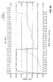
- the insertion graph depicted in Figure 5 may also be used as a record that the Z-pins 20 fully penetrated the flange portions 28 of the hat stiffener 22 and the underlying laminate 24, thereby eliminating any need for manual inspection by an inspector.
- a software program could also be written and programmed into the PLC 42 to automatically determine whether all the Z-pin insertions were good (i.e., fully penetrated), with a message being sent to the operator that all the insertions were good, or an error message being recorded for later review should any of the insertions not meet the software criteria of the servo loop software 52.
- the automated insertion process of the present invention employs the use of a set of universal insertion parameters, which in turn facilitate the implementation of a two-speed insertion process based on certain insertion force thresholds.
- the automated inspection technique of the present invention automatically checks to see if the insertion speed has dropped from the initial rate of approximately 0.25 inches per second to the requisite lower level of approximately 0.050 inches per second attributable to the insertion force applied by the ultrasonic horn 30 to the Z-pins 20 reaching about forty pounds, and further whether the requisite final insertion force of about fifty pounds was achieved during the insertion process.
- These particular parameters are automatically checked by analyzing data as it is generated during the insertion process. As explained above, such data is generated by the load cell 40 and transmitted to the PLC 42.
- the automated inspection technique of the present invention relies on the principle that an acceptable insertion is always produced when 1) the insertion speed is reduced from the initial rate of approximately 0.25 inches per second to the requisite lower level of approximately 0.050 inches per second, and 2) the insertion force limit threshold of approximately fifty pounds is also reached.
- the first condition (1) may be met, but both conditions (1 and 2) are never met.
- Figures 6A and 6D depict interrelationships which are indicative of acceptable insertions
- Figures 6B, 6C and 6E depicting interrelationships which are indicative of unacceptable insertions.
- the PLC 42 will be programmed to provide a signal which alerts the operator of the robot 50 that an unacceptable insertion has occurred, and/or provide an alert message in the insertion data generated by the insertion system 29 for quality purposes.
- manual inspections for full depth insertion of the Z-pins 20 may be eliminated from the production process, thus providing substantial cost savings.
Landscapes
- Engineering & Computer Science (AREA)
- Mechanical Engineering (AREA)
- Robotics (AREA)
- Lining Or Joining Of Plastics Or The Like (AREA)
- Moulding By Coating Moulds (AREA)
- Automatic Assembly (AREA)
Abstract
Description
- The present application is a continuation-in-part of
U.S. Application Serial No. 11/158,400 - The invention disclosed in the present application was developed under a contract research and development (CRAD) program funded by the Office of Naval Research (ONR).
- The present invention relates generally to reinforced composites, and more particularly, to a two-speed insertion process for Z-pinning/joining uncured composite laminates to each other.
- The use of composites as primary structures in aerospace applications is becoming increasingly widespread in the aerospace industry. Traditional composite materials are made up of a resin matrix material and a quantity of two-dimensional fibers, continuous in the X-Y axis direction, but laminated in layers to produce a material thickness. Composite material construction, wherein a fiber material such as a glass fiber, carbon fiber, or aramid fiber is combined with a matrix material, such as thermoplastic or thermoset resins, is an example of a traditional two-dimensional structure.
- Many structural composites, such as structural composite air frames, usually include multiple stiffeners. The stiffeners supply rigidity and stiffness that is required under certain flight load conditions. One typical stiffener is referred to as a hat stiffener. Hat stiffeners, named for their shape, are typically applied to aerospace structural composite components via their skin.
- Historically, composite hat stiffeners were attached to composite skins with conventional mechanical fasteners. In another attachment process sometimes employed, the hat stiffeners were co-cured to the skin of the structural composite material concurrently with the curing with the structural composite material itself. However, in both this process and that wherein the hat stiffeners were mechanically bolted and/or adhesively bonded to the skin, the failure mode typically occurred at the inner hat stiffener to skin surface.
- In order to resolve the occurrences of failure using the aforementioned attachment processes, Z-pinning is now frequently used in the aerospace industry to facilitate the attachment of one or more stiffeners to a composite skin. In this regard, with the development of Z-pins, methods for supporting the Z-pins in a carrier, and methods for inserting the Z-pins into uncured composite materials, the hat stiffeners and skin are able to be joined to each other prior to being cured. Joining composite parts together with Z-pins offers several advantages over conventional mechanical fasteners, such as lighter weight, more even distribution of the load, lowers costs, and co-curing of the two parts. In one currently employed Z-pinning process used in conjunction with hat stiffeners, a Z-pin carrier pre-form is disposed on that surface of the hat stiffener which is to be secured to the skin of the underlying structural composite material or laminate. The pre-form typically comprises contiguous layers of low and high density foam having a multiplicity of Z-pins embedded therein. The Z-pins are forced from the carrier pre-form through the hat stiffener and into the underlying laminate using a device such as a hydraulic press or an ultrasonic device (e.g., an ultrasonically excited horn) which uses high frequency energy to vibrate the Z-pins within the carrier pre-form to force them through the stiffener and into the underlying laminate.
- For purposes of achieving greater efficiencies and economies in the Z-pinning process, it is highly desirable to facilitate the insertion of the Z-pins automatically through the use of a robot. However, attempts at automating the Z-pinning process have proven challenging due to the need for special techniques to accommodate the many variables involved with the Z-pinning process. More particularly, the key variables for automated insertion are insertion speed, insertion force, material age, material thickness, amount of laminate hot debulking, amplitude of the excitation of the horn (when an ultrasonic horn is used), the load bearing capability of the Z-pins, and insertion time. Inserting the Z-pins too fast results in excessive force being applied to the pins, thereby crushing them, or causing them not to penetrate completely through the parts being joined. Inserting the Z-pins too slowly takes excessive time thereby not achieving a reasonable return on investment, or causes the pre-form to overheat which creates a potential for a fire hazard. When an ultrasonic horn is used, increasing the amplitude of the horn oscillation allows for faster insertion, but increases the risk for transferring too much energy into the pre-form causing over-insertion of the Z-pins and melting of the pre-form. Moreover, one set of conditions may be fine for a new material and a thin total thickness, but not optimal for an aged material (e.g., a thirty day age material) that is of a maximum thickness. Indeed, since many of the aforementioned variables interact in a non-linear fashion, it is extremely difficult to predict insertion success with any given combination. As an additional restriction, the insertion time is required to be fast enough to generate a good return on investment for the process. Thus, for automated Z-pin insertion in a production environment, there exists a need in the art for a single set of insertion parameters (universal parameters) which accommodate all the variations likely to be encountered within the specifications.
- The need for a single set of insertion parameters for use in an automated Z-pin insertion process is addressed by Applicant's co-pending
U.S. Application Serial No. 11/158,400 11/158,400 - In accordance with the present invention, there is provided a system for facilitating a two speed insertion process for Z-pinning/joining uncured composite laminates to each other. The insertion process of the present invention employs the use of an ultrasonic horn which is used to deliver ultrasonic energy to the Z-pins within a Z-pin carrier pre-form. In the insertion process, the insertion speed is changed to a lower insertion speed based on the force resistance encountered during insertion, providing a tactile feedback system. No operator intervention is needed as the system adapts to the prevailing conditions. By using this two speed process, it is possible to insert Z-pins into a wider variety of composite laminate conditions that would be impossible using single speed insertion techniques.
- The insertion process of the present invention effectively varies one or more of the above-described variables or parameters based on conditions that exist during the Z-pin insertion process. The process of the present invention effectively ignores the initial conditions or parameters of material age and thickness, in favor of monitoring the force applied to drive the Z-pins into the laminate and using this information to vary the insertion speed. In one embodiment of the present invention, the Z-pins are initially inserted at a rate of 0.25 inches per second, with the insertion speed immediately being dropped to 0.050 inches per second when the insertion force reaches forty (40) pounds. When the insertion force reaches fifty (50) pounds, it is assumed that the Z-pins are all the way through the laminate and contacting a hard tool surface (or barrier sheet).
- As part of the insertion process of the present invention, the moment the ultrasonic horn contacts the pre-form is detected, with the readings for the first ten percent of the insertion being ignored to prevent false triggering. Additionally, production system safety conditions are also monitored as a back-up to the possibility that the fifty pound force trigger is not recognized during the insertion process. Other safety features which may be employed into the process of the present invention to terminate the insertion process include the length of time of insertion and the maximum distance traveled by the ultrasonic horn. If the maximum preset time is reached, the insertion is terminated. Similarly, if the maximum preset depth is reached the insertion is also terminated. One additional safety feature may involve remotely monitoring the temperature of the insertion horn. If the horn temperature exceeds a given threshold, the insertion process is stopped following the current insertion, and the horn allowed to cool before proceeding with further insertions.
- Further in accordance with the present invention, there is provided a technique which may be used in conjunction with the automated insertion process described above to automatically perform a required full depth inspection and alert the robot operator should a non-acceptable insertion occur. As indicated above, the automated insertion process of the present invention employs the use of a set of universal insertion parameters, which in turn facilitate the implementation of a two-speed insertion process based on certain insertion force thresholds. The automated inspection technique of the present invention automatically checks to see if the insertion speed has dropped to the requisite lower level, and further whether the requisite final insertion force was achieved during the insertion process. These particular parameters are automatically checked by analyzing data as it is generated during the insertion process. More particularly, the automated inspection technique relies on the principle that an acceptable insertion is always produced when the insertion speed is reduced from the rate of 0.25 inches per second by achieving the forty pound insertion force threshold and the fifty pound insertion force limit threshold is also reached. For unacceptable Z-pin insertions, the first condition may be met, but the two conditions are never met. These, as well as other features of the present invention, will be described in more detail below.
- These, as well as other features of the present invention, will become more apparent upon reference to the drawings wherein:
- Figure 1 is a cross-sectional view of an exemplary Z-pin carrier pre-form having a multiplicity of Z-pins embedded therein;
- Figure 1A is a top perspective view of the Z-pin carrier pre-form shown in Figure 1;
- Figure 2 is a cross-sectional view illustrating the manner in which carrier pre-forms are positioned upon a hat stiffener for securing the hat stiffener to an underlying laminate through the use of the insertion system and process of the present invention;
- Figure 2A is an enlargement of the encircled region 2 shown in Figure 2, further illustrating a portion of the ultrasonic horn of the insertion system and its orientation relative to one of the pre-forms during the insertion process;
- Figure 3 is a schematic depiction of the various components included in the insertion system used to facilitate the insertion process of the present invention;
- Figures 4A and 4B are side and end views, respectively, of the ultrasonic horn of the insertion system used to facilitate the insertion process of the present invention;
- Figure 5 is a graphical depiction illustrating the interrelationship between insertion force and insertion speed achieved through the use of the insertion process of the present invention; and
- Figures 6A-6E are graphical depictions illustrating the interrelationship between insertion force and insertion speed as it pertains to acceptable and unacceptable Z-pin insertions facilitated through the use of the insertion process of the present invention.
- Referring now to the drawings wherein the showings are for purposes of illustrating preferred embodiments of the present invention only, and not for purposes of limiting the same, Figures 1 and 1A provide cross-sectional and top perspective views, respectively, of an exemplary Z-pin carrier pre-form 10 which may be used in the Z-pinning process of the present invention as will be described in more detail below. The carrier pre-form 10 comprises an
upper layer 12 of low density foam and alower layer 14 of high density foam which is contiguous with theupper layer 12. In this regard, the top surface of thelower layer 14 is abutted against the bottom surface of theupper layer 12. Covering the top surface of theupper layer 12 is alayer 16 of polyolefin. Thelayer 16 is in turn covered by alayer 18 which is fabricated from paper. As such, thelayer 16 is disposed between thelayer 18 and theupper layer 12. - In addition to the
layers carrier pre-form 10 includes a multiplicity of Z-pins 20 which are embedded within the upper andlower layers pins 20 extend generally perpendicularly between the top surface of the upper layer 12 (which is covered by the layer 16) and the exposed bottom surface of thelower layer 14. The Z-pins 20 also preferably extend in spaced, generally parallel relation to each other, and may be embedded within the upper andlower layers pins 20 as is shown in Figure 1 is exemplary only in that the number, spacing and overall arrangement of the Z-pins 20 within the upper andlower layers pins 20 is graphite, with the Z-pins 20 typically being carbon fibers cured in a bismaleimide resin. As is seen in Figure 1A, thecarrier pre-form 10 has a generally rectangular configuration with a length L of approximately 12 inches, a width W of approximately 1.1 inches, and a height H of approximately 0.5 inches. However, those of ordinary skill in the art will recognize that the configuration of the carrier pre-form 10 as shown in Figure 1A is also exemplary only in thatsuch carrier pre-form 10 may be provided in any one of a multiplicity of different configurations depending on the particular application. Anexemplary carrier pre-form 10 is provided under the trademark Z-Fiber™ from Aztex, Inc. - As indicated above, the Z-pinning system and process of the present invention is suited for use in joining uncured composite laminates to each other. Referring now to Figures 2 and 2A, a typical application for the insertion system and process of the present invention is the attachment of a
composite hat stiffener 22 to an underlyingcomposite laminate 24. As is shown in Figure 2, thehat stiffener 22 includes an elongate, enlargedcentral portion 26, and a pair offlange portions 28 which are integrally connected to and extend along respective sides of thecentral portion 26. Eachflange portion 28 has a bottom surface which extends along and in contact with the top surface of the laminate 24. In addition to the bottom surface, eachflange portion 28 includes a top surface which extends at a slight angle relative to the top surface of the laminate 24. The angle of the top surface of eachflange portion 28 relative to the top surface of the laminate 24 as shown in Figures 2 and 2A is approximately twelve degrees. Though the Z-pinning system and process of the present invention will be described below specifically in relation to the attachment of thehat stiffener 22 to the laminate 24, those of ordinary skill in the art will recognize that such system and process is suited for use in securing any composite laminate structures to each other, and is not limited to use in securing thehat stiffener 22 to thelaminate 24. - Referring now to Figure 3, there is provided a schematic depiction of the various components included in the
insertion system 29 used to facilitate the Z-pinning process of the present invention. In a preferred embodiment, thesystem 29 includes anultrasonic horn 30 which is shown with particularity in Figures 4A and 4B. Theultrasonic horn 30 includes aconverter 32 which is operatively coupled to abooster 34. Thebooster 34 is in turn operatively coupled to aninsertion horn 36, the distal end of which defines a generallyplanar anvil 38. - In addition to the
ultrasonic horn 30, thesystem 29 includes aload cell 40 which is disposed adjacent to theconverter 32 of theultrasonic horn 30 and is in electrical communication with a programmable logic controller (PLC) 42. ThePLC 42 is also in electrical communication with anultrasonic power source 44, which in turn electrically communicates with theconverter 32 of theultrasonic horn 30. Further, thePLC 42 is outfitted with aHMI interface 46 which in turn communicates with arobot controller 48. Therobot controller 48 electrically communicates with amulti-axis robot 50 which is operatively coupled to theultrasonic horn 30 in a manner wherein therobot 50 is able to control and regulate the movement of theultrasonic horn 30 relative to the composite laminates which are to be secured to each other through the use of the insertion/Z-pinning process of the present invention. - Referring again to Figures 2 and 2A, in using the
system 29 depicted in Figure 3 to facilitate the attachment of thehat stiffener 22 to the laminate 24, it is contemplated that carrier pre-forms 10 will initially be positioned upon the top surfaces of theflange portions 28 of thehat stiffener 22. Next, therobot 50 maneuvers a robot end effector of therobot 50 to a prescribed location or position relative to one of thecarrier pre-forms 10. Disposed in the end effector are theultrasonic horn 30, a single axis servo motor or drive 54, and drivers for thePLC 42. More particularly, theanvil 38 of theultrasonic horn 30 is maneuvered to a first position P1 (shown in Figure 2A) which is approximately 0.200 inches above one of thecarrier pre-forms 10. After the end effector has reached this initial position, therobot controller 48 then "freezes" the position of therobot 50 and passes control of the insertion process to thePLC 42. ThePLC 42 communicates with thesingle axis drive 54 of the end effector in a manner causing thedrive 54 to move theanvil 38 to a second position P2 which is approximately 0.100 inches above theadjacent carrier pre-form 10. The movement of theanvil 38 to the second position P2 triggers the start of the insertion process of the Z-pins 20 from within the carrier pre-form 10 through the correspondingflange portion 28 of thehat stiffener 22 and into the underlyinglaminate 24. - As the Z-pinning process commences, the
ultrasonic horn 30 is moved downwardly along a vertical axis Z (shown in Figure 2A) by the end effector (and in particular the drive 54) such that theanvil 38 comes into direct contact with a portion of thecarrier pre-form 10. As theultrasonic horn 30 is moved toward thecarrier pre-form 10, the moment that theanvil 38 touches thecarrier pre-form 10 and approximately a three pound force is measured by theload cell 40, ultrasonic energy is turned on and the insertion process continues. The downward movement along the axis Z is continued so as to cause theanvil 38 to exert/maintain downward pressure to those Z-pins 20 of the carrier pre-form 10 which are positioned directly below theanvil 38. As will be recognized, the combination of mechanical motion (i.e., the downward movement of theultrasonic horn 30 along the axis Z) and ultrasonic energy generated by theultrasonic horn 30 effectively drives the Z-pins 20 from the carrier pre-form 10 into and through thehat stiffener 22. In this regard, during the Z-pin insertion process, the force applied to thecarrier pre-form 10 by theanvil 38 to drive the Z-pins 20 through the correspondingflange portion 28 of thehat stiffener 22 and into the underlyinglaminate 24 is monitored by theload cell 40 which, as indicated above, is in electrical communication with thePLC 42. The data transmitted to thePLC 42 by theload cell 40 is used to vary the insertion speed of the Z-pins 20. As will be recognized, the insertion speed corresponds to the rate of travel of theultrasonic horn 30, and hence theanvil 38, downwardly along the axis Z, such rate of travel be governed by thedrive 54 which is controlled by thePLC 42. - In accordance with one embodiment of the Z-pinning/insertion process of the present invention, the
ultrasonic horn 30 is actuated downwardly along the axis Z by thedrive 54 such that theanvil 38 acts against certain ones of the Z-pins 20 of the adjacent carrier pre-form 10 in a manner causing them to be initially inserted through the correspondingflange portion 28 and into the underlyinglaminate 24 at a rate of approximately 0.25 inches per second. The insertion rate of the Z-pins 20 at approximately 0.25 inches per second typically takes place over a first distance D1 which is shown in Figure 2A. - When the data transmitted by the
load cell 40 to thePLC 42 indicates that the amount of insertion force being applied by theultrasonic horn 30 to the Z-pins 20 reaches approximately forty pounds, the downward rate of travel of theultrasonic horn 30 along the axis Z by thedrive 54, and hence the insertion speed, is immediately dropped to approximately 0.050 inches per second. The insertion rate of the Z-pins 20 at approximately 0.050 inches per second typically takes place over a second distance D2 which is also shown in Figure 2A. At this time, theload cell 40 continues to transmit data to thePLC 42 representative of the level of downward force being applied to the Z-pins 20 within thecarrier pre-form 10 by theanvil 38. When the force reaches a level of approximately fifty pounds, it is assumed that the Z-pins 20 have been downwardly driven from the upper andlower layers carrier pre-form 10, through the correspondingflange portion 28 of thehat stiffener 22, and all the way through the underlyinglaminate 24 into contact with a hard tool surface orbarrier sheet 56. The interrelationship between the insertion force and insertion speed is graphically depicted in Figure 5. - The variability in the insertion speed as described above in relation to the Z-pinning/insertion process of the present invention is regulated by
servo loop software 52 which is programmed into thePLC 42. Theservo loop software 52 is adapted to regulate the function of thedrive 54, and precisely controls/regulates the movement of theultrasonic horn 30 and hence theanvil 38 upwardly and downwardly along the axis Z. After completing the insertion, thePLC 42 passes control back to therobot controller 48 for positioning the end effector of therobot 50 for the next insertion.Servo loop feedback 56 transmitted to theservo loop software 52 by theservo motor 54 is, in conjunction with the data transmitted to thePLC 42 and hence theservo loop software 52 by theload cell 40, used to facilitate the above-described two-speed insertion process and to provide certain safety features which will be discussed in more detail below. Theservo loop feedback 56 and data transmitted by theload cell 40 collectively provide a tactile feedback mechanism which effectively regulates the insertion process in the above-described manner. - Further in accordance with the Z-pinning/insertion process of the present invention, it is contemplated that the Z-
pin insertion system 29 shown in Figure 3 may be outfitted with components which allow for the detection of the moment when theanvil 38 defined by theinsertion horn 36 contacts the pre-form 10. In this regard, theservo loop software 52 programmed into thePLC 42 may be adapted to ignore the readings (i.e., the data transmitted from theload cell 40 and/or the servo loop feedback 56) for approximately the first ten percent of the insertion of the Z-pins 20 to prevent false triggering. It is also contemplated that certain production system safety conditions may be monitored as a back-up in the event the fifty pound force trigger which would otherwise terminate the insertion process is not recognized by thePLC 42. Other safety features which may be integrated into the system 29 (e.g., programmed into the PLC 42) to terminate the insertion process include the length of time of insertion and the maximum distance along the axis Z traveled by theultrasonic horn 30 and hence theanvil 38. In this regard, if a maximum preset time is reached, the insertion may be terminated. Similarly, if a maximum preset depth is reached as dictated by the travel distance of theanvil 38 along the axis Z, the insertion may also be terminated. - Still further, it is also contemplated that the temperature of the
insertion horn 36 may be monitored as an additional safety feature. In this regard, if the temperature of theinsertion horn 36 exceeds a given threshold, the insertion process for the Z-pins 20 may be stopped following the current insertion, with theinsertion horn 36 being allowed to cool before proceeding with further insertions. The insertion graph depicted in Figure 5 may also be used as a record that the Z-pins 20 fully penetrated theflange portions 28 of thehat stiffener 22 and theunderlying laminate 24, thereby eliminating any need for manual inspection by an inspector. A software program could also be written and programmed into thePLC 42 to automatically determine whether all the Z-pin insertions were good (i.e., fully penetrated), with a message being sent to the operator that all the insertions were good, or an error message being recorded for later review should any of the insertions not meet the software criteria of theservo loop software 52. As will be recognized fully completing the process of Z-pinning thehat stiffener 22 to the laminate 24 would entail programming thePLC 42 to actuate thedrive 54 of the end effector as needed to cause theanvil 38 of theultrasonic horn 30 to sequentially act against all of the Z-pins 20 of all of the carrier pre-forms 10 in a manner which ultimately results in all of the Z-pins 20 being advanced through theflange portions 28 of thehat stiffener 22 and into the underlyinglaminate 24. - Further in accordance with the present invention, there is provided a technique which may be used in conjunction with the automated insertion process described above to automatically perform a required full depth inspection and alert the operator of the
robot 50 should a non-acceptable Z-pin insertion occur. As explained above, the automated insertion process of the present invention employs the use of a set of universal insertion parameters, which in turn facilitate the implementation of a two-speed insertion process based on certain insertion force thresholds. The automated inspection technique of the present invention automatically checks to see if the insertion speed has dropped from the initial rate of approximately 0.25 inches per second to the requisite lower level of approximately 0.050 inches per second attributable to the insertion force applied by theultrasonic horn 30 to the Z-pins 20 reaching about forty pounds, and further whether the requisite final insertion force of about fifty pounds was achieved during the insertion process. These particular parameters are automatically checked by analyzing data as it is generated during the insertion process. As explained above, such data is generated by theload cell 40 and transmitted to thePLC 42. - As such, the automated inspection technique of the present invention relies on the principle that an acceptable insertion is always produced when 1) the insertion speed is reduced from the initial rate of approximately 0.25 inches per second to the requisite lower level of approximately 0.050 inches per second, and 2) the insertion force limit threshold of approximately fifty pounds is also reached. For unacceptable Z-pin insertions, the first condition (1) may be met, but both conditions (1 and 2) are never met. The interrelationship between insertion force and insertion speed as it pertains to acceptable and unacceptable Z-pin insertions using the automated inspection technique of the present invention in graphically depicted in Figures 6A-6E. In this regard, Figures 6A and 6D depict interrelationships which are indicative of acceptable insertions, with Figures 6B, 6C and 6E depicting interrelationships which are indicative of unacceptable insertions. It is contemplated that the
PLC 42 will be programmed to provide a signal which alerts the operator of therobot 50 that an unacceptable insertion has occurred, and/or provide an alert message in the insertion data generated by theinsertion system 29 for quality purposes. With the implementation of the automated inspection technique of the present invention, it is contemplated that manual inspections for full depth insertion of the Z-pins 20 may be eliminated from the production process, thus providing substantial cost savings. - This disclosure provides exemplary embodiments of the present invention. The scope of the present invention is not limited by these exemplary embodiments. Numerous variations, whether explicitly provided for by the specification or implied by the specification, such as variations in structure, dimension, type of material and manufacturing process may be implemented by one of skill in the art in view of this disclosure.
Claims (20)
- A method of automatically verifying the acceptable insertion of at least one Z-pin into a composite laminate, the method comprising the steps of:a) positioning at least one Z-pin upon the composite laminate;b) applying an insertion force to the Z-pin at a first level sufficient to commence an insertion process wherein the Z-pin is driven into the composite laminate at a first insertion speed;c) monitoring the insertion force applied to the Z-pin;d) reducing the first insertion speed to a second insertion speed in response to a monitored increase in the insertion force from the first level to a second level;e) discontinuing the application of the insertion force to the Z-pin and terminating the insertion process in response to a monitored increase in the insertion force from the second level to a third level; andf) verifying the reduction from the first insertion speed to the second insertion speed in step (d) and the increase of the insertion force to the third level in step (e).
- The method of Claim 1 wherein the first insertion speed of the Z-pin in step (b) is approximately 0.25 inches per second.
- The method of Claim 2 wherein the second insertion speed of the Z-pin in step (d) is reduced to approximately 0.050 inches per second.
- The method of Claim 3 wherein the second level of the insertion force applied to the Z-pin in step (d) is approximately 40 pounds.
- The method of Claim 4 wherein the third level of the insertion force applied to the Z-pin in step (e) is approximately 50 pounds.
- The method of Claim 1 wherein an ultrasonic horn is used to apply the insertion force to the Z-pin in steps (b) and (d).
- The method of Claim 1 wherein readings corresponding to the monitored insertion force applied to the Z-pin in step (c) are ignored for a prescribed initial increment of the insertion process.
- The method of Claim I wherein step (e) further comprises discontinuing the application of the insertion force to the Z-pin and terminating the insertion process in response to the elapse of a maximum preset time for the completion of the insertion process.
- The method of Claim 1 wherein step (e) further comprises discontinuing the application of the insertion force to the Z-pin and terminating the insertion process in response to the Z-pin being driven into the composite laminate to a maximum preset depth.
- The method of Claim 1 wherein:an ultrasonic horn is used to apply the insertion force to the Z-pin in steps (b) and (d); andstep (e) further comprises discontinuing the application of the insertion force to the Z-pin and terminating the insertion process in response to the ultrasonic horn reaching a prescribed maximum temperature level.
- A method of automatically verifying the acceptable insertion of a plurality of Z-pins into first and second composite laminates, the method comprising the steps of:a) positioning the Z-pins upon the first composite laminate;b) applying an insertion force to the Z-pins at a first level sufficient to commence an insertion process wherein the Z-pins are driven through the first composite laminate and into the second composite laminate at a first insertion speed;c) monitoring the insertion force applied to the Z-pins;d) reducing the first insertion speed to a second insertion speed in response to a monitored increase in the insertion force from the first level to a second level;e) discontinuing the application of the insertion force to the Z-pins and terminating the insertion process in response to a monitored increase in the insertion force from the second level to a third level; andf) verifying the reduction from the first insertion speed to the second insertion speed in step (d) and the increase of the insertion force to the third level in step (e).
- The method of Claim 11 wherein an ultrasonic horn is used to apply the insertion force to the Z-pins in steps (b) and (d).
- The method of Claim 11 wherein readings corresponding to the monitored insertion force applied to the Z-pins in step (c) are ignored for a prescribed initial increment of the insertion process.
- The method of Claim 11 wherein step (e) further comprises discontinuing the application of the insertion force to the Z-pins and terminating the insertion process in response to the elapse of a maximum preset time for the completion of the insertion process.
- The method of Claim 11 wherein step (e) further comprises discontinuing the application of the insertion force to the Z-pins and terminating the insertion process in response to the Z-pins each being driven into the first and second composite laminates to a maximum preset depth.
- The method of Claim 11 wherein:an ultrasonic horn is used to apply the insertion force to the Z-pins in steps (b) and (d); andstep (e) further comprises discontinuing the application of the insertion force to the Z-pins and terminating the insertion process in response to the ultrasonic horn reaching a prescribed maximum temperature level.
- The method of Claim 11 wherein the Z-pins are disposed within a common carrier pre-form which is positioned upon the first composite laminate in step (a).
- The method of Claim 11 wherein the first insertion speed of the Z-pins in step (b) is approximately 0.25 inches per second.
- The method of Claim 18 wherein the second insertion speed of the Z-pins in step (d) is reduced to approximately 0.050 inches per second.
- The method of Claim 19 wherein:the second level of the insertion force applied to the Z-pins in step (d) is approximately 40 pounds; andthe third level of the insertion force applied to the Z-pins in step (e) is approximately 50 pounds.
Applications Claiming Priority (2)
| Application Number | Priority Date | Filing Date | Title |
|---|---|---|---|
| US11/158,400 US7409757B2 (en) | 2005-06-22 | 2005-06-22 | Automated Z-pin insertion technique using universal insertion parameters |
| US11/284,605 US7353580B2 (en) | 2005-06-22 | 2005-11-22 | Technique for automatically analyzing Z-pin dynamic insertion data |
Publications (2)
| Publication Number | Publication Date |
|---|---|
| EP1736303A2 true EP1736303A2 (en) | 2006-12-27 |
| EP1736303A3 EP1736303A3 (en) | 2008-01-02 |
Family
ID=36968603
Family Applications (1)
| Application Number | Title | Priority Date | Filing Date |
|---|---|---|---|
| EP06252945A Withdrawn EP1736303A3 (en) | 2005-06-22 | 2006-06-07 | Technique for automatically analyzing Z-pin dynamic insertion data to determine if an automated acceptable insertion was performed |
Country Status (4)
| Country | Link |
|---|---|
| US (1) | US7353580B2 (en) |
| EP (1) | EP1736303A3 (en) |
| JP (1) | JP2007001307A (en) |
| IL (1) | IL176315A0 (en) |
Cited By (3)
| Publication number | Priority date | Publication date | Assignee | Title |
|---|---|---|---|---|
| CN102431179A (en) * | 2011-09-05 | 2012-05-02 | 南京航空航天大学 | Z-pin transition implantation device and method |
| CN102431180A (en) * | 2011-09-13 | 2012-05-02 | 南京航空航天大学 | Manufacturing method of partially cured Z-pin |
| CN111745997A (en) * | 2020-06-29 | 2020-10-09 | 武汉大学 | A Z-pin implant device and implant method integrated into a composite material automatic placement device |
Families Citing this family (2)
| Publication number | Priority date | Publication date | Assignee | Title |
|---|---|---|---|---|
| CN102431181B (en) * | 2011-10-21 | 2013-11-20 | 南京航空航天大学 | Z-pin ultralow temperature freezing implantation head and method for preparing foam sandwich structure K-cor of Z-pin ultralow temperature freezing implantation head |
| ES2745406T3 (en) * | 2015-04-10 | 2020-03-02 | Helmholtz Zentrum Geesthacht | Method for connecting a structured surface workpiece and a plastic workpiece |
Citations (1)
| Publication number | Priority date | Publication date | Assignee | Title |
|---|---|---|---|---|
| WO1998029243A1 (en) | 1996-12-26 | 1998-07-09 | Aztex, Inc. | Ultrasonic fastening system and method |
Family Cites Families (23)
| Publication number | Priority date | Publication date | Assignee | Title |
|---|---|---|---|---|
| US3812569A (en) * | 1973-02-16 | 1974-05-28 | Molex Inc | Method and apparatus for mounting terminal pins |
| US3893217A (en) * | 1974-12-13 | 1975-07-08 | Bendix Corp | System and method for automatic insertion of pins in holes |
| US4361685A (en) * | 1981-06-01 | 1982-11-30 | The Dow Chemical Company | Polymerization of olefins in the presence of catalyst prepared from organo zirconium-chromium mixtures |
| JPS58131528A (en) | 1982-02-01 | 1983-08-05 | Shinwa:Kk | Tandem manometer |
| US4884329A (en) * | 1987-02-20 | 1989-12-05 | Research Development Corporation | Precision automatic assembly apparatus, with electromagnetically supported member and assembly method using same |
| FR2615776B1 (en) * | 1987-05-27 | 1989-09-22 | Framatome Sa | DEVICE FOR SCREWING AND UNSCREWING LARGE DOWELS OR BOLTS |
| US5396703A (en) * | 1993-04-20 | 1995-03-14 | Ingersoll-Rand Company | Method of inspecting bearing insert assemblies |
| EP0863811B1 (en) * | 1995-08-21 | 2003-10-15 | Foster-Miller, Inc. | System for inserting elements in composite structure |
| US6027798A (en) * | 1995-11-01 | 2000-02-22 | The Boeing Company | Pin-reinforced sandwich structure |
| US5832594A (en) * | 1996-05-31 | 1998-11-10 | The Boeing Company | Tooling for inserting Z-pins |
| US6276050B1 (en) * | 1998-07-20 | 2001-08-21 | Emhart Inc. | Riveting system and process for forming a riveted joint |
| DE19752367A1 (en) * | 1997-11-26 | 1999-05-27 | Emhart Inc | Production method for producing punched rivet connection especially for car industry |
| SE513563C2 (en) * | 1998-03-19 | 2000-10-02 | Atlas Copco Tools Ab | Method for self-programming control systems for power nuts during initial tightening procedures |
| US6067696A (en) * | 1998-04-08 | 2000-05-30 | Dimitrios G. Cecil | Quality control system for a clinching station |
| US6049970A (en) * | 1998-04-15 | 2000-04-18 | Northrop Grumman Corporation | Z-fiber pinning tool |
| US6240613B1 (en) * | 1998-10-21 | 2001-06-05 | Emhart Inc. | Rivet setting tool cycle control |
| JP2000273743A (en) * | 1999-03-26 | 2000-10-03 | Toyota Autom Loom Works Ltd | Apparatus for inserting yarn in thickness direction of three-dimensional fibrous structure |
| US6490775B1 (en) * | 1999-04-23 | 2002-12-10 | Veri-Tek Inc. | Press operation verification system |
| US6645333B2 (en) * | 2001-04-06 | 2003-11-11 | Ebert Composites Corporation | Method of inserting z-axis reinforcing fibers into a composite laminate |
| EP1461179B1 (en) * | 2001-11-24 | 2016-01-20 | Delphi Technologies, Inc. | Improvements in wire harnesses |
| GB2390833B (en) * | 2002-07-18 | 2005-09-14 | Emhart Llc | Method and apparatus for monitoring blind fastener setting |
| US7993477B2 (en) | 2002-11-01 | 2011-08-09 | Bell Helicopter Textron Inc. | Method and apparatus for Z-direction fiber insertion of discrete fibers for reinforcement of composite laminates |
| US20050042023A1 (en) * | 2003-08-20 | 2005-02-24 | Jones Steve R. | Structural assemblies using integrally molded, and welded mechanically locking z-pins |
-
2005
- 2005-11-22 US US11/284,605 patent/US7353580B2/en not_active Expired - Fee Related
-
2006
- 2006-06-07 EP EP06252945A patent/EP1736303A3/en not_active Withdrawn
- 2006-06-15 IL IL176315A patent/IL176315A0/en unknown
- 2006-06-21 JP JP2006171410A patent/JP2007001307A/en active Pending
Patent Citations (1)
| Publication number | Priority date | Publication date | Assignee | Title |
|---|---|---|---|---|
| WO1998029243A1 (en) | 1996-12-26 | 1998-07-09 | Aztex, Inc. | Ultrasonic fastening system and method |
Cited By (5)
| Publication number | Priority date | Publication date | Assignee | Title |
|---|---|---|---|---|
| CN102431179A (en) * | 2011-09-05 | 2012-05-02 | 南京航空航天大学 | Z-pin transition implantation device and method |
| CN102431179B (en) * | 2011-09-05 | 2013-11-20 | 南京航空航天大学 | Apparatus and method for transitional implantation of Z-pin |
| CN102431180A (en) * | 2011-09-13 | 2012-05-02 | 南京航空航天大学 | Manufacturing method of partially cured Z-pin |
| CN102431180B (en) * | 2011-09-13 | 2013-11-20 | 南京航空航天大学 | Manufacturing method of partially cured Z-pin |
| CN111745997A (en) * | 2020-06-29 | 2020-10-09 | 武汉大学 | A Z-pin implant device and implant method integrated into a composite material automatic placement device |
Also Published As
| Publication number | Publication date |
|---|---|
| US20060288554A1 (en) | 2006-12-28 |
| IL176315A0 (en) | 2006-12-10 |
| EP1736303A3 (en) | 2008-01-02 |
| JP2007001307A (en) | 2007-01-11 |
| US7353580B2 (en) | 2008-04-08 |
Similar Documents
| Publication | Publication Date | Title |
|---|---|---|
| Goto et al. | Shear and tensile joint strengths of carbon fiber-reinforced thermoplastics using ultrasonic welding | |
| US10259170B2 (en) | Methods for joining polymeric composites using a hybrid friction/ultrasound technique for achieving desired weld characteristics | |
| US9446475B2 (en) | Weld assembly for ultrasonic additive manufacturing applications | |
| US6758382B1 (en) | Auto-adjustable tool for self-reacting and conventional friction stir welding | |
| CN101990485B (en) | Adaptive Control of Composite Laminate Cutting | |
| CN104759658B (en) | Aviation lamination material variable-parameter adaptive hole drilling system and method | |
| CN111107957A (en) | Operation method of double-acting friction stir welding device and double-acting friction stir welding device | |
| US10919222B2 (en) | System and method for additively manufacturing functional elements into existing components | |
| US7497001B2 (en) | Technique for predicting over insertions for partial grids and defective Z-pins | |
| US7409757B2 (en) | Automated Z-pin insertion technique using universal insertion parameters | |
| EP2581402B1 (en) | Wrinkle reduction in uncured composite laminates | |
| US10857729B2 (en) | System and method for additively manufacturing functional elements into existing components | |
| US7807093B2 (en) | Method for arranging a thermoplastic insert in a thermoplastic sandwich product | |
| US9573320B2 (en) | Apparatus and methods for repairing discrepant welds using a specially-designed mechanical intermediary | |
| US20190202130A1 (en) | System and method for additively manufacturing functional elements into existing components | |
| US20180065188A1 (en) | Carbon fiber reinforced plastic stack machining method using a monitoring sensor | |
| WO2017081456A1 (en) | Methods and patches for repairing composite laminates | |
| US10807186B2 (en) | Hybrid structures for joining of metals and continuous fiber materials | |
| US11167495B2 (en) | System and method for additively manufacturing functional elements into existing components | |
| CN117922023A (en) | Anchoring within lightweight structural elements | |
| US7353580B2 (en) | Technique for automatically analyzing Z-pin dynamic insertion data | |
| CN110509576A (en) | A composite material structure impact damage evaluation and automatic repair system | |
| Yeh | Ultrasonic welding of medical plastics | |
| US20160176102A1 (en) | Component having an integral bond and a joining method | |
| US10987877B2 (en) | Method for producing a vehicle component from a fiber-reinforced plastic |
Legal Events
| Date | Code | Title | Description |
|---|---|---|---|
| PUAI | Public reference made under article 153(3) epc to a published international application that has entered the european phase |
Free format text: ORIGINAL CODE: 0009012 |
|
| AK | Designated contracting states |
Kind code of ref document: A2 Designated state(s): AT BE BG CH CY CZ DE DK EE ES FI FR GB GR HU IE IS IT LI LT LU LV MC NL PL PT RO SE SI SK TR |
|
| AX | Request for extension of the european patent |
Extension state: AL BA HR MK YU |
|
| PUAL | Search report despatched |
Free format text: ORIGINAL CODE: 0009013 |
|
| AK | Designated contracting states |
Kind code of ref document: A3 Designated state(s): AT BE BG CH CY CZ DE DK EE ES FI FR GB GR HU IE IS IT LI LT LU LV MC NL PL PT RO SE SI SK TR |
|
| AX | Request for extension of the european patent |
Extension state: AL BA HR MK YU |
|
| RIC1 | Information provided on ipc code assigned before grant |
Ipc: B64C 1/00 20060101ALI20071127BHEP Ipc: B29C 65/08 20060101ALI20071127BHEP Ipc: B29C 65/56 20060101AFI20060920BHEP |
|
| AKX | Designation fees paid | ||
| REG | Reference to a national code |
Ref country code: DE Ref legal event code: 8566 |
|
| STAA | Information on the status of an ep patent application or granted ep patent |
Free format text: STATUS: THE APPLICATION IS DEEMED TO BE WITHDRAWN |
|
| 18D | Application deemed to be withdrawn |
Effective date: 20080703 |