EP1736240A1 - Cleaning material, air filter, air conditioner, heat exchange element, and heat exchange unit - Google Patents
Cleaning material, air filter, air conditioner, heat exchange element, and heat exchange unit Download PDFInfo
- Publication number
- EP1736240A1 EP1736240A1 EP05728416A EP05728416A EP1736240A1 EP 1736240 A1 EP1736240 A1 EP 1736240A1 EP 05728416 A EP05728416 A EP 05728416A EP 05728416 A EP05728416 A EP 05728416A EP 1736240 A1 EP1736240 A1 EP 1736240A1
- Authority
- EP
- European Patent Office
- Prior art keywords
- heat exchange
- air
- apatite
- exchange element
- filter
- Prior art date
- Legal status (The legal status is an assumption and is not a legal conclusion. Google has not performed a legal analysis and makes no representation as to the accuracy of the status listed.)
- Withdrawn
Links
Images






Classifications
-
- B—PERFORMING OPERATIONS; TRANSPORTING
- B01—PHYSICAL OR CHEMICAL PROCESSES OR APPARATUS IN GENERAL
- B01D—SEPARATION
- B01D39/00—Filtering material for liquid or gaseous fluids
- B01D39/14—Other self-supporting filtering material ; Other filtering material
- B01D39/16—Other self-supporting filtering material ; Other filtering material of organic material, e.g. synthetic fibres
- B01D39/1607—Other self-supporting filtering material ; Other filtering material of organic material, e.g. synthetic fibres the material being fibrous
- B01D39/1623—Other self-supporting filtering material ; Other filtering material of organic material, e.g. synthetic fibres the material being fibrous of synthetic origin
-
- B—PERFORMING OPERATIONS; TRANSPORTING
- B01—PHYSICAL OR CHEMICAL PROCESSES OR APPARATUS IN GENERAL
- B01D—SEPARATION
- B01D39/00—Filtering material for liquid or gaseous fluids
- B01D39/14—Other self-supporting filtering material ; Other filtering material
-
- B—PERFORMING OPERATIONS; TRANSPORTING
- B01—PHYSICAL OR CHEMICAL PROCESSES OR APPARATUS IN GENERAL
- B01D—SEPARATION
- B01D53/00—Separation of gases or vapours; Recovering vapours of volatile solvents from gases; Chemical or biological purification of waste gases, e.g. engine exhaust gases, smoke, fumes, flue gases, aerosols
- B01D53/34—Chemical or biological purification of waste gases
- B01D53/74—General processes for purification of waste gases; Apparatus or devices specially adapted therefor
- B01D53/86—Catalytic processes
-
- B—PERFORMING OPERATIONS; TRANSPORTING
- B01—PHYSICAL OR CHEMICAL PROCESSES OR APPARATUS IN GENERAL
- B01J—CHEMICAL OR PHYSICAL PROCESSES, e.g. CATALYSIS OR COLLOID CHEMISTRY; THEIR RELEVANT APPARATUS
- B01J21/00—Catalysts comprising the elements, oxides, or hydroxides of magnesium, boron, aluminium, carbon, silicon, titanium, zirconium, or hafnium
- B01J21/06—Silicon, titanium, zirconium or hafnium; Oxides or hydroxides thereof
- B01J21/063—Titanium; Oxides or hydroxides thereof
-
- B—PERFORMING OPERATIONS; TRANSPORTING
- B01—PHYSICAL OR CHEMICAL PROCESSES OR APPARATUS IN GENERAL
- B01J—CHEMICAL OR PHYSICAL PROCESSES, e.g. CATALYSIS OR COLLOID CHEMISTRY; THEIR RELEVANT APPARATUS
- B01J27/00—Catalysts comprising the elements or compounds of halogens, sulfur, selenium, tellurium, phosphorus or nitrogen; Catalysts comprising carbon compounds
- B01J27/14—Phosphorus; Compounds thereof
- B01J27/16—Phosphorus; Compounds thereof containing oxygen, i.e. acids, anhydrides and their derivates with N, S, B or halogens without carriers or on carriers based on C, Si, Al or Zr; also salts of Si, Al and Zr
- B01J27/18—Phosphorus; Compounds thereof containing oxygen, i.e. acids, anhydrides and their derivates with N, S, B or halogens without carriers or on carriers based on C, Si, Al or Zr; also salts of Si, Al and Zr with metals other than Al or Zr
-
- B—PERFORMING OPERATIONS; TRANSPORTING
- B01—PHYSICAL OR CHEMICAL PROCESSES OR APPARATUS IN GENERAL
- B01J—CHEMICAL OR PHYSICAL PROCESSES, e.g. CATALYSIS OR COLLOID CHEMISTRY; THEIR RELEVANT APPARATUS
- B01J27/00—Catalysts comprising the elements or compounds of halogens, sulfur, selenium, tellurium, phosphorus or nitrogen; Catalysts comprising carbon compounds
- B01J27/14—Phosphorus; Compounds thereof
- B01J27/16—Phosphorus; Compounds thereof containing oxygen, i.e. acids, anhydrides and their derivates with N, S, B or halogens without carriers or on carriers based on C, Si, Al or Zr; also salts of Si, Al and Zr
- B01J27/18—Phosphorus; Compounds thereof containing oxygen, i.e. acids, anhydrides and their derivates with N, S, B or halogens without carriers or on carriers based on C, Si, Al or Zr; also salts of Si, Al and Zr with metals other than Al or Zr
- B01J27/1802—Salts or mixtures of anhydrides with compounds of other metals than V, Nb, Ta, Cr, Mo, W, Mn, Tc, Re, e.g. phosphates, thiophosphates
-
- B—PERFORMING OPERATIONS; TRANSPORTING
- B01—PHYSICAL OR CHEMICAL PROCESSES OR APPARATUS IN GENERAL
- B01J—CHEMICAL OR PHYSICAL PROCESSES, e.g. CATALYSIS OR COLLOID CHEMISTRY; THEIR RELEVANT APPARATUS
- B01J27/00—Catalysts comprising the elements or compounds of halogens, sulfur, selenium, tellurium, phosphorus or nitrogen; Catalysts comprising carbon compounds
- B01J27/14—Phosphorus; Compounds thereof
- B01J27/16—Phosphorus; Compounds thereof containing oxygen, i.e. acids, anhydrides and their derivates with N, S, B or halogens without carriers or on carriers based on C, Si, Al or Zr; also salts of Si, Al and Zr
- B01J27/18—Phosphorus; Compounds thereof containing oxygen, i.e. acids, anhydrides and their derivates with N, S, B or halogens without carriers or on carriers based on C, Si, Al or Zr; also salts of Si, Al and Zr with metals other than Al or Zr
- B01J27/1802—Salts or mixtures of anhydrides with compounds of other metals than V, Nb, Ta, Cr, Mo, W, Mn, Tc, Re, e.g. phosphates, thiophosphates
- B01J27/1806—Salts or mixtures of anhydrides with compounds of other metals than V, Nb, Ta, Cr, Mo, W, Mn, Tc, Re, e.g. phosphates, thiophosphates with alkaline or alkaline earth metals
-
- B—PERFORMING OPERATIONS; TRANSPORTING
- B01—PHYSICAL OR CHEMICAL PROCESSES OR APPARATUS IN GENERAL
- B01J—CHEMICAL OR PHYSICAL PROCESSES, e.g. CATALYSIS OR COLLOID CHEMISTRY; THEIR RELEVANT APPARATUS
- B01J35/00—Catalysts, in general, characterised by their form or physical properties
- B01J35/30—Catalysts, in general, characterised by their form or physical properties characterised by their physical properties
- B01J35/39—Photocatalytic properties
-
- B—PERFORMING OPERATIONS; TRANSPORTING
- B01—PHYSICAL OR CHEMICAL PROCESSES OR APPARATUS IN GENERAL
- B01J—CHEMICAL OR PHYSICAL PROCESSES, e.g. CATALYSIS OR COLLOID CHEMISTRY; THEIR RELEVANT APPARATUS
- B01J35/00—Catalysts, in general, characterised by their form or physical properties
- B01J35/40—Catalysts, in general, characterised by their form or physical properties characterised by dimensions, e.g. grain size
-
- B—PERFORMING OPERATIONS; TRANSPORTING
- B01—PHYSICAL OR CHEMICAL PROCESSES OR APPARATUS IN GENERAL
- B01J—CHEMICAL OR PHYSICAL PROCESSES, e.g. CATALYSIS OR COLLOID CHEMISTRY; THEIR RELEVANT APPARATUS
- B01J35/00—Catalysts, in general, characterised by their form or physical properties
- B01J35/40—Catalysts, in general, characterised by their form or physical properties characterised by dimensions, e.g. grain size
- B01J35/45—Nanoparticles
-
- F—MECHANICAL ENGINEERING; LIGHTING; HEATING; WEAPONS; BLASTING
- F24—HEATING; RANGES; VENTILATING
- F24F—AIR-CONDITIONING; AIR-HUMIDIFICATION; VENTILATION; USE OF AIR CURRENTS FOR SCREENING
- F24F1/00—Room units for air-conditioning, e.g. separate or self-contained units or units receiving primary air from a central station
- F24F1/0007—Indoor units, e.g. fan coil units
- F24F1/0071—Indoor units, e.g. fan coil units with means for purifying supplied air
-
- F—MECHANICAL ENGINEERING; LIGHTING; HEATING; WEAPONS; BLASTING
- F24—HEATING; RANGES; VENTILATING
- F24F—AIR-CONDITIONING; AIR-HUMIDIFICATION; VENTILATION; USE OF AIR CURRENTS FOR SCREENING
- F24F1/00—Room units for air-conditioning, e.g. separate or self-contained units or units receiving primary air from a central station
- F24F1/0007—Indoor units, e.g. fan coil units
- F24F1/0071—Indoor units, e.g. fan coil units with means for purifying supplied air
- F24F1/0073—Indoor units, e.g. fan coil units with means for purifying supplied air characterised by the mounting or arrangement of filters
-
- F—MECHANICAL ENGINEERING; LIGHTING; HEATING; WEAPONS; BLASTING
- F24—HEATING; RANGES; VENTILATING
- F24F—AIR-CONDITIONING; AIR-HUMIDIFICATION; VENTILATION; USE OF AIR CURRENTS FOR SCREENING
- F24F1/00—Room units for air-conditioning, e.g. separate or self-contained units or units receiving primary air from a central station
- F24F1/0007—Indoor units, e.g. fan coil units
- F24F1/0071—Indoor units, e.g. fan coil units with means for purifying supplied air
- F24F1/0076—Indoor units, e.g. fan coil units with means for purifying supplied air by electric means, e.g. ionisers or electrostatic separators
-
- F—MECHANICAL ENGINEERING; LIGHTING; HEATING; WEAPONS; BLASTING
- F24—HEATING; RANGES; VENTILATING
- F24F—AIR-CONDITIONING; AIR-HUMIDIFICATION; VENTILATION; USE OF AIR CURRENTS FOR SCREENING
- F24F8/00—Treatment, e.g. purification, of air supplied to human living or working spaces otherwise than by heating, cooling, humidifying or drying
- F24F8/10—Treatment, e.g. purification, of air supplied to human living or working spaces otherwise than by heating, cooling, humidifying or drying by separation, e.g. by filtering
- F24F8/15—Treatment, e.g. purification, of air supplied to human living or working spaces otherwise than by heating, cooling, humidifying or drying by separation, e.g. by filtering by chemical means
- F24F8/167—Treatment, e.g. purification, of air supplied to human living or working spaces otherwise than by heating, cooling, humidifying or drying by separation, e.g. by filtering by chemical means using catalytic reactions
-
- B—PERFORMING OPERATIONS; TRANSPORTING
- B01—PHYSICAL OR CHEMICAL PROCESSES OR APPARATUS IN GENERAL
- B01D—SEPARATION
- B01D2239/00—Aspects relating to filtering material for liquid or gaseous fluids
- B01D2239/02—Types of fibres, filaments or particles, self-supporting or supported materials
- B01D2239/0241—Types of fibres, filaments or particles, self-supporting or supported materials comprising electrically conductive fibres or particles
-
- B—PERFORMING OPERATIONS; TRANSPORTING
- B01—PHYSICAL OR CHEMICAL PROCESSES OR APPARATUS IN GENERAL
- B01D—SEPARATION
- B01D2239/00—Aspects relating to filtering material for liquid or gaseous fluids
- B01D2239/04—Additives and treatments of the filtering material
- B01D2239/0414—Surface modifiers, e.g. comprising ion exchange groups
-
- B—PERFORMING OPERATIONS; TRANSPORTING
- B01—PHYSICAL OR CHEMICAL PROCESSES OR APPARATUS IN GENERAL
- B01D—SEPARATION
- B01D2239/00—Aspects relating to filtering material for liquid or gaseous fluids
- B01D2239/04—Additives and treatments of the filtering material
- B01D2239/0471—Surface coating material
- B01D2239/0478—Surface coating material on a layer of the filter
-
- B—PERFORMING OPERATIONS; TRANSPORTING
- B01—PHYSICAL OR CHEMICAL PROCESSES OR APPARATUS IN GENERAL
- B01D—SEPARATION
- B01D2239/00—Aspects relating to filtering material for liquid or gaseous fluids
- B01D2239/06—Filter cloth, e.g. knitted, woven non-woven; self-supported material
- B01D2239/069—Special geometry of layers
- B01D2239/0695—Wound layers
-
- B—PERFORMING OPERATIONS; TRANSPORTING
- B01—PHYSICAL OR CHEMICAL PROCESSES OR APPARATUS IN GENERAL
- B01D—SEPARATION
- B01D2239/00—Aspects relating to filtering material for liquid or gaseous fluids
- B01D2239/10—Filtering material manufacturing
-
- B—PERFORMING OPERATIONS; TRANSPORTING
- B01—PHYSICAL OR CHEMICAL PROCESSES OR APPARATUS IN GENERAL
- B01D—SEPARATION
- B01D2239/00—Aspects relating to filtering material for liquid or gaseous fluids
- B01D2239/12—Special parameters characterising the filtering material
- B01D2239/1241—Particle diameter
-
- B—PERFORMING OPERATIONS; TRANSPORTING
- B01—PHYSICAL OR CHEMICAL PROCESSES OR APPARATUS IN GENERAL
- B01D—SEPARATION
- B01D2255/00—Catalysts
- B01D2255/80—Type of catalytic reaction
- B01D2255/802—Photocatalytic
Definitions
- the present invention relates to a cleaning treatment material, an air filter, an air conditioner, a heat exchange element, and a heat exchanging unit.
- catalysts that can be cited as photosemiconductor catalysts include: metal oxides, as represented by, for example, titanium oxide, strontium titanate, zinc oxide, tungsten oxide, and iron oxide; carbonaceous photocatalysts, as represented by fullerenes, such as C 60 ; as well as nitrides and oxynitrides consisting of transition metals. If such a photosemiconductor catalyst is irradiated by light (for example, ultraviolet light) that has an energy greater than its band gap, then the electrons in the valence band are excited to the conduction band, and positive holes generate in the valence band, and electrons generate in the conductor.
- light for example, ultraviolet light
- the oxidation reaction easily occurs on the valence band side, and a reduction reaction easily occurs on the conductor side. Furthermore, in this state, if air, water, and the like contact the surface of the photosemiconductor catalyst, then they cause a chemical reaction that generates active oxygen, such as OH-, O 2 , O 2 -, and H 2 O 2 . In turn, the active oxygen decomposes the various organic substances present in the vicinity of the photosemiconductor catalyst.
- a cleaning treatment material is a mixture of a photosemiconductor catalyst and an apatite that has a photocatalytic function. Furthermore, the secondary particles of the photosemiconductor catalyst are 0.1 to 1.0 ⁇ m in diameter. In addition, the secondary particles of the apatite that has a photocatalytic function are 1 to 10 ⁇ m in diameter.
- the "photosemiconductor catalyst” herein includes: metal oxides, as represented by, for example, titanium oxide, strontium titanate, zinc oxide, tungsten oxide, and iron oxide; carbonaceous photosemiconductor catalysts, as represented by fullerenes, such as C 60 ; nitrides and oxynitrides consisting of transition metals; and apatites that have a photocatalytic function.
- metal oxides as represented by, for example, titanium oxide, strontium titanate, zinc oxide, tungsten oxide, and iron oxide
- carbonaceous photosemiconductor catalysts as represented by fullerenes, such as C 60
- nitrides and oxynitrides consisting of transition metals such as C 60
- nitrides and oxynitrides consisting of transition metals such as C 60
- nitrides and oxynitrides consisting of transition metals such as C 60
- the cleaning treatment material is a mixture of the photosemiconductor catalyst and the apatite that has a photocatalytic function. Consequently, the small-sized secondary particles of the photosemiconductor catalyst enter the gaps between the large-sized secondary particles of the apatite that has a photocatalytic function. Accordingly, it is possible to create active sites for photocatalytic reaction similar to those of a conventional photosemiconductor catalyst.
- the apatite which has a photocatalytic function, specifically adsorbs, for example, bacteria and viruses.
- the cleaning treatment material can exhibit cleaning capacity superior to that of a conventional photosemiconductor catalyst.
- a cleaning treatment material according to a second aspect of the invention is a cleaning treatment material according to the first aspect of the invention, wherein 10-35 parts by weight of the apatite, which has a photocatalytic function, are mixed with 100 parts by weight of the photosemiconductor catalyst.
- the apatite, which has a photocatalytic function is more preferably 15-35 parts by weight.
- the oxidative decomposition speed of the acetaldehyde by the photosemiconductor catalyst which is 100 parts by weight and has secondary particles that are 0.1 to 1.0 ⁇ m in diameter
- the oxidative decomposition speed of the acetaldehyde by the apatite that has a photocatalytic function which is 100 parts by weight and has secondary particles that are 1 to 10 ⁇ m in diameter.
- This mixing ratio is derived from the oxidative decomposition speed ratio of the photosemiconductor catalyst to the apatite that has a photocatalytic function, and from the adsorption performance of the acetaldehyde by the apatite that has a photocatalytic function, and this mixing ratio yields a higher processing performance with respect to, for example, bacteria, viruses and the like, than the case wherein only the photosemiconductor catalyst is used. Accordingly, the cleaning treatment material exhibits a cleaning capacity superior to that of a conventional photosemiconductor catalyst.
- a cleaning treatment material according to a third aspect of the invention is a cleaning treatment material according to the first or second aspect of the invention, wherein the photosemiconductor catalyst is titanium dioxide.
- the photosemiconductor catalyst is titanium dioxide.
- the titanium dioxide has excellent cost performance among photosemiconductor catalysts. Consequently, the present invention can overcome the problems while suppressing cost increases.
- a cleaning treatment material according to a fourth aspect of the invention is a cleaning treatment material according to the first or second aspect of the invention, wherein the apatite, which has a photocatalytic function, is titanium apatite.
- the "titanium apatite” herein is an apatite wherein some of the calcium atoms of, for example, calcium hydroxyapatite are substituted with titanium atoms by a technique, such as ion exchange.
- the apatite that has a photocatalytic function is titanium apatite.
- the titanium apatite can be easily prepared from calcium hydroxyapatite using the ion exchange method, and is superior in that it has the best cost performance among apatites that have a photocatalytic function. Consequently, the present invention can overcome problems while suppressing cost increases.
- An air filter according to the fifth aspect of the invention supports the cleaning treatment material according to any one aspect of the first through fourth aspects of the invention.
- the air filter supports the cleaning treatment material according to any one aspect of the first through fourth aspects of the invention. Consequently, this air filter can exhibit a cleaning capacity superior to that of air filters that support a conventional photosemiconductor catalyst.
- An air conditioner according to sixth aspect of the invention comprises an air filter according to the fifth aspect of the invention.
- the air conditioner comprises an air filter according to the fifth aspect of the invention. Consequently, this air conditioner can exhibit a cleaning capacity superior to that of an air conditioner that uses a conventional photosemiconductor catalyst.
- a heat exchange element according to the seventh aspect of the invention supports a cleaning treatment material according to any one aspect of the first through fourth aspects of the invention.
- the heat exchange element supports a cleaning treatment material according to any one aspect of the first through fourth aspects of the invention. Consequently, this heat exchange element can exhibit a cleaning capacity superior to that of a heat exchange element that supports a conventional photosemiconductor catalyst.
- a heat exchanging unit according to the eighth aspect of the invention comprises a heat exchange element according to the seventh aspect of the invention.
- the heat exchanging unit comprises a heat exchange element according to the seventh aspect of the invention. Consequently, this heat exchanging unit can exhibit a cleaning capacity superior to that of a heat exchanging unit that uses a conventional photosemiconductor catalyst.
- the cleaning treatment material according to the first aspect of the invention can exhibit a cleaning capacity superior to that of a conventional photosemiconductor catalyst.
- the cleaning treatment material according to the second aspect of the invention can exhibit a cleaning capacity superior to that of a conventional photosemiconductor catalyst.
- the cleaning treatment material according to the third aspect of the invention can overcome the problems of the present invention while suppressing cost increases.
- the cleaning treatment material according to the fourth aspect of the invention can overcome the problems of the present invention while suppressing cost increases.
- the air filter according to the fifth aspect of the invention can exhibit a cleaning capacity superior to that of an air filter that supports a conventional photosemiconductor catalyst.
- the air conditioner according to the sixth aspect of the invention can exhibit a cleaning capacity superior to that of an air conditioner that uses a conventional photosemiconductor catalyst.
- the heat exchange element according to the seventh aspect of the invention can exhibit a cleaning capacity superior to that of a heat exchange element that supports a conventional photosemiconductor catalyst.
- the heat exchanging unit according to the eighth aspect of the invention can exhibit a cleaning capacity superior to that of a heat exchanging unit that uses a conventional photosemiconductor catalyst.
- FIG 1 shows an external view of an air cleaner 40 that is used in one embodiment of the present invention.
- the air cleaner 40 maintains a comfortable room environment by purifying the indoor air of, for example, a building or a home, and then ventilating the indoor space with the purified air.
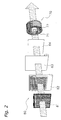
- the air cleaner 40 comprises a casing 60, a ventilation mechanism 70 (refer to FIG. 2), a control unit 50 (refer to FIG. 4), and a filter unit 80 (refer to FIG. 2).
- the casing 60 constitutes the outer surface of the air cleaner 40, and contains the ventilation mechanism 70, the control unit 50, and the filter unit 80.
- the casing 60 comprises a main body part 61 and a front panel 62.
- the main body part 61 comprises an upper surface suction port 63, side surface suction ports 64, and a blow out port 65.
- the upper surface suction port 63 and the side surface suction ports 64 are substantially rectangular openings that suction the indoor air into the air cleaner 40 in order to purify the indoor air therein.
- the upper surface suction port 63 is provided to the front surface side end part of the upper surface of the main body part 61, which is the same surface to which the blow out port 65 is provided.
- the side surface suction ports 64 are a pair of openings, wherein one is provided to the left side surface and the other is provided to the right side surface of the main body part 61.
- the blow out port 65 is provided on the rear surface side end part of the upper surface of the main body part 61.
- the blow out port 65 is an opening for blowing out the air from the air cleaner 40 to the indoor space after that air has been purified.
- the front panel 62 is provided on the front side of the main body part 61, and covers the filter unit 80 that is installed inside the main body part 61.
- the front panel 62 comprises a front surface suction port 66 and a display panel opening 67.
- the front surface suction port 66 is a substantially rectangular opening that is provided at substantially the center part of the front panel 62 and suctions the indoor air into the air cleaner 40.
- the display panel opening 67 is provided so that a display panel 56, which is discussed later, is visible from outside of the casing 60.
- the ventilation mechanism 70 sucks in the indoor air via the suction ports (the upper surface suction port 63, the side surface suction ports 64, and the front surface suction port 66), and blows out air from the blow out port 65 after it has been purified.
- the ventilation mechanism 70 is provided on the inner side of the casing 60, and is constituted so that the indoor air that is suctioned in from the suction ports 63, 64, 66 passes through the filter unit 80.
- the ventilation mechanism 70 comprises a fan motor 71 and a ventilation fan 72.
- the ventilation fan 72 is rotationally driven by the fan motor 71.
- An inverter motor which is frequency controlled by an inverter circuit, is used as the fan motor 71.
- a centrifugal fan is used as the ventilation fan 72.
- the air cleaner 40 further comprises the control unit 50, which comprises a microprocessor. As shown in FIG. 4, ROM 51, which stores, for example, a control program and various parameters, and RAM 52, which temporarily stores, for example, variables during processing, are connected to the control unit 50.
- ROM 51 which stores, for example, a control program and various parameters
- RAM 52 which temporarily stores, for example, variables during processing, are connected to the control unit 50.
- various sensors such as a temperature sensor 53, a humidity sensor 54, and a dust sensor 55, are connected to the control unit 50, into which the detection signals from each sensor are inputted.
- the dust sensor 55 can measure the particle concentration of, for example, dust by irradiating the introduced air with light, which is scattered by smoke, dust, pollen, and other particles contained in the air, and detecting the amount of light that reaches a light receiving device.
- the display panel 56 is connected to the control unit 50.
- the display panel 56 is constituted so that, for example, an operation mode, monitor information from various sensors, timer information, and maintenance information are displayed, and so that the operator can externally view such information via the display panel opening 67.
- control unit 50 is connected to the fan motor 71, and can control the operation of these devices in accordance with, for example, the operation of the user and the detection result of the various sensors.
- the filter unit 80 which is provided inside the casing 60, eliminates fine particles contained in the indoor air that is suctioned in via the suction ports 63, 64, 66.
- the filter unit 80 comprises a prefilter 81, an electrical discharge part 82, a photocatalytic filter 83, and a plasma catalytic filter 84.
- the filter unit 80 is constituted so that the indoor air that is suctioned in via the suction ports 63, 64, 66 passes through the interior of the filter unit 80, sequentially from the prefilter 81 to the electrical discharge part 82, the photocatalytic filter 83, and the plasma catalytic filter 84.
- the prefilter 81 eliminates, for example, comparatively large particles of dust from the air that is suctioned into the casing 60 by the ventilation mechanism 70.
- the prefilter 81 comprises a net part 810 and a frame 811 (refer to FIG. 5).
- the net part 810 which is a filamentous resin net made of polypropylene (hereinafter, referred to as PP), whereto, for example, comparatively large particles of dust contained in the air suctioned into the casing 60 adhere.
- the fiber that constitutes the net part 810 comprises a core 810a, which is made of PP, and an enveloping layer 814, which is made of the same PP.
- a visible light ray type photocatalyst 812 and a catechin 813 are supported on the enveloping layer 814 so that they are exposed to the air side.
- the visible light ray type photocatalyst 812 includes, for example, titanium oxide, wherein photocatalysis is activated by visible light, and eliminates viruses and bacteria, such as fungi and microbes contained in, for example, the dust that adheres to the net part 810.
- Catechin is one type of polyphenol and is a generic name for, for example, epicatechin, epigallocatechin, epicatechin gallate, and epigallocatechin gallate. Catechin deactivates viruses and suppresses the fertility of bacteria, such as fungi and microbes contained in, for example, the dust that adheres to the net part 810.
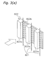
- the electrical discharge part 82 principally comprises an opposing electrode 822, ionization wires 821, and a streamer discharge electrode 823.
- the opposing electrode 822 is a metal plate that has a square wave shaped cross section, and comprises real electrode parts 822a, which function substantially as an electrode, and a plurality of slit parts 822b. Furthermore, the slit parts 822b serve to flow the air rearward.
- the ionization wires 821 are disposed on the airflow upstream side of the opposing electrode 822. Furthermore, at this point, one ionization wire 821 is disposed between each pair of adjacent real electrode parts 822a.
- each ionization wire 821 is formed from, for example, micro diameter tungsten wire, and is used as a discharge electrode.
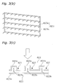
- the streamer discharge electrode 823 comprises electrode rods 823a and needle electrodes 823b. Each needle electrode 823b is fixed so that it is substantially orthogonal to its corresponding electrode rod 823a. Furthermore, as shown in FIG. 3(c), the streamer discharge electrode 823 is disposed on the airflow downstream side of the opposing electrode 822. Furthermore, at this point, the streamer discharge electrode 823 is disposed so that each needle electrode 823b opposes one of the real electrode parts 822a of the opposing electrode 822.
- the opposing electrode 822 and the ionization wires 821 of the electrodes 821, 822, 823 serve to charge the comparatively small particles of dust suspended in the air that passes through the prefilter 81.
- the opposing electrode 822 and the streamer discharge electrode 823 serve to generate activators, which are supplied to a photosemiconductor catalyst supporting filter 831 (discussed later). The following discusses combinations of these electrodes in detail.
- a discharge voltage of electricity that is, for example, direct current, alternating current, or pulsed is impressed between the streamer discharge electrode 823 and the opposing electrode 822 in the electrical discharge part 82, then a streamer discharge is generated between the electrodes 822, 823, as shown in FIG 3(d).
- a streamer discharge is generated, a low temperature plasma is produced in the electrical discharge field.
- this low temperature plasma generates high speed electrons, ions, ozone, and radicals, such as hydroxy radicals, as well as excited molecules (such as excited oxygen, nitrogen, and water molecules).
- these activators are carried along with the airflow and are supplied to the photosemiconductor catalyst supporting filter 831.
- these activators have extremely high energy levels and are capable of decomposing and deodorizing small organic molecules, such as ammonias, aldehydes, and nitrogen oxides contained in the air, even before they reach the photosemiconductor catalyst supporting filter 831.
- FIG 7 shows a partial cross sectional view of the photocatalytic filter 83.
- the photocatalytic filter 83 is a roll around which a length of filter material, in the amount of several uses worth, is wound, and is constituted so that if the surface in use becomes dirty, then the photocatalytic filter 83 can be pulled and the dirtied portion can then be cut off.
- the photocatalytic filter 83 is formed so that the electrostatic filter 830 and the photosemiconductor catalyst supporting filter 831 are laminated together. Furthermore, the photocatalytic filter 83 is disposed so that the electrostatic filter 830 faces the upstream side of the airflow produced by the ventilation mechanism 70 and so that the photosemiconductor catalyst supporting filter 831 faces the downstream side of the airflow.
- the dust and the like that were electrically charged by the electrical discharge part 82 are adsorbed to the electrostatic filter 830.
- the dust and the like that pass through the electrostatic filter 830 are adsorbed to the photosemiconductor catalyst supporting filter 831.
- the airflow downstream side surface of the photosemiconductor catalyst supporting filter 831 is coated with a mixture of titanium dioxide particles of the anatase form and titanium apatite particles.
- the titanium dioxide particles are 0.1 to 1.0 ⁇ m in diameter
- the titanium apatite particles are 1 to 10 ⁇ m in diameter.
- the mixture ratio by weight of the titanium dioxide and the titanium apatite is 100:20.
- the titanium apatite is an apatite wherein some of the calcium atoms of calcium hydroxyapatite are substituted with titanium atoms by a technique such as ion exchange.
- the plasma catalytic filter 84 is formed from PP fibers 844, upon which a mixture 847 of titanium dioxide particles 846 of the anatase form and titanium apatite particles 845 is supported. Furthermore, similar to the prefilter 81, each fiber 844 comprises a core 842 and an enveloping layer 843, and the mixture 847 is supported on the enveloping layer 843.
- the titanium dioxide particles 846 are 0.1 to 1.0 ⁇ m in diameter
- the titanium apatite particles 845 are 1 to 10 ⁇ m in diameter.
- the mixture ratio by weight of the titanium dioxide and the titanium apatite is 100:20.
- the plasma catalytic filter 84 adsorbs, for example, viruses and bacteria in the air that were not adsorbed to the photocatalytic filter 83.
- the titanium dioxide which is activated by the activators, destroys or inactivates, for example, the adsorbed bacteria and viruses.
- FIG 10 shows a melt spinning apparatus 90 for manufacturing the fibers that form the filters 81, 83, 84.
- the melt spinning apparatus 90 principally comprises a first drying apparatus 91a, a second drying apparatus 91b, a first discharge apparatus 92a, a second discharge apparatus 92b, a discharge nozzle 93, a cooling apparatus 94, a payout apparatus 95, a drawing apparatus 96, a tunnel heater 97, a heat treatment apparatus 98, and a take-up apparatus 99.
- Pellets of polypropylene resin that has a high melting point are supplied to the first drying apparatus 91a. Furthermore, those pellets are heated and dried at the first drying apparatus 91a until their moisture percentage content is below a predetermined value. Meanwhile, pellets of polypropylene resin, wherein the mixture 847 of the titanium dioxide particles 846 of the anatase form and the titanium apatite particles 845 (refer to FIG 9) is dispersed in advance, that has a low melting point are supplied to the second drying apparatus 91b. Furthermore, these pellets are heated and dried at the second drying apparatus 91b until their moisture percentage content is below a predetermined value.
- the pellets that have been sufficiently dried in the first drying apparatus 91a are supplied to the first discharge apparatus 92a.
- the first discharge apparatus 92a principally comprises a heater (not shown), a screw 921, and a cylinder 922.
- the heater melts the pellets and the screw 921 moves the melted polypropylene (hereinbelow, referred to as molten PP) inside the cylinder 922 toward the discharge nozzle 93 side.
- the pellets that have been sufficiently dried in the second drying apparatus 91 bare supplied to the second discharge apparatus 92b.
- the second discharge apparatus 92b principally comprises a heater (not shown), a screw 921, and a cylinder 922.
- the heater melts the pellets and the screw 921 moves the melted mixture-containing polypropylene (hereinbelow, referred to as MX-containing molten PP) inside the cylinder 922 toward the discharge nozzle 93 side.
- MX-containing molten PP melted mixture-containing polypropylene
- the molten PP and the MX-containing molten PP which are supplied from the first discharge apparatus 92a and the second discharge apparatus 92b, are supplied to the discharge nozzle 93.
- the discharge nozzle 93 has a side sectional structure as shown in FIG. 11 (a) and a discharge port that is shaped as shown in FIG 11 (b).
- the molten PP flows through a first pathway (refer to the solid line arrow in FIG. 11(a)).
- the MX-containing molten PP flows through a second pathway (refer to the broken arrows in FIG 11 (a)).
- the molten PP and the MX-containing molten PP are discharged from the discharge nozzle 93, integrated in a form so that the MX-containing molten PP covers the molten PP (hereinafter, the integrated molten PP and MX-containing molten PP is referred to as the composite melt), and then sent to the cooling apparatus 94.
- the cooling apparatus 94 uses a coolant to cool and harden the composite melt, thereby forming a fiber (hereinafter, a fiber so formed is referred to as a composite fiber). Furthermore, the composite fiber is sent to the payout apparatus 95 via a dip roller 94a and a discharge roller 94b, which are disposed inside a tank of coolant.
- the payout apparatus 95 which comprises payout rollers 95a, pays out the composite fiber to the tunnel heater 97 at a fixed speed.
- the drawing apparatus 96 which comprises drawing rollers 96a, pulls the composite fiber, which exits from the tunnel heater 97, at a speed greater than the speed at which it is paid out from the payout apparatus 95. As a result, the composite fiber is heated and drawn between the payout apparatus 95 and the drawing apparatus 96.
- a thin-film outer layer (the layer of the polypropylene resin that contains the mixture) of the composite fiber forms, and some of the encapsulated titanium dioxide particles 846 and titanium apatite particles 845 are exposed to the surface of that outer layer (hereinbelow, the fibers in this state are referred to as the photosemiconductor catalyst exposed fibers 844 (refer to FIG. 9)).
- the photosemiconductor catalyst exposed fibers 844 are subsequently guided to the heat treatment apparatus 98.
- the heat treatment apparatus 98 has a heater (not shown) that heats so that the interior of the heat treatment apparatus 98 reaches a prescribed temperature.
- the photosemiconductor catalyst exposed fibers 844 are heat treated while being moved along guide rollers 98a. This heat treatment proceeds to crystallize the core 842 of each photosemiconductor catalyst exposed fiber 844, the strength of the fiber 844 is maintained at a predetermined value or greater. Furthermore, the photosemiconductor catalyst exposed fibers 844 that exit from the heat treatment apparatus 98 are wound up by a take-up roller 99a of the take-up apparatus 99.
- the photosemiconductor catalyst exposed fibers 844 manufactured by the process described above exhibit a shape as shown in FIG 9.
- the filters 81, 83, 84 are manufactured as nonwoven fabric by thermal fusing the photosemiconductor catalyst exposed fibers 844 without weaving them.
- the airflow downstream side surface of the photosemiconductor catalyst supporting filter 831 is coated with a mixture of titanium dioxide particles of the anatase form, wherein the secondary particles are 0.1 to 1.0 ⁇ m in diameter, and titanium apatite particles, wherein the secondary particles are 1 to 10 ⁇ m in diameter.
- the small-sized secondary particles of the titanium dioxide enter the gaps between the large-sized secondary particles of the titanium apatite, thereby creating active sites for photocatalytic reaction similar to those of conventional titanium dioxide.
- the titanium apatite specifically adsorbs bacteria and viruses.
- this photocatalytic filter 83 is capable of exhibiting cleaning capacity that is superior to that of a photocatalytic filter coated with a conventional photosemiconductor catalyst.
- the PP fibers 844 of the plasma catalytic filter 84 support the mixture 847 of the titanium dioxide particles 846 of the anatase form, wherein the secondary particles are 0.1 to 1.0 ⁇ m in diameter, and the titanium apatite particles 845, wherein the secondary particles are 1 to 10 ⁇ m in diameter.
- the small-sized secondary particles of the titanium dioxide enter the gaps between the large-sized secondary particles of the titanium apatite, thereby creating active sites for photocatalytic reaction similar to those of conventional titanium dioxide.
- the titanium apatite specifically adsorbs bacteria and viruses.
- these fibers 844 are capable of exhibiting cleaning capacity that is superior to that of fibers whereon a conventional photosemiconductor catalyst is supported.
- each of the fibers 844 that constitute the plasma catalytic filter 84 comprises the core 842 and the enveloping layer 843, and the titanium dioxide particles 846 of the anatase form as well as the titanium apatite particles 845 are supported on the enveloping layer 843 so that they are exposed to the air side.
- a resin is filled with, for example, particle filler, that resin has a strong tendency to embrittle.
- each of the fibers 844 has a core 842, there is virtually no such risk.
- by exposing the titanium dioxide particles 846 and the titanium apatite particles 845 to the air side they exhibit sufficient photocatalytic functioning.
- the mixture ratio by weight of titanium dioxide particles of the anatase form, wherein the secondary particles are 0.1 to 1.0 ⁇ m in diameter, and titanium apatite particles, wherein the secondary particles are 1 to 10 ⁇ m in diameter is 100:20, and this mixture is coated or supported on the filters 83, 84.
- FIG 13 shows a graph that illustrates the oxidative decomposition efficiency of titanium dioxide and titanium apatite with respect to acetaldehyde for the case wherein the titanium dioxide particles 846 of the anatase form, wherein the secondary particles are 0.1 to 1.0 ⁇ m in diameter, and the titanium apatite particles 845, wherein the secondary particles are 1 to 10 ⁇ m in diameter, are of the same weight.
- the titanium oxide and the titanium apatite are not irradiated with ultraviolet light until ten minutes from the measurement start time have elapsed, and are irradiated thereafter.
- the titanium dioxide oxidatively decomposes the acetaldehyde so that its concentration decreases by about 15 ppm approximately three minutes from the start of ultraviolet light irradiation; in contrast, after the elapse of as much as 20 minutes from the start of ultraviolet light irradiation, the titanium apatite gradually oxidatively decomposes the acetaldehyde so that its concentration decreases by approximately 24 ppm. Accordingly, the speed at which the titanium dioxide oxidatively decomposes the acetaldehyde is approximately 5.0 ppm/min.
- the speed at which the titanium apatite oxidatively decomposes the acetaldehyde is approximately 1.2 ppm/min. Accordingly, the oxidative decomposition speed ratio of the titanium dioxide and the titanium apatite with respect to the acetaldehyde is approximately 1:0.24.
- these filters 83, 84 can exhibit a cleaning capacity that is superior to a filter whereon the titanium dioxide is supported as is.
- the photocatalytic function of the titanium apatite is activated by activators, but the photocatalytic function of, for example, titanium apatite or titanium dioxide may instead be activated by using, for example, an ultraviolet light lamp.
- fibers 844 are used, each of which has a core 842, as the fibers that constitute the plasma catalytic filter 84, but fibers may be used wherein the titanium dioxide particles 846 and the titanium apatite particles 845 are substantially uniformly dispersed internally as well, as shown in FIG 14. Note that some of the titanium dioxide particles 846 and the titanium apatite particles 845 are exposed to the fiber surface.
- the present invention is adapted to the air cleaner 40, but may be adapted to an air conditioner 200 that performs cooling and heating, as shown in FIG 15.
- the air conditioner 200 is a device for supplying conditioned air to an indoor space, and comprises an indoor unit 201, which is affixed to, for example, a wall surface of the indoor space, and an outdoor unit 202, which is installed in the outdoor space.
- a suction port 205 for taking the air of the indoor space into the air conditioner 200 is provided to the indoor unit 201, and the inner side of this suction port 205 is equipped with a filter unit (not shown). Also in the case wherein the present invention is adapted to this filter unit, viruses, fungi, microbes, and the like adhering and adsorbed to the filter unit are eliminated, which consequently suppresses the occurrence of, for example, offensive odor and air pollution.
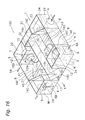
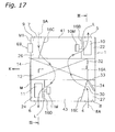
- FIGS. 16, 17, 18, and 19 show an oblique view, a top view, a side view, and an exploded oblique view, respectively, of the internal structure of a total heat exchanging unit according to one embodiment of the present invention.
- a total heat exchanging unit 100 is an apparatus for ventilating an indoor space while exchanging heat between supply air SA (solid line outline arrow) from an outdoor space and exhaust air EA (hatched outline arrow) from the indoor space via a heat exchange element 12.
- SA solid line outline arrow
- EA hatchched outline arrow
- the present total heat exchanging unit 100 principally comprises a casing 1, a heat exchange element 12, air filters 12b, fans 10, 11, a damper 34, and an electrical equipment box EB.
- the casing 1 comprises a casing body 2 and a cover body 3, which covers the upper surface of the casing body 2. Furthermore, a heat exchange element chamber 21, an exhaust air fan motor housing chamber 41, an exhaust air fan housing chamber 22, a supply air fan motor housing chamber 43, a supply air fan housing chamber 24, a supply air communicating chamber 45, an exhaust air communicating chamber 46, an outdoor side suction chamber 26, an indoor side suction chamber 27, and a bypass chamber 31 are provided in the casing 1.
- a heat exchange element chamber 21 an exhaust air fan motor housing chamber 41, an exhaust air fan housing chamber 22, a supply air fan motor housing chamber 43, a supply air fan housing chamber 24, a supply air communicating chamber 45, an exhaust air communicating chamber 46, an outdoor side suction chamber 26, an indoor side suction chamber 27, and a bypass chamber 31 are provided in the casing 1.
- a heat exchange element chamber 21 an exhaust air fan motor housing chamber 41, an exhaust air fan housing chamber 22, a supply air fan motor housing chamber 43, a supply air fan housing chamber 24, a supply air communicating chamber 45, an exhaust air communicating chamber
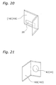
- the heat exchange element chamber 21 is a rectangular parallelepipedic space, as shown in FIG. 16 and FIG 18, and houses the heat exchange element 12. Furthermore, the heat exchange element chamber 21 is formed so that it is partitioned by, for example, a bottom plate of the casing body 2, partition plates 16A-16E (refer to FIGS. 16, 20, and 21), and the cover body 3.
- guide parts G1, G2, G3 are affixed to the bottom plate of the casing body 2, the partition plates 16A-16E, and the cover body 3, respectively.
- the guide part G1, which is affixed to the bottom plate of the casing body 2 comprises a first guide part G11 and second guide parts G12.
- the first guide part G11 guides the ridgeline of the lower part of the heat exchange element 12 when the heat exchange element 12 is inserted or removed.
- a pair of second guide parts G12 is disposed so that the first guide part G11 is interposed therebetween, and guides the end edges of the pair of air filters 12b.
- the guide part G2, which is affixed to the partition plates 16A-16E, comprises a first guide part G21 and a second guide part G22.
- the first guide part G21 guides a ridgeline of a side part of the heat exchange element 12 when the heat exchange element 12 is inserted or removed.
- the second guide part G22 guides the end edges of the air filters 12b.
- the guide part G3, which is affixed to the cover body 3, guides a ridgeline of an upper part of the heat exchange element 12 when the heat exchange element 12 is inserted or removed.
- housing the heat exchange element 12 in the heat exchange element chamber 21 creates four substantially triangular prism shaped spaces 17, 18, 19, 20 therein.
- the spaces indicated by reference symbols 17, 18, 19, and 20 in FIG 16 and FIG. 18 are called a first space, a second space, a third space, and a fourth space, respectively.
- the exhaust air fan housing chamber 22 houses the exhaust air fan 10, as shown in FIG 16 and FIG 19.
- the exhaust air fan housing chamber 22 communicates with the exhaust air fan motor housing chamber 41 via an opening 42, which is formed in the partition plate 16B.
- the exhaust air fan housing chamber 22 comprises an exhaust air outdoor side blow out port 7 on its side wall.
- the exhaust air fan motor housing chamber 41 houses an exhaust air fan motor 10M, as shown in FIG. 16 and FIG. 19. In addition, the exhaust air fan motor housing chamber 41 communicates with the first space 17 via an opening 23, which is partitioned by the cover body 3 and one of the ridgelines of the heat exchange element 12, as shown in FIG. 16.
- the supply air fan housing chamber 24 houses the supply air fan 11, as shown in FIG. 16 and FIG. 19.
- the supply air fan housing chamber 24 communicates with the supply air fan motor housing chamber 43 via an opening 44, which is formed in the partition plate 16D, as shown in FIG 16.
- the supply air fan housing chamber 24 comprises a supply air indoor side blow out port 6 on its side wall, as shown in FIG. 16.
- the supply air fan motor housing chamber 43 houses a supply air fan motor 11M, as shown in FIG. 16 and FIG. 19. In addition, the supply air fan motor housing chamber 43 communicates with the second space 18 via an opening 25, which is partitioned by the cover body 3 and one of the ridgelines of the heat exchange element 12.
- the outdoor side suction chamber 26 comprises a supply air outdoor side suction port 5 on its side wall, as shown in FIG. 16.
- the outdoor side suction chamber 26 communicates with the supply air communicating chamber 45 via an opening 29 of the partition plate 16C, as shown in FIG 16 and FIG 20.
- the indoor side suction chamber 27 comprises an exhaust air indoor side suction port 4 on its side wall, as shown in FIG. 16.
- the indoor side suction chamber 27 communicates with the exhaust air communicating chamber 46 via an opening 30 of the partition plate 16E, as shown in FIG. 16.
- the supply air communicating chamber 45 is partitioned by the partition plate 16F, and is positioned below the exhaust air fan motor housing chamber 41. In addition, the supply air communicating chamber 45 communicates with the third space 19, as shown in FIG. 16.
- the exhaust air communicating chamber 46 is partitioned by the partition plate 16G, and is positioned below the supply air fan motor housing chamber 43. In addition, the exhaust air communicating chamber 46 communicates with the fourth space 20, as shown in FIG. 16.
- the bypass chamber 31 is positioned on the side opposite an extraction direction K of the heat exchange element chamber 21. Furthermore, the bypass chamber 31 communicates with the first space 17 via an opening 32. In addition, the bypass chamber 31 communicates with the indoor side suction chamber 27 via an opening 33. As a result, the exhaust air fan housing chamber 22 and the indoor side suction chamber 27 communicate via the exhaust air fan motor housing chamber 41, the first space 17, and the bypass chamber 31.
- the heat exchange element 12 is formed substantially as a rectangular parallelepiped, as shown in FIG. 16 and FIG. 19, and is provided to the intersecting portion between an exhaust air passageway 8 and a supply air passageway 9.
- the heat exchange element 12 has a laminar structure, wherein special pleated kraft paper (hereinbelow, referred to as spacer paper) 122 and special flat sheet shaped kraft paper (hereinbelow, referred to as partitioning paper) 121 are stacked in alternating directions, as shown in FIG. 22. Because the heat exchange element 12 is so structured, passageways in the heat exchange element 12 for the exhaust air EA and the supply air SA are disposed so that they alternate by level.
- the sensible heat and the latent heat of the supply air SA and the exhaust air EA are exchanged via the partitioning paper 121.
- the spacer paper 122 and the partitioning paper 121 are coated with a mixture of titanium dioxide particles of an anatase form and titanium apatite particles, the same as the photocatalytic filter of the first embodiment.
- a handle 12a for removing the heat exchange element 12 is provided to an end surface of the heat exchange element 12, which can be inserted or removed in the longitudinal direction along its long side via an insertion/removal opening 13, which is open to a maintenance surface M of the casing 1, by removing a cover 14 as shown in FIG. 19.
- the air filters 12b are affixed to the heat exchange element 12 so that they cover the surfaces of the heat exchange element 12 that contact the third space 19 and the fourth space 20.
- Each of the air filters 12b is a nonwoven fabric that is made of polytetrafluoroethylene fibers. Furthermore, the air filters 12b principally catch comparatively large particles of dust, and cannot capture fine bioparticles, such as bacteria, viruses and the like.
- a streamer discharger 15 is provided in the third space 19 and another is provided in the fourth space 20, and each one activates the photocatalytic function of the titanium apatite, which is supported inside the heat exchange element 12, by supplying activators, such as high speed electrons, ions, ozone, and radicals like hydroxy radicals, as well as other excited molecules (such as excited oxygen, nitrogen, and water molecules), to the inside of the heat exchange element 12.
- activators such as high speed electrons, ions, ozone, and radicals like hydroxy radicals, as well as other excited molecules (such as excited oxygen, nitrogen, and water molecules).
- Each of the streamer dischargers 15 comprises a discharge electrode 15a and an opposing electrode 15b.
- the discharge electrode 15a comprises an electrode rod 151 and a plurality of needle electrodes 152, as shown in FIG. 23. Furthermore, the needle electrodes 152 are fixed so that they are substantially orthogonal to the electrode rod 151.
- the opposing electrode 15b is a plate shaped electrode and comprises a plurality of openings, wherethrough air passes in the surface normal direction. Furthermore, the electrode rod 151 of the discharge electrode 15a and the opposing electrode 15b are disposed substantially parallel to one another. As a result, each of the needle electrodes 152 of the discharge electrode 15a forms a substantially right angle with the opposing electrode 15b.
- the discharge electrode 15a and the opposing electrode 15b are connected to a high voltage power supply (not shown) that supplies direct current, alternating current, or pulsed electricity. Furthermore, if an electrical discharge voltage is impressed upon the discharge electrode 15a and the opposing electrode 15b, a streamer discharge is generated between the needle electrodes 152 of the discharge electrode 15a and the opposing electrode 15b.
- low temperature plasma is generated in the electrical discharge field when the streamer discharge occurs. Furthermore, this low temperature plasma generates high speed electrons, ions, ozone, and radicals, such as hydroxy radicals, as well as other excited molecules (such as excited oxygen, nitrogen, and water molecules). Furthermore, these activators are carried along with the airflow, pass through the openings of the opposing electrode 15b, and are supplied to the heat exchange element 12.
- the streamer discharger 15 is energized only in a heat exchange element cleaning mode, which is discussed later.
- the exhaust air fan 10 and the supply air fan 11 are sirocco fans (rotors), as shown in FIG 17 and FIG. 18, and are housed inside a curled fan casing (not shown) that is made of a resin foam (e.g., expanded polystyrene). Furthermore, a rotational axis line L of each of the fans 10, 11 is parallel to the extraction direction K of the heat exchange element 12.
- the damper 34 is disposed inside the indoor side suction chamber 27.
- the damper 34 is pivoted by, for example, an electric motor (not shown) that opens either the opening 30 or the opening 33 and blocks the other.
- the electrical equipment box EB is disposed in a portion M1, which opposes the exhaust air fan 10, of the maintenance surface M.
- the electrical equipment box EB houses electrical equipment, such as a control circuit board (not shown). Furthermore, the control circuit board is connected to and in communication with a wired remote control (not shown), and controls the operation of the fans 10, 11 and the damper 34 based on signals sent from the wired remote control.
- the total heat exchanging unit 100 is provided with three operation modes, i.e., a total heat exchange ventilation mode, a normal ventilation mode, and the heat exchange element cleaning mode. The following describes the details of each of these operation modes.
- the damper 34 opens the opening 30. Furthermore, as discussed above, the opening 33 is blocked at this time. Furthermore, if the fans 10, 11 are operated in this state, the indoor air is suctioned via a duct from the indoor side suction port 4 into the indoor side suction chamber 27, passes through the exhaust air passageway 8, which extends from the opening 30 to the exhaust air communicating chamber 46, the fourth space 20, the air filters 12b, the heat exchange element 12, the first space 17, the opening 23, the exhaust air fan motor housing chamber 41, and the exhaust air fan housing chamber 22, and is then blown out from the outdoor side blow out port 7 and exhausted to the outdoor space via a duct; simultaneously, the outdoor air is suctioned via a duct from the outdoor side suction port 5 into the outdoor side suction chamber 26, passes through the supply air passageway 9, which extends from the supply air communicating chamber 45 to the third space 19, the air filters 12b, the heat exchange element 12, the second space 18, the opening 25, the supply air fan
- Normal ventilation which does not perform heat exchange, is performed during intermediate seasons, such as spring and fall, when cooling and heating are not needed.
- the damper 34 opens the opening 33. Furthermore, as discussed above, the opening 30 is blocked at this time. Furthermore, if the fans 10, 11 are operated in this state, the indoor air is suctioned via a duct from the indoor side suction port 4 into the indoor side suction chamber 27, passes through a bypass ventilation passageway, which extends from the opening 33 to the bypass chamber 31, the opening 32, the first space 17, the opening 23, exhaust air fan motor housing chamber 41, and the exhaust air fan housing chamber 22, and is then blown out from the outdoor side blow out port 7 and exhausted via a duct to the outdoor space; simultaneously, the outdoor air is suctioned via a duct from the outdoor side suction port 5 into the outdoor side suction chamber 26, passes through the supply air passageway 9, which extends from the supply air communicating chamber 45 to the third space 19, the air filters 12b, the heat exchange element 12, the second space 18, the opening 25, the supply air fan motor housing chamber 43, the opening 44, and the supply air fan housing chamber 24, and is then blown out from
- control is performed so that the rotational speed of the fans 10, 11 reaches a state wherein the amount of ventilation is minimized as much as possible; simultaneously, the streamer dischargers 15 are energized.
- the heat exchange element 12 is coated with a mixture of titanium dioxide particles of the anatase form, wherein the secondary particles are 0.1 to 1.0 ⁇ m in diameter, and titanium apatite, wherein the secondary particles are 1 to 10 ⁇ m in diameter.
- the small-sized secondary particles of the titanium dioxide enter the gaps between the large-sized secondary particles of the titanium apatite. Accordingly, active sites for photocatalytic reaction can be created that are similar to those of conventional titanium dioxide.
- the titanium apatite specifically adsorbs bacteria and viruses.
- the total heat exchanging unit 100 can exhibit cleaning capacity that is superior to that of a total heat exchanging unit that uses a conventional photosemiconductor catalyst.
- the heat exchange element 12 is coated with a mixture of titanium dioxide particles of the anatase form, wherein the secondary particles are 0.1 to 1.0 ⁇ m in diameter, and titanium apatite, wherein the secondary particles are 1 to 10 ⁇ m in diameter; however, in addition thereto, the same mixture may be coated on one or both sides of the air filters.
- a cleaning treatment material according to the present invention can exhibit cleaning capacity superior to that of a conventional photosemiconductor catalyst, and can be adapted to cleaning related technologies, such as those that use air or water.
Landscapes
- Chemical & Material Sciences (AREA)
- Engineering & Computer Science (AREA)
- Chemical Kinetics & Catalysis (AREA)
- Materials Engineering (AREA)
- Organic Chemistry (AREA)
- Combustion & Propulsion (AREA)
- General Engineering & Computer Science (AREA)
- Mechanical Engineering (AREA)
- General Chemical & Material Sciences (AREA)
- Environmental & Geological Engineering (AREA)
- Analytical Chemistry (AREA)
- Biomedical Technology (AREA)
- Health & Medical Sciences (AREA)
- Oil, Petroleum & Natural Gas (AREA)
- Disinfection, Sterilisation Or Deodorisation Of Air (AREA)
- Catalysts (AREA)
- Exhaust Gas Treatment By Means Of Catalyst (AREA)
- Filtering Materials (AREA)
- Air Filters, Heat-Exchange Apparatuses, And Housings Of Air-Conditioning Units (AREA)
Abstract
It is an object of the present invention to provide a cleaning treatment material that exhibits cleaning capacity superior to that of a conventional photosemiconductor catalyst in a case wherein the weight of the cleaning treatment material that can support an air cleaning member is limited to a certain extent. The cleaning treatment material (847) is a mixture of a photosemiconductor catalyst (846) and an apatite (845), which has a photocatalytic function. Furthermore, the secondary particles of the photosemiconductor catalyst (846) are 0.1 to 1.0 µm in diameter. In addition, the secondary particles of the apatite (845) are 1 to 10 µm in diameter.
Description
- The present invention relates to a cleaning treatment material, an air filter, an air conditioner, a heat exchange element, and a heat exchanging unit.
- Conventional examples of catalysts that can be cited as photosemiconductor catalysts include: metal oxides, as represented by, for example, titanium oxide, strontium titanate, zinc oxide, tungsten oxide, and iron oxide; carbonaceous photocatalysts, as represented by fullerenes, such as C60; as well as nitrides and oxynitrides consisting of transition metals. If such a photosemiconductor catalyst is irradiated by light (for example, ultraviolet light) that has an energy greater than its band gap, then the electrons in the valence band are excited to the conduction band, and positive holes generate in the valence band, and electrons generate in the conductor. As a result, the oxidation reaction easily occurs on the valence band side, and a reduction reaction easily occurs on the conductor side. Furthermore, in this state, if air, water, and the like contact the surface of the photosemiconductor catalyst, then they cause a chemical reaction that generates active oxygen, such as OH-, O2, O2-, and H2O2. In turn, the active oxygen decomposes the various organic substances present in the vicinity of the photosemiconductor catalyst.
- Incidentally, there is a problem in that the speed of the cleaning process is insufficient in certain fields because the ability of these photosemiconductor catalysts to actively adsorb the organic substances is inferior. To eliminate this problem, work is currently in progress to develop a catalyst with a photocatalytic function (hereinbelow, referred to as photocatalytic apatite) that strongly adsorbs organic substances by substituting some atoms of an apatite with other atoms (e.g., refer to
Patent Document 1 and Patent Document 2); and, actually, the adsorption performance is improved. -
Japanese Published Unexamined Patent Application No. 2004-2176 -
Japanese Published Unexamined Patent Application No. 2001-302220 - With present day particle size control technology, it is extremely difficult to make the specific surface area (surface area per unit weight) of a photosemiconductor catalyst apatite larger than that of a conventional photosemiconductor catalyst. Accordingly, if the speed of the cleaning process for a conventional photosemiconductor catalyst is compared with that for a photosemiconductor catalyst apatite of the same weight, then the latter is inferior to the former.
- It is an object of the present invention to provide a cleaning treatment material that exhibits cleaning capacity that is superior to that of a conventional photosemiconductor catalyst.
- A cleaning treatment material according to a first aspect of the invention is a mixture of a photosemiconductor catalyst and an apatite that has a photocatalytic function. Furthermore, the secondary particles of the photosemiconductor catalyst are 0.1 to 1.0 µm in diameter. In addition, the secondary particles of the apatite that has a photocatalytic function are 1 to 10 µm in diameter. Furthermore, the "photosemiconductor catalyst" herein includes: metal oxides, as represented by, for example, titanium oxide, strontium titanate, zinc oxide, tungsten oxide, and iron oxide; carbonaceous photosemiconductor catalysts, as represented by fullerenes, such as C60; nitrides and oxynitrides consisting of transition metals; and apatites that have a photocatalytic function. In addition, "apatites that have a photocatalytic function" herein are apatites wherein, for example, some of the calcium atoms of a calcium hydroxyapatite are substituted with titanium atoms using a technique such as ion exchange.
- In this aspect of the invention, the cleaning treatment material is a mixture of the photosemiconductor catalyst and the apatite that has a photocatalytic function. Consequently, the small-sized secondary particles of the photosemiconductor catalyst enter the gaps between the large-sized secondary particles of the apatite that has a photocatalytic function. Accordingly, it is possible to create active sites for photocatalytic reaction similar to those of a conventional photosemiconductor catalyst. In addition, in this state, the apatite, which has a photocatalytic function, specifically adsorbs, for example, bacteria and viruses. As a result, the cleaning treatment material can exhibit cleaning capacity superior to that of a conventional photosemiconductor catalyst.
- A cleaning treatment material according to a second aspect of the invention is a cleaning treatment material according to the first aspect of the invention, wherein 10-35 parts by weight of the apatite, which has a photocatalytic function, are mixed with 100 parts by weight of the photosemiconductor catalyst. In addition, the apatite, which has a photocatalytic function, is more preferably 15-35 parts by weight.
- It was confirmed that the oxidative decomposition speed of the acetaldehyde by the photosemiconductor catalyst, which is 100 parts by weight and has secondary particles that are 0.1 to 1.0 µm in diameter, is approximately four times the oxidative decomposition speed of the acetaldehyde by the apatite that has a photocatalytic function, which is 100 parts by weight and has secondary particles that are 1 to 10 µm in diameter.
- In this aspect of the invention, 10-35 parts by weight of the apatite that has a photocatalytic function, wherein secondary particles are 1 to 10 µm in diameter, are mixed with 100 parts by weight of the photosemiconductor catalyst, wherein the secondary particles are 0.1 to 1.0 µm in diameter, thereby producing the cleaning treatment material. This mixing ratio is derived from the oxidative decomposition speed ratio of the photosemiconductor catalyst to the apatite that has a photocatalytic function, and from the adsorption performance of the acetaldehyde by the apatite that has a photocatalytic function, and this mixing ratio yields a higher processing performance with respect to, for example, bacteria, viruses and the like, than the case wherein only the photosemiconductor catalyst is used. Accordingly, the cleaning treatment material exhibits a cleaning capacity superior to that of a conventional photosemiconductor catalyst.
- A cleaning treatment material according to a third aspect of the invention is a cleaning treatment material according to the first or second aspect of the invention, wherein the photosemiconductor catalyst is titanium dioxide.
- In this aspect of the invention, the photosemiconductor catalyst is titanium dioxide. The titanium dioxide has excellent cost performance among photosemiconductor catalysts. Consequently, the present invention can overcome the problems while suppressing cost increases.
- A cleaning treatment material according to a fourth aspect of the invention is a cleaning treatment material according to the first or second aspect of the invention, wherein the apatite, which has a photocatalytic function, is titanium apatite. Furthermore, the "titanium apatite" herein is an apatite wherein some of the calcium atoms of, for example, calcium hydroxyapatite are substituted with titanium atoms by a technique, such as ion exchange.
- In this aspect of the invention, the apatite that has a photocatalytic function is titanium apatite. The titanium apatite can be easily prepared from calcium hydroxyapatite using the ion exchange method, and is superior in that it has the best cost performance among apatites that have a photocatalytic function. Consequently, the present invention can overcome problems while suppressing cost increases.
- An air filter according to the fifth aspect of the invention supports the cleaning treatment material according to any one aspect of the first through fourth aspects of the invention.
- In this aspect of the invention, the air filter supports the cleaning treatment material according to any one aspect of the first through fourth aspects of the invention. Consequently, this air filter can exhibit a cleaning capacity superior to that of air filters that support a conventional photosemiconductor catalyst.
- An air conditioner according to sixth aspect of the invention comprises an air filter according to the fifth aspect of the invention.
- In this aspect of the invention, the air conditioner comprises an air filter according to the fifth aspect of the invention. Consequently, this air conditioner can exhibit a cleaning capacity superior to that of an air conditioner that uses a conventional photosemiconductor catalyst.
- A heat exchange element according to the seventh aspect of the invention supports a cleaning treatment material according to any one aspect of the first through fourth aspects of the invention.
- In this aspect of the invention, the heat exchange element supports a cleaning treatment material according to any one aspect of the first through fourth aspects of the invention. Consequently, this heat exchange element can exhibit a cleaning capacity superior to that of a heat exchange element that supports a conventional photosemiconductor catalyst.
- A heat exchanging unit according to the eighth aspect of the invention comprises a heat exchange element according to the seventh aspect of the invention.
- In this aspect of the invention, the heat exchanging unit comprises a heat exchange element according to the seventh aspect of the invention. Consequently, this heat exchanging unit can exhibit a cleaning capacity superior to that of a heat exchanging unit that uses a conventional photosemiconductor catalyst.
- The cleaning treatment material according to the first aspect of the invention can exhibit a cleaning capacity superior to that of a conventional photosemiconductor catalyst.
- The cleaning treatment material according to the second aspect of the invention can exhibit a cleaning capacity superior to that of a conventional photosemiconductor catalyst.
- The cleaning treatment material according to the third aspect of the invention can overcome the problems of the present invention while suppressing cost increases.
- The cleaning treatment material according to the fourth aspect of the invention can overcome the problems of the present invention while suppressing cost increases.
- The air filter according to the fifth aspect of the invention can exhibit a cleaning capacity superior to that of an air filter that supports a conventional photosemiconductor catalyst.
- The air conditioner according to the sixth aspect of the invention can exhibit a cleaning capacity superior to that of an air conditioner that uses a conventional photosemiconductor catalyst.
- The heat exchange element according to the seventh aspect of the invention can exhibit a cleaning capacity superior to that of a heat exchange element that supports a conventional photosemiconductor catalyst.
- The heat exchanging unit according to the eighth aspect of the invention can exhibit a cleaning capacity superior to that of a heat exchanging unit that uses a conventional photosemiconductor catalyst.
-
- FIG. 1 is an external oblique view of an air cleaner according to a first embodiment.
- FIG. 2 is an exploded oblique view of filters and a ventilation mechanism.
- FIG. 3(a) is an oblique view that shows the structure of an electrical discharge part on the airflow upstream side.
- FIG. 3(b) is an oblique view that shows the shape of a streamer discharge electrode.
- FIG. 3(c) is a top view layout drawing of the electrical discharge part.
- FIG. 3(d) shows an aspect of streamer discharge.
- FIG. 4 is a schematic block diagram of a control unit.
- FIG. 5 is a detail drawing of a prefilter.
- FIG 6 is a cross sectional enlarged view of a fiber that constitutes a net part of the prefilter.
- FIG 7 is a partial side sectional view of a roll filter.
- FIG 8 shows an air filter and fibers according to the present invention.
- FIG 9 is an enlarged view of the fiber according to the present invention.
- FIG 10 is a simplified view of an apparatus for manufacturing the fiber according to the present invention.
- FIG. 11(a) is a cross sectional view of a discharge part.
- FIG. 11(b) shows the shape of a discharge port.
- FIG 12 is a graph that compares the photocatalytic activity of titanium dioxide and titanium apatite over the identical surface area.
- FIG 13 is a graph that compares the photocatalytic activity of titanium dioxide and the titanium apatite of the same weight.
- FIG. 14 is an enlarged view of the fiber according to a modified example (B).
- FIG 15 is an external oblique view of an air conditioner according to a modified example (C).
- FIG 16 is an oblique view that shows the internal structure of a total heat exchanging unit according to a second embodiment.
- FIG 17 is a top view that shows the internal structure of the total heat exchanging unit according to the second embodiment.
- FIG 18 is a side view that shows the internal structure of the total heat exchanging unit according to the second embodiment.
- FIG 19 is an exploded oblique view that shows the internal structure of the total heat exchanging unit according to the second embodiment.
- FIG. 20 is an oblique view of a partition plate.
- FIG 21 is an oblique view of the partition plate.
- FIG 22 is an oblique view that shows the structure of a heat exchange element.
- FIG 23 is an external oblique view of a streamer discharger.
-
- 12
- Heat exchange element
- 34
- Plasma catalytic filter (air filter)
- 40
- Air cleaner (air conditioner)
- 100
- Total heat exchanging unit (heat exchanging unit)
- 847
- Mixture (cleaning treatment material)
- FIG 1 shows an external view of an
air cleaner 40 that is used in one embodiment of the present invention. - The
air cleaner 40 maintains a comfortable room environment by purifying the indoor air of, for example, a building or a home, and then ventilating the indoor space with the purified air. Theair cleaner 40 comprises acasing 60, a ventilation mechanism 70 (refer to FIG. 2), a control unit 50 (refer to FIG. 4), and a filter unit 80 (refer to FIG. 2). - The
casing 60 constitutes the outer surface of theair cleaner 40, and contains theventilation mechanism 70, thecontrol unit 50, and thefilter unit 80. Thecasing 60 comprises amain body part 61 and afront panel 62. - The
main body part 61 comprises an uppersurface suction port 63, sidesurface suction ports 64, and a blow outport 65. The uppersurface suction port 63 and the sidesurface suction ports 64 are substantially rectangular openings that suction the indoor air into theair cleaner 40 in order to purify the indoor air therein. The uppersurface suction port 63 is provided to the front surface side end part of the upper surface of themain body part 61, which is the same surface to which the blow outport 65 is provided. The sidesurface suction ports 64 are a pair of openings, wherein one is provided to the left side surface and the other is provided to the right side surface of themain body part 61. The blow outport 65 is provided on the rear surface side end part of the upper surface of themain body part 61. The blow outport 65 is an opening for blowing out the air from theair cleaner 40 to the indoor space after that air has been purified. - The
front panel 62 is provided on the front side of themain body part 61, and covers thefilter unit 80 that is installed inside themain body part 61. Thefront panel 62 comprises a frontsurface suction port 66 and adisplay panel opening 67. The frontsurface suction port 66 is a substantially rectangular opening that is provided at substantially the center part of thefront panel 62 and suctions the indoor air into theair cleaner 40. The display panel opening 67 is provided so that adisplay panel 56, which is discussed later, is visible from outside of thecasing 60. - The
ventilation mechanism 70 sucks in the indoor air via the suction ports (the uppersurface suction port 63, the sidesurface suction ports 64, and the front surface suction port 66), and blows out air from the blow outport 65 after it has been purified. Theventilation mechanism 70 is provided on the inner side of thecasing 60, and is constituted so that the indoor air that is suctioned in from thesuction ports filter unit 80. In addition, as shown in FIG. 2, theventilation mechanism 70 comprises afan motor 71 and aventilation fan 72. Theventilation fan 72 is rotationally driven by thefan motor 71. An inverter motor, which is frequency controlled by an inverter circuit, is used as thefan motor 71. A centrifugal fan is used as theventilation fan 72. - The
air cleaner 40 further comprises thecontrol unit 50, which comprises a microprocessor. As shown in FIG. 4,ROM 51, which stores, for example, a control program and various parameters, andRAM 52, which temporarily stores, for example, variables during processing, are connected to thecontrol unit 50. - In addition, various sensors, such as a
temperature sensor 53, ahumidity sensor 54, and adust sensor 55, are connected to thecontrol unit 50, into which the detection signals from each sensor are inputted. Thedust sensor 55 can measure the particle concentration of, for example, dust by irradiating the introduced air with light, which is scattered by smoke, dust, pollen, and other particles contained in the air, and detecting the amount of light that reaches a light receiving device. - Furthermore, the
display panel 56 is connected to thecontrol unit 50. Thedisplay panel 56 is constituted so that, for example, an operation mode, monitor information from various sensors, timer information, and maintenance information are displayed, and so that the operator can externally view such information via thedisplay panel opening 67. In addition, it is possible to constitute thedisplay panel 56 with a liquid crystal display panel, an LED, or other display elements, as well as a combination thereof. - Furthermore, the
control unit 50 is connected to thefan motor 71, and can control the operation of these devices in accordance with, for example, the operation of the user and the detection result of the various sensors. - The
filter unit 80, which is provided inside thecasing 60, eliminates fine particles contained in the indoor air that is suctioned in via thesuction ports filter unit 80 comprises aprefilter 81, anelectrical discharge part 82, aphotocatalytic filter 83, and a plasmacatalytic filter 84. Thefilter unit 80 is constituted so that the indoor air that is suctioned in via thesuction ports filter unit 80, sequentially from theprefilter 81 to theelectrical discharge part 82, thephotocatalytic filter 83, and the plasmacatalytic filter 84. - The
prefilter 81 eliminates, for example, comparatively large particles of dust from the air that is suctioned into thecasing 60 by theventilation mechanism 70. Theprefilter 81 comprises anet part 810 and a frame 811 (refer to FIG. 5). Thenet part 810, which is a filamentous resin net made of polypropylene (hereinafter, referred to as PP), whereto, for example, comparatively large particles of dust contained in the air suctioned into thecasing 60 adhere. In addition, as shown in FIG. 6, the fiber that constitutes thenet part 810 comprises acore 810a, which is made of PP, and anenveloping layer 814, which is made of the same PP. A visible lightray type photocatalyst 812 and acatechin 813 are supported on theenveloping layer 814 so that they are exposed to the air side. The visible lightray type photocatalyst 812 includes, for example, titanium oxide, wherein photocatalysis is activated by visible light, and eliminates viruses and bacteria, such as fungi and microbes contained in, for example, the dust that adheres to thenet part 810. Catechin is one type of polyphenol and is a generic name for, for example, epicatechin, epigallocatechin, epicatechin gallate, and epigallocatechin gallate. Catechin deactivates viruses and suppresses the fertility of bacteria, such as fungi and microbes contained in, for example, the dust that adheres to thenet part 810. - As shown in FIGS. 3(a), (b) and (c), the
electrical discharge part 82 principally comprises an opposingelectrode 822,ionization wires 821, and astreamer discharge electrode 823. The opposingelectrode 822 is a metal plate that has a square wave shaped cross section, and comprisesreal electrode parts 822a, which function substantially as an electrode, and a plurality ofslit parts 822b. Furthermore, theslit parts 822b serve to flow the air rearward. Theionization wires 821 are disposed on the airflow upstream side of the opposingelectrode 822. Furthermore, at this point, oneionization wire 821 is disposed between each pair of adjacentreal electrode parts 822a. In addition, eachionization wire 821 is formed from, for example, micro diameter tungsten wire, and is used as a discharge electrode. Thestreamer discharge electrode 823 compriseselectrode rods 823a andneedle electrodes 823b. Eachneedle electrode 823b is fixed so that it is substantially orthogonal to itscorresponding electrode rod 823a. Furthermore, as shown in FIG. 3(c), thestreamer discharge electrode 823 is disposed on the airflow downstream side of the opposingelectrode 822. Furthermore, at this point, thestreamer discharge electrode 823 is disposed so that eachneedle electrode 823b opposes one of thereal electrode parts 822a of the opposingelectrode 822. - Furthermore, the opposing
electrode 822 and theionization wires 821 of theelectrodes prefilter 81. Moreover, the opposingelectrode 822 and thestreamer discharge electrode 823 serve to generate activators, which are supplied to a photosemiconductor catalyst supporting filter 831 (discussed later). The following discusses combinations of these electrodes in detail. - When a high voltage is impressed between the
ionization wires 821 and thereal electrode parts 822a in theelectrical discharge part 82, an electrical discharge is generated between theelectrodes electrodes slit parts 822b, and is electrostatically adsorbed to an electrostatic filter 830 (discussed later). In addition, at this time, the viruses, bacteria, and the like contained in the dust are also charged, which raises the efficiency at which titanium apatite (discussed later) adsorbs those viruses and bacteria. - If a discharge voltage of electricity that is, for example, direct current, alternating current, or pulsed is impressed between the
streamer discharge electrode 823 and the opposingelectrode 822 in theelectrical discharge part 82, then a streamer discharge is generated between theelectrodes catalyst supporting filter 831. - Furthermore, these activators have extremely high energy levels and are capable of decomposing and deodorizing small organic molecules, such as ammonias, aldehydes, and nitrogen oxides contained in the air, even before they reach the photosemiconductor
catalyst supporting filter 831. - FIG 7 shows a partial cross sectional view of the
photocatalytic filter 83. Thephotocatalytic filter 83 is a roll around which a length of filter material, in the amount of several uses worth, is wound, and is constituted so that if the surface in use becomes dirty, then thephotocatalytic filter 83 can be pulled and the dirtied portion can then be cut off. Thephotocatalytic filter 83 is formed so that theelectrostatic filter 830 and the photosemiconductorcatalyst supporting filter 831 are laminated together. Furthermore, thephotocatalytic filter 83 is disposed so that theelectrostatic filter 830 faces the upstream side of the airflow produced by theventilation mechanism 70 and so that the photosemiconductorcatalyst supporting filter 831 faces the downstream side of the airflow. The dust and the like that were electrically charged by theelectrical discharge part 82 are adsorbed to theelectrostatic filter 830. The dust and the like that pass through theelectrostatic filter 830 are adsorbed to the photosemiconductorcatalyst supporting filter 831. The airflow downstream side surface of the photosemiconductorcatalyst supporting filter 831 is coated with a mixture of titanium dioxide particles of the anatase form and titanium apatite particles. Furthermore, the titanium dioxide particles are 0.1 to 1.0 µm in diameter, and the titanium apatite particles are 1 to 10 µm in diameter. In addition, the mixture ratio by weight of the titanium dioxide and the titanium apatite is 100:20. Furthermore, the titanium apatite is an apatite wherein some of the calcium atoms of calcium hydroxyapatite are substituted with titanium atoms by a technique such as ion exchange. - As shown in FIG 8 and FIG 9, the plasma
catalytic filter 84 is formed fromPP fibers 844, upon which amixture 847 oftitanium dioxide particles 846 of the anatase form andtitanium apatite particles 845 is supported. Furthermore, similar to theprefilter 81, eachfiber 844 comprises acore 842 and anenveloping layer 843, and themixture 847 is supported on theenveloping layer 843. In addition, thetitanium dioxide particles 846 are 0.1 to 1.0 µm in diameter, and thetitanium apatite particles 845 are 1 to 10 µm in diameter. In addition, the mixture ratio by weight of the titanium dioxide and the titanium apatite is 100:20. The plasmacatalytic filter 84 adsorbs, for example, viruses and bacteria in the air that were not adsorbed to thephotocatalytic filter 83. At the plasmacatalytic filter 84, the titanium dioxide, which is activated by the activators, destroys or inactivates, for example, the adsorbed bacteria and viruses. - FIG 10 shows a
melt spinning apparatus 90 for manufacturing the fibers that form thefilters melt spinning apparatus 90 principally comprises afirst drying apparatus 91a, asecond drying apparatus 91b, afirst discharge apparatus 92a, asecond discharge apparatus 92b, adischarge nozzle 93, acooling apparatus 94, apayout apparatus 95, adrawing apparatus 96, atunnel heater 97, aheat treatment apparatus 98, and a take-upapparatus 99. - Pellets of polypropylene resin that has a high melting point are supplied to the
first drying apparatus 91a. Furthermore, those pellets are heated and dried at thefirst drying apparatus 91a until their moisture percentage content is below a predetermined value. Meanwhile, pellets of polypropylene resin, wherein themixture 847 of thetitanium dioxide particles 846 of the anatase form and the titanium apatite particles 845 (refer to FIG 9) is dispersed in advance, that has a low melting point are supplied to thesecond drying apparatus 91b. Furthermore, these pellets are heated and dried at thesecond drying apparatus 91b until their moisture percentage content is below a predetermined value. - The pellets that have been sufficiently dried in the
first drying apparatus 91a are supplied to thefirst discharge apparatus 92a. Thefirst discharge apparatus 92a principally comprises a heater (not shown), ascrew 921, and acylinder 922. At thefirst discharge apparatus 92a, the heater melts the pellets and thescrew 921 moves the melted polypropylene (hereinbelow, referred to as molten PP) inside thecylinder 922 toward thedischarge nozzle 93 side. Meanwhile, the pellets that have been sufficiently dried in the second drying apparatus 91 bare supplied to thesecond discharge apparatus 92b. Similar to thefirst discharge apparatus 92a, thesecond discharge apparatus 92b principally comprises a heater (not shown), ascrew 921, and acylinder 922. At thesecond discharge apparatus 92b, the heater melts the pellets and thescrew 921 moves the melted mixture-containing polypropylene (hereinbelow, referred to as MX-containing molten PP) inside thecylinder 922 toward thedischarge nozzle 93 side. - The molten PP and the MX-containing molten PP, which are supplied from the
first discharge apparatus 92a and thesecond discharge apparatus 92b, are supplied to thedischarge nozzle 93. Thedischarge nozzle 93 has a side sectional structure as shown in FIG. 11 (a) and a discharge port that is shaped as shown in FIG 11 (b). In thedischarge nozzle 93, the molten PP flows through a first pathway (refer to the solid line arrow in FIG. 11(a)). Meanwhile, the MX-containing molten PP flows through a second pathway (refer to the broken arrows in FIG 11 (a)). Furthermore, the molten PP and the MX-containing molten PP are discharged from thedischarge nozzle 93, integrated in a form so that the MX-containing molten PP covers the molten PP (hereinafter, the integrated molten PP and MX-containing molten PP is referred to as the composite melt), and then sent to thecooling apparatus 94. - The
cooling apparatus 94 uses a coolant to cool and harden the composite melt, thereby forming a fiber (hereinafter, a fiber so formed is referred to as a composite fiber). Furthermore, the composite fiber is sent to thepayout apparatus 95 via adip roller 94a and adischarge roller 94b, which are disposed inside a tank of coolant. - The
payout apparatus 95, which comprisespayout rollers 95a, pays out the composite fiber to thetunnel heater 97 at a fixed speed. Meanwhile, thedrawing apparatus 96, which comprises drawingrollers 96a, pulls the composite fiber, which exits from thetunnel heater 97, at a speed greater than the speed at which it is paid out from thepayout apparatus 95. As a result, the composite fiber is heated and drawn between thepayout apparatus 95 and thedrawing apparatus 96. During this heating and drawing, a thin-film outer layer (the layer of the polypropylene resin that contains the mixture) of the composite fiber forms, and some of the encapsulatedtitanium dioxide particles 846 andtitanium apatite particles 845 are exposed to the surface of that outer layer (hereinbelow, the fibers in this state are referred to as the photosemiconductor catalyst exposed fibers 844 (refer to FIG. 9)). The photosemiconductor catalyst exposedfibers 844 are subsequently guided to theheat treatment apparatus 98. Theheat treatment apparatus 98 has a heater (not shown) that heats so that the interior of theheat treatment apparatus 98 reaches a prescribed temperature. At thisheat treatment apparatus 98, the photosemiconductor catalyst exposedfibers 844 are heat treated while being moved alongguide rollers 98a. This heat treatment proceeds to crystallize thecore 842 of each photosemiconductor catalyst exposedfiber 844, the strength of thefiber 844 is maintained at a predetermined value or greater. Furthermore, the photosemiconductor catalyst exposedfibers 844 that exit from theheat treatment apparatus 98 are wound up by a take-uproller 99a of the take-upapparatus 99. - The photosemiconductor catalyst exposed
fibers 844 manufactured by the process described above exhibit a shape as shown in FIG 9. - The
filters fibers 844 without weaving them. - With the
air cleaner 40 according to the first embodiment, the airflow downstream side surface of the photosemiconductorcatalyst supporting filter 831 is coated with a mixture of titanium dioxide particles of the anatase form, wherein the secondary particles are 0.1 to 1.0 µm in diameter, and titanium apatite particles, wherein the secondary particles are 1 to 10 µm in diameter. Here, the small-sized secondary particles of the titanium dioxide enter the gaps between the large-sized secondary particles of the titanium apatite, thereby creating active sites for photocatalytic reaction similar to those of conventional titanium dioxide. In addition, in this state, the titanium apatite specifically adsorbs bacteria and viruses. As a result, thisphotocatalytic filter 83 is capable of exhibiting cleaning capacity that is superior to that of a photocatalytic filter coated with a conventional photosemiconductor catalyst. - With the
air cleaner 40 according to the first embodiment, thePP fibers 844 of the plasmacatalytic filter 84 support themixture 847 of thetitanium dioxide particles 846 of the anatase form, wherein the secondary particles are 0.1 to 1.0 µm in diameter, and thetitanium apatite particles 845, wherein the secondary particles are 1 to 10 µm in diameter. Here, the small-sized secondary particles of the titanium dioxide enter the gaps between the large-sized secondary particles of the titanium apatite, thereby creating active sites for photocatalytic reaction similar to those of conventional titanium dioxide. In addition, in this state, the titanium apatite specifically adsorbs bacteria and viruses. As a result, thesefibers 844 are capable of exhibiting cleaning capacity that is superior to that of fibers whereon a conventional photosemiconductor catalyst is supported. - With the
air cleaner 40 according to the first embodiment, each of thefibers 844 that constitute the plasmacatalytic filter 84 comprises thecore 842 and theenveloping layer 843, and thetitanium dioxide particles 846 of the anatase form as well as thetitanium apatite particles 845 are supported on theenveloping layer 843 so that they are exposed to the air side. Generally, if a resin is filled with, for example, particle filler, that resin has a strong tendency to embrittle. However, because each of thefibers 844 has acore 842, there is virtually no such risk. In addition, by exposing thetitanium dioxide particles 846 and thetitanium apatite particles 845 to the air side, they exhibit sufficient photocatalytic functioning. - With the
air cleaner 40 according to the first embodiment, the mixture ratio by weight of titanium dioxide particles of the anatase form, wherein the secondary particles are 0.1 to 1.0 µm in diameter, and titanium apatite particles, wherein the secondary particles are 1 to 10 µm in diameter, is 100:20, and this mixture is coated or supported on thefilters - FIG 13 shows a graph that illustrates the oxidative decomposition efficiency of titanium dioxide and titanium apatite with respect to acetaldehyde for the case wherein the
titanium dioxide particles 846 of the anatase form, wherein the secondary particles are 0.1 to 1.0 µm in diameter, and thetitanium apatite particles 845, wherein the secondary particles are 1 to 10 µm in diameter, are of the same weight. In FIG. 13, the titanium oxide and the titanium apatite are not irradiated with ultraviolet light until ten minutes from the measurement start time have elapsed, and are irradiated thereafter. As is clear from the graph, the titanium dioxide oxidatively decomposes the acetaldehyde so that its concentration decreases by about 15 ppm approximately three minutes from the start of ultraviolet light irradiation; in contrast, after the elapse of as much as 20 minutes from the start of ultraviolet light irradiation, the titanium apatite gradually oxidatively decomposes the acetaldehyde so that its concentration decreases by approximately 24 ppm. Accordingly, the speed at which the titanium dioxide oxidatively decomposes the acetaldehyde is approximately 5.0 ppm/min. Moreover, the speed at which the titanium apatite oxidatively decomposes the acetaldehyde is approximately 1.2 ppm/min. Accordingly, the oxidative decomposition speed ratio of the titanium dioxide and the titanium apatite with respect to the acetaldehyde is approximately 1:0.24. Furthermore, based on this oxidative decomposition speed ratio and the adsorption performance of the titanium apatite with respect to the acetaldehyde, if 10-35 parts by weight of the apatite that has a photocatalytic function, wherein the secondary particles are 1 to 10 µm in diameter, are mixed with 100 parts by weight of the photosemiconductor catalyst, wherein the secondary particles are 0.1 to 1.0 µm in diameter, then it will lead to a result wherein the capacity to process, for example, bacteria and viruses is higher than the case wherein only titanium dioxide is used. Accordingly, thesefilters - With the
air cleaner 40 according to the first embodiment, the photocatalytic function of the titanium apatite is activated by activators, but the photocatalytic function of, for example, titanium apatite or titanium dioxide may instead be activated by using, for example, an ultraviolet light lamp. - With the
air cleaner 40 according to the first embodiment,fibers 844 are used, each of which has acore 842, as the fibers that constitute the plasmacatalytic filter 84, but fibers may be used wherein thetitanium dioxide particles 846 and thetitanium apatite particles 845 are substantially uniformly dispersed internally as well, as shown in FIG 14. Note that some of thetitanium dioxide particles 846 and thetitanium apatite particles 845 are exposed to the fiber surface. - With the first embodiment, the present invention is adapted to the
air cleaner 40, but may be adapted to anair conditioner 200 that performs cooling and heating, as shown in FIG 15. - The
air conditioner 200 is a device for supplying conditioned air to an indoor space, and comprises anindoor unit 201, which is affixed to, for example, a wall surface of the indoor space, and anoutdoor unit 202, which is installed in the outdoor space. Asuction port 205 for taking the air of the indoor space into theair conditioner 200 is provided to theindoor unit 201, and the inner side of thissuction port 205 is equipped with a filter unit (not shown). Also in the case wherein the present invention is adapted to this filter unit, viruses, fungi, microbes, and the like adhering and adsorbed to the filter unit are eliminated, which consequently suppresses the occurrence of, for example, offensive odor and air pollution. - FIGS. 16, 17, 18, and 19 show an oblique view, a top view, a side view, and an exploded oblique view, respectively, of the internal structure of a total heat exchanging unit according to one embodiment of the present invention. Furthermore, as shown in FIG 16, a total
heat exchanging unit 100 is an apparatus for ventilating an indoor space while exchanging heat between supply air SA (solid line outline arrow) from an outdoor space and exhaust air EA (hatched outline arrow) from the indoor space via aheat exchange element 12. - As shown in FIGS. 16, 17, 18, and 19, the present total
heat exchanging unit 100 principally comprises acasing 1, aheat exchange element 12,air filters 12b,fans damper 34, and an electrical equipment box EB. - As shown in FIG 16 and FIG. 19, the
casing 1 comprises acasing body 2 and acover body 3, which covers the upper surface of thecasing body 2. Furthermore, a heatexchange element chamber 21, an exhaust air fanmotor housing chamber 41, an exhaust airfan housing chamber 22, a supply air fanmotor housing chamber 43, a supply airfan housing chamber 24, a supplyair communicating chamber 45, an exhaustair communicating chamber 46, an outdoorside suction chamber 26, an indoorside suction chamber 27, and abypass chamber 31 are provided in thecasing 1. The following describes the details of each of the chambers discussed above. - The heat
exchange element chamber 21 is a rectangular parallelepipedic space, as shown in FIG. 16 and FIG 18, and houses theheat exchange element 12. Furthermore, the heatexchange element chamber 21 is formed so that it is partitioned by, for example, a bottom plate of thecasing body 2,partition plates 16A-16E (refer to FIGS. 16, 20, and 21), and thecover body 3. In addition, guide parts G1, G2, G3 are affixed to the bottom plate of thecasing body 2, thepartition plates 16A-16E, and thecover body 3, respectively. The guide part G1, which is affixed to the bottom plate of thecasing body 2, comprises a first guide part G11 and second guide parts G12. The first guide part G11 guides the ridgeline of the lower part of theheat exchange element 12 when theheat exchange element 12 is inserted or removed. Moreover, a pair of second guide parts G12 is disposed so that the first guide part G11 is interposed therebetween, and guides the end edges of the pair ofair filters 12b. The guide part G2, which is affixed to thepartition plates 16A-16E, comprises a first guide part G21 and a second guide part G22. The first guide part G21 guides a ridgeline of a side part of theheat exchange element 12 when theheat exchange element 12 is inserted or removed. Moreover, the second guide part G22 guides the end edges of theair filters 12b. The guide part G3, which is affixed to thecover body 3, guides a ridgeline of an upper part of theheat exchange element 12 when theheat exchange element 12 is inserted or removed. - Furthermore, housing the
heat exchange element 12 in the heatexchange element chamber 21 creates four substantially triangular prism shapedspaces reference symbols - The exhaust air
fan housing chamber 22 houses theexhaust air fan 10, as shown in FIG 16 and FIG 19. In addition, as shown in FIG 16, the exhaust airfan housing chamber 22 communicates with the exhaust air fanmotor housing chamber 41 via anopening 42, which is formed in thepartition plate 16B. In addition, as shown in FIG. 16, the exhaust airfan housing chamber 22 comprises an exhaust air outdoor side blow out port 7 on its side wall. - The exhaust air fan
motor housing chamber 41 houses an exhaustair fan motor 10M, as shown in FIG. 16 and FIG. 19. In addition, the exhaust air fanmotor housing chamber 41 communicates with thefirst space 17 via anopening 23, which is partitioned by thecover body 3 and one of the ridgelines of theheat exchange element 12, as shown in FIG. 16. - The supply air
fan housing chamber 24 houses thesupply air fan 11, as shown in FIG. 16 and FIG. 19. In addition, the supply airfan housing chamber 24 communicates with the supply air fanmotor housing chamber 43 via anopening 44, which is formed in thepartition plate 16D, as shown in FIG 16. In addition, the supply airfan housing chamber 24 comprises a supply air indoor side blow outport 6 on its side wall, as shown in FIG. 16. - The supply air fan
motor housing chamber 43 houses a supplyair fan motor 11M, as shown in FIG. 16 and FIG. 19. In addition, the supply air fanmotor housing chamber 43 communicates with thesecond space 18 via anopening 25, which is partitioned by thecover body 3 and one of the ridgelines of theheat exchange element 12. - The outdoor
side suction chamber 26 comprises a supply air outdoorside suction port 5 on its side wall, as shown in FIG. 16. In addition, the outdoorside suction chamber 26 communicates with the supplyair communicating chamber 45 via anopening 29 of thepartition plate 16C, as shown in FIG 16 and FIG 20. - The indoor
side suction chamber 27 comprises an exhaust air indoorside suction port 4 on its side wall, as shown in FIG. 16. In addition, the indoorside suction chamber 27 communicates with the exhaustair communicating chamber 46 via anopening 30 of thepartition plate 16E, as shown in FIG. 16. - The supply
air communicating chamber 45 is partitioned by thepartition plate 16F, and is positioned below the exhaust air fanmotor housing chamber 41. In addition, the supplyair communicating chamber 45 communicates with thethird space 19, as shown in FIG. 16. - The exhaust
air communicating chamber 46 is partitioned by thepartition plate 16G, and is positioned below the supply air fanmotor housing chamber 43. In addition, the exhaustair communicating chamber 46 communicates with thefourth space 20, as shown in FIG. 16. - The
bypass chamber 31 is positioned on the side opposite an extraction direction K of the heatexchange element chamber 21. Furthermore, thebypass chamber 31 communicates with thefirst space 17 via anopening 32. In addition, thebypass chamber 31 communicates with the indoorside suction chamber 27 via anopening 33. As a result, the exhaust airfan housing chamber 22 and the indoorside suction chamber 27 communicate via the exhaust air fanmotor housing chamber 41, thefirst space 17, and thebypass chamber 31. - The
heat exchange element 12 is formed substantially as a rectangular parallelepiped, as shown in FIG. 16 and FIG. 19, and is provided to the intersecting portion between anexhaust air passageway 8 and asupply air passageway 9. Theheat exchange element 12 has a laminar structure, wherein special pleated kraft paper (hereinbelow, referred to as spacer paper) 122 and special flat sheet shaped kraft paper (hereinbelow, referred to as partitioning paper) 121 are stacked in alternating directions, as shown in FIG. 22. Because theheat exchange element 12 is so structured, passageways in theheat exchange element 12 for the exhaust air EA and the supply air SA are disposed so that they alternate by level. Furthermore, with theheat exchange element 12, the sensible heat and the latent heat of the supply air SA and the exhaust air EA are exchanged via thepartitioning paper 121. Thespacer paper 122 and thepartitioning paper 121 are coated with a mixture of titanium dioxide particles of an anatase form and titanium apatite particles, the same as the photocatalytic filter of the first embodiment. - Furthermore, a
handle 12a for removing theheat exchange element 12 is provided to an end surface of theheat exchange element 12, which can be inserted or removed in the longitudinal direction along its long side via an insertion/removal opening 13, which is open to a maintenance surface M of thecasing 1, by removing acover 14 as shown in FIG. 19. - As shown in FIG 19, the
air filters 12b are affixed to theheat exchange element 12 so that they cover the surfaces of theheat exchange element 12 that contact thethird space 19 and thefourth space 20. Each of theair filters 12b is a nonwoven fabric that is made of polytetrafluoroethylene fibers. Furthermore, theair filters 12b principally catch comparatively large particles of dust, and cannot capture fine bioparticles, such as bacteria, viruses and the like. - A
streamer discharger 15 is provided in thethird space 19 and another is provided in thefourth space 20, and each one activates the photocatalytic function of the titanium apatite, which is supported inside theheat exchange element 12, by supplying activators, such as high speed electrons, ions, ozone, and radicals like hydroxy radicals, as well as other excited molecules (such as excited oxygen, nitrogen, and water molecules), to the inside of theheat exchange element 12. Each of thestreamer dischargers 15 comprises adischarge electrode 15a and an opposingelectrode 15b. Thedischarge electrode 15a comprises anelectrode rod 151 and a plurality ofneedle electrodes 152, as shown in FIG. 23. Furthermore, theneedle electrodes 152 are fixed so that they are substantially orthogonal to theelectrode rod 151. The opposingelectrode 15b is a plate shaped electrode and comprises a plurality of openings, wherethrough air passes in the surface normal direction. Furthermore, theelectrode rod 151 of thedischarge electrode 15a and the opposingelectrode 15b are disposed substantially parallel to one another. As a result, each of theneedle electrodes 152 of thedischarge electrode 15a forms a substantially right angle with the opposingelectrode 15b. In addition, thedischarge electrode 15a and the opposingelectrode 15b are connected to a high voltage power supply (not shown) that supplies direct current, alternating current, or pulsed electricity. Furthermore, if an electrical discharge voltage is impressed upon thedischarge electrode 15a and the opposingelectrode 15b, a streamer discharge is generated between theneedle electrodes 152 of thedischarge electrode 15a and the opposingelectrode 15b. In so doing, low temperature plasma is generated in the electrical discharge field when the streamer discharge occurs. Furthermore, this low temperature plasma generates high speed electrons, ions, ozone, and radicals, such as hydroxy radicals, as well as other excited molecules (such as excited oxygen, nitrogen, and water molecules). Furthermore, these activators are carried along with the airflow, pass through the openings of the opposingelectrode 15b, and are supplied to theheat exchange element 12. - Furthermore, the
streamer discharger 15 is energized only in a heat exchange element cleaning mode, which is discussed later. - The
exhaust air fan 10 and thesupply air fan 11 are sirocco fans (rotors), as shown in FIG 17 and FIG. 18, and are housed inside a curled fan casing (not shown) that is made of a resin foam (e.g., expanded polystyrene). Furthermore, a rotational axis line L of each of thefans heat exchange element 12. - The
damper 34 is disposed inside the indoorside suction chamber 27. Thedamper 34 is pivoted by, for example, an electric motor (not shown) that opens either theopening 30 or theopening 33 and blocks the other. - The electrical equipment box EB is disposed in a portion M1, which opposes the
exhaust air fan 10, of the maintenance surface M. The electrical equipment box EB houses electrical equipment, such as a control circuit board (not shown). Furthermore, the control circuit board is connected to and in communication with a wired remote control (not shown), and controls the operation of thefans damper 34 based on signals sent from the wired remote control. - The total
heat exchanging unit 100 is provided with three operation modes, i.e., a total heat exchange ventilation mode, a normal ventilation mode, and the heat exchange element cleaning mode. The following describes the details of each of these operation modes. - With the total
heat exchanging unit 100, if total heat exchange ventilation is performed using theheat exchange element 12, then thedamper 34 opens theopening 30. Furthermore, as discussed above, theopening 33 is blocked at this time. Furthermore, if thefans side suction port 4 into the indoorside suction chamber 27, passes through theexhaust air passageway 8, which extends from theopening 30 to the exhaustair communicating chamber 46, thefourth space 20, theair filters 12b, theheat exchange element 12, thefirst space 17, theopening 23, the exhaust air fanmotor housing chamber 41, and the exhaust airfan housing chamber 22, and is then blown out from the outdoor side blow out port 7 and exhausted to the outdoor space via a duct; simultaneously, the outdoor air is suctioned via a duct from the outdoorside suction port 5 into the outdoorside suction chamber 26, passes through thesupply air passageway 9, which extends from the supplyair communicating chamber 45 to thethird space 19, theair filters 12b, theheat exchange element 12, thesecond space 18, theopening 25, the supply air fanmotor housing chamber 43, theopening 44, and the supply airfan housing chamber 24, and is then blown out from the indoor side blow outport 6 and supplied via a duct to the indoor space. - Normal ventilation, which does not perform heat exchange, is performed during intermediate seasons, such as spring and fall, when cooling and heating are not needed.
- When normal ventilation is performed with the total
heat exchanging unit 100, thedamper 34 opens theopening 33. Furthermore, as discussed above, theopening 30 is blocked at this time. Furthermore, if thefans side suction port 4 into the indoorside suction chamber 27, passes through a bypass ventilation passageway, which extends from theopening 33 to thebypass chamber 31, theopening 32, thefirst space 17, theopening 23, exhaust air fanmotor housing chamber 41, and the exhaust airfan housing chamber 22, and is then blown out from the outdoor side blow out port 7 and exhausted via a duct to the outdoor space; simultaneously, the outdoor air is suctioned via a duct from the outdoorside suction port 5 into the outdoorside suction chamber 26, passes through thesupply air passageway 9, which extends from the supplyair communicating chamber 45 to thethird space 19, theair filters 12b, theheat exchange element 12, thesecond space 18, theopening 25, the supply air fanmotor housing chamber 43, theopening 44, and the supply airfan housing chamber 24, and is then blown out from the indoor side blow outport 6 and supplied via a duct to the indoor space (the flow of the supply air is the same as for the case of total heat exchange ventilation). - In the heat exchange element cleaning mode, control is performed so that the rotational speed of the
fans streamer dischargers 15 are energized. - With the total
heat exchanging unit 100 according to the second embodiment, theheat exchange element 12 is coated with a mixture of titanium dioxide particles of the anatase form, wherein the secondary particles are 0.1 to 1.0 µm in diameter, and titanium apatite, wherein the secondary particles are 1 to 10 µm in diameter. Here, the small-sized secondary particles of the titanium dioxide enter the gaps between the large-sized secondary particles of the titanium apatite. Accordingly, active sites for photocatalytic reaction can be created that are similar to those of conventional titanium dioxide. In addition, in this state, the titanium apatite specifically adsorbs bacteria and viruses. As a result, the totalheat exchanging unit 100 can exhibit cleaning capacity that is superior to that of a total heat exchanging unit that uses a conventional photosemiconductor catalyst. - With the total
heat exchanging unit 100 according to the second embodiment, theheat exchange element 12 is coated with a mixture of titanium dioxide particles of the anatase form, wherein the secondary particles are 0.1 to 1.0 µm in diameter, and titanium apatite, wherein the secondary particles are 1 to 10 µm in diameter; however, in addition thereto, the same mixture may be coated on one or both sides of the air filters. - A cleaning treatment material according to the present invention can exhibit cleaning capacity superior to that of a conventional photosemiconductor catalyst, and can be adapted to cleaning related technologies, such as those that use air or water.
Claims (8)
- A cleaning treatment material (847), comprising:a mixture of:a photosemiconductor catalyst (846), wherein the secondary particles are 0.1 to 1.0 µm in diameter; andan apatite (845) that has a photocatalytic function, wherein the secondary particles are 1 to 10 µm in diameter.
- A cleaning treatment material (847) as recited in Claim 1, wherein
10-35 parts by weight of the apatite (845), which has said photocatalytic function, are mixed with 100 parts by weight of said photosemiconductor catalyst (846). - A cleaning treatment material (847) as recited in Claim 1 or Claim 2, wherein
said photosemiconductor catalyst is titanium dioxide (846). - A cleaning treatment material (847) as recited in Claim 1 or Claim 2, wherein
the apatite, which has said photocatalytic function, is titanium apatite (845). - An air filter (84), wherein
said air filter (84) supports the cleaning treatment material (847) as recited in any one claim of Claim 1 through Claim 4. - An air conditioner (40), comprising:an air filter (84) as recited in Claim 5.
- A heat exchange element (12), wherein
said heat exchange element (12) supports a cleaning treatment material (847) as recited in any one claim of Claim 1 through Claim 4. - A heat exchanging unit (100), comprising:a heat exchange element (12) as recited in Claim 7.
Applications Claiming Priority (2)
| Application Number | Priority Date | Filing Date | Title |
|---|---|---|---|
| JP2004120841A JP2005296901A (en) | 2004-04-15 | 2004-04-15 | Cleaning treatment material, air filter, air conditioner, heat exchange element, and heat exchange unit |
| PCT/JP2005/006649 WO2005099899A1 (en) | 2004-04-15 | 2005-04-05 | Cleaning material, air filter, air conditioner, heat exchange element, and heat exchange unit |
Publications (1)
| Publication Number | Publication Date |
|---|---|
| EP1736240A1 true EP1736240A1 (en) | 2006-12-27 |
Family
ID=35149815
Family Applications (1)
| Application Number | Title | Priority Date | Filing Date |
|---|---|---|---|
| EP05728416A Withdrawn EP1736240A1 (en) | 2004-04-15 | 2005-04-05 | Cleaning material, air filter, air conditioner, heat exchange element, and heat exchange unit |
Country Status (7)
| Country | Link |
|---|---|
| US (1) | US20070213002A1 (en) |
| EP (1) | EP1736240A1 (en) |
| JP (1) | JP2005296901A (en) |
| KR (1) | KR20070004743A (en) |
| CN (1) | CN1942244A (en) |
| AU (1) | AU2005233000A1 (en) |
| WO (1) | WO2005099899A1 (en) |
Families Citing this family (14)
| Publication number | Priority date | Publication date | Assignee | Title |
|---|---|---|---|---|
| JP2009046458A (en) * | 2007-08-23 | 2009-03-05 | Shoichi Nakamura | Cosmetics |
| JP4925980B2 (en) * | 2007-09-06 | 2012-05-09 | 株式会社クリエイティブライフ | Photocatalyst and coating composition using photocatalyst |
| JP5845390B2 (en) * | 2011-03-23 | 2016-01-20 | パナソニックIpマネジメント株式会社 | Dust collector, natural air inlet and ventilator equipped with the dust collector |
| KR101702087B1 (en) | 2014-08-19 | 2017-02-02 | (주) 스리에스엠코리아 | A cosmetic container include tea-tree, and alum a composition and that of manufacturing method |
| CN106338105B (en) * | 2015-07-08 | 2020-04-10 | 松下知识产权经营株式会社 | Intake device and intake method |
| CN108603734B (en) * | 2016-02-19 | 2020-01-03 | 三菱电机株式会社 | Heat exchanger and heat exchange ventilator |
| WO2020040274A1 (en) * | 2018-08-24 | 2020-02-27 | 博 前原 | Porous member and air purifier |
| JP7255772B2 (en) * | 2018-08-24 | 2023-04-11 | 博 前原 | Porous member and air purifier |
| US12343680B2 (en) * | 2020-01-17 | 2025-07-01 | Molekule Group, Inc. | Fluid filtration system and method of use |
| IT202000003188A1 (en) * | 2020-02-18 | 2021-08-18 | Arpex Env Trentino S R L | System for air purification in closed environments |
| WO2021248121A1 (en) | 2020-06-05 | 2021-12-09 | Molekule, Inc. | Photocatalytic fluid filtration system and method |
| CN113559685A (en) * | 2021-08-31 | 2021-10-29 | 上海碧鹍环境科技有限公司 | Plasma odour removal device and peculiar smell clarification plant |
| WO2025191312A1 (en) * | 2024-03-15 | 2025-09-18 | Daikin Industries (Thailand) Ltd. | Air conditioner |
| CA3234245A1 (en) * | 2024-04-04 | 2024-06-04 | Rodney HERRING | Electrocatalytic filter apparatus for a heating, ventilation and air conditioning system |
Family Cites Families (10)
| Publication number | Priority date | Publication date | Assignee | Title |
|---|---|---|---|---|
| JPH09301708A (en) * | 1996-05-08 | 1997-11-25 | Nippon Chem Ind Co Ltd | Apatite slurry and method for producing the same |
| GB2367495B (en) * | 1999-07-19 | 2004-06-16 | Mitsui Shipbuilding Eng | Method and apparatus for purifying oxygen containing gas |
| US6667011B1 (en) * | 2000-03-21 | 2003-12-23 | Exothermics, Inc. | Heat exchanger with catalyst |
| JP2002115882A (en) * | 2000-10-11 | 2002-04-19 | Daikin Ind Ltd | Total heat exchanger and ventilation system |
| AU2001294186A1 (en) * | 2000-10-16 | 2002-04-29 | Asahi Kasei Kabushiki Kaisha | Apatite-reinforced resin composition |
| JP2003001116A (en) * | 2001-06-20 | 2003-01-07 | Daikin Ind Ltd | Photocatalyst, method for producing the same, and air purifier provided with the same |
| JP4358742B2 (en) * | 2002-09-17 | 2009-11-04 | 富士通株式会社 | Photocatalytic apatite-containing film, method for forming the same, coating liquid, and electronic device having a portion coated with the photocatalytic apatite-containing film |
| KR100749772B1 (en) * | 2002-12-23 | 2007-08-17 | 삼성전자주식회사 | Air purifier |
| KR100656170B1 (en) * | 2002-12-23 | 2006-12-12 | 삼성전자주식회사 | Air purifier |
| KR100688945B1 (en) * | 2002-12-23 | 2007-03-09 | 삼성전자주식회사 | Device For Collecting A Dust In An Air Purifying System |
-
2004
- 2004-04-15 JP JP2004120841A patent/JP2005296901A/en active Pending
-
2005
- 2005-04-05 KR KR1020067019371A patent/KR20070004743A/en not_active Ceased
- 2005-04-05 US US11/547,906 patent/US20070213002A1/en not_active Abandoned
- 2005-04-05 CN CNA2005800111728A patent/CN1942244A/en active Pending
- 2005-04-05 EP EP05728416A patent/EP1736240A1/en not_active Withdrawn
- 2005-04-05 AU AU2005233000A patent/AU2005233000A1/en not_active Abandoned
- 2005-04-05 WO PCT/JP2005/006649 patent/WO2005099899A1/en not_active Ceased
Non-Patent Citations (1)
| Title |
|---|
| See references of WO2005099899A1 * |
Also Published As
| Publication number | Publication date |
|---|---|
| WO2005099899A1 (en) | 2005-10-27 |
| KR20070004743A (en) | 2007-01-09 |
| AU2005233000A1 (en) | 2005-10-27 |
| CN1942244A (en) | 2007-04-04 |
| US20070213002A1 (en) | 2007-09-13 |
| JP2005296901A (en) | 2005-10-27 |
Similar Documents
| Publication | Publication Date | Title |
|---|---|---|
| US20070213002A1 (en) | Cleaning Treatment Material, Air Filter, Air Conditioner, Heat Exchange Element, and Heat Exchanging Unit | |
| JP4561710B2 (en) | Deodorizing function regeneration device | |
| CN101370579A (en) | Deodorizing function regenerating device and air conditioner including regenerating device | |
| CA2409000C (en) | Sterilization method, ion generating device, ion generating apparatus, and air conditioning apparatus | |
| KR101880631B1 (en) | a Heat recovery ventilator and its control method | |
| JP5774119B2 (en) | Methods for capturing and inactivating microorganisms and viruses | |
| WO2007116130A1 (en) | Procedure and apparatus for cleaning of air | |
| JP2011202815A (en) | Air cleaner and the air cleaner including humidifying function | |
| JP2005300111A (en) | Air purification unit, air conditioning apparatus, and air conditioning system | |
| WO2022014110A1 (en) | Air purification device and air conditioning device | |
| KR102856234B1 (en) | Apparatus for indoor air purification and dehumidification using metal organic framework | |
| JP4737330B2 (en) | Discharge unit for liquid treatment, humidity control device, and water heater | |
| JP2005164069A (en) | Air cleaning system and air cleaning device | |
| CN101396567B (en) | Sterilization method, ion generating device, ion generating apparatus, and air conditioning apparatus | |
| CN100579585C (en) | Sterilization method, ion generating element, ion generating apparatus, and air conditioning apparatus | |
| KR100535705B1 (en) | Humidification apparatus having plasma discharger with three dimensional cell structure and method thereof | |
| JP2005296900A (en) | Optical semiconductor catalyst-supporting fiber, air filter, air conditioner, heat exchange element, and heat exchange unit | |
| JP2006038449A (en) | Heat exchange unit | |
| JP2012037170A (en) | Deodorizing device with humidifying function | |
| JP4679858B2 (en) | Air-conditioning air processing equipment | |
| JP2002355300A (en) | Deodorizing filter and air purifier | |
| WO2005100873A1 (en) | Heat exchanging unit | |
| JP4830697B2 (en) | Air cleaner | |
| JP4635362B2 (en) | UV light shielding filter cartridge | |
| JP4124217B2 (en) | Heat exchange unit |
Legal Events
| Date | Code | Title | Description |
|---|---|---|---|
| PUAI | Public reference made under article 153(3) epc to a published international application that has entered the european phase |
Free format text: ORIGINAL CODE: 0009012 |
|
| 17P | Request for examination filed |
Effective date: 20061013 |
|
| AK | Designated contracting states |
Kind code of ref document: A1 Designated state(s): AT BE BG CH CY CZ DE DK EE ES FI FR GB GR HU IE IS IT LI LT LU MC NL PL PT RO SE SI SK TR |
|
| DAX | Request for extension of the european patent (deleted) | ||
| STAA | Information on the status of an ep patent application or granted ep patent |
Free format text: STATUS: THE APPLICATION HAS BEEN WITHDRAWN |
|
| 18W | Application withdrawn |
Effective date: 20080627 |