EP1736080B1 - Slot-type letterbox - Google Patents
Slot-type letterbox Download PDFInfo
- Publication number
- EP1736080B1 EP1736080B1 EP06115341A EP06115341A EP1736080B1 EP 1736080 B1 EP1736080 B1 EP 1736080B1 EP 06115341 A EP06115341 A EP 06115341A EP 06115341 A EP06115341 A EP 06115341A EP 1736080 B1 EP1736080 B1 EP 1736080B1
- Authority
- EP
- European Patent Office
- Prior art keywords
- letterbox
- section
- flap
- opening
- fitted
- Prior art date
- Legal status (The legal status is an assumption and is not a legal conclusion. Google has not performed a legal analysis and makes no representation as to the accuracy of the status listed.)
- Active
Links
Images
Classifications
-
- A—HUMAN NECESSITIES
- A47—FURNITURE; DOMESTIC ARTICLES OR APPLIANCES; COFFEE MILLS; SPICE MILLS; SUCTION CLEANERS IN GENERAL
- A47G—HOUSEHOLD OR TABLE EQUIPMENT
- A47G29/00—Supports, holders, or containers for household use, not provided for in groups A47G1/00-A47G27/00 or A47G33/00
- A47G29/12—Mail or newspaper receptacles, e.g. letter-boxes; Openings in doors or the like for delivering mail or newspapers
-
- A—HUMAN NECESSITIES
- A47—FURNITURE; DOMESTIC ARTICLES OR APPLIANCES; COFFEE MILLS; SPICE MILLS; SUCTION CLEANERS IN GENERAL
- A47G—HOUSEHOLD OR TABLE EQUIPMENT
- A47G29/00—Supports, holders, or containers for household use, not provided for in groups A47G1/00-A47G27/00 or A47G33/00
- A47G29/12—Mail or newspaper receptacles, e.g. letter-boxes; Openings in doors or the like for delivering mail or newspapers
- A47G29/122—Parts, details, or accessories, e.g. signalling devices, lamps, devices for leaving messages
- A47G29/126—Lids for access slits
Definitions
- the present invention relates to a slot-type letterbox.
- the invention relates to a slot-type letterbox for mounting on doors as for example disclosed in GB 2 291 680 A .
- the mounting base can also be a wall structure.
- the objective of the invention is to create a letterbox through which a thin leaflet can be pushed with ease. Furthermore, the letterbox must fulfil the regulatory criteria for fire protection.
- the objectives will be achieved as described in the independent claim.
- the dependent claims describe various embodiments of the invention.
- a small gap remains between the inner surface of the inner flap 5 and the other structures of the inner section 3, allowing a thin leaflet to be pushed inside the door with ease.
- the inner section 3 comprises projections 6 that hold the inner flap 5 slightly open when it is in the closed position.
- the inner section 3 comprises a bezel surface 7 surrounding the letterbox opening. The bezel surface is parallel to the inner surface of the flap 5 in the inner section 3.
- the outer section 2 also comprises a corresponding bezel surface 7 surrounding the letterbox opening.
- the outer section 2 also comprises a sealing strip or strips 8 that are fitted or can be fitted on the surfaces of the outer section facing the mounting base upon installation and that form a closed loop.
- the inner surface of the outer flap 21 in the outer section 2 comprises an insulation layer 22 that covers the opening surrounded by the bezel surface 7 when the outer flap is closed.
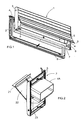
- Figure 1 illustrates an example of a letterbox 1 according to the invention.
- the letterbox comprises an outer section 2 and an inner section 3. Both sections contain flaps.
- the example in Figure 1 comprises a telescopic shaft 4 connecting the outer and inner sections.
- the invention is also applicable to letterboxes that have no telescopic shaft but comprise separate outer 2 and inner 3 sections.
- the inner flap 5 in the inner section 3 is open, showing the bezel surface 7 surrounding the letterbox opening and the projections 6.
- the letterbox opening refers to the opening through which mail can be pushed in.
- the projections 6 hold the inner flap slightly open when it is in the closed position.
- the projections are fitted or can be fitted on the bezel surface 7 of the inner section.
- a good position for the projections is on the bezel surface 7 of the inner section 3 on the side of the opening edge 9 of the inner flap 5.
- the projections can also be fitted on the inner surface of the inner flap 5.
- the side of the opening edge 9 of the inner flap 5 is a good position.
- a good size of gap is one that allows a single A4 sheet or a sheaf of sheets to be pushed in with ease.
- the inner section 3 and its bezel surface 7 provide better control of tightness compared to direct mounting of the inner flap on the inside of the door as known from prior art.
- the main air flows go through the letterbox opening, the size of which can be influenced by the shape and interoperation of the inner section 3 and the flap 5 fitted to it.
- the gap formed using the projections 6 is created in a controlled manner and only allows a certain permissible air flow.
- the gap reduces tightness, but good control of tightness and the structures of the front section 2 still make it possible to achieve the required level of tightness. Minor leakage air flow can occur through the gap between the inner section 3 and the mounting base but this is not as significant as the flow through the gap created by the projections.
- Both the front section 2 and the back section 3 have a bezel surface 7 surrounding the letterbox opening.
- the bezel surface is also parallel to the inner surface of the flap 5, 21, making the flap settle against the bezel surface as evenly as possible. It is also preferable that the bezel surface is at least essentially parallel to the mounting base. This makes the structure of the sections flat, and they will not protrude from the surface of the mounting base by any great amount.
- Sealing strip or strips 8 are fitted or can be fitted on the back surface of the outer section 2 ⁇ that is, the surface that faces the mounting base upon installation ⁇ so that they form a closed loop.
- the loop of sealing strips prevents leak air flow through the gap between the outer section and the mounting base.
- the outer section 2 comprises an insulation layer 22 on the inner surface of the outer flap 21 that covers the opening surrounded by the outer section's bezel surface 7 when the outer flap is closed.
- Figure 2 illustrates the insulation layer 22. The purpose of this is to prevent air flow through the letterbox.
- the example in Figure 2 also illustrates a telescopic shaft section 4A included in the outer section 2.
- An expanding fire insulation strip 23 can be fitted parallel to the long edge of the telescopic shaft.
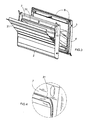
- Figure 3 illustrates an example of a letterbox according to the invention in which the bezel surface 7 of the outer section 2 comprises a ridge 31 surrounding the letterbox opening.
- the ridge improves the tightness properties of the front section as the insulation layer 22 of the front flap 21 settles very tightly against the ridge 31 when closed.
- Figure 4 shows an enlargement of Figure 3 .
- the opening sector of the outer flap 21 in the outer section 2 is upwards and, correspondingly, the opening sector of the inner flap 5 in the inner section 3 is downwards.
- the opening edges 9 of both the outer and inner flaps are bent to facilitate opening.
- the outer and inner flaps are held in the closed position by flap-specific springs (not shown in the figures). The springs will also return the flaps to the closed position after being opened.
- the inner section 3 may comprise sealing strips 8 that are fitted or can be fitted on the surfaces of the inner section facing the mounting base upon installation of the inner section 3 and that form a closed loop. Springs or other means are used for the purpose of holding the flaps in the closed position and returning them to that position.
- the invention is applicable for use on mounting bases with a straight or inclined machined opening. Even though the concept of tightness has been used in the above mostly to refer to tightness against air flows, tightness also has other effects.
- the structures and the materials used in them also block the conveyance of fire, heat, sounds and smells. Sealants are significant for blocking such conveyance. All materials are suitable for the purpose.
- the structures of the inner and outer sections are manufactured of a suitable plastic and/or metal, such as aluminium. If and when the projections 6 are made of an elastic material, they are more efficient in reducing the noise arising from the closure of the inner flap.
- the projections can also be machined directly on the base (the bezel surface or the flap); thus, they are of the same material as the base.
Landscapes
- Supports Or Holders For Household Use (AREA)
- Specific Sealing Or Ventilating Devices For Doors And Windows (AREA)
- Air Bags (AREA)
- Rear-View Mirror Devices That Are Mounted On The Exterior Of The Vehicle (AREA)
- Fluid-Damping Devices (AREA)
Abstract
Description
- The present invention relates to a slot-type letterbox. In particular, the invention relates to a slot-type letterbox for mounting on doors as for example disclosed in
GB 2 291 680 A - Prior art letterboxes with springs holding the flaps in the closed position or flaps that are otherwise heavy to open make it difficult to insert thin sheets such as advertising leaflets or various notices. A thin leaflet is not rigid enough to push the inner flap open; the leaflet will become kinked. In order to push the leaflet to the inside of the door through the slot, one must try to open the inner flap slightly with fingers, for example.
On the other hand, fire protection regulations require that a letterbox must fulfil certain criteria for preventing the spreading of fire. In the closed position, the inner flap of a prior art letterbox serves as a fire-protection structure. - The objective of the invention is to create a letterbox through which a thin leaflet can be pushed with ease. Furthermore, the letterbox must fulfil the regulatory criteria for fire protection. The objectives will be achieved as described in the independent claim. The dependent claims describe various embodiments of the invention.
- In an embodiment according to the invention, a small gap remains between the inner surface of the
inner flap 5 and the other structures of theinner section 3, allowing a thin leaflet to be pushed inside the door with ease. Theinner section 3 comprisesprojections 6 that hold theinner flap 5 slightly open when it is in the closed position. In order to improve control of the tightness properties of the inner section, theinner section 3 comprises abezel surface 7 surrounding the letterbox opening. The bezel surface is parallel to the inner surface of theflap 5 in theinner section 3. - The
outer section 2 also comprises acorresponding bezel surface 7 surrounding the letterbox opening. Theouter section 2 also comprises a sealing strip orstrips 8 that are fitted or can be fitted on the surfaces of the outer section facing the mounting base upon installation and that form a closed loop. Furthermore, the inner surface of theouter flap 21 in theouter section 2 comprises aninsulation layer 22 that covers the opening surrounded by thebezel surface 7 when the outer flap is closed. - In the following, the invention is described in more detail by reference to the enclosed drawings, where
-
Figure 1 illustrates an example of a letterbox according to the invention, -
Figure 2 illustrates an example of the outer section of a letterbox according to the invention, -
Figure 3 illustrates an example of a letterbox according to the invention, and -
Figure 4 shows an enlarged view of a detail inFigure 3 . -
Figure 1 illustrates an example of a letterbox 1 according to the invention. The letterbox comprises anouter section 2 and aninner section 3. Both sections contain flaps. Furthermore, the example inFigure 1 comprises atelescopic shaft 4 connecting the outer and inner sections. However, it should be noted that the invention is also applicable to letterboxes that have no telescopic shaft but comprise separate outer 2 and inner 3 sections.
InFigure 1 , theinner flap 5 in theinner section 3 is open, showing thebezel surface 7 surrounding the letterbox opening and theprojections 6. The letterbox opening refers to the opening through which mail can be pushed in. Theprojections 6 hold the inner flap slightly open when it is in the closed position. In the example ofFigure 1 , the projections are fitted or can be fitted on thebezel surface 7 of the inner section. A good position for the projections is on thebezel surface 7 of theinner section 3 on the side of the opening edge 9 of theinner flap 5. The projections can also be fitted on the inner surface of theinner flap 5. Also in this case, the side of the opening edge 9 of theinner flap 5 is a good position. A good size of gap is one that allows a single A4 sheet or a sheaf of sheets to be pushed in with ease.
Theinner section 3 and itsbezel surface 7 provide better control of tightness compared to direct mounting of the inner flap on the inside of the door as known from prior art. The main air flows go through the letterbox opening, the size of which can be influenced by the shape and interoperation of theinner section 3 and theflap 5 fitted to it. Thus the gap formed using theprojections 6 is created in a controlled manner and only allows a certain permissible air flow. In principle and in practice, the gap reduces tightness, but good control of tightness and the structures of thefront section 2 still make it possible to achieve the required level of tightness. Minor leakage air flow can occur through the gap between theinner section 3 and the mounting base but this is not as significant as the flow through the gap created by the projections.
Both thefront section 2 and theback section 3 have abezel surface 7 surrounding the letterbox opening. The bezel surface is also parallel to the inner surface of theflap - Sealing strip or
strips 8 are fitted or can be fitted on the back surface of theouter section 2 ― that is, the surface that faces the mounting base upon installation ― so that they form a closed loop. The loop of sealing strips prevents leak air flow through the gap between the outer section and the mounting base. Furthermore, theouter section 2 comprises aninsulation layer 22 on the inner surface of theouter flap 21 that covers the opening surrounded by the outer section'sbezel surface 7 when the outer flap is closed.Figure 2 illustrates theinsulation layer 22. The purpose of this is to prevent air flow through the letterbox. The example inFigure 2 also illustrates atelescopic shaft section 4A included in theouter section 2. An expandingfire insulation strip 23 can be fitted parallel to the long edge of the telescopic shaft. -
Figure 3 illustrates an example of a letterbox according to the invention in which thebezel surface 7 of theouter section 2 comprises aridge 31 surrounding the letterbox opening. The ridge improves the tightness properties of the front section as theinsulation layer 22 of thefront flap 21 settles very tightly against theridge 31 when closed.Figure 4 shows an enlargement ofFigure 3 .
In the examples, the opening sector of theouter flap 21 in theouter section 2 is upwards and, correspondingly, the opening sector of theinner flap 5 in theinner section 3 is downwards. The opening edges 9 of both the outer and inner flaps are bent to facilitate opening. The outer and inner flaps are held in the closed position by flap-specific springs (not shown in the figures). The springs will also return the flaps to the closed position after being opened. However, it should be noted that the invention is not limited to these examples but the embodiment specified in Claim 1 is essential as regards the invention. For example, theinner section 3 may comprise sealingstrips 8 that are fitted or can be fitted on the surfaces of the inner section facing the mounting base upon installation of theinner section 3 and that form a closed loop. Springs or other means are used for the purpose of holding the flaps in the closed position and returning them to that position. The invention is applicable for use on mounting bases with a straight or inclined machined opening.
Even though the concept of tightness has been used in the above mostly to refer to tightness against air flows, tightness also has other effects. The structures and the materials used in them also block the conveyance of fire, heat, sounds and smells. Sealants are significant for blocking such conveyance. All materials are suitable for the purpose. For example, the structures of the inner and outer sections are manufactured of a suitable plastic and/or metal, such as aluminium. If and when theprojections 6 are made of an elastic material, they are more efficient in reducing the noise arising from the closure of the inner flap. The projections can also be machined directly on the base (the bezel surface or the flap); thus, they are of the same material as the base. - It is evident that the invention is not limited to the embodiments mentioned in this text.
Claims (9)
- A slot-type letterbox comprising an outer section (2) containing an outer flap (21) and an inner section (3) containing an inner flap (5), the inner section (3) and the outer section (2) comprise a bezel surface (7) surrounding the letterbox opening, said bezel surface being parallel to the inner surface of the flap contained in the corresponding section when the flap settles against the bezel surface (7);
at least the outer section (2) comprises a sealing strip or strips (8) that are fitted or can be fitted on the surfaces of the outer section facing a mounting base upon installation of the outer section and that form a closed loop;
characterised in that
the outer section (2) additionally comprises an insulation layer (22) on the inner surface of the outer flap (21), covering the opening surrounded by the bezel surface (7) when the outer flap is dosed;
the inner section (3) additionally comprises projections (6) holding the inner flap (5) slightly open when it is in the closed position. - A letterbox according to Claim 1, characterised in that the bezel surface (7) of the outer section (2) comprises a ridge (31) surrounding the letterbox opening.
- A letterbox according to Claim 1 or 2, characterised in that the projections (6) are located on the bezel surface (7) of the inner section (3) on the side of the opening edge (9) of the inner flap (5).
- A letterbox according to Claim 1 or 2, characterised in that the projections (6) are located on the inner surface of the inner flap (3) on the side of its opening edge (9).
- A letterbox according to Claim 3 or 4, characterised in that the projections (6) are made of an elastic material.
- A letterbox according to any of the Claims 1, 2, 3, 4 and 5, characterised in that the inner section (3) comprises sealing strips (8) that are fitted or can be fitted on the surfaces of the inner section facing the mounting base upon installation of the inner section (3) and that form a closed loop.
- A letterbox according to any of the Claims 1 to 6, characterised in that it comprises a telescopic shaft.
- A letterbox according to any of the Claims 1 to 7, characterised in that the letterbox can be installed in a straight machined opening or in an inclined machined opening.
- A letterbox according to any of the Claims 1 to 8, characterised in that it comprises springs to hold the outer and inner flaps in the closed position and return them to said position.
Applications Claiming Priority (1)
| Application Number | Priority Date | Filing Date | Title |
|---|---|---|---|
| FI20055341A FI121327B (en) | 2005-06-23 | 2005-06-23 | Letterbox |
Publications (2)
| Publication Number | Publication Date |
|---|---|
| EP1736080A1 EP1736080A1 (en) | 2006-12-27 |
| EP1736080B1 true EP1736080B1 (en) | 2011-06-29 |
Family
ID=34778477
Family Applications (1)
| Application Number | Title | Priority Date | Filing Date |
|---|---|---|---|
| EP06115341A Active EP1736080B1 (en) | 2005-06-23 | 2006-06-13 | Slot-type letterbox |
Country Status (4)
| Country | Link |
|---|---|
| EP (1) | EP1736080B1 (en) |
| AT (1) | ATE514361T1 (en) |
| FI (1) | FI121327B (en) |
| RU (1) | RU2391035C2 (en) |
Families Citing this family (3)
| Publication number | Priority date | Publication date | Assignee | Title |
|---|---|---|---|---|
| GB2521449B (en) * | 2013-12-20 | 2017-05-03 | Trojan Hardware & Design Ltd | Improvements in or relating to letter plate arrangements |
| GB2565275B (en) * | 2017-07-26 | 2020-08-19 | Uap Ltd | Improvements to letter-plates |
| GB2637758A (en) * | 2024-02-02 | 2025-08-06 | Rutland Trading Co Ltd | A letterplate assembly |
Family Cites Families (8)
| Publication number | Priority date | Publication date | Assignee | Title |
|---|---|---|---|---|
| GB929250A (en) * | 1960-04-22 | 1963-06-19 | Hyresgaesternas Sparkasse Och | Improvements in or relating to letter boxes |
| SE345195B (en) * | 1968-04-10 | 1972-05-23 | Hasselberg S | |
| SU1230928A1 (en) * | 1984-04-26 | 1986-05-15 | Каунасский Филиал Специального Проектно-Конструкторского Бюро Министерства Связи Ссср | Letter box |
| CA1241624A (en) * | 1984-07-19 | 1988-09-06 | Leo A. Saint Pierre | Insulated letter drop plate |
| GB2291680B (en) * | 1994-07-22 | 1997-10-22 | Paddock Fabr Ltd | Letter plate assembly |
| DE29701740U1 (en) * | 1997-02-01 | 1997-05-15 | Müller, Horst, 32361 Preußisch Oldendorf | Letter slot with flap |
| NL1007771C2 (en) * | 1997-12-11 | 1999-06-23 | Jansen Spec Prod Bv | Mailbox assembly. |
| RU2233606C1 (en) * | 2003-09-25 | 2004-08-10 | Гой Владимир Леонтьевич | Letter-box |
-
2005
- 2005-06-23 FI FI20055341A patent/FI121327B/en active IP Right Grant
-
2006
- 2006-06-13 AT AT06115341T patent/ATE514361T1/en not_active IP Right Cessation
- 2006-06-13 EP EP06115341A patent/EP1736080B1/en active Active
- 2006-06-22 RU RU2006122354/12A patent/RU2391035C2/en active
Also Published As
| Publication number | Publication date |
|---|---|
| FI20055341A0 (en) | 2005-06-23 |
| RU2391035C2 (en) | 2010-06-10 |
| EP1736080A1 (en) | 2006-12-27 |
| FI20055341L (en) | 2006-12-24 |
| ATE514361T1 (en) | 2011-07-15 |
| RU2006122354A (en) | 2008-01-10 |
| FI121327B (en) | 2010-10-15 |
Similar Documents
| Publication | Publication Date | Title |
|---|---|---|
| US11629548B2 (en) | Pet door apparatus | |
| CA2239539A1 (en) | Package with attached leaflet | |
| CN104818936B (en) | Sealing device | |
| CA2478441A1 (en) | Container with a lid | |
| JP2010255388A (en) | Door | |
| US4625457A (en) | Insulating member for double doors | |
| CA2453018A1 (en) | Air shutter and installation method thereof | |
| EP1736080A1 (en) | Slot-type letterbox | |
| CA2141356A1 (en) | Fume hood with air foil member | |
| US20050051663A1 (en) | Toilet paper dispenser | |
| US20080295286A1 (en) | Hinge Cover Assembly | |
| CA2279475A1 (en) | Control box door/fairing for front grille of an air conditioner | |
| JP3927191B2 (en) | Steel door mailbox and steel door having the same | |
| FI121729B (en) | cover letter | |
| US6705048B2 (en) | Magnetic weatherstrip | |
| MX2010002390A (en) | Vent apparatus. | |
| US8241380B2 (en) | Air filter duct cover | |
| GB2165876A (en) | Smoke-prevention doors | |
| US5473842A (en) | Rooftop access system | |
| CN210107065U (en) | Gas pressure regulating cabinet | |
| JPS63118480A (en) | Business refrigerator and closing device for doorway of refrigerator | |
| NO952036L (en) | Tilluftinnretning | |
| GB2347173A (en) | Sealing device attachable to existing letter box flap | |
| FI115604B (en) | Letter hatch fire-blocking arrangements combination | |
| KR19980059729U (en) | Air Conditioning Piping Cap |
Legal Events
| Date | Code | Title | Description |
|---|---|---|---|
| PUAI | Public reference made under article 153(3) epc to a published international application that has entered the european phase |
Free format text: ORIGINAL CODE: 0009012 |
|
| AK | Designated contracting states |
Kind code of ref document: A1 Designated state(s): AT BE BG CH CY CZ DE DK EE ES FI FR GB GR HU IE IS IT LI LT LU LV MC NL PL PT RO SE SI SK TR |
|
| AX | Request for extension of the european patent |
Extension state: AL BA HR MK YU |
|
| 17P | Request for examination filed |
Effective date: 20070105 |
|
| AKX | Designation fees paid |
Designated state(s): AT BE BG CH CY CZ DE DK EE ES FI FR GB GR HU IE IS IT LI LT LU LV MC NL PL PT RO SE SI SK TR |
|
| GRAP | Despatch of communication of intention to grant a patent |
Free format text: ORIGINAL CODE: EPIDOSNIGR1 |
|
| GRAS | Grant fee paid |
Free format text: ORIGINAL CODE: EPIDOSNIGR3 |
|
| GRAA | (expected) grant |
Free format text: ORIGINAL CODE: 0009210 |
|
| AK | Designated contracting states |
Kind code of ref document: B1 Designated state(s): AT BE BG CH CY CZ DE DK EE ES FI FR GB GR HU IE IS IT LI LT LU LV MC NL PL PT RO SE SI SK TR |
|
| REG | Reference to a national code |
Ref country code: GB Ref legal event code: FG4D |
|
| REG | Reference to a national code |
Ref country code: CH Ref legal event code: EP |
|
| REG | Reference to a national code |
Ref country code: IE Ref legal event code: FG4D |
|
| REG | Reference to a national code |
Ref country code: DE Ref legal event code: R096 Ref document number: 602006022750 Country of ref document: DE Effective date: 20110825 |
|
| REG | Reference to a national code |
Ref country code: SE Ref legal event code: TRGR |
|
| REG | Reference to a national code |
Ref country code: NL Ref legal event code: VDEP Effective date: 20110629 |
|
| PG25 | Lapsed in a contracting state [announced via postgrant information from national office to epo] |
Ref country code: LT Free format text: LAPSE BECAUSE OF FAILURE TO SUBMIT A TRANSLATION OF THE DESCRIPTION OR TO PAY THE FEE WITHIN THE PRESCRIBED TIME-LIMIT Effective date: 20110629 |
|
| PG25 | Lapsed in a contracting state [announced via postgrant information from national office to epo] |
Ref country code: LV Free format text: LAPSE BECAUSE OF FAILURE TO SUBMIT A TRANSLATION OF THE DESCRIPTION OR TO PAY THE FEE WITHIN THE PRESCRIBED TIME-LIMIT Effective date: 20110629 Ref country code: GR Free format text: LAPSE BECAUSE OF FAILURE TO SUBMIT A TRANSLATION OF THE DESCRIPTION OR TO PAY THE FEE WITHIN THE PRESCRIBED TIME-LIMIT Effective date: 20110930 Ref country code: SI Free format text: LAPSE BECAUSE OF FAILURE TO SUBMIT A TRANSLATION OF THE DESCRIPTION OR TO PAY THE FEE WITHIN THE PRESCRIBED TIME-LIMIT Effective date: 20110629 Ref country code: AT Free format text: LAPSE BECAUSE OF FAILURE TO SUBMIT A TRANSLATION OF THE DESCRIPTION OR TO PAY THE FEE WITHIN THE PRESCRIBED TIME-LIMIT Effective date: 20110629 Ref country code: FI Free format text: LAPSE BECAUSE OF FAILURE TO SUBMIT A TRANSLATION OF THE DESCRIPTION OR TO PAY THE FEE WITHIN THE PRESCRIBED TIME-LIMIT Effective date: 20110629 |
|
| PG25 | Lapsed in a contracting state [announced via postgrant information from national office to epo] |
Ref country code: BE Free format text: LAPSE BECAUSE OF FAILURE TO SUBMIT A TRANSLATION OF THE DESCRIPTION OR TO PAY THE FEE WITHIN THE PRESCRIBED TIME-LIMIT Effective date: 20110629 |
|
| PG25 | Lapsed in a contracting state [announced via postgrant information from national office to epo] |
Ref country code: CZ Free format text: LAPSE BECAUSE OF FAILURE TO SUBMIT A TRANSLATION OF THE DESCRIPTION OR TO PAY THE FEE WITHIN THE PRESCRIBED TIME-LIMIT Effective date: 20110629 Ref country code: IS Free format text: LAPSE BECAUSE OF FAILURE TO SUBMIT A TRANSLATION OF THE DESCRIPTION OR TO PAY THE FEE WITHIN THE PRESCRIBED TIME-LIMIT Effective date: 20111029 Ref country code: PT Free format text: LAPSE BECAUSE OF FAILURE TO SUBMIT A TRANSLATION OF THE DESCRIPTION OR TO PAY THE FEE WITHIN THE PRESCRIBED TIME-LIMIT Effective date: 20111031 Ref country code: NL Free format text: LAPSE BECAUSE OF FAILURE TO SUBMIT A TRANSLATION OF THE DESCRIPTION OR TO PAY THE FEE WITHIN THE PRESCRIBED TIME-LIMIT Effective date: 20110629 |
|
| REG | Reference to a national code |
Ref country code: EE Ref legal event code: FG4A Ref document number: E005993 Country of ref document: EE Effective date: 20110926 |
|
| PG25 | Lapsed in a contracting state [announced via postgrant information from national office to epo] |
Ref country code: PL Free format text: LAPSE BECAUSE OF FAILURE TO SUBMIT A TRANSLATION OF THE DESCRIPTION OR TO PAY THE FEE WITHIN THE PRESCRIBED TIME-LIMIT Effective date: 20110629 Ref country code: CY Free format text: LAPSE BECAUSE OF FAILURE TO SUBMIT A TRANSLATION OF THE DESCRIPTION OR TO PAY THE FEE WITHIN THE PRESCRIBED TIME-LIMIT Effective date: 20110629 Ref country code: RO Free format text: LAPSE BECAUSE OF FAILURE TO SUBMIT A TRANSLATION OF THE DESCRIPTION OR TO PAY THE FEE WITHIN THE PRESCRIBED TIME-LIMIT Effective date: 20110629 Ref country code: SK Free format text: LAPSE BECAUSE OF FAILURE TO SUBMIT A TRANSLATION OF THE DESCRIPTION OR TO PAY THE FEE WITHIN THE PRESCRIBED TIME-LIMIT Effective date: 20110629 Ref country code: IT Free format text: LAPSE BECAUSE OF FAILURE TO SUBMIT A TRANSLATION OF THE DESCRIPTION OR TO PAY THE FEE WITHIN THE PRESCRIBED TIME-LIMIT Effective date: 20110629 |
|
| PLBE | No opposition filed within time limit |
Free format text: ORIGINAL CODE: 0009261 |
|
| STAA | Information on the status of an ep patent application or granted ep patent |
Free format text: STATUS: NO OPPOSITION FILED WITHIN TIME LIMIT |
|
| 26N | No opposition filed |
Effective date: 20120330 |
|
| PG25 | Lapsed in a contracting state [announced via postgrant information from national office to epo] |
Ref country code: DK Free format text: LAPSE BECAUSE OF FAILURE TO SUBMIT A TRANSLATION OF THE DESCRIPTION OR TO PAY THE FEE WITHIN THE PRESCRIBED TIME-LIMIT Effective date: 20110629 |
|
| REG | Reference to a national code |
Ref country code: DE Ref legal event code: R097 Ref document number: 602006022750 Country of ref document: DE Effective date: 20120330 |
|
| PG25 | Lapsed in a contracting state [announced via postgrant information from national office to epo] |
Ref country code: MC Free format text: LAPSE BECAUSE OF NON-PAYMENT OF DUE FEES Effective date: 20120630 |
|
| REG | Reference to a national code |
Ref country code: CH Ref legal event code: PL |
|
| REG | Reference to a national code |
Ref country code: CH Ref legal event code: PL |
|
| GBPC | Gb: european patent ceased through non-payment of renewal fee |
Effective date: 20120613 |
|
| REG | Reference to a national code |
Ref country code: IE Ref legal event code: MM4A |
|
| REG | Reference to a national code |
Ref country code: FR Ref legal event code: ST Effective date: 20130228 |
|
| REG | Reference to a national code |
Ref country code: DE Ref legal event code: R119 Ref document number: 602006022750 Country of ref document: DE Effective date: 20130101 |
|
| PG25 | Lapsed in a contracting state [announced via postgrant information from national office to epo] |
Ref country code: GB Free format text: LAPSE BECAUSE OF NON-PAYMENT OF DUE FEES Effective date: 20120613 Ref country code: CH Free format text: LAPSE BECAUSE OF NON-PAYMENT OF DUE FEES Effective date: 20120630 Ref country code: DE Free format text: LAPSE BECAUSE OF NON-PAYMENT OF DUE FEES Effective date: 20130101 Ref country code: IE Free format text: LAPSE BECAUSE OF NON-PAYMENT OF DUE FEES Effective date: 20120613 Ref country code: FR Free format text: LAPSE BECAUSE OF NON-PAYMENT OF DUE FEES Effective date: 20120702 Ref country code: LI Free format text: LAPSE BECAUSE OF NON-PAYMENT OF DUE FEES Effective date: 20120630 Ref country code: ES Free format text: LAPSE BECAUSE OF FAILURE TO SUBMIT A TRANSLATION OF THE DESCRIPTION OR TO PAY THE FEE WITHIN THE PRESCRIBED TIME-LIMIT Effective date: 20111010 |
|
| PG25 | Lapsed in a contracting state [announced via postgrant information from national office to epo] |
Ref country code: BG Free format text: LAPSE BECAUSE OF FAILURE TO SUBMIT A TRANSLATION OF THE DESCRIPTION OR TO PAY THE FEE WITHIN THE PRESCRIBED TIME-LIMIT Effective date: 20110929 |
|
| PG25 | Lapsed in a contracting state [announced via postgrant information from national office to epo] |
Ref country code: TR Free format text: LAPSE BECAUSE OF FAILURE TO SUBMIT A TRANSLATION OF THE DESCRIPTION OR TO PAY THE FEE WITHIN THE PRESCRIBED TIME-LIMIT Effective date: 20110629 |
|
| PG25 | Lapsed in a contracting state [announced via postgrant information from national office to epo] |
Ref country code: LU Free format text: LAPSE BECAUSE OF NON-PAYMENT OF DUE FEES Effective date: 20120613 |
|
| PG25 | Lapsed in a contracting state [announced via postgrant information from national office to epo] |
Ref country code: HU Free format text: LAPSE BECAUSE OF FAILURE TO SUBMIT A TRANSLATION OF THE DESCRIPTION OR TO PAY THE FEE WITHIN THE PRESCRIBED TIME-LIMIT Effective date: 20060613 |
|
| P01 | Opt-out of the competence of the unified patent court (upc) registered |
Effective date: 20230826 |
|
| PGFP | Annual fee paid to national office [announced via postgrant information from national office to epo] |
Ref country code: EE Payment date: 20250528 Year of fee payment: 20 |
|
| PGFP | Annual fee paid to national office [announced via postgrant information from national office to epo] |
Ref country code: SE Payment date: 20250514 Year of fee payment: 20 |