EP1735834B1 - Led matrix current control - Google Patents
Led matrix current control Download PDFInfo
- Publication number
- EP1735834B1 EP1735834B1 EP05730185.5A EP05730185A EP1735834B1 EP 1735834 B1 EP1735834 B1 EP 1735834B1 EP 05730185 A EP05730185 A EP 05730185A EP 1735834 B1 EP1735834 B1 EP 1735834B1
- Authority
- EP
- European Patent Office
- Prior art keywords
- resistor
- amplifier
- light source
- leds
- parallel
- Prior art date
- Legal status (The legal status is an assumption and is not a legal conclusion. Google has not performed a legal analysis and makes no representation as to the accuracy of the status listed.)
- Expired - Lifetime
Links
- 239000011159 matrix material Substances 0.000 title claims description 12
- 239000003990 capacitor Substances 0.000 claims description 14
- 238000012544 monitoring process Methods 0.000 claims description 7
- 230000007423 decrease Effects 0.000 claims description 3
- 230000001105 regulatory effect Effects 0.000 description 5
- 238000000034 method Methods 0.000 description 3
- 101710198350 Snaclec 1 Proteins 0.000 description 1
- 230000032683 aging Effects 0.000 description 1
- 239000003985 ceramic capacitor Substances 0.000 description 1
- 238000006243 chemical reaction Methods 0.000 description 1
- 238000010586 diagram Methods 0.000 description 1
- 238000003780 insertion Methods 0.000 description 1
- 230000037431 insertion Effects 0.000 description 1
- 230000010363 phase shift Effects 0.000 description 1
Images



Classifications
-
- H—ELECTRICITY
- H05—ELECTRIC TECHNIQUES NOT OTHERWISE PROVIDED FOR
- H05B—ELECTRIC HEATING; ELECTRIC LIGHT SOURCES NOT OTHERWISE PROVIDED FOR; CIRCUIT ARRANGEMENTS FOR ELECTRIC LIGHT SOURCES, IN GENERAL
- H05B45/00—Circuit arrangements for operating light-emitting diodes [LED]
- H05B45/10—Controlling the intensity of the light
-
- H—ELECTRICITY
- H05—ELECTRIC TECHNIQUES NOT OTHERWISE PROVIDED FOR
- H05B—ELECTRIC HEATING; ELECTRIC LIGHT SOURCES NOT OTHERWISE PROVIDED FOR; CIRCUIT ARRANGEMENTS FOR ELECTRIC LIGHT SOURCES, IN GENERAL
- H05B45/00—Circuit arrangements for operating light-emitting diodes [LED]
- H05B45/10—Controlling the intensity of the light
- H05B45/14—Controlling the intensity of the light using electrical feedback from LEDs or from LED modules
-
- H—ELECTRICITY
- H05—ELECTRIC TECHNIQUES NOT OTHERWISE PROVIDED FOR
- H05B—ELECTRIC HEATING; ELECTRIC LIGHT SOURCES NOT OTHERWISE PROVIDED FOR; CIRCUIT ARRANGEMENTS FOR ELECTRIC LIGHT SOURCES, IN GENERAL
- H05B45/00—Circuit arrangements for operating light-emitting diodes [LED]
- H05B45/30—Driver circuits
- H05B45/37—Converter circuits
- H05B45/3725—Switched mode power supply [SMPS]
-
- Y—GENERAL TAGGING OF NEW TECHNOLOGICAL DEVELOPMENTS; GENERAL TAGGING OF CROSS-SECTIONAL TECHNOLOGIES SPANNING OVER SEVERAL SECTIONS OF THE IPC; TECHNICAL SUBJECTS COVERED BY FORMER USPC CROSS-REFERENCE ART COLLECTIONS [XRACs] AND DIGESTS
- Y02—TECHNOLOGIES OR APPLICATIONS FOR MITIGATION OR ADAPTATION AGAINST CLIMATE CHANGE
- Y02B—CLIMATE CHANGE MITIGATION TECHNOLOGIES RELATED TO BUILDINGS, e.g. HOUSING, HOUSE APPLIANCES OR RELATED END-USER APPLICATIONS
- Y02B20/00—Energy efficient lighting technologies, e.g. halogen lamps or gas discharge lamps
- Y02B20/30—Semiconductor lamps, e.g. solid state lamps [SSL] light emitting diodes [LED] or organic LED [OLED]
Definitions
- the present invention relates to a temperature dependant current sense circuit for a substantially constant intensity light source. Specifically, the present invention relates to a current sense circuit for a LED matrix for use in signal lights such as traffic lights.
- the light-emitting diode produces light when a forward current flows thru its P-N junction.
- the intensity of the emitted light is directly proportional to the forward current, I F , and is maintained constant by regulating I F .
- I F forward current
- Changing I f according to the temperature profile of the LED performs thermal compensation of the light intensity.
- the light-emitting diode can be driven by a constant voltage, V F , to get the desired forward current, I F , or to regulate directly I F .
- V F constant voltage
- I F /V F variable voltage
- the non-linear electrical characteristic of I F /V F has a logarithmic profile. Regulating I F by using the voltage driven method will result to non-linear variations of I F for any variations of V F , such as initial, temperature and aging variations. Regulating directly I F overcomes the non-linearity mentioned above and this is the selected method used in the prior art.
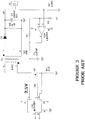
- Thermal compensation is performed at the level of R S , see Figure 2 , i.e. the equivalent resistance value R S is the result of the combination of a thermistor in parallel with a resistor and in series with another resistor. The selection of these components' value determines the required thermal profile of the LED lamp.
- the conventional LED current sense circuit has been used for 5mm LED lamps.
- the LED array (not shown in Figure 2 ) is fed via J1 and the lamp current returns back to the power transformer through the current sense resistor, R S .
- the controller CTL drives Q1 in such a way that the voltage at pin 1 of CTL is maintained at 2.5V (+2.5V internal reference). In steady state, the voltage across R S is 2.5 V dc and the current flowing through it is determined by its resistance value.
- the resistance value of R S is 25 ohms and the lamp current is regulated to 100 mA.
- the power dissipation in the sense resistor R S is 0.25W (100 mA through 25 ohms).
- Conventional current sense circuits in this context are disclosed in patent publications US 6,400,102 B1 (Ghanem ) and US 6,285,139 B1 (Ghanem ).
- the load current that must be sensed is in the order of 1A and the power dissipation of R S would be 2.5W thus reducing the efficiency of the power supply.
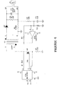
- One way to reduce the power loss is to reduce the current sense resistance and to amplify the sensed voltage, as shown in Figure 3 .
- PFC power factor control
- Insertion of the integrated power factor controller circuit in an electrical power supply system enables easy and efficient control of the power factor and level of current harmonics.
- controllers such as controller MC33262 from Motorola.
- the controller draws current from the ac source in proportion to the sinusoidal voltage. This automatically causes the current waveform to be sinusoidal and in phase with the line voltage waveform.
- a PFC circuit has the drawback of having voltage ripple across the output filter capacitor at twice the line frequency. A certain amount of that voltage ripple appears across the current sense resistor and pin 1 of CTL.
- a fixed LED output current presents the following drawbacks: at higher temperature the output LED light intensity decreases; at lower temperature the output LED light intensity increases.
- One object of the present invention is to thermally regulate the output current, and thus the light intensity, of a non-linear high-power light-emitting load.
- One object of the present invention is an improved circuit.
- a substantially constant intensity light source including: functional circuitry, said functional circuity comprising a switching power supply outputting at least one signal, said signal driving a matrix of LEDs connected in series and parallel and configured for redundancy, and a monitoring circuit, said monitoring circuit including a current sense circuit.
- the current sense circuit includes an amplifier and at least one resistor in series with the amplifier input. The current sense circuit senses the total current of a flyback diode of the switching power supply, recovers a dc component of the total current via a low pass filter and provides feedback control of the at least one signal.
- the inventive current sensing circuit is preferably used with signal lights for traffic lights.
- each signal light is made up of a matrix of high brightness LEDs connected in series and parallel and configured for redundancy.
- the inventive circuitry module includes functional circuitry, an LED light source array connected in series and parallel and configured for redundancy and a monitoring circuit.
- the functional circuitry preferably includes a switch mode power supply that converts 120 volts ac input voltage to an output constant current. For yellow LEDs, the output current is 900 mA. For red LEDs, the current output is 590 mA at 25°C and 800 mA at 74°C for green LEDs, the current output is 660 mA at 25°C and 670 mA at 74°C.
- the monitoring circuit is made of an LED current detector circuit that senses the LED's current. The LED's current is regulated by the power supply unit (PSU) feedback loop providing constant light flow.
- PSU power supply unit
- the present invention preferably utilizes a substantially constant intensity light source comprising: a non-linear light-emitting load; and a controllable dc voltage and current source for supplying the non-linear light-emitting load with dc voltage and current.
- a controllable source is a switching power supply.
- the inventive circuit provides a current-representative signal that may be used for feedback control of a non-linear load.
- Current feedback control is difficult with current sensor circuits that do not provide an output that varies with the condition of operation of the non-linear load.
- the invention described herein provides this feature in a simple low-cost circuit.
- Figure 4 shows an improved method and circuit to sense the load current and will overcome the drawbacks of the prior art circuits.
- the inventive circuit senses the current of the flyback diode D7 and recovers the dc component of the waveform via low pass filter R3/C3 (7 Hz).
- a small current sense transformer may be used in place of Rs for higher load current applications.
- the pole C7/R load changes with different load current and the voltage ripple across Rs changes for any variation of C7 (both initial and temperature variations).
- R3/C3 provides a pole that is independent of the pole C7/R load variations.
- the voltage ripple across C3 is completely independent of capacitor C7.
- C3 is preferably a X7R ceramic capacitor and has lower initial and temperature variations in comparison of the electrolytic capacitor C7.
- the turn-on and turn-off of the lamp is also improved since capacitance value of C7 can be much smaller, 470 uF instead 3,300uF for a 1A load.
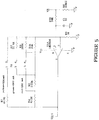
- FIG. 5-8 A detailed view of the current sense amplifier is shown in Figures 5-8 . That circuit allows for the selection of the current for the yellow, red or green LED configuration. The yellow, green or red current is selected by connecting the jumper at position 1-2, 3-4 or 5-6, respectively.
- This circuit compensates for the light reduction of the red and green LEDs at higher temperature by increasing the output current. This compensation is performed by thermistor R th where its resistivity decreases above 25°C, reducing the Op Amp gain and thus increasing the current across R s .
- the resistance is 25 K ⁇ at 25°C and 3.8 K ⁇ at 74°C.
- only one (1) thermistor is used for all the load configurations.
- the jumper is connected at S1-1 and 2, S1-3 and 4 or S1-5 and 6, respectively, as shown in Figure 5 .
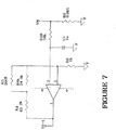
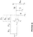
- the equivalent current sense circuit for a yellow signal, red signal or green signal is shown in detail in Figure 6 , Figure 7 and Figure 8 , respectively.
- the current across the yellow, a red or green LED matrix changes as the ambient temperature changes.
- the voltage at U1-1 is 2.5 Vdc.
Landscapes
- Circuit Arrangement For Electric Light Sources In General (AREA)
- Led Devices (AREA)
- Traffic Control Systems (AREA)
Description
- The present invention relates to a temperature dependant current sense circuit for a substantially constant intensity light source. Specifically, the present invention relates to a current sense circuit for a LED matrix for use in signal lights such as traffic lights.
- The light-emitting diode (LED) produces light when a forward current flows thru its P-N junction. The intensity of the emitted light is directly proportional to the forward current, IF, and is maintained constant by regulating IF. Changing If according to the temperature profile of the LED performs thermal compensation of the light intensity.
- The light-emitting diode (LED) can be driven by a constant voltage, VF, to get the desired forward current, IF, or to regulate directly IF. The non-linear electrical characteristic of IF/VF has a logarithmic profile. Regulating IF by using the voltage driven method will result to non-linear variations of IF for any variations of VF, such as initial, temperature and aging variations. Regulating directly IF overcomes the non-linearity mentioned above and this is the selected method used in the prior art. Thermal compensation is performed at the level of RS, see
Figure 2 , i.e. the equivalent resistance value RS is the result of the combination of a thermistor in parallel with a resistor and in series with another resistor. The selection of these components' value determines the required thermal profile of the LED lamp. - As shown in
Figure 2 , the conventional LED current sense circuit has been used for 5mm LED lamps. The LED array (not shown inFigure 2 ) is fed via J1 and the lamp current returns back to the power transformer through the current sense resistor, RS. The controller CTL drives Q1 in such a way that the voltage atpin 1 of CTL is maintained at 2.5V (+2.5V internal reference). In steady state, the voltage across RS is 2.5 Vdc and the current flowing through it is determined by its resistance value. In the example ofFigure 2 , the resistance value of RS is 25 ohms and the lamp current is regulated to 100 mA. The power dissipation in the sense resistor RS, as shown inFigure 3 , is 0.25W (100 mA through 25 ohms). Conventional current sense circuits in this context, are disclosed in patent publicationsUS 6,400,102 B1 (Ghanem ) andUS 6,285,139 B1 (Ghanem ). For a 1W LED applications, the load current that must be sensed is in the order of 1A and the power dissipation of RS would be 2.5W thus reducing the efficiency of the power supply. One way to reduce the power loss is to reduce the current sense resistance and to amplify the sensed voltage, as shown inFigure 3 . Using the resistor value of R1 and R2, for 1A load, the Op Amp gain is 38.5 (Gain = 2.5V/0.065V or Gain=1+R1/R2) and the power dissipation is only 65 mW (Pdiss = 0.065*12). - In addition to the constant light intensity requirement of Traffic Light units, power factor control (PFC) must be incorporated. Insertion of the integrated power factor controller circuit in an electrical power supply system enables easy and efficient control of the power factor and level of current harmonics. To obtain a power factor equal to unity, prior art systems use controllers such as controller
MC33262 pin 1 of CTL. In the case that the voltage atpin 1 of CTL exceeds 2.7 volt, CTL stops driving Q1 and distortion of the line current waveforms occurs thus increasing the ATHD (Line current Total Harmonic Distortion). The selection of the output filter capacitor value of C7 is thus very critical. Any reduction of the capacitor value due to the initial tolerance and temperature can lead to the scenario mentioned above under some load conditions. An extra pole (R3, C3) is also required to attenuate the 120 Hz ripple to maintain the peak voltage of CTL-1 below 2.7V. Moreover, in order to accommodate different loads, the resistance of R3 must be selected which is not a good practice for a high volume production. Further, the additional pole adds more phase shift at the crossover frequency of the feedback loop and may lead to instability. - A fixed LED output current presents the following drawbacks: at higher temperature the output LED light intensity decreases; at lower temperature the output LED light intensity increases. One object of the present invention is to thermally regulate the output current, and thus the light intensity, of a non-linear high-power light-emitting load.
- Secondly, prior art is very sensitive to the output capacitor variations that can lead to increase the ATHD and another object is to eliminate the concern associated to these variations.
- As more powerful LEDs are used in Traffic Light units, there is a need for a stable monitoring circuit. One object of the present invention is an improved circuit.
- Aspects of the invention are defined in the accompanying claims.
- There is provided a substantially constant intensity light source including: functional circuitry, said functional circuity comprising a switching power supply outputting at least one signal, said signal driving a matrix of LEDs connected in series and parallel and configured for redundancy, and a monitoring circuit, said monitoring circuit including a current sense circuit. The current sense circuit includes an amplifier and at least one resistor in series with the amplifier input. The current sense circuit senses the total current of a flyback diode of the switching power supply, recovers a dc component of the total current via a low pass filter and provides feedback control of the at least one signal.
- The objects, advantages and other features of the present invention will become more apparent upon reading of the following non-restrictive description of a preferred embodiment thereof, given by way of example only with reference to the accompanying drawings.
-
-
Figure 1 is a block diagram of an LED traffic light. -
Figure 2 is a prior art current sense circuit. -
Figure 3 is a prior art current sense circuit. -
Figure 4 is one embodiment of a current sense circuit. -
Figure 5 is current sense amplifier of a current sense circuit. -
Figure 6 is a current sense amplifier configured for a matrix of yellow LEDs. -
Figure 7 is a current sense amplifier configured for a matrix of red LEDs. -
Figure 8 is a current sense amplifier configured for a matrix of green LEDs. - The inventive current sensing circuit is preferably used with signal lights for traffic lights. Preferably each signal light is made up of a matrix of high brightness LEDs connected in series and parallel and configured for redundancy.
- Although the preferred embodiment of the present invention will be described with reference to a current sense circuit used with LED lamps, it should be understood that this example is not intended to limit the range of applications of the present invention.
- The inventive circuitry module includes functional circuitry, an LED light source array connected in series and parallel and configured for redundancy and a monitoring circuit. The functional circuitry preferably includes a switch mode power supply that converts 120 volts ac input voltage to an output constant current. For yellow LEDs, the output current is 900 mA. For red LEDs, the current output is 590 mA at 25°C and 800 mA at 74°C for green LEDs, the current output is 660 mA at 25°C and 670 mA at 74°C. The monitoring circuit is made of an LED current detector circuit that senses the LED's current. The LED's current is regulated by the power supply unit (PSU) feedback loop providing constant light flow.
- The present invention preferably utilizes a substantially constant intensity light source comprising: a non-linear light-emitting load; and a controllable dc voltage and current source for supplying the non-linear light-emitting load with dc voltage and current. Preferably the controllable source is a switching power supply.
- The inventive circuit provides a current-representative signal that may be used for feedback control of a non-linear load. Current feedback control is difficult with current sensor circuits that do not provide an output that varies with the condition of operation of the non-linear load. The invention described herein provides this feature in a simple low-cost circuit.
-
Figure 4 shows an improved method and circuit to sense the load current and will overcome the drawbacks of the prior art circuits. The inventive circuit senses the current of the flyback diode D7 and recovers the dc component of the waveform via low pass filter R3/C3 (7 Hz). A small current sense transformer may be used in place of Rs for higher load current applications. Based on the circuit shown inFigure 2 , the pole C7/Rload changes with different load current and the voltage ripple across Rs changes for any variation of C7 (both initial and temperature variations). As shown inFigure 4 , R3/C3 provides a pole that is independent of the pole C7/Rload variations. The voltage ripple across C3 is completely independent of capacitor C7. C3 is preferably a X7R ceramic capacitor and has lower initial and temperature variations in comparison of the electrolytic capacitor C7. The turn-on and turn-off of the lamp is also improved since capacitance value of C7 can be much smaller, 470 uF instead 3,300uF for a 1A load. - A detailed view of the current sense amplifier is shown in
Figures 5-8 . That circuit allows for the selection of the current for the yellow, red or green LED configuration. The yellow, green or red current is selected by connecting the jumper at position 1-2, 3-4 or 5-6, respectively. - It also provides a minimum current setting if the jumper is removed. This circuit compensates for the light reduction of the red and green LEDs at higher temperature by increasing the output current. This compensation is performed by thermistor Rth where its resistivity decreases above 25°C, reducing the Op Amp gain and thus increasing the current across Rs. The resistance is 25 KΩ at 25°C and 3.8 KΩ at 74°C. Moreover, only one (1) thermistor is used for all the load configurations.
- For yellow signal, red signal or green signal applications, the jumper is connected at S1-1 and 2, S1-3 and 4 or S1-5 and 6, respectively, as shown in
Figure 5 . The equivalent current sense circuit for a yellow signal, red signal or green signal is shown in detail inFigure 6 ,Figure 7 andFigure 8 , respectively. The current across the yellow, a red or green LED matrix changes as the ambient temperature changes. At steady state, the voltage at U1-1 is 2.5 Vdc. The average voltage across RS is kept constant and is equal to V_RS = 2.5 / (1 + Rfb/R6). Notice that the low-pass filter components R20 & C1 has a pole at 6.3 Hz. The voltage across C1 is the average voltage across RS and a small amount of the 120 Hz ac component (V_C1_ac = 6.3 Hz / 120 Hz * V_RS_ac). - The following equations are used to determine the component value for the red signal. Similarly, the component value for the green and yellow signals can be found:
Feedback Resistor @ 25 degC: 
Rfb_red_25 = 65.313 KΩ Feedback Resistor @ 74 degC: 
Rfb_red_74 = 47.077 KΩ Required temperature coefficient conversion: 
k74 = 0.721 ... such ratio does not exist k74 := 0.1532 ... selected from curve 1Minimum Thermistor Value: 
Rth_min = 21.535 KΩ Rth := 24,9·KΩ ... select Quadratic Equation Parameters: a := 1 b := -(Rfb_red_25 + Rfb_red_74) a = 1 
b=-1.124 × 10⁵ c = 2.993 × 10⁹ Compute series resistor: 
R4 = 43.338 KΩ R4 := 43.2·KΩ ... select Compute parallel resistor: 
R3 = 197.565 KΩ R3 := 200·KΩ ... select Check Current @ 25 degC: 

I_red_25 = 0.58A Check Current @ 75 degC: 

I_red_74 = 0.802 A - The objects, advantages and other features of the present invention will become more apparent upon reading of the following non-restrictive description of a preferred embodiment thereof, given by way of example only with reference to the accompanying drawings.
Claims (13)
- A substantially constant intensity light source (LED array) comprising:functional circuitry, said functional circuitry comprising a switching power supply (CTL, Q1, T1, D7, C7) outputting at least one signal (VP);said signal (VP) driving a matrix of LEDs connected in series and parallel and configured for redundancy; anda monitoring circuit, said monitoring circuit comprises a current sense circuit (U3A, RS, R3, C3);wherein said current sense circuit (U3A, RS, R3, C3) includes an amplifier (U3A) and at least one resistor (R3) in series with the amplifier input,characterised in that said current sense circuit (U3A, RS, R3, C3) senses the total current of a flyback diode (D7) of said switching power supply (CTL, Q1, T1, D7, C7), recovers a dc component of said total current via a low pass filter (R3, C3), and provides feedback control of the at least one signal (VP).
- The light source of claim 1, wherein the power converter circuit includes a current sense transformer.
- The light source of claim 1, wherein the low pass filter includes a first capacitor, wherein an output filter is defined by a second capacitor connected across an output of the power converter circuit, wherein a pole of the low pass filter is independent of variations in a pole of the output filter.
- The light source of claim 3, wherein voltage ripple across the first capacitor is not affected by variations of the second capacitor.
- The light source of claim 4, wherein the second capacitor is less than 500 µF.
- The light source of claim 4, wherein the LEDs are selected from a group consisting of red LEDs, green LEDs or yellow LEDs.
- The light source of claim 4, further comprising a first signal driving a matrix of red LEDs connected in series and parallel and configured for redundancy, a second signal driving a matrix of yellow LEDs connected in series and parallel and configured for redundancy, and a third signal driving a matrix of green LEDs connected in series and parallel and configured for redundancy.
- The light source of claim 4, wherein the amplifier increases an output current to compensate for light reduction of LEDs at higher temperatures.
- The light source of claim 1, wherein the amplifier is connected in parallel with a thermistor and at least one resistor having a resistivity that decreases above 25°C to define an amplifier gain of the amplifier.
- The light source of claim 8, wherein the output current is increased by reducing an amplifier gain.
- The light source of claim 6, wherein the LEDs are yellow and the amplifier is connected in parallel with a first, a second, a third, a fourth, and a fifth resistor to define an amplifier gain of the amplifier; wherein the first resistor is connected in parallel with the second, the third, the fourth and the fifth resistors; wherein the second, the fourth and the fifth resistors are connected in series; wherein the third resistor is connected in parallel with the second resistor; wherein the amplifier is connected in series with the low-pass filter defined by a capacitor and a resistor.
- The light source of claim 6, wherein the LEDs are red and the amplifier is connected in parallel with a first, a second and a third resistor to define an amplifier gain of the amplifier; wherein the first resistor is connected in parallel with the third resistor and in series with the second resistor; wherein the amplifier is connected in series with the low-pass filter defined by a capacitor and a resistor.
- The light source of claim 6, wherein the LEDs are green and the amplifier is connected in parallel with a first, a second, a third, a fourth and a fifth resistor to define an amplifier gain of the amplifier; wherein the first resistor is connected in series with the second and the fourth resistor; wherein the first resistor is connected in parallel with the third and the fifth resistor; wherein the amplifier is connected in series with the low-pass filter defined by a capacitor and a resistor.
Applications Claiming Priority (2)
| Application Number | Priority Date | Filing Date | Title |
|---|---|---|---|
| US10/823,180 US7233258B1 (en) | 2004-04-13 | 2004-04-13 | LED matrix current control |
| PCT/US2005/010555 WO2005101514A2 (en) | 2004-04-13 | 2005-03-30 | Led matrix current control |
Publications (3)
| Publication Number | Publication Date |
|---|---|
| EP1735834A2 EP1735834A2 (en) | 2006-12-27 |
| EP1735834A4 EP1735834A4 (en) | 2008-03-26 |
| EP1735834B1 true EP1735834B1 (en) | 2018-08-15 |
Family
ID=35150643
Family Applications (1)
| Application Number | Title | Priority Date | Filing Date |
|---|---|---|---|
| EP05730185.5A Expired - Lifetime EP1735834B1 (en) | 2004-04-13 | 2005-03-30 | Led matrix current control |
Country Status (3)
| Country | Link |
|---|---|
| US (1) | US7233258B1 (en) |
| EP (1) | EP1735834B1 (en) |
| WO (1) | WO2005101514A2 (en) |
Families Citing this family (20)
| Publication number | Priority date | Publication date | Assignee | Title |
|---|---|---|---|---|
| US7414862B2 (en) | 2005-03-21 | 2008-08-19 | Chan Woong Park | Method and apparatus for regulating an output current from a power converter |
| TW200710499A (en) * | 2005-09-02 | 2007-03-16 | Jemitek Electronics Corp | Backlight unit and method for uniforming brightness thereof |
| TWI318466B (en) * | 2005-12-09 | 2009-12-11 | Ind Tech Res Inst | Ac_led single chip with three terminals |
| US7649325B2 (en) * | 2006-04-03 | 2010-01-19 | Allegro Microsystems, Inc. | Methods and apparatus for switching regulator control |
| EP1981313A1 (en) * | 2007-04-13 | 2008-10-15 | MAGNETI MARELLI SISTEMI ELETTRONICI S.p.A. | Diagnostic system for external lighting devices of a vehicle |
| US7984285B2 (en) | 2008-02-26 | 2011-07-19 | Dell Products L.P. | Information handling system port security |
| US8358085B2 (en) * | 2009-01-13 | 2013-01-22 | Terralux, Inc. | Method and device for remote sensing and control of LED lights |
| US9326346B2 (en) | 2009-01-13 | 2016-04-26 | Terralux, Inc. | Method and device for remote sensing and control of LED lights |
| CN104254178A (en) * | 2009-11-17 | 2014-12-31 | 特锐拉克斯有限公司 | Led power-supply detection and control |
| US8290726B2 (en) * | 2010-04-28 | 2012-10-16 | Raytheon Company | Photoconductive photodiode built-in test (BIT) |
| AU2011301977B2 (en) | 2010-09-16 | 2014-05-22 | Terralux, Inc. | Communication with lighting units over a power bus |
| US9596738B2 (en) | 2010-09-16 | 2017-03-14 | Terralux, Inc. | Communication with lighting units over a power bus |
| KR101043533B1 (en) * | 2011-01-10 | 2011-06-23 | 이동원 | LED lighting device with high efficiency power supply |
| US8896231B2 (en) | 2011-12-16 | 2014-11-25 | Terralux, Inc. | Systems and methods of applying bleed circuits in LED lamps |
| DE102013215966A1 (en) * | 2013-04-26 | 2014-10-30 | Tridonic Gmbh & Co Kg | Circuit arrangement and method for operating a light source |
| US9265119B2 (en) | 2013-06-17 | 2016-02-16 | Terralux, Inc. | Systems and methods for providing thermal fold-back to LED lights |
| JP6207771B2 (en) * | 2014-05-30 | 2017-10-04 | フィリップス ライティング ホールディング ビー ヴィ | LED lighting circuit powered by current source |
| US10128740B1 (en) * | 2016-09-06 | 2018-11-13 | Universal Lighting Technologies | Dynamic AC impedance stabilization in a flyback LED driver |
| US10362644B1 (en) | 2017-07-28 | 2019-07-23 | Universal Lighting Technologies, Inc. | Flyback converter with load condition control circuit |
| US10320303B1 (en) | 2017-09-01 | 2019-06-11 | Universal Lighting Technologies, Inc | Frequency controlled dummy load to stabilize PFC operation at light load conditions |
Family Cites Families (12)
| Publication number | Priority date | Publication date | Assignee | Title |
|---|---|---|---|---|
| US3921035A (en) * | 1974-01-15 | 1975-11-18 | Esquire Inc | Solid state switching circuit |
| US3946364A (en) * | 1975-01-08 | 1976-03-23 | Eldec Corporation | Method and apparatus for sensing, storing, and graphically displaying over-temperature conditions of jet engines |
| US6127784A (en) * | 1998-08-31 | 2000-10-03 | Dialight Corporation | LED driving circuitry with variable load to control output light intensity of an LED |
| JP3710951B2 (en) * | 1999-03-17 | 2005-10-26 | 株式会社小糸製作所 | Discharge lamp lighting circuit |
| US6285139B1 (en) * | 1999-12-23 | 2001-09-04 | Gelcore, Llc | Non-linear light-emitting load current control |
| US6614358B1 (en) * | 2000-08-29 | 2003-09-02 | Power Signal Technologies, Inc. | Solid state light with controlled light output |
| US6577512B2 (en) * | 2001-05-25 | 2003-06-10 | Koninklijke Philips Electronics N.V. | Power supply for LEDs |
| WO2002104082A1 (en) * | 2001-06-13 | 2002-12-27 | Matsushita Electric Works, Ltd. | Electronic ballast for a high intensity discharge lamp |
| US6734639B2 (en) * | 2001-08-15 | 2004-05-11 | Koninklijke Philips Electronics N.V. | Sample and hold method to achieve square-wave PWM current source for light emitting diode arrays |
| US6683419B2 (en) * | 2002-06-24 | 2004-01-27 | Dialight Corporation | Electrical control for an LED light source, including dimming control |
| US20040004446A1 (en) * | 2002-07-05 | 2004-01-08 | Hun-Huang Liu | Drive circuit for an led lighting apparatus |
| US6864641B2 (en) * | 2003-02-20 | 2005-03-08 | Visteon Global Technologies, Inc. | Method and apparatus for controlling light emitting diodes |
-
2004
- 2004-04-13 US US10/823,180 patent/US7233258B1/en not_active Expired - Lifetime
-
2005
- 2005-03-30 WO PCT/US2005/010555 patent/WO2005101514A2/en not_active Ceased
- 2005-03-30 EP EP05730185.5A patent/EP1735834B1/en not_active Expired - Lifetime
Non-Patent Citations (1)
| Title |
|---|
| None * |
Also Published As
| Publication number | Publication date |
|---|---|
| WO2005101514A2 (en) | 2005-10-27 |
| US7233258B1 (en) | 2007-06-19 |
| WO2005101514A3 (en) | 2006-03-30 |
| EP1735834A4 (en) | 2008-03-26 |
| EP1735834A2 (en) | 2006-12-27 |
Similar Documents
| Publication | Publication Date | Title |
|---|---|---|
| US7233258B1 (en) | LED matrix current control | |
| US7262752B2 (en) | Series led backlight control circuit | |
| US6864641B2 (en) | Method and apparatus for controlling light emitting diodes | |
| US10103625B2 (en) | Load driving device, and lighting apparatus and liquid crystal display device using the same | |
| EP1521503B1 (en) | Method and drive circuit for controlling leds | |
| US9232603B2 (en) | Lighting control systems | |
| US8786208B2 (en) | Electronic device for driving light emitting diodes | |
| US8410716B2 (en) | Control of multi-string LED array | |
| US8610368B2 (en) | Serial-type light-emitting diode (LED) device | |
| ES2323289T3 (en) | SYSTEM AND PROCEDURE OF LED ACTUATOR WITH FLOW COMPENSATION. | |
| US20230023130A1 (en) | Load driving device, and lighting apparatus and liquid crystal display device using the same | |
| US20070120506A1 (en) | High efficiency power supply for LED lighting applications | |
| US7667683B2 (en) | Light source driving module and circuit | |
| US7714520B2 (en) | LED driver circuit capable of adjusting output current | |
| EP2814302A1 (en) | Lighting module and corresponding lighting system | |
| KR102886464B1 (en) | An LED lighting device based on same current control with multiple LED modules | |
| Sorlien | Powering LED Arrays in Backlight Applications |
Legal Events
| Date | Code | Title | Description |
|---|---|---|---|
| PUAI | Public reference made under article 153(3) epc to a published international application that has entered the european phase |
Free format text: ORIGINAL CODE: 0009012 |
|
| 17P | Request for examination filed |
Effective date: 20061030 |
|
| AK | Designated contracting states |
Kind code of ref document: A2 Designated state(s): AT BE BG CH CY CZ DE DK EE ES FI FR GB GR HU IE IS IT LI LT LU MC NL PL PT RO SE SI SK TR |
|
| DAX | Request for extension of the european patent (deleted) | ||
| A4 | Supplementary search report drawn up and despatched |
Effective date: 20080226 |
|
| RAP1 | Party data changed (applicant data changed or rights of an application transferred) |
Owner name: LUMINATION, LLC |
|
| 17Q | First examination report despatched |
Effective date: 20090401 |
|
| RAP1 | Party data changed (applicant data changed or rights of an application transferred) |
Owner name: GE LIGHTING SOLUTIONS, LLC |
|
| STAA | Information on the status of an ep patent application or granted ep patent |
Free format text: STATUS: EXAMINATION IS IN PROGRESS |
|
| GRAP | Despatch of communication of intention to grant a patent |
Free format text: ORIGINAL CODE: EPIDOSNIGR1 |
|
| STAA | Information on the status of an ep patent application or granted ep patent |
Free format text: STATUS: GRANT OF PATENT IS INTENDED |
|
| INTG | Intention to grant announced |
Effective date: 20180130 |
|
| GRAJ | Information related to disapproval of communication of intention to grant by the applicant or resumption of examination proceedings by the epo deleted |
Free format text: ORIGINAL CODE: EPIDOSDIGR1 |
|
| STAA | Information on the status of an ep patent application or granted ep patent |
Free format text: STATUS: EXAMINATION IS IN PROGRESS |
|
| GRAR | Information related to intention to grant a patent recorded |
Free format text: ORIGINAL CODE: EPIDOSNIGR71 |
|
| GRAS | Grant fee paid |
Free format text: ORIGINAL CODE: EPIDOSNIGR3 |
|
| STAA | Information on the status of an ep patent application or granted ep patent |
Free format text: STATUS: GRANT OF PATENT IS INTENDED |
|
| INTC | Intention to grant announced (deleted) | ||
| GRAA | (expected) grant |
Free format text: ORIGINAL CODE: 0009210 |
|
| STAA | Information on the status of an ep patent application or granted ep patent |
Free format text: STATUS: THE PATENT HAS BEEN GRANTED |
|
| INTG | Intention to grant announced |
Effective date: 20180627 |
|
| AK | Designated contracting states |
Kind code of ref document: B1 Designated state(s): AT BE BG CH CY CZ DE DK EE ES FI FR GB GR HU IE IS IT LI LT LU MC NL PL PT RO SE SI SK TR |
|
| REG | Reference to a national code |
Ref country code: CH Ref legal event code: EP Ref country code: GB Ref legal event code: FG4D Ref country code: AT Ref legal event code: REF Ref document number: 1030750 Country of ref document: AT Kind code of ref document: T Effective date: 20180815 |
|
| REG | Reference to a national code |
Ref country code: IE Ref legal event code: FG4D |
|
| REG | Reference to a national code |
Ref country code: DE Ref legal event code: R096 Ref document number: 602005054419 Country of ref document: DE |
|
| REG | Reference to a national code |
Ref country code: NL Ref legal event code: FP |
|
| REG | Reference to a national code |
Ref country code: LT Ref legal event code: MG4D |
|
| REG | Reference to a national code |
Ref country code: AT Ref legal event code: MK05 Ref document number: 1030750 Country of ref document: AT Kind code of ref document: T Effective date: 20180815 |
|
| PG25 | Lapsed in a contracting state [announced via postgrant information from national office to epo] |
Ref country code: GR Free format text: LAPSE BECAUSE OF FAILURE TO SUBMIT A TRANSLATION OF THE DESCRIPTION OR TO PAY THE FEE WITHIN THE PRESCRIBED TIME-LIMIT Effective date: 20181116 Ref country code: SE Free format text: LAPSE BECAUSE OF FAILURE TO SUBMIT A TRANSLATION OF THE DESCRIPTION OR TO PAY THE FEE WITHIN THE PRESCRIBED TIME-LIMIT Effective date: 20180815 Ref country code: FI Free format text: LAPSE BECAUSE OF FAILURE TO SUBMIT A TRANSLATION OF THE DESCRIPTION OR TO PAY THE FEE WITHIN THE PRESCRIBED TIME-LIMIT Effective date: 20180815 Ref country code: IS Free format text: LAPSE BECAUSE OF FAILURE TO SUBMIT A TRANSLATION OF THE DESCRIPTION OR TO PAY THE FEE WITHIN THE PRESCRIBED TIME-LIMIT Effective date: 20181215 Ref country code: AT Free format text: LAPSE BECAUSE OF FAILURE TO SUBMIT A TRANSLATION OF THE DESCRIPTION OR TO PAY THE FEE WITHIN THE PRESCRIBED TIME-LIMIT Effective date: 20180815 Ref country code: BG Free format text: LAPSE BECAUSE OF FAILURE TO SUBMIT A TRANSLATION OF THE DESCRIPTION OR TO PAY THE FEE WITHIN THE PRESCRIBED TIME-LIMIT Effective date: 20181115 Ref country code: LT Free format text: LAPSE BECAUSE OF FAILURE TO SUBMIT A TRANSLATION OF THE DESCRIPTION OR TO PAY THE FEE WITHIN THE PRESCRIBED TIME-LIMIT Effective date: 20180815 |
|
| PG25 | Lapsed in a contracting state [announced via postgrant information from national office to epo] |
Ref country code: ES Free format text: LAPSE BECAUSE OF FAILURE TO SUBMIT A TRANSLATION OF THE DESCRIPTION OR TO PAY THE FEE WITHIN THE PRESCRIBED TIME-LIMIT Effective date: 20180815 |
|
| PG25 | Lapsed in a contracting state [announced via postgrant information from national office to epo] |
Ref country code: PL Free format text: LAPSE BECAUSE OF FAILURE TO SUBMIT A TRANSLATION OF THE DESCRIPTION OR TO PAY THE FEE WITHIN THE PRESCRIBED TIME-LIMIT Effective date: 20180815 Ref country code: IT Free format text: LAPSE BECAUSE OF FAILURE TO SUBMIT A TRANSLATION OF THE DESCRIPTION OR TO PAY THE FEE WITHIN THE PRESCRIBED TIME-LIMIT Effective date: 20180815 Ref country code: RO Free format text: LAPSE BECAUSE OF FAILURE TO SUBMIT A TRANSLATION OF THE DESCRIPTION OR TO PAY THE FEE WITHIN THE PRESCRIBED TIME-LIMIT Effective date: 20180815 Ref country code: CZ Free format text: LAPSE BECAUSE OF FAILURE TO SUBMIT A TRANSLATION OF THE DESCRIPTION OR TO PAY THE FEE WITHIN THE PRESCRIBED TIME-LIMIT Effective date: 20180815 Ref country code: EE Free format text: LAPSE BECAUSE OF FAILURE TO SUBMIT A TRANSLATION OF THE DESCRIPTION OR TO PAY THE FEE WITHIN THE PRESCRIBED TIME-LIMIT Effective date: 20180815 |
|
| REG | Reference to a national code |
Ref country code: DE Ref legal event code: R097 Ref document number: 602005054419 Country of ref document: DE |
|
| PG25 | Lapsed in a contracting state [announced via postgrant information from national office to epo] |
Ref country code: SK Free format text: LAPSE BECAUSE OF FAILURE TO SUBMIT A TRANSLATION OF THE DESCRIPTION OR TO PAY THE FEE WITHIN THE PRESCRIBED TIME-LIMIT Effective date: 20180815 Ref country code: DK Free format text: LAPSE BECAUSE OF FAILURE TO SUBMIT A TRANSLATION OF THE DESCRIPTION OR TO PAY THE FEE WITHIN THE PRESCRIBED TIME-LIMIT Effective date: 20180815 |
|
| PLBE | No opposition filed within time limit |
Free format text: ORIGINAL CODE: 0009261 |
|
| STAA | Information on the status of an ep patent application or granted ep patent |
Free format text: STATUS: NO OPPOSITION FILED WITHIN TIME LIMIT |
|
| 26N | No opposition filed |
Effective date: 20190516 |
|
| PG25 | Lapsed in a contracting state [announced via postgrant information from national office to epo] |
Ref country code: SI Free format text: LAPSE BECAUSE OF FAILURE TO SUBMIT A TRANSLATION OF THE DESCRIPTION OR TO PAY THE FEE WITHIN THE PRESCRIBED TIME-LIMIT Effective date: 20180815 |
|
| PG25 | Lapsed in a contracting state [announced via postgrant information from national office to epo] |
Ref country code: MC Free format text: LAPSE BECAUSE OF FAILURE TO SUBMIT A TRANSLATION OF THE DESCRIPTION OR TO PAY THE FEE WITHIN THE PRESCRIBED TIME-LIMIT Effective date: 20180815 |
|
| REG | Reference to a national code |
Ref country code: CH Ref legal event code: PL |
|
| PG25 | Lapsed in a contracting state [announced via postgrant information from national office to epo] |
Ref country code: LU Free format text: LAPSE BECAUSE OF NON-PAYMENT OF DUE FEES Effective date: 20190330 |
|
| REG | Reference to a national code |
Ref country code: BE Ref legal event code: MM Effective date: 20190331 |
|
| PG25 | Lapsed in a contracting state [announced via postgrant information from national office to epo] |
Ref country code: LI Free format text: LAPSE BECAUSE OF NON-PAYMENT OF DUE FEES Effective date: 20190331 Ref country code: IE Free format text: LAPSE BECAUSE OF NON-PAYMENT OF DUE FEES Effective date: 20190330 Ref country code: CH Free format text: LAPSE BECAUSE OF NON-PAYMENT OF DUE FEES Effective date: 20190331 |
|
| PG25 | Lapsed in a contracting state [announced via postgrant information from national office to epo] |
Ref country code: BE Free format text: LAPSE BECAUSE OF NON-PAYMENT OF DUE FEES Effective date: 20190331 |
|
| PG25 | Lapsed in a contracting state [announced via postgrant information from national office to epo] |
Ref country code: TR Free format text: LAPSE BECAUSE OF FAILURE TO SUBMIT A TRANSLATION OF THE DESCRIPTION OR TO PAY THE FEE WITHIN THE PRESCRIBED TIME-LIMIT Effective date: 20180815 |
|
| PG25 | Lapsed in a contracting state [announced via postgrant information from national office to epo] |
Ref country code: PT Free format text: LAPSE BECAUSE OF FAILURE TO SUBMIT A TRANSLATION OF THE DESCRIPTION OR TO PAY THE FEE WITHIN THE PRESCRIBED TIME-LIMIT Effective date: 20181215 |
|
| REG | Reference to a national code |
Ref country code: NL Ref legal event code: HC Owner name: CURRENT LIGHTING SOLUTIONS, LLC; US Free format text: DETAILS ASSIGNMENT: CHANGE OF OWNER(S), CHANGE OF OWNER(S) NAME; FORMER OWNER NAME: GE LIGHTING SOLUTIONS, LLC Effective date: 20200911 |
|
| PGFP | Annual fee paid to national office [announced via postgrant information from national office to epo] |
Ref country code: NL Payment date: 20210219 Year of fee payment: 17 Ref country code: FR Payment date: 20210218 Year of fee payment: 17 |
|
| PG25 | Lapsed in a contracting state [announced via postgrant information from national office to epo] |
Ref country code: CY Free format text: LAPSE BECAUSE OF FAILURE TO SUBMIT A TRANSLATION OF THE DESCRIPTION OR TO PAY THE FEE WITHIN THE PRESCRIBED TIME-LIMIT Effective date: 20180815 |
|
| PGFP | Annual fee paid to national office [announced via postgrant information from national office to epo] |
Ref country code: GB Payment date: 20210219 Year of fee payment: 17 Ref country code: DE Payment date: 20210217 Year of fee payment: 17 |
|
| PG25 | Lapsed in a contracting state [announced via postgrant information from national office to epo] |
Ref country code: HU Free format text: LAPSE BECAUSE OF FAILURE TO SUBMIT A TRANSLATION OF THE DESCRIPTION OR TO PAY THE FEE WITHIN THE PRESCRIBED TIME-LIMIT; INVALID AB INITIO Effective date: 20050330 |
|
| REG | Reference to a national code |
Ref country code: DE Ref legal event code: R119 Ref document number: 602005054419 Country of ref document: DE |
|
| REG | Reference to a national code |
Ref country code: NL Ref legal event code: MM Effective date: 20220401 |
|
| GBPC | Gb: european patent ceased through non-payment of renewal fee |
Effective date: 20220330 |
|
| PG25 | Lapsed in a contracting state [announced via postgrant information from national office to epo] |
Ref country code: NL Free format text: LAPSE BECAUSE OF NON-PAYMENT OF DUE FEES Effective date: 20220401 Ref country code: GB Free format text: LAPSE BECAUSE OF NON-PAYMENT OF DUE FEES Effective date: 20220330 Ref country code: FR Free format text: LAPSE BECAUSE OF NON-PAYMENT OF DUE FEES Effective date: 20220331 Ref country code: DE Free format text: LAPSE BECAUSE OF NON-PAYMENT OF DUE FEES Effective date: 20221001 |