EP1735569B1 - A water heater and a method of operating same - Google Patents
A water heater and a method of operating same Download PDFInfo
- Publication number
- EP1735569B1 EP1735569B1 EP05706320.8A EP05706320A EP1735569B1 EP 1735569 B1 EP1735569 B1 EP 1735569B1 EP 05706320 A EP05706320 A EP 05706320A EP 1735569 B1 EP1735569 B1 EP 1735569B1
- Authority
- EP
- European Patent Office
- Prior art keywords
- water
- temperature
- tank
- predetermined
- heater
- Prior art date
- Legal status (The legal status is an assumption and is not a legal conclusion. Google has not performed a legal analysis and makes no representation as to the accuracy of the status listed.)
- Expired - Lifetime
Links
- XLYOFNOQVPJJNP-UHFFFAOYSA-N water Substances O XLYOFNOQVPJJNP-UHFFFAOYSA-N 0.000 title claims description 124
- 238000000034 method Methods 0.000 title claims description 18
- 238000009835 boiling Methods 0.000 claims description 42
- 238000010438 heat treatment Methods 0.000 claims description 16
- 230000004044 response Effects 0.000 claims description 3
- 241000894006 Bacteria Species 0.000 description 3
- 230000001010 compromised effect Effects 0.000 description 3
- 238000010586 diagram Methods 0.000 description 2
- 230000007613 environmental effect Effects 0.000 description 2
- 241000589248 Legionella Species 0.000 description 1
- 208000007764 Legionnaires' Disease Diseases 0.000 description 1
- 230000009286 beneficial effect Effects 0.000 description 1
- 230000008859 change Effects 0.000 description 1
- 238000001514 detection method Methods 0.000 description 1
- 238000005485 electric heating Methods 0.000 description 1
- 238000005265 energy consumption Methods 0.000 description 1
- 238000001704 evaporation Methods 0.000 description 1
- 230000008020 evaporation Effects 0.000 description 1
- 239000005431 greenhouse gas Substances 0.000 description 1
- 230000036541 health Effects 0.000 description 1
- 238000009434 installation Methods 0.000 description 1
- 238000009413 insulation Methods 0.000 description 1
- 230000008569 process Effects 0.000 description 1
- 230000002035 prolonged effect Effects 0.000 description 1
- 230000009467 reduction Effects 0.000 description 1
- 238000013022 venting Methods 0.000 description 1
Images


Classifications
-
- F—MECHANICAL ENGINEERING; LIGHTING; HEATING; WEAPONS; BLASTING
- F24—HEATING; RANGES; VENTILATING
- F24H—FLUID HEATERS, e.g. WATER OR AIR HEATERS, HAVING HEAT-GENERATING MEANS, e.g. HEAT PUMPS, IN GENERAL
- F24H9/00—Details
- F24H9/20—Arrangement or mounting of control or safety devices
- F24H9/2007—Arrangement or mounting of control or safety devices for water heaters
- F24H9/2014—Arrangement or mounting of control or safety devices for water heaters using electrical energy supply
- F24H9/2021—Storage heaters
-
- F—MECHANICAL ENGINEERING; LIGHTING; HEATING; WEAPONS; BLASTING
- F24—HEATING; RANGES; VENTILATING
- F24H—FLUID HEATERS, e.g. WATER OR AIR HEATERS, HAVING HEAT-GENERATING MEANS, e.g. HEAT PUMPS, IN GENERAL
- F24H15/00—Control of fluid heaters
- F24H15/10—Control of fluid heaters characterised by the purpose of the control
- F24H15/156—Reducing the quantity of energy consumed; Increasing efficiency
-
- F—MECHANICAL ENGINEERING; LIGHTING; HEATING; WEAPONS; BLASTING
- F24—HEATING; RANGES; VENTILATING
- F24H—FLUID HEATERS, e.g. WATER OR AIR HEATERS, HAVING HEAT-GENERATING MEANS, e.g. HEAT PUMPS, IN GENERAL
- F24H15/00—Control of fluid heaters
- F24H15/10—Control of fluid heaters characterised by the purpose of the control
- F24H15/174—Supplying heated water with desired temperature or desired range of temperature
-
- F—MECHANICAL ENGINEERING; LIGHTING; HEATING; WEAPONS; BLASTING
- F24—HEATING; RANGES; VENTILATING
- F24H—FLUID HEATERS, e.g. WATER OR AIR HEATERS, HAVING HEAT-GENERATING MEANS, e.g. HEAT PUMPS, IN GENERAL
- F24H15/00—Control of fluid heaters
- F24H15/20—Control of fluid heaters characterised by control inputs
- F24H15/212—Temperature of the water
- F24H15/223—Temperature of the water in the water storage tank
-
- F—MECHANICAL ENGINEERING; LIGHTING; HEATING; WEAPONS; BLASTING
- F24—HEATING; RANGES; VENTILATING
- F24H—FLUID HEATERS, e.g. WATER OR AIR HEATERS, HAVING HEAT-GENERATING MEANS, e.g. HEAT PUMPS, IN GENERAL
- F24H15/00—Control of fluid heaters
- F24H15/20—Control of fluid heaters characterised by control inputs
- F24H15/246—Water level
- F24H15/248—Water level of water storage tanks
-
- F—MECHANICAL ENGINEERING; LIGHTING; HEATING; WEAPONS; BLASTING
- F24—HEATING; RANGES; VENTILATING
- F24H—FLUID HEATERS, e.g. WATER OR AIR HEATERS, HAVING HEAT-GENERATING MEANS, e.g. HEAT PUMPS, IN GENERAL
- F24H15/00—Control of fluid heaters
- F24H15/20—Control of fluid heaters characterised by control inputs
- F24H15/269—Time, e.g. hour or date
-
- F—MECHANICAL ENGINEERING; LIGHTING; HEATING; WEAPONS; BLASTING
- F24—HEATING; RANGES; VENTILATING
- F24H—FLUID HEATERS, e.g. WATER OR AIR HEATERS, HAVING HEAT-GENERATING MEANS, e.g. HEAT PUMPS, IN GENERAL
- F24H15/00—Control of fluid heaters
- F24H15/30—Control of fluid heaters characterised by control outputs; characterised by the components to be controlled
- F24H15/355—Control of heat-generating means in heaters
- F24H15/37—Control of heat-generating means in heaters of electric heaters
-
- F—MECHANICAL ENGINEERING; LIGHTING; HEATING; WEAPONS; BLASTING
- F24—HEATING; RANGES; VENTILATING
- F24H—FLUID HEATERS, e.g. WATER OR AIR HEATERS, HAVING HEAT-GENERATING MEANS, e.g. HEAT PUMPS, IN GENERAL
- F24H15/00—Control of fluid heaters
- F24H15/40—Control of fluid heaters characterised by the type of controllers
- F24H15/486—Control of fluid heaters characterised by the type of controllers using timers
-
- F—MECHANICAL ENGINEERING; LIGHTING; HEATING; WEAPONS; BLASTING
- F24—HEATING; RANGES; VENTILATING
- F24H—FLUID HEATERS, e.g. WATER OR AIR HEATERS, HAVING HEAT-GENERATING MEANS, e.g. HEAT PUMPS, IN GENERAL
- F24H15/00—Control of fluid heaters
- F24H15/40—Control of fluid heaters characterised by the type of controllers
- F24H15/414—Control of fluid heaters characterised by the type of controllers using electronic processing, e.g. computer-based
Definitions
- the present invention relates to a water heater and a method of operating same.
- the invention has been primarily developed in relation to a boiling water heater and will be described hereinafter with reference to this application. However, it will be appreciated that the invention is not limited to this particular field of use and is also, for example, suitable for use in combined water heater and water chiller units.
- water heaters In order to achieve maximum performance, water heaters should operate at a temperature very close to water's boiling point. However, water boils at different temperatures at different atmospheric pressures. This change is relatively minor for different atmospheric conditions at a given altitude, but becomes more significant when comparing operation at sea level versus operation at a high altitude above sea level.
- a boiling water heater designed to operate at 1 or 2°C below boiling point at sea level may operate in an over boil condition when taken to an elevated altitude.
- This situation is further complicated due to the inaccuracies of temperature measuring devices, particularly when attempting to control water temperature to within 1 or 2°C of the boiling point. Hitherto, there have been a number of attempts to solve this problem.
- Boiling water heaters require less energy and operating time when compared to traditional kettles and urns. However, maintaining water at boiling temperature requires a constant energy input. In most instances, boiling water units are installed in commercial applications where the need for instant boiling water is limited to typical office hours.
- boiling water units are either left on at full operating temperature or timers are installed to switch the heater off at pre-programmed times.
- the resultant power saving is often less expensive than the cost of a programmable timer. Accordingly, whilst it may not be cost efficient to install a timer it is energy efficient from an environmental standpoint.
- Disadvantages of programmable timers include that someone needs to be taught to do the programming and, if for some reason boiling water is required outside of the pre-programmed hours, it may be difficult or complicated to bypass the timer.
- EP-A-0267649 describes a device for supplying hot water. After the device is switched on, water present in a reservoir of the device is heated to boiling point. After detection of the boiling point, a control unit of the device determines a maximum temperature at a predetermined distance below the boiling point and the water in the reservoir is then maintained at a desired temperature which is not higher than the determined maximum temperature.
- EP-A-0267649 discloses the features of the preambles of claims 1 and 4.
- the present invention provides a method of determining an operating water temperature for a boiling water heater, the method including the following steps:
- the first and second predetermined periods of time are preferably approximately 90 and 120 seconds respectively.
- the predetermined temperature subtracted in step (e) is preferably 1.5 degrees Celsius.
- the present invention provides a water heater adapted to determine an operating water temperature, the heater being as defined in claim 4.
- the first and second predetermined periods of time are preferably approximately 90 and 120 seconds respectively.
- the predetermined temperature subtracted is preferably 1.5 degrees Celsius.
- FIG. 1 to 3 there is shown an embodiment of a boiling water heater 10 according to the present invention.
- the water heater 10 has a water tank 12, an outer casing 14 and insulation 16 therebetween. Inside the water tank 12, there is an electric heating element 18, which has a lower coiled end 18a, and first, second and third level sensors 20,22 and 24 respectively.
- the water heater 10 also includes a mounting block 26 for the three level sensors 20, 22 and 24.
- the heater 10 also has a controller (not shown) which is connected to the three level sensors 20,22 and 24, a temperature sensor (not shown) within the tank 12, a timer and a number of other components.
- the controller can control the energy supply to the heating coil 18 in response to signals received from the three level sensors 20,22 and 24 and the temperature sensor.
- the water heater 10 also includes a water inlet pipe 28 with an inlet elbow 30.
- the elbow 30, and thus the pipe 28, is supplied with mains water through a solenoid operated inlet valve (not shown), which is also controlled by the controller.
- the water heater 10 also includes a solenoid operated outlet valve, which is also controlled by the controller, and outlet pipe, which are not shown in Figs. 1 to 3 for clarity purposes.
- FIG. 4 represents the basic steps 40,42, 44 and 46 of the method.
- the first step 40 of the method occurs after the heater 10 has been installed and comprises the tank 12 being filled with water 32 until the level reaches that of the first level sensor 20. This amount of the water 32 is sufficient to immerse the coiled end 18a of the heating element 18.
- the controller then energises the heating element 18 to heat the water to 95°C and then, as indicated in step 44, maintain the water 32 at this temperature for a period of 120 seconds in order to saturate the tank 12 with heat.
- step 46 at the end of this saturation period the water 32 is then heated to boiling point in a 90 second time period and the controller 26 records the maximum water temperature reached. It is important to note that the heating element 18 can boil the water 32 prior to the completion of the 90 second period and that but the temperature of boiling water remains constant until all the water has boiled away.
- the controller recalls the maximum temperature reached, which will be the boiling point for the atmospheric conditions where the heater 10 has been installed. The controller will then set the operating temperature or set point of the water heater 10 at 1.5 below the measured boiling point.
- the controller will open the valve 32 and fill the tank 12 with water until it reaches the second water level sensor 24 (see Fig. 2 ) and at a controlled rate which will not allow the water 32 in the tank 12 to drop 2°C below the set point temperature.
- the inlet valve 32 opens and allows water to enter the tank 12 until such time as the temperature of the water drops 3°C below the set point. If the water at any time drops to more than 3°C below the set point the inlet valve 30 is closed and the heater 10 allowed to heat up to the set point temperature.
- the controller energises the heating element to operate at 100% power.
- the performance from one heater to another is always consistent.
- the exact accuracy of the temperature measuring device utilised in the heater is not critical, as long as the device is stable.
- the performance of the heater relative to actual boiling point is always consistent.
- the operating water temperature is always maintained extremely close to the actual boiling point as the actual boiling point is firstly determined by the heater.
- no compromises in performance are required to achieve optimum performance at different sites having different atmospheric conditions.
- no external adjustment is required to achieve optimum performance and no skilled service technician is required for optimum performance.
- the above advantages also lead to lower cost to the user, reduced energy consumption as over boil conditions are prevented and overall improved customer satisfaction.
- FIG. 5 represents the basic steps 50, 52 and 54 of the method.
- the controller monitors the length of time since the hot water outlet valve (not shown) has been activated. More particularly, the controller monitors whether the period of valve inactivity is 2 or 4 hours, depending on the setting selected.
- step 52 if the hot water outlet valve has not operated for the selected time, then energy is removed from the heating element 18 to place the water heater 10, to place it in an energy saving mode (sleep mode), until the temperature of the water in the tank 12 has fallen to about 64°C.
- step 54 once the water temperature has reached 64°C, power is pulsed to the element 18 at a rate sufficient to maintain the water temperature at about 64°C.
- step 56 if the hot water outlet valve is activated the sleep mode is cancelled and the element 18 is energised to bring the water 32 back up to its operating set point. Typically, the water 32 will reach the preferred operating temperature within about 2 to 3 minutes.
- the heater 10 also has a general mode of operation which leads to increased energy savings as will be described below.
- the controller recognises when the temperature of the water is approaching the predetermined operating temperature and begins to reduce the energy applied to the element 18. Put another way, the closer the water 32 is to the boiling temperature the lower the energy input.
- the controller supplies full power to the element 18 until the water 32 in the tank 12 is heated to within 2°C of the set point. At this point the power supplied to the element 18 is reduced to 50% of its maximum capacity. This prevents the heater 10 from venting excessive steam
- the inlet valve is kept open for 20 seconds. This allows a slight overfilling of the tank 12 and prevents nuisance operating of the valve 32 due to evaporation or water turbulence.
- the element 18 is also set to operate at 25% of its maximum and maintained there until the set point temperature is reached. Finally, when the water temperature is within 0.5°C of the set point the power supplied to the element 18 is reduced to 10% of its maximum capacity and supplied in pulses to maintain the water temperature at the set point.
- the method provides more accurate temperature control at the operating condition.
- the heater has reduced power consumption. The minimising of over boiling results in less steam generation, minimal resource wastage and a quieter running water heater.
Landscapes
- Engineering & Computer Science (AREA)
- Physics & Mathematics (AREA)
- Thermal Sciences (AREA)
- Chemical & Material Sciences (AREA)
- Combustion & Propulsion (AREA)
- Mechanical Engineering (AREA)
- General Engineering & Computer Science (AREA)
- Heat-Pump Type And Storage Water Heaters (AREA)
- Cookers (AREA)
- Investigating Or Analyzing Materials Using Thermal Means (AREA)
Description
- The present invention relates to a water heater and a method of operating same.
- The invention has been primarily developed in relation to a boiling water heater and will be described hereinafter with reference to this application. However, it will be appreciated that the invention is not limited to this particular field of use and is also, for example, suitable for use in combined water heater and water chiller units.
- In order to achieve maximum performance, water heaters should operate at a temperature very close to water's boiling point. However, water boils at different temperatures at different atmospheric pressures. This change is relatively minor for different atmospheric conditions at a given altitude, but becomes more significant when comparing operation at sea level versus operation at a high altitude above sea level.
- As an example, a boiling water heater designed to operate at 1 or 2°C below boiling point at sea level may operate in an over boil condition when taken to an elevated altitude. This situation is further complicated due to the inaccuracies of temperature measuring devices, particularly when attempting to control water temperature to within 1 or 2°C of the boiling point. Hitherto, there have been a number of attempts to solve this problem.
- One simple method has been to set the heater operating temperature below that at which water would boil at the highest expected altitude. However, this compromises the performance of the heater at lower altitudes, where the majority of sales occur.
- Another more complex and costly approach is to provide the heater with a manual temperature adjustment that can be altered depending on location. However, in most cases, this will require adjustment by a skilled service technician and would not be able to be adjusted by the user. Further, whilst the adjustment may, in some instances, be carried out at the time of initial installation, the normal practice would be a follow up service call to adjust the settings for a user unhappy with performance. Disadvantages of this approach include the cost to the user for the service call and that, even after the adjustment, performance may still be compromised. The latter is due to the fact that any adjustment made by the service technician will be to an operating temperature closer to the correct boiling point, but still leaving sufficient temperature differential between the actual preferred operating temperature and boiling point to prevent any nuisance over boil occurring. Over boil can result in excess steam generation and/or nuisance tripping of the water heater power cut-out. In either case, a further service call is required to rectify the fault, which would result in most service technicians adjusting the heater to an operating temperature sufficiently low to prevent this condition arising. This again leads to compromised performance.
- Boiling water heaters require less energy and operating time when compared to traditional kettles and urns. However, maintaining water at boiling temperature requires a constant energy input. In most instances, boiling water units are installed in commercial applications where the need for instant boiling water is limited to typical office hours.
- Notwithstanding that outside of those hours instant boiling water is not often required, boiling water units are either left on at full operating temperature or timers are installed to switch the heater off at pre-programmed times.
- Whilst it is beneficial to switch off the heater during periods of prolonged non use, there are some disadvantages to this approach. Firstly, the resultant power saving is often less expensive than the cost of a programmable timer. Accordingly, whilst it may not be cost efficient to install a timer it is energy efficient from an environmental standpoint.
- Secondly, if boiling water in the tank is allowed to cool below about 45 C then various forms of bacteria, including legionella, may grow. Bringing the water back to the boil will kill any bacteria, as long as the water is boiling before being drawn off by a user.
- Disadvantages of programmable timers include that someone needs to be taught to do the programming and, if for some reason boiling water is required outside of the pre-programmed hours, it may be difficult or complicated to bypass the timer.
- Another disadvantage associated with known water heaters is that when the temperature control system recognises that a desired water temperature has been reached, it will shut off power to the heating element. However, hysteresis normally causes the residual heat in the element to provide some additional heating, which can result in over boiling and therefore energy wastage.
-
EP-A-0267649 describes a device for supplying hot water. After the device is switched on, water present in a reservoir of the device is heated to boiling point. After detection of the boiling point, a control unit of the device determines a maximum temperature at a predetermined distance below the boiling point and the water in the reservoir is then maintained at a desired temperature which is not higher than the determined maximum temperature.EP-A-0267649 discloses the features of the preambles ofclaims 1 and 4. - It is the object of the present invention to overcome or at least ameliorate one or more of the prior art disadvantages noted above.
- Accordingly, in a first aspect, the present invention provides a method of determining an operating water temperature for a boiling water heater, the method including the following steps:
- (a) adding water to a tank to a predetermined level;
- (b) heating the water in the tank to approximately 95 degrees Celsius;
- (c) applying sufficient heat to the water in the tank so as to cause boiling of the water in the tank within a predetermined first period of time;
- (d) measuring the boiling water temperature of the water in the tank;
- (e) subtracting a predetermined temperature from the boiling water temperature measured in step (d) to arrive at the operating water temperature; and
- The first and second predetermined periods of time are preferably approximately 90 and 120 seconds respectively.
- The predetermined temperature subtracted in step (e) is preferably 1.5 degrees Celsius.
- In a second aspect, the present invention provides a water heater adapted to determine an operating water temperature, the heater being as defined in claim 4.
- The first and second predetermined periods of time are preferably approximately 90 and 120 seconds respectively.
- The predetermined temperature subtracted is preferably 1.5 degrees Celsius.
- A preferred embodiment of the invention will now be described, by way of example only, with reference to the accompanying drawings in which:
-
Fig. 1 is a partial perspective view of an embodiment of a water heater according to the invention, during initial filling; -
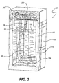
Fig. 2 is a partial perspective view of the heater shown inFig 1 during intermediate filling; -
Fig. 3 is a partial perspective view of the heater shown in Fig-1, when full; -
Fig. 4 is a logic diagram associated with the operating temperature calibration of the heater shown inFig. 1 ; and -
Fig. 5 is a logic diagram associated with the sleep mode of the heater shown inFig. 1 .Fig. 5 and the accompanying description are not part of the claimed invention. - Referring to
Figs. 1 to 3 there is shown an embodiment of a boilingwater heater 10 according to the present invention. Thewater heater 10 has awater tank 12, anouter casing 14 andinsulation 16 therebetween. Inside thewater tank 12, there is anelectric heating element 18, which has a lowercoiled end 18a, and first, second andthird level sensors water heater 10 also includes amounting block 26 for the threelevel sensors - The
heater 10 also has a controller (not shown) which is connected to the threelevel sensors tank 12, a timer and a number of other components. The controller can control the energy supply to theheating coil 18 in response to signals received from the threelevel sensors - The
water heater 10 also includes awater inlet pipe 28 with aninlet elbow 30. Theelbow 30, and thus thepipe 28, is supplied with mains water through a solenoid operated inlet valve (not shown), which is also controlled by the controller. Thewater heater 10 also includes a solenoid operated outlet valve, which is also controlled by the controller, and outlet pipe, which are not shown inFigs. 1 to 3 for clarity purposes. - A method of determining an operating water temperature (ie. calibrating) for the
water heater 10 will now be described in conjunction withFig. 4 which represents thebasic steps - The
first step 40 of the method occurs after theheater 10 has been installed and comprises thetank 12 being filled withwater 32 until the level reaches that of thefirst level sensor 20. This amount of thewater 32 is sufficient to immerse thecoiled end 18a of theheating element 18. - As indicated in
step 42, the controller then energises theheating element 18 to heat the water to 95°C and then, as indicated instep 44, maintain thewater 32 at this temperature for a period of 120 seconds in order to saturate thetank 12 with heat. - As indicated in
step 46, at the end of this saturation period thewater 32 is then heated to boiling point in a 90 second time period and thecontroller 26 records the maximum water temperature reached. It is important to note that theheating element 18 can boil thewater 32 prior to the completion of the 90 second period and that but the temperature of boiling water remains constant until all the water has boiled away. - At the end of the 90 second period the controller recalls the maximum temperature reached, which will be the boiling point for the atmospheric conditions where the
heater 10 has been installed. The controller will then set the operating temperature or set point of thewater heater 10 at 1.5 below the measured boiling point. - When this calibration process has taken place the
water heater 10 will then continue to fill and heat up. More particularly, the controller will open thevalve 32 and fill thetank 12 with water until it reaches the second water level sensor 24 (seeFig. 2 ) and at a controlled rate which will not allow thewater 32 in thetank 12 to drop 2°C below the set point temperature. When thewater 30 reaches the set point temperature theinlet valve 32 opens and allows water to enter thetank 12 until such time as the temperature of the water drops 3°C below the set point. If the water at any time drops to more than 3°C below the set point theinlet valve 30 is closed and theheater 10 allowed to heat up to the set point temperature. During this filling period the controller energises the heating element to operate at 100% power. - There are numerous advantages arising from the above calibration method. Firstly, the performance from one heater to another is always consistent. Secondly, the exact accuracy of the temperature measuring device utilised in the heater is not critical, as long as the device is stable. Thirdly, the performance of the heater relative to actual boiling point is always consistent. Fourthly, the operating water temperature is always maintained extremely close to the actual boiling point as the actual boiling point is firstly determined by the heater. Fifthly, no compromises in performance are required to achieve optimum performance at different sites having different atmospheric conditions. Sixthly, no external adjustment is required to achieve optimum performance and no skilled service technician is required for optimum performance. The above advantages also lead to lower cost to the user, reduced energy consumption as over boil conditions are prevented and overall improved customer satisfaction.
- A method of operating the
water heater 10 in an energy saving or sleep mode will now be described in conjunction withFig. 5 which represents thebasic steps - As indicated in
step 50, during normal operation of thewater heater 10 the controller monitors the length of time since the hot water outlet valve (not shown) has been activated. More particularly, the controller monitors whether the period of valve inactivity is 2 or 4 hours, depending on the setting selected. - As indicated in
step 52, if the hot water outlet valve has not operated for the selected time, then energy is removed from theheating element 18 to place thewater heater 10, to place it in an energy saving mode (sleep mode), until the temperature of the water in thetank 12 has fallen to about 64°C. - As indicated in
step 54, once the water temperature has reached 64°C, power is pulsed to theelement 18 at a rate sufficient to maintain the water temperature at about 64°C. However, and as indicated instep 56, if the hot water outlet valve is activated the sleep mode is cancelled and theelement 18 is energised to bring thewater 32 back up to its operating set point. Typically, thewater 32 will reach the preferred operating temperature within about 2 to 3 minutes. - The advantages of the sleep mode described above are as follows. Firstly, no pre-programmed timer is required. Secondly, no external influence is required. Thirdly, the system is far more flexible for the user. Fourthly, energy savings are achieved with an impact on both energy cost and environmental greenhouse gases reductions. Lastly, health considerations are not compromised as the water is not allowed to cool to a temperature where bacteria growth may occur.
- The
heater 10 also has a general mode of operation which leads to increased energy savings as will be described below. - As stated earlier, when water is brought to boil, the temperature of the water remains constant whilst the water boils. Also, when the controller recognises that a desired temperature has been reached and shuts off power to the element, hysteresis normally causes the residual heat from the element to cause some over boiling and therefore energy wastage. This can be further complicated by the response time lag of the controller.
- In the
heater 10, the controller recognises when the temperature of the water is approaching the predetermined operating temperature and begins to reduce the energy applied to theelement 18. Put another way, the closer thewater 32 is to the boiling temperature the lower the energy input. - More particularly, when the
tank 12 is filled to the second water level sensor 22 (seeFig. 2 ), the controller supplies full power to theelement 18 until thewater 32 in thetank 12 is heated to within 2°C of the set point. At this point the power supplied to theelement 18 is reduced to 50% of its maximum capacity. This prevents theheater 10 from venting excessive steam - Further, when the
tank 12 is filled to the third water level sensor 24 (seeFig. 3 ), the inlet valve is kept open for 20 seconds. This allows a slight overfilling of thetank 12 and prevents nuisance operating of thevalve 32 due to evaporation or water turbulence. Theelement 18 is also set to operate at 25% of its maximum and maintained there until the set point temperature is reached. Finally, when the water temperature is within 0.5°C of the set point the power supplied to theelement 18 is reduced to 10% of its maximum capacity and supplied in pulses to maintain the water temperature at the set point. - The advantages arising from this are as follows. Firstly, the method provides more accurate temperature control at the operating condition. Secondly, the heater has reduced power consumption. The minimising of over boiling results in less steam generation, minimal resource wastage and a quieter running water heater.
- Although the invention has been described with reference to a preferred embodiment, it would be appreciated by those skilled in the art that the invention may be embodied in many other forms, the scope of the invention being described in the accompanying claims.
Claims (6)
- A method of determining an operating water temperature for a boiling water heater (10), the method including the following steps:(a) adding water to a tank (12) to a predetermined level;(b) heating the water in the tank (12);(c) applying sufficient heat to the water in the tank (12) so as to cause boiling of the water in the tank (12) within a predetermined first period of time;(d) measuring the boiling water temperature of the water in the tank (12); and(e) subtracting a predetermined temperature from the boiling water temperature measured in step (d) to arrive at the operating water temperature;characterised in that in step (b) the water is heated to approximately 95 degrees Celsius; and
in that the method further includes the step of maintaining the water in the tank (12) at approximately 95 degrees Celsius for a predetermined second period of time between steps (b) and (c). - The method as claimed in claim 1, wherein the first and second predetermined periods of time are approximately 90 and 120 seconds respectively.
- The method as claimed in claim 1 or 2, wherein the predetermined temperature subtracted in step (e) is 1.5 degrees Celsius.
- A water heater (10) adapted to determine an operating water temperature, the heater (10) including:a water tank (12);means to measure the water temperature of the water in the tank (12);a timer;heating means (18) adapted to heat the water in the tank (12); anda controller adapted to control the heating means (18) in response to input from the timer and the temperature measuring means;wherein the controller is configured to control the heating means (18) to heat the water in the tank (12) to a first temperature and is configured to subsequently control the heating means (18) to apply sufficient heat to the water in the tank (12) so as to cause boiling of the water in the tank (12) within a predetermined first period of time, wherein the operating water temperature of the water is the measured boiling water temperature minus a predetermined temperature;characterised in that the first temperature is approximately 95 degrees Celsius; andin that the controller is configured to control the heating means (18) to maintain the water in the tank (12) at approximately 95 degrees Celsius for a predetermined second period of time, prior to controlling the heating means (18) to apply the sufficient heat to the water in the tank (12) so as to cause the boiling of the water in the tank within the predetermined first period of time.
- The water heater as claimed in claim 4, wherein the first and second predetermined periods of time are approximately 90 and 120 seconds respectively.
- The water heater as claimed in claim 4 or 5, wherein the predetermined temperature subtracted is 1.5 degrees Celsius.
Priority Applications (1)
| Application Number | Priority Date | Filing Date | Title |
|---|---|---|---|
| CY20141100537T CY1115277T1 (en) | 2004-03-15 | 2014-07-17 | WATER HEATER AND METHOD OF OPERATION |
Applications Claiming Priority (2)
| Application Number | Priority Date | Filing Date | Title |
|---|---|---|---|
| AU2004901343A AU2004901343A0 (en) | 2004-03-15 | A Water Heater and a Method of Operating Same | |
| PCT/AU2005/000286 WO2005088205A1 (en) | 2004-03-15 | 2005-03-01 | A water heater and a method of operating same |
Publications (3)
| Publication Number | Publication Date |
|---|---|
| EP1735569A1 EP1735569A1 (en) | 2006-12-27 |
| EP1735569A4 EP1735569A4 (en) | 2009-12-30 |
| EP1735569B1 true EP1735569B1 (en) | 2014-04-23 |
Family
ID=34975684
Family Applications (1)
| Application Number | Title | Priority Date | Filing Date |
|---|---|---|---|
| EP05706320.8A Expired - Lifetime EP1735569B1 (en) | 2004-03-15 | 2005-03-01 | A water heater and a method of operating same |
Country Status (9)
| Country | Link |
|---|---|
| US (1) | US20080257281A1 (en) |
| EP (1) | EP1735569B1 (en) |
| JP (1) | JP2007529708A (en) |
| CN (1) | CN1950647B (en) |
| CA (1) | CA2559306A1 (en) |
| CY (1) | CY1115277T1 (en) |
| NZ (1) | NZ550379A (en) |
| WO (1) | WO2005088205A1 (en) |
| ZA (1) | ZA200608043B (en) |
Families Citing this family (16)
| Publication number | Priority date | Publication date | Assignee | Title |
|---|---|---|---|---|
| AU2008238594B2 (en) * | 2007-04-13 | 2011-04-28 | Rheem Australia Pty Limited | Improvements in water heaters |
| GB0711752D0 (en) * | 2007-06-18 | 2007-07-25 | Otter Controls Ltd | Electrical appliances |
| CN102331089B (en) * | 2011-05-25 | 2013-08-07 | 宁波奥克斯电气有限公司 | Antibacterial treatment method of air source water heater storage water tank |
| CN102322679B (en) * | 2011-06-02 | 2013-07-17 | 宋志辉 | Instant boiling type water boiler |
| TWI526658B (en) * | 2011-11-17 | 2016-03-21 | 財團法人工業技術研究院 | Storage water heater with instant hot water supply and control method thereof |
| NZ629050A (en) * | 2012-02-27 | 2015-02-27 | Zip Ind Aust Pty Ltd | A water heater and a method of operating same |
| TR201601836U1 (en) * | 2013-08-14 | 2018-10-22 | Arzum Elektrikli Ev Aletleri Sanayi Ve Ticaret Anonim Sirketi | A beverage preparation machine. |
| CN104566992B (en) * | 2013-10-09 | 2018-01-12 | 海尔集团公司 | Control method of electric water heater and electric water heater |
| CN104596111B (en) * | 2014-12-15 | 2017-06-23 | 广东盈科电子有限公司 | A kind of water heats boiling point adaptive approach |
| CN106979623B (en) * | 2017-05-17 | 2018-08-21 | 中国人民解放军空军勤务学院 | A kind of oil buring water heating stove security protection and control device and method |
| US10895387B2 (en) * | 2017-11-14 | 2021-01-19 | Rheem Manufacturing Company | Hybrid heat pump water heaters |
| US11350783B2 (en) * | 2018-12-17 | 2022-06-07 | Stiebel Eltron Gmbh & Co. Kg | Hot water dispenser and method for determining a boiling point of water of a hot water dispenser |
| CN111621954A (en) * | 2019-02-12 | 2020-09-04 | 青岛海尔洗衣机有限公司 | Method for calibrating boiling point of washing machine, washing machine and control method of washing machine |
| US11852381B2 (en) * | 2020-04-09 | 2023-12-26 | Eccotemp Systems, LLC | Water heater device and method of use |
| US20230064869A1 (en) * | 2020-04-09 | 2023-03-02 | Eccotemp Systems, LLC | Improved Water Heater Device with TRIAC and Method of Use |
| CN115486710A (en) * | 2022-10-21 | 2022-12-20 | 珠海格力电器股份有限公司 | Method, device, computer equipment and storage medium for determining boiling point temperature of water dispenser |
Family Cites Families (34)
| Publication number | Priority date | Publication date | Assignee | Title |
|---|---|---|---|---|
| NL7111342A (en) * | 1971-08-17 | 1973-02-20 | ||
| US3793934A (en) * | 1972-12-15 | 1974-02-26 | Bunn O Matic Corp | Automatic coffee maker with liquid level sensor and siphon control |
| US4085702A (en) | 1976-03-29 | 1978-04-25 | Eastman Kodak Company | Offset prevention during fixing |
| US4058702A (en) * | 1976-04-26 | 1977-11-15 | Electro-Thermal Corporation | Fluid heating apparatus |
| US4354094A (en) * | 1980-11-12 | 1982-10-12 | Zip Heaters (Aust.) Pty. Limited | Thermostatically controlled electric continuous water heating unit |
| GB2166530A (en) | 1984-11-02 | 1986-05-08 | Ti | Liquid heating systems |
| US4769151A (en) * | 1986-10-30 | 1988-09-06 | Cobe Laboratories, Inc. | Heater control for liquid flowing through a chamber |
| NL8602802A (en) * | 1986-11-05 | 1988-06-01 | Verheijen Bv | DEVICE FOR DELIVERING HOT WATER. |
| NL8701989A (en) * | 1987-08-25 | 1989-03-16 | Stork Research | TRANSFER ROLLERS FOR ELECTROSTATIC TRANSFER OF A DEVELOPER IMAGE AND DEVICE INCLUDING ONE OR MORE OF SUCH TRANSFER ROLLERS. |
| CN88200566U (en) * | 1988-01-26 | 1988-09-28 | 张立夫 | Vapor boiling water stove |
| GB8803079D0 (en) | 1988-02-10 | 1988-03-09 | Hepburn G | Boiler control system |
| GB2234338B (en) | 1988-02-10 | 1992-09-09 | George Hepburn | Electric boiler control system |
| CA2030976C (en) * | 1990-11-28 | 1994-09-20 | Andre Laperriere | Domestic water heater designed to reduce the risks of bacterial contamination |
| AU661557B2 (en) | 1991-12-21 | 1995-07-27 | Imi Waterheating Limited | Waterheater |
| JP2507861B2 (en) * | 1993-09-01 | 1996-06-19 | 細山熱器株式会社 | Boiling detection method for water heater |
| AUPM448394A0 (en) * | 1994-03-15 | 1994-04-14 | Zip Heaters (Australia) Pty Limited | Protection and control of continuous boiling water units |
| CA2151881A1 (en) * | 1995-06-15 | 1996-12-16 | Nazir Dosani | Programmable thermostat to reduce bacterial proliferation to prevent legionellosis |
| CN2230561Y (en) * | 1995-09-12 | 1996-07-10 | 陈水谦 | Microcomputer thermos bottle control structure device |
| CA2198641A1 (en) | 1997-02-27 | 1998-08-27 | Nizar Ladha | Thermal storage controller with auto-power setting |
| JPH10314030A (en) | 1997-05-22 | 1998-12-02 | Matsushita Electric Ind Co Ltd | Electric water heater |
| GB9719482D0 (en) | 1997-09-12 | 1997-11-12 | Redring Electric Ltd | Liquid heating system |
| JP3400332B2 (en) * | 1998-01-20 | 2003-04-28 | 象印マホービン株式会社 | Electric water heater |
| US6282370B1 (en) * | 1998-09-03 | 2001-08-28 | Balboa Instruments, Inc. | Control system for bathers |
| CN2386372Y (en) * | 1998-12-04 | 2000-07-05 | 谢绍浩 | Automatic quick electric water heater with fractional heating |
| JP3683435B2 (en) * | 1999-04-20 | 2005-08-17 | ホシザキ電機株式会社 | Hot water storage device |
| JP3642233B2 (en) * | 1999-08-03 | 2005-04-27 | 松下電器産業株式会社 | Water heater |
| DE10138455A1 (en) * | 2001-08-04 | 2003-02-13 | Braun Gmbh | Method of heating water involves determining water capacity and start temperature to control heating power input |
| CN2525906Y (en) * | 2001-07-20 | 2002-12-18 | 北京中日新自动化系统有限公司 | Digital temp-regulating automatic drinking water apparatus |
| US20040069768A1 (en) * | 2002-10-11 | 2004-04-15 | Patterson Wade C. | System and method for controlling temperature control elements that are used to alter liquid temperature |
| US7804047B2 (en) * | 2003-03-05 | 2010-09-28 | Honeywell International Inc. | Temperature sensor diagnostic for determining water heater health status |
| NZ546849A (en) | 2003-12-23 | 2007-10-26 | Rheem Australia Pty Ltd | A water heater and water sanitizing process |
| US7574120B2 (en) * | 2005-05-11 | 2009-08-11 | A. O. Smith Corporation | System and method for estimating and indicating temperature characteristics of temperature controlled liquids |
| EP2445622B8 (en) * | 2009-10-16 | 2022-07-20 | F'real! Foods, Llc | Sanitation of commercial frozen food preparation apparatus |
| US20100300377A1 (en) * | 2010-08-11 | 2010-12-02 | Buescher Thomas P | Water heater apparatus with differential control |
-
2005
- 2005-03-01 JP JP2007503146A patent/JP2007529708A/en active Pending
- 2005-03-01 WO PCT/AU2005/000286 patent/WO2005088205A1/en not_active Ceased
- 2005-03-01 NZ NZ550379A patent/NZ550379A/en not_active IP Right Cessation
- 2005-03-01 CN CN2005800146799A patent/CN1950647B/en not_active Expired - Fee Related
- 2005-03-01 US US10/592,833 patent/US20080257281A1/en not_active Abandoned
- 2005-03-01 CA CA002559306A patent/CA2559306A1/en not_active Abandoned
- 2005-03-01 EP EP05706320.8A patent/EP1735569B1/en not_active Expired - Lifetime
-
2006
- 2006-09-27 ZA ZA200608043A patent/ZA200608043B/en unknown
-
2014
- 2014-07-17 CY CY20141100537T patent/CY1115277T1/en unknown
Also Published As
| Publication number | Publication date |
|---|---|
| WO2005088205A1 (en) | 2005-09-22 |
| WO2005088205A8 (en) | 2005-11-24 |
| EP1735569A4 (en) | 2009-12-30 |
| EP1735569A1 (en) | 2006-12-27 |
| CN1950647B (en) | 2010-05-05 |
| US20080257281A1 (en) | 2008-10-23 |
| JP2007529708A (en) | 2007-10-25 |
| CN1950647A (en) | 2007-04-18 |
| CA2559306A1 (en) | 2005-09-22 |
| NZ550379A (en) | 2008-11-28 |
| HK1093551A1 (en) | 2007-03-02 |
| CY1115277T1 (en) | 2017-01-04 |
| ZA200608043B (en) | 2008-06-25 |
Similar Documents
| Publication | Publication Date | Title |
|---|---|---|
| EP1735569B1 (en) | A water heater and a method of operating same | |
| US20020088867A1 (en) | Method for controlling a floor heating system | |
| CA2482383A1 (en) | Heater controller and heater control method of refrigerator | |
| AU2013225606B2 (en) | A water heater and a method of operating same | |
| AU2005222440B2 (en) | A water heater and a method of operating same | |
| HK1093551B (en) | A water heater and a method of operating same | |
| AU2008238594B2 (en) | Improvements in water heaters | |
| AU2007231757A1 (en) | A water heater and a method of operating same | |
| JPH1096254A (en) | Sanitary washing equipment | |
| JP2007003023A (en) | Hot water storage water heater | |
| JPH11351662A (en) | Hot water supply device for bathtub | |
| JP2917701B2 (en) | Automatic bath equipment | |
| JP2505641B2 (en) | Hot water supply system | |
| JP2847244B2 (en) | Hot water filling control method and apparatus for automatic bath apparatus with water heater | |
| JP3132790B2 (en) | Automatic bath pot and hot water filling method | |
| JP3566414B2 (en) | Hot water supply device for bathtub | |
| JP2001165459A (en) | Hot water supply system | |
| JPH0615262Y2 (en) | Automatic drainage control device | |
| JP3331166B2 (en) | Water heater | |
| JPH06147643A (en) | Hot-water supplier for bathtub | |
| JPS62258956A (en) | Water heater control device | |
| HK1022965A (en) | A method for the operation of an electric heating apparatus | |
| JP2006153451A (en) | Automatic hot-water filling device | |
| HK1200205B (en) | A water heater and a method of operating same | |
| JPH081331B2 (en) | Bathtub water level detection control device |
Legal Events
| Date | Code | Title | Description |
|---|---|---|---|
| PUAI | Public reference made under article 153(3) epc to a published international application that has entered the european phase |
Free format text: ORIGINAL CODE: 0009012 |
|
| 17P | Request for examination filed |
Effective date: 20061005 |
|
| AK | Designated contracting states |
Kind code of ref document: A1 Designated state(s): AT BE BG CH CY CZ DE DK EE ES FI FR GB GR HU IE IS IT LI LT LU MC NL PL PT RO SE SI SK TR |
|
| REG | Reference to a national code |
Ref country code: HK Ref legal event code: DE Ref document number: 1093551 Country of ref document: HK |
|
| DAX | Request for extension of the european patent (deleted) | ||
| TPAC | Observations filed by third parties |
Free format text: ORIGINAL CODE: EPIDOSNTIPA |
|
| A4 | Supplementary search report drawn up and despatched |
Effective date: 20091126 |
|
| 17Q | First examination report despatched |
Effective date: 20100304 |
|
| REG | Reference to a national code |
Ref country code: DE Ref legal event code: R079 Ref document number: 602005043361 Country of ref document: DE Free format text: PREVIOUS MAIN CLASS: F24H0001180000 Ipc: F24H0009200000 |
|
| GRAP | Despatch of communication of intention to grant a patent |
Free format text: ORIGINAL CODE: EPIDOSNIGR1 |
|
| RIC1 | Information provided on ipc code assigned before grant |
Ipc: F24H 9/20 20060101AFI20131009BHEP |
|
| INTG | Intention to grant announced |
Effective date: 20131105 |
|
| GRAS | Grant fee paid |
Free format text: ORIGINAL CODE: EPIDOSNIGR3 |
|
| GRAA | (expected) grant |
Free format text: ORIGINAL CODE: 0009210 |
|
| AK | Designated contracting states |
Kind code of ref document: B1 Designated state(s): AT BE BG CH CY CZ DE DK EE ES FI FR GB GR HU IE IS IT LI LT LU MC NL PL PT RO SE SI SK TR |
|
| REG | Reference to a national code |
Ref country code: GB Ref legal event code: FG4D |
|
| REG | Reference to a national code |
Ref country code: CH Ref legal event code: EP |
|
| REG | Reference to a national code |
Ref country code: AT Ref legal event code: REF Ref document number: 664091 Country of ref document: AT Kind code of ref document: T Effective date: 20140515 |
|
| REG | Reference to a national code |
Ref country code: IE Ref legal event code: FG4D |
|
| REG | Reference to a national code |
Ref country code: DE Ref legal event code: R096 Ref document number: 602005043361 Country of ref document: DE Effective date: 20140605 |
|
| REG | Reference to a national code |
Ref country code: NL Ref legal event code: T3 |
|
| REG | Reference to a national code |
Ref country code: AT Ref legal event code: MK05 Ref document number: 664091 Country of ref document: AT Kind code of ref document: T Effective date: 20140423 |
|
| REG | Reference to a national code |
Ref country code: LT Ref legal event code: MG4D |
|
| REG | Reference to a national code |
Ref country code: HK Ref legal event code: GR Ref document number: 1093551 Country of ref document: HK |
|
| PG25 | Lapsed in a contracting state [announced via postgrant information from national office to epo] |
Ref country code: IS Free format text: LAPSE BECAUSE OF FAILURE TO SUBMIT A TRANSLATION OF THE DESCRIPTION OR TO PAY THE FEE WITHIN THE PRESCRIBED TIME-LIMIT Effective date: 20140823 Ref country code: FI Free format text: LAPSE BECAUSE OF FAILURE TO SUBMIT A TRANSLATION OF THE DESCRIPTION OR TO PAY THE FEE WITHIN THE PRESCRIBED TIME-LIMIT Effective date: 20140423 Ref country code: LT Free format text: LAPSE BECAUSE OF FAILURE TO SUBMIT A TRANSLATION OF THE DESCRIPTION OR TO PAY THE FEE WITHIN THE PRESCRIBED TIME-LIMIT Effective date: 20140423 Ref country code: BG Free format text: LAPSE BECAUSE OF FAILURE TO SUBMIT A TRANSLATION OF THE DESCRIPTION OR TO PAY THE FEE WITHIN THE PRESCRIBED TIME-LIMIT Effective date: 20140723 Ref country code: GR Free format text: LAPSE BECAUSE OF FAILURE TO SUBMIT A TRANSLATION OF THE DESCRIPTION OR TO PAY THE FEE WITHIN THE PRESCRIBED TIME-LIMIT Effective date: 20140724 |
|
| PG25 | Lapsed in a contracting state [announced via postgrant information from national office to epo] |
Ref country code: AT Free format text: LAPSE BECAUSE OF FAILURE TO SUBMIT A TRANSLATION OF THE DESCRIPTION OR TO PAY THE FEE WITHIN THE PRESCRIBED TIME-LIMIT Effective date: 20140423 Ref country code: SE Free format text: LAPSE BECAUSE OF FAILURE TO SUBMIT A TRANSLATION OF THE DESCRIPTION OR TO PAY THE FEE WITHIN THE PRESCRIBED TIME-LIMIT Effective date: 20140423 Ref country code: ES Free format text: LAPSE BECAUSE OF FAILURE TO SUBMIT A TRANSLATION OF THE DESCRIPTION OR TO PAY THE FEE WITHIN THE PRESCRIBED TIME-LIMIT Effective date: 20140423 Ref country code: PL Free format text: LAPSE BECAUSE OF FAILURE TO SUBMIT A TRANSLATION OF THE DESCRIPTION OR TO PAY THE FEE WITHIN THE PRESCRIBED TIME-LIMIT Effective date: 20140423 |
|
| PG25 | Lapsed in a contracting state [announced via postgrant information from national office to epo] |
Ref country code: PT Free format text: LAPSE BECAUSE OF FAILURE TO SUBMIT A TRANSLATION OF THE DESCRIPTION OR TO PAY THE FEE WITHIN THE PRESCRIBED TIME-LIMIT Effective date: 20140825 |
|
| REG | Reference to a national code |
Ref country code: DE Ref legal event code: R097 Ref document number: 602005043361 Country of ref document: DE |
|
| PG25 | Lapsed in a contracting state [announced via postgrant information from national office to epo] |
Ref country code: BE Free format text: LAPSE BECAUSE OF FAILURE TO SUBMIT A TRANSLATION OF THE DESCRIPTION OR TO PAY THE FEE WITHIN THE PRESCRIBED TIME-LIMIT Effective date: 20140423 Ref country code: RO Free format text: LAPSE BECAUSE OF FAILURE TO SUBMIT A TRANSLATION OF THE DESCRIPTION OR TO PAY THE FEE WITHIN THE PRESCRIBED TIME-LIMIT Effective date: 20140423 Ref country code: SK Free format text: LAPSE BECAUSE OF FAILURE TO SUBMIT A TRANSLATION OF THE DESCRIPTION OR TO PAY THE FEE WITHIN THE PRESCRIBED TIME-LIMIT Effective date: 20140423 Ref country code: EE Free format text: LAPSE BECAUSE OF FAILURE TO SUBMIT A TRANSLATION OF THE DESCRIPTION OR TO PAY THE FEE WITHIN THE PRESCRIBED TIME-LIMIT Effective date: 20140423 Ref country code: DK Free format text: LAPSE BECAUSE OF FAILURE TO SUBMIT A TRANSLATION OF THE DESCRIPTION OR TO PAY THE FEE WITHIN THE PRESCRIBED TIME-LIMIT Effective date: 20140423 Ref country code: CZ Free format text: LAPSE BECAUSE OF FAILURE TO SUBMIT A TRANSLATION OF THE DESCRIPTION OR TO PAY THE FEE WITHIN THE PRESCRIBED TIME-LIMIT Effective date: 20140423 |
|
| PLBE | No opposition filed within time limit |
Free format text: ORIGINAL CODE: 0009261 |
|
| STAA | Information on the status of an ep patent application or granted ep patent |
Free format text: STATUS: NO OPPOSITION FILED WITHIN TIME LIMIT |
|
| 26N | No opposition filed |
Effective date: 20150126 |
|
| REG | Reference to a national code |
Ref country code: DE Ref legal event code: R097 Ref document number: 602005043361 Country of ref document: DE Effective date: 20150126 |
|
| PG25 | Lapsed in a contracting state [announced via postgrant information from national office to epo] |
Ref country code: SI Free format text: LAPSE BECAUSE OF FAILURE TO SUBMIT A TRANSLATION OF THE DESCRIPTION OR TO PAY THE FEE WITHIN THE PRESCRIBED TIME-LIMIT Effective date: 20140423 |
|
| PG25 | Lapsed in a contracting state [announced via postgrant information from national office to epo] |
Ref country code: MC Free format text: LAPSE BECAUSE OF FAILURE TO SUBMIT A TRANSLATION OF THE DESCRIPTION OR TO PAY THE FEE WITHIN THE PRESCRIBED TIME-LIMIT Effective date: 20140423 Ref country code: LU Free format text: LAPSE BECAUSE OF FAILURE TO SUBMIT A TRANSLATION OF THE DESCRIPTION OR TO PAY THE FEE WITHIN THE PRESCRIBED TIME-LIMIT Effective date: 20150301 |
|
| REG | Reference to a national code |
Ref country code: CH Ref legal event code: PL |
|
| REG | Reference to a national code |
Ref country code: FR Ref legal event code: ST Effective date: 20151130 |
|
| PG25 | Lapsed in a contracting state [announced via postgrant information from national office to epo] |
Ref country code: CH Free format text: LAPSE BECAUSE OF NON-PAYMENT OF DUE FEES Effective date: 20150331 Ref country code: LI Free format text: LAPSE BECAUSE OF NON-PAYMENT OF DUE FEES Effective date: 20150331 |
|
| PG25 | Lapsed in a contracting state [announced via postgrant information from national office to epo] |
Ref country code: FR Free format text: LAPSE BECAUSE OF NON-PAYMENT OF DUE FEES Effective date: 20150331 |
|
| PG25 | Lapsed in a contracting state [announced via postgrant information from national office to epo] |
Ref country code: HU Free format text: LAPSE BECAUSE OF FAILURE TO SUBMIT A TRANSLATION OF THE DESCRIPTION OR TO PAY THE FEE WITHIN THE PRESCRIBED TIME-LIMIT; INVALID AB INITIO Effective date: 20050301 |
|
| PG25 | Lapsed in a contracting state [announced via postgrant information from national office to epo] |
Ref country code: TR Free format text: LAPSE BECAUSE OF FAILURE TO SUBMIT A TRANSLATION OF THE DESCRIPTION OR TO PAY THE FEE WITHIN THE PRESCRIBED TIME-LIMIT Effective date: 20140423 |
|
| REG | Reference to a national code |
Ref country code: DE Ref legal event code: R082 Ref document number: 602005043361 Country of ref document: DE Representative=s name: PAGE, WHITE & FARRER GERMANY LLP, DE |
|
| PGFP | Annual fee paid to national office [announced via postgrant information from national office to epo] |
Ref country code: CY Payment date: 20210205 Year of fee payment: 17 |
|
| PG25 | Lapsed in a contracting state [announced via postgrant information from national office to epo] |
Ref country code: CY Free format text: LAPSE BECAUSE OF NON-PAYMENT OF DUE FEES Effective date: 20220301 |
|
| PGFP | Annual fee paid to national office [announced via postgrant information from national office to epo] |
Ref country code: IE Payment date: 20230202 Year of fee payment: 19 |
|
| PGFP | Annual fee paid to national office [announced via postgrant information from national office to epo] |
Ref country code: IT Payment date: 20230323 Year of fee payment: 19 Ref country code: GB Payment date: 20230130 Year of fee payment: 19 Ref country code: DE Payment date: 20230202 Year of fee payment: 19 |
|
| PGFP | Annual fee paid to national office [announced via postgrant information from national office to epo] |
Ref country code: NL Payment date: 20230324 Year of fee payment: 19 |
|
| P01 | Opt-out of the competence of the unified patent court (upc) registered |
Effective date: 20230608 |
|
| REG | Reference to a national code |
Ref country code: DE Ref legal event code: R119 Ref document number: 602005043361 Country of ref document: DE |
|
| REG | Reference to a national code |
Ref country code: NL Ref legal event code: MM Effective date: 20240401 |
|
| GBPC | Gb: european patent ceased through non-payment of renewal fee |
Effective date: 20240301 |
|
| PG25 | Lapsed in a contracting state [announced via postgrant information from national office to epo] |
Ref country code: NL Free format text: LAPSE BECAUSE OF NON-PAYMENT OF DUE FEES Effective date: 20240401 |
|
| PG25 | Lapsed in a contracting state [announced via postgrant information from national office to epo] |
Ref country code: NL Free format text: LAPSE BECAUSE OF NON-PAYMENT OF DUE FEES Effective date: 20240401 |
|
| PG25 | Lapsed in a contracting state [announced via postgrant information from national office to epo] |
Ref country code: DE Free format text: LAPSE BECAUSE OF NON-PAYMENT OF DUE FEES Effective date: 20241001 |
|
| PG25 | Lapsed in a contracting state [announced via postgrant information from national office to epo] |
Ref country code: GB Free format text: LAPSE BECAUSE OF NON-PAYMENT OF DUE FEES Effective date: 20240301 |
|
| PG25 | Lapsed in a contracting state [announced via postgrant information from national office to epo] |
Ref country code: IE Free format text: LAPSE BECAUSE OF NON-PAYMENT OF DUE FEES Effective date: 20240301 |
|
| PG25 | Lapsed in a contracting state [announced via postgrant information from national office to epo] |
Ref country code: IE Free format text: LAPSE BECAUSE OF NON-PAYMENT OF DUE FEES Effective date: 20240301 Ref country code: GB Free format text: LAPSE BECAUSE OF NON-PAYMENT OF DUE FEES Effective date: 20240301 Ref country code: DE Free format text: LAPSE BECAUSE OF NON-PAYMENT OF DUE FEES Effective date: 20241001 |
|
| PG25 | Lapsed in a contracting state [announced via postgrant information from national office to epo] |
Ref country code: IT Free format text: LAPSE BECAUSE OF NON-PAYMENT OF DUE FEES Effective date: 20240301 |