EP1734641A2 - Cooling system for an electrical machine with center rotor cooling ducts - Google Patents
Cooling system for an electrical machine with center rotor cooling ducts Download PDFInfo
- Publication number
- EP1734641A2 EP1734641A2 EP06252967A EP06252967A EP1734641A2 EP 1734641 A2 EP1734641 A2 EP 1734641A2 EP 06252967 A EP06252967 A EP 06252967A EP 06252967 A EP06252967 A EP 06252967A EP 1734641 A2 EP1734641 A2 EP 1734641A2
- Authority
- EP
- European Patent Office
- Prior art keywords
- rotor
- cooling medium
- ducts
- gap
- stator
- Prior art date
- Legal status (The legal status is an assumption and is not a legal conclusion. Google has not performed a legal analysis and makes no representation as to the accuracy of the status listed.)
- Withdrawn
Links
Images


Classifications
-
- H—ELECTRICITY
- H02—GENERATION; CONVERSION OR DISTRIBUTION OF ELECTRIC POWER
- H02K—DYNAMO-ELECTRIC MACHINES
- H02K9/00—Arrangements for cooling or ventilating
-
- H—ELECTRICITY
- H02—GENERATION; CONVERSION OR DISTRIBUTION OF ELECTRIC POWER
- H02K—DYNAMO-ELECTRIC MACHINES
- H02K9/00—Arrangements for cooling or ventilating
- H02K9/08—Arrangements for cooling or ventilating by gaseous cooling medium circulating wholly within the machine casing
Definitions
- the present invention relates to rotating electrical machines and particularly relates to machines having a core cooling ventilation system.
- subslots In rotating electrical machines, e.g. generators, subslots, open at opposite ends of a rotor, typically underlie the field windings of the rotor. Radial cooling slots extend through the windings in communication with the subslots. A cooling medium is supplied and flows from opposite ends of the rotor through the subslots and the radial cooling ducts of the field windings and exits into the gap between the rotor and the stator.
- the cooling medium for example air, is in direct heat exchange relation with the coils of the rotor field windings.
- This type of cooling ventilation system has proven satisfactory particularly for small machines having a limited length, e.g. on the order of less than 200 inches.
- the long rotors limit the flow of the cooling medium through the subslots. That is, the cumulative cross sectional area of the subslots is considerably less than the cumulative cross sectional area of the radial ducts. This causes a large pressure drop at the entrance locations to the radial cooling ducts and insufficient flow of the cooling medium into the middle or intermediate portions of the rotor.
- a rotating electrical machine comprising a rotor having field windings and a stator about the rotor; a cooling system for the machine including a plurality of generally axially extending subslots opening through opposite ends of the rotor and underlying respective portions of the rotor field windings and a plurality of ducts extending through the field windings adjacent opposite end portions of the rotor in communication with the subslots for receiving a cooling medium flowing axially along the subslots and discharging the cooling medium into a gap between the stator and rotor; the stator including cooling medium inlet ducts intermediate opposite end portions of the machine for flowing cooling medium toward the gap and the rotor, the rotor having a plurality of inlet ducts and outlet ducts intermediate opposite end portions of the rotor for flowing the cooling medium received from the intermediate stator ducts inwardly along the intermediate rotor inlet ducts and outwardly along the intermediate rotor outlet
- stator 14 includes a plurality of radially inwardly directed ducts 16 for flowing a cooling medium radially inwardly into the air gap 18 between the stator and rotor. It will be appreciated that the air gap 18 is shown in considerably exaggerated depth not to scale for clarity of this description and that typically the air gap is maintained a minimum depth for purposes of maintaining efficiency of the machine. Also illustrated are end windings 20 for the stator 14.
- rotor 12 includes a plurality of field windings 20 which extend longitudinally along the rotor in slots 22 formed at circumferentially spaced locations about the rotor.
- the field windings are conventional in construction and are maintained in the slots 22 by wedges 24 which are secured to the rotor in grooves 25 formed adjacent the outer circumference of the rotor.
- the field windings through each slot 22 have radially registering cooling holes forming ducts 26 for flowing a cooling medium about the field windings 20.
- the cooling medium is supplied to the ducts 26 through axially extending subslots 28 open at opposite ends of rotor 12.
- stator cooling slots 16 are provided and the cooling medium flowing through slots 16 exit into the air gap 18 similarly as the cooling medium flowing through the slots 26 exits into gap 18.
- the cooling medium in the air gap 18 typically flows through the annular outer ends of the air gap at the ends of the rotor and stator.
- the intermediate portion of the rotor has flow requirements which may not be met by the typical axially inward flows through the subslots 28. As a consequence, significant heat build-up occurs in central portions of the rotors particularly in these longer electrical machines.
- additional cooling flows for the rotor are provided through the stator via an intermediate stator inlet duct 30.
- the central or intermediate portion 32 of the rotor is also provided with radially inward flow ducts 34 having scoops 36 at the surface of the rotor.
- the scoops 36 are illustrated as projecting beyond the peripheral surface of the rotor, the scoops 36 in practice lie below the surface of the rotor.
- the scoops 36 direct the cooling medium supplied to the air gap 18 via intermediate stator inlet duct 36 radially inwardly through the inlet ducts 34.
- the cooling medium flow then feeds a subslot 40 and vents outwardly through radial outwardly directed ducts 38.
- the subslots 40 may also lie in communication with the subslot 28. It will be appreciated that the cooling medium supplied via stator inlet ducts 30 cools intermediate portions of the rotor, particularly those intermediate rotor portions for long electrical machines.
- the cooling air flow from the intermediate stator inlet duct 30 or a series of stator inlet ducts 31 may be received across gap 18 by diagonally directed rotor inlet ducts 40.
- the diagonal ducts 40 through the field windings communicate the cooling medium in the central portion of the machine from the air gap 18 in radially inward and axial directions. Adjacent the bottom of each slot 22, the cooling medium reverses flow direction and flows generally radially and axially outwardly through diagonal outlet ducts 42 which open into air gap 18.
- the diagonal inlet ducts 40 may similarly, as illustrated in Figure 1, have inlet scoops 46 to assist in directing the flow in a radial inward direction.
- diagonally extending inlet ducts 48 through the field windings in the central or intermediate portion of the machine may communicate with an axially extending subslot 50 for flowing the cooling medium generally axially along the rotor underlying the centrally located portions of the field windings.
- the subslots 50 may communicate with radially outwardly directed ducts 26 and with the subslot 28 of the rotor.
- a baffle 54 may be provided in the air gap 18 to separate the cold flow of cooling medium from the stator from the hot flow coming from the rotor ducts into the air gap.
- the baffle 54 may be located on either the rotor or stator.
- the reduction in flow through the subslots reduces the velocity of the flow in the rotor subslots resulting in improved uniform manifold distribution in the radial ducts.
- Lower pressure losses also occur in the subslots with resultant increased efficiency of the machine.
- the flow inlet in the center or intermediate section of the machine reduces the pressure in the rotor/stator gap resulting in additional flow through the stator center section.
Landscapes
- Engineering & Computer Science (AREA)
- Power Engineering (AREA)
- Motor Or Generator Cooling System (AREA)
Abstract
Description
- The present invention relates to rotating electrical machines and particularly relates to machines having a core cooling ventilation system.
- In rotating electrical machines, e.g. generators, subslots, open at opposite ends of a rotor, typically underlie the field windings of the rotor. Radial cooling slots extend through the windings in communication with the subslots. A cooling medium is supplied and flows from opposite ends of the rotor through the subslots and the radial cooling ducts of the field windings and exits into the gap between the rotor and the stator. Thus the cooling medium, for example air, is in direct heat exchange relation with the coils of the rotor field windings.
- This type of cooling ventilation system has proven satisfactory particularly for small machines having a limited length, e.g. on the order of less than 200 inches. For larger machines, for example rotors in excess of 200 inches, the long rotors limit the flow of the cooling medium through the subslots. That is, the cumulative cross sectional area of the subslots is considerably less than the cumulative cross sectional area of the radial ducts. This causes a large pressure drop at the entrance locations to the radial cooling ducts and insufficient flow of the cooling medium into the middle or intermediate portions of the rotor.
- Various arrangements have been proposed and constructed to provide additional cooling to the intermediate portions of the rotors in these longer rotating machines. For example, scoops at the inlet holes have been used to force the cooling medium into the windings by impact between the cooling medium and the rotating rotor. Diagonal cooling medium flow ducts have also been utilized where the cooling medium flows inwardly to the bottom of the coils through holes slightly axially offset in successive turns and is allowed to return through other similarly axially offset holes to the rotor surface and gap.
- Reverse flow ventilation systems have also been utilized such as disclosed in
U.S. patent No. 5,652,469 . However, there remains a need for providing improved cooling and ventilation particularly in intermediate regions of the rotor in longer electrical machines. - In a preferred embodiment of the present invention there is provided a rotating electrical machine comprising a rotor having field windings and a stator about the rotor; a cooling system for the machine including a plurality of generally axially extending subslots opening through opposite ends of the rotor and underlying respective portions of the rotor field windings and a plurality of ducts extending through the field windings adjacent opposite end portions of the rotor in communication with the subslots for receiving a cooling medium flowing axially along the subslots and discharging the cooling medium into a gap between the stator and rotor; the stator including cooling medium inlet ducts intermediate opposite end portions of the machine for flowing cooling medium toward the gap and the rotor, the rotor having a plurality of inlet ducts and outlet ducts intermediate opposite end portions of the rotor for flowing the cooling medium received from the intermediate stator ducts inwardly along the intermediate rotor inlet ducts and outwardly along the intermediate rotor outlet ducts into the gap.
- The invention will now be described in greater detail, by way of example, with reference to the drawings, in which:-
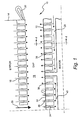
- FIGURE 1 is a schematic illustration of one half of an electrical machine comprised of a stator and a rotor with the drawing figure illustrating various flows of the cooling medium through the machine;
- FIGURE 2 is similar to Figure 1 illustrating a diagonal flow intermediate cooling system;
- FIGURE 3 is a view similar to Figure 1 illustrating a further embodiment of the present invention;
- FIGURE 4 is a cross sectional view taken generally about on line 4-4 in Figure 1; and
- FIGURE 5 is a schematic cross sectional view taken generally about on line 5-5 in Figure 2.
- Referring to the drawings, particularly to Figure 1, there is illustrated an electrical machine generally designated 10 including a
rotor 12 and astator 14. The illustration depicts one end and a portion of the center of the machine, the opposite end being similar. As illustrated,stator 14 includes a plurality of radially inwardly directedducts 16 for flowing a cooling medium radially inwardly into theair gap 18 between the stator and rotor. It will be appreciated that theair gap 18 is shown in considerably exaggerated depth not to scale for clarity of this description and that typically the air gap is maintained a minimum depth for purposes of maintaining efficiency of the machine. Also illustrated areend windings 20 for thestator 14. - As illustrated in Figures 1 and 4,
rotor 12 includes a plurality offield windings 20 which extend longitudinally along the rotor inslots 22 formed at circumferentially spaced locations about the rotor. The field windings are conventional in construction and are maintained in theslots 22 bywedges 24 which are secured to the rotor ingrooves 25 formed adjacent the outer circumference of the rotor. The field windings through eachslot 22 have radially registering coolingholes forming ducts 26 for flowing a cooling medium about thefield windings 20. The cooling medium is supplied to theducts 26 through axially extendingsubslots 28 open at opposite ends ofrotor 12. - As also illustrated in Figure 1,
stator cooling slots 16 are provided and the cooling medium flowing throughslots 16 exit into theair gap 18 similarly as the cooling medium flowing through theslots 26 exits intogap 18. The cooling medium in theair gap 18 typically flows through the annular outer ends of the air gap at the ends of the rotor and stator. - For long rotors, however, the intermediate portion of the rotor has flow requirements which may not be met by the typical axially inward flows through the
subslots 28. As a consequence, significant heat build-up occurs in central portions of the rotors particularly in these longer electrical machines. To provide for additional cooling flows in the central or intermediate portions of these long electrical machines, and in one embodiment of the present invention, additional cooling flows for the rotor are provided through the stator via an intermediate stator inlet duct 30. The central orintermediate portion 32 of the rotor is also provided with radiallyinward flow ducts 34 havingscoops 36 at the surface of the rotor. While thescoops 36 are illustrated as projecting beyond the peripheral surface of the rotor, thescoops 36 in practice lie below the surface of the rotor. Thescoops 36 direct the cooling medium supplied to theair gap 18 via intermediatestator inlet duct 36 radially inwardly through theinlet ducts 34. The cooling medium flow then feeds asubslot 40 and vents outwardly through radial outwardly directedducts 38. Thesubslots 40 may also lie in communication with thesubslot 28. It will be appreciated that the cooling medium supplied via stator inlet ducts 30 cools intermediate portions of the rotor, particularly those intermediate rotor portions for long electrical machines. - Referring to Figure 2, the cooling air flow from the intermediate stator inlet duct 30 or a series of
stator inlet ducts 31 may be received acrossgap 18 by diagonally directedrotor inlet ducts 40. Referring to Figures 2 and 5, thediagonal ducts 40 through the field windings communicate the cooling medium in the central portion of the machine from theair gap 18 in radially inward and axial directions. Adjacent the bottom of eachslot 22, the cooling medium reverses flow direction and flows generally radially and axially outwardly throughdiagonal outlet ducts 42 which open intoair gap 18. Thediagonal inlet ducts 40 may similarly, as illustrated in Figure 1, have inletscoops 46 to assist in directing the flow in a radial inward direction. - Alternatively as illustrated in Figure 3, diagonally extending
inlet ducts 48 through the field windings in the central or intermediate portion of the machine may communicate with an axially extendingsubslot 50 for flowing the cooling medium generally axially along the rotor underlying the centrally located portions of the field windings. Thesubslots 50 may communicate with radially outwardly directedducts 26 and with thesubslot 28 of the rotor. In each of these embodiments of Figures 1-3, a baffle 54 may be provided in theair gap 18 to separate the cold flow of cooling medium from the stator from the hot flow coming from the rotor ducts into the air gap. The baffle 54 may be located on either the rotor or stator. - It will be appreciated that by providing a cooling medium directly through a stator inlet duct adjacent the central or intermediate portion of the electrical machine, additional cooling medium may be supplied to the central or intermediate portion of the rotor. The scoops on the rotor provide extra flow and impart a velocity to the additional cooling flow to permit that flow to flow radially inwardly as the rotor is rotating. The rotational velocity of the rotor, of course, assists the outflow of the additional cooling medium from the bottom of the field winding slots or the subslots. As a consequence, the central or intermediate portions of the rotor may be cooled without increasing the typical subslot ventilation cross-sectional area. Moreover the reduction in flow through the subslots reduces the velocity of the flow in the rotor subslots resulting in improved uniform manifold distribution in the radial ducts. Lower pressure losses also occur in the subslots with resultant increased efficiency of the machine. Further, the flow inlet in the center or intermediate section of the machine reduces the pressure in the rotor/stator gap resulting in additional flow through the stator center section.
Claims (10)
- A rotating electrical machine comprising:a rotor (12) having field windings and a stator (14) about said rotor;a cooling system for the machine including a plurality of generally axially extending subslots (28) opening through opposite ends of the rotor and underlying respective portions of the rotor field windings and a plurality of ducts (26) extending through the field windings adjacent opposite end portions of the rotor in communication with the subslots for receiving a cooling medium flowing axially along said subslots and discharging the cooling medium into a gap (18) between the stator and rotor;said stator including cooling medium inlet ducts (16) intermediate opposite end portions of the machine for flowing cooling medium toward said gap and said rotor, said rotor having a plurality of inlet ducts (26, 34) and outlet ducts (38) intermediate opposite end portions of the rotor for flowing the cooling medium received from said intermediate stator ducts inwardly along said intermediate rotor inlet ducts and outwardly along said intermediate rotor outlet ducts into the gap.
- A machine according to claim 1 wherein said intermediate rotor inlet ducts have scoops (36) at radial outer ends for collecting the cooling medium in the gap received from the stator intermediate cooling medium inlet ducts and flowing the cooling medium inwardly of the rotor.
- A machine according to claim 1 or 2 including a baffle (54) between the cooling medium discharged into the gap from said end rotor ducts and the cooling medium discharged into the gap from said intermediate rotor outlet ducts.
- A machine according to claim 1, 2 or 3 wherein said rotor includes a plurality of subslots (40) located intermediate opposite end portions of the rotor in communication with the intermediate rotor inlet ducts (16) for flowing the cooling medium received therefrom into the intermediate rotor outlet ducts.
- A machine according to any preceding claim wherein said intermediate rotor inlet ducts (48) and said intermediate rotor outlet ducts (42) are disposed at angles to radii of said rotor.
- A machine according to claim 5 wherein said intermediate rotor inlet ducts have scoops (36) at radial outer ends for collecting the cooling medium in the gap received from the stator intermediate cooling medium inlet ducts and flowing the cooling medium inwardly of the rotor.
- A machine according to claim 5 including a baffle (54) between the cooling medium discharged into the gap from said end rotor ducts and the cooling medium discharged into the gap from said intermediate rotor outlet ducts.
- A machine according to claim 1 wherein said intermediate rotor inlet ducts (48) extend at angles to radii of the rotor and said intermediate outlet ducts (38) extend radially of the rotor.
- A machine according to claim 8 wherein the intermediate rotor inlet ducts (48) lie in communication with axially extending subslots lying in communication with said intermediate outlet ducts (38).
- A machine according to claim 8 wherein said intermediate rotor inlet ducts have scoops (46) at radial outer ends for collecting the cooling medium in the gap (18) received from the stator intermediate cooling medium inlet ducts and flowing the cooling medium inwardly of the rotor.
Applications Claiming Priority (1)
| Application Number | Priority Date | Filing Date | Title |
|---|---|---|---|
| US11/150,270 US7462962B2 (en) | 2005-06-13 | 2005-06-13 | Cooling system for an electrical machine with center rotor cooling dusts |
Publications (2)
| Publication Number | Publication Date |
|---|---|
| EP1734641A2 true EP1734641A2 (en) | 2006-12-20 |
| EP1734641A3 EP1734641A3 (en) | 2007-09-12 |
Family
ID=36739925
Family Applications (1)
| Application Number | Title | Priority Date | Filing Date |
|---|---|---|---|
| EP06252967A Withdrawn EP1734641A3 (en) | 2005-06-13 | 2006-06-08 | Cooling system for an electrical machine with center rotor cooling ducts |
Country Status (4)
| Country | Link |
|---|---|
| US (1) | US7462962B2 (en) |
| EP (1) | EP1734641A3 (en) |
| JP (1) | JP2006353086A (en) |
| CN (1) | CN1881749A (en) |
Cited By (1)
| Publication number | Priority date | Publication date | Assignee | Title |
|---|---|---|---|---|
| EP2860852A1 (en) * | 2013-10-14 | 2015-04-15 | Siemens Aktiengesellschaft | Device for deflecting at least one portion of a cooling fluid flowing axially in a space between a rotor and a stator of a rotating electric machine |
Families Citing this family (26)
| Publication number | Priority date | Publication date | Assignee | Title |
|---|---|---|---|---|
| CN101123380B (en) * | 2007-05-25 | 2010-10-27 | 中国科学院电工研究所 | Turbine Generator with Air Cooled Rotor and Evaporatively Cooled Stator |
| JP4486114B2 (en) * | 2007-09-03 | 2010-06-23 | 株式会社日立製作所 | Rotating electric machine |
| JP2010104202A (en) * | 2008-10-27 | 2010-05-06 | Toshiba Corp | Rotor of rotating electrical machine |
| US7893576B2 (en) * | 2009-05-05 | 2011-02-22 | General Electric Company | Generator coil cooling baffles |
| US8450890B2 (en) * | 2009-11-30 | 2013-05-28 | Remy Technologies, L.L.C. | Rotating directional coolant spray for electric machine |
| US8456046B2 (en) * | 2010-06-08 | 2013-06-04 | Remy Technologies, Llc | Gravity fed oil cooling for an electric machine |
| US8519581B2 (en) * | 2010-06-08 | 2013-08-27 | Remy Technologies, Llc | Electric machine cooling system and method |
| US8269383B2 (en) * | 2010-06-08 | 2012-09-18 | Remy Technologies, Llc | Electric machine cooling system and method |
| CN102064636B (en) * | 2011-01-12 | 2012-07-25 | 哈尔滨理工大学 | Steam turbine generator with stator multiloop reciprocating ventilation system |
| EP2512009A1 (en) | 2011-04-15 | 2012-10-17 | Siemens Aktiengesellschaft | Cooling device for cooling a coil braid of an electric machine and method for retrofitting the electric machine with the cooling device |
| US9373984B2 (en) | 2011-06-29 | 2016-06-21 | General Electric Company | Electrical machine |
| CN103138488A (en) * | 2011-11-24 | 2013-06-05 | 苏州贝得科技有限公司 | Composite cooling system of three-phase asynchronous motor for semi-hermetic refrigeration compressor |
| CN107659039A (en) * | 2011-11-25 | 2018-02-02 | 黄得锋 | A kind of full self-cooled machine |
| JP5785521B2 (en) * | 2012-05-10 | 2015-09-30 | 東芝三菱電機産業システム株式会社 | Rotating electric machine |
| US9831746B2 (en) | 2014-10-28 | 2017-11-28 | Ingersoll-Rand Company | Cooling system for electric rotor machine with symmetrical stator passages |
| CN104362790B (en) * | 2014-12-08 | 2016-11-30 | 南阳防爆集团股份有限公司 | A kind of 2 pole box type electric generators |
| US10483812B2 (en) | 2014-12-31 | 2019-11-19 | Ingersoll-Rand Company | Electrical machine and method of manufacture |
| DE102016216245A1 (en) | 2016-08-30 | 2018-03-01 | Zf Friedrichshafen Ag | Arrangement for fluid temperature control |
| DK201600628A1 (en) * | 2016-10-16 | 2018-05-07 | Belt Electric | Rotating electrical machine with air cooling of the stator foil coils. |
| US10326335B2 (en) | 2016-10-20 | 2019-06-18 | General Electric Technology Gmbh | Radial counter flow jet cooling system |
| US10415834B2 (en) | 2016-10-26 | 2019-09-17 | General Electric Technology Gmbh | Tempering air system for gas turbine selective catalyst reduction system |
| CN107508415B (en) * | 2017-09-11 | 2020-01-10 | 珠海格力电器股份有限公司 | Electric machine |
| JP6982522B2 (en) * | 2018-03-08 | 2021-12-17 | 三菱重工業株式会社 | Stator for superconducting rotary machine and superconducting rotary machine |
| CN108566001B (en) * | 2018-06-13 | 2019-06-11 | 哈尔滨理工大学 | A forced-press-extraction type turbo-generator ventilation and cooling system with multi-air paths interwoven |
| EP4106152A1 (en) | 2021-06-17 | 2022-12-21 | General Electric Company | Magnetic mass for a rotor, associated rotor and rotating electric machine |
| CN117439293A (en) * | 2023-10-30 | 2024-01-23 | 珠海凌达压缩机有限公司 | Motor components and scroll compressors |
Family Cites Families (9)
| Publication number | Priority date | Publication date | Assignee | Title |
|---|---|---|---|---|
| US2986664A (en) * | 1959-11-23 | 1961-05-30 | Gen Electric | Diagonal flow direct-cooled dynamoelectric machine rotor |
| US3440462A (en) * | 1966-03-03 | 1969-04-22 | Gen Electric | Dynamoelectric machine gap pick rotor wedges |
| JPS4839881B1 (en) * | 1970-05-11 | 1973-11-27 | ||
| US3995180A (en) * | 1975-03-10 | 1976-11-30 | General Electric Company | Generator rotor outlets for increased ventilation |
| JPS54115708A (en) * | 1978-03-01 | 1979-09-08 | Hitachi Ltd | Revolving electrical machinery |
| DE3408986A1 (en) * | 1984-03-12 | 1985-09-19 | Siemens AG, 1000 Berlin und 8000 München | RUNNER OF AN ELECTRICAL MACHINE WITH AXIAL AND RADIAL COOLING CHANNELS |
| US5652469A (en) | 1994-06-16 | 1997-07-29 | General Electric Company | Reverse flow ventilation system with stator core center discharge duct and/or end region cooling system |
| US5633543A (en) * | 1994-12-12 | 1997-05-27 | General Electric Co. | Pressure equalizer and method for reverse flow ventilated armature in power generator |
| US6316852B1 (en) * | 1999-04-28 | 2001-11-13 | Hitachi, Ltd. | Rotating machine |
-
2005
- 2005-06-13 US US11/150,270 patent/US7462962B2/en not_active Expired - Fee Related
-
2006
- 2006-06-08 EP EP06252967A patent/EP1734641A3/en not_active Withdrawn
- 2006-06-09 JP JP2006160364A patent/JP2006353086A/en not_active Withdrawn
- 2006-06-13 CN CNA2006100958054A patent/CN1881749A/en active Pending
Cited By (3)
| Publication number | Priority date | Publication date | Assignee | Title |
|---|---|---|---|---|
| EP2860852A1 (en) * | 2013-10-14 | 2015-04-15 | Siemens Aktiengesellschaft | Device for deflecting at least one portion of a cooling fluid flowing axially in a space between a rotor and a stator of a rotating electric machine |
| WO2015055355A1 (en) * | 2013-10-14 | 2015-04-23 | Siemens Aktiengesellschaft | Device for deflecting at least a portion of a cooling fluid flowing axially in an intermediate space which is arranged between a rotor and a stator of a rotating electrical machine |
| US10199903B2 (en) | 2013-10-14 | 2019-02-05 | Siemens Aktiengesellschaft | Device for deflecting at least a portion of a cooling fluid lowing axially in an intermediate space which is arranged between a rotor and a stator of a rotating electrical machine |
Also Published As
| Publication number | Publication date |
|---|---|
| US7462962B2 (en) | 2008-12-09 |
| EP1734641A3 (en) | 2007-09-12 |
| CN1881749A (en) | 2006-12-20 |
| US20060279145A1 (en) | 2006-12-14 |
| JP2006353086A (en) | 2006-12-28 |
Similar Documents
| Publication | Publication Date | Title |
|---|---|---|
| EP1734641A2 (en) | Cooling system for an electrical machine with center rotor cooling ducts | |
| US6204580B1 (en) | Direct gas cooled rotor endwinding ventilation schemes for rotating machines with concentric coil rotors | |
| EP1171937B1 (en) | Direct gas cooled longitudinal/cross-flow endwinding ventilation schemes for machines with concentric coil rotors | |
| EP1976095B1 (en) | Rotating electric machine and rotor thereof | |
| KR101223072B1 (en) | Electric machine with air cooling system | |
| US8487490B2 (en) | Electric rotating machine | |
| US9660505B2 (en) | Electrical machine with reduced windage loss | |
| KR101757285B1 (en) | Rotating directional coolant spray for electric machine | |
| US6956313B2 (en) | Method and apparatus for reducing hot spot temperatures on stacked field windings | |
| US20090230790A1 (en) | Electrical machine with an internally cooled rotor | |
| US20240333051A1 (en) | Stator cooling ducts having forced vortexes | |
| EP3654500B1 (en) | Apparatus and method for cooling endwindings in a rotating electric machine | |
| EP3070816B1 (en) | Method and assembly for cooling an electric machine | |
| WO2015086637A1 (en) | An electric machine | |
| US12368332B2 (en) | Integrated stator cooling jacket system | |
| US6759770B1 (en) | Cooling system for modular field windings of a generator | |
| US6426574B1 (en) | Rotor of a turbogenerator having direct gas cooling incorporating a two-stage flow cascade | |
| EP2642406A1 (en) | Ventilation system for an electric machine (variants) | |
| CA1211146A (en) | Fan diffuser and collector combination for cooling systems in dynamoelectric machines | |
| JPH11150898A (en) | Rotating electric machine rotor | |
| JP2009296872A (en) | Heat transfer enhancement of ventilation chimney for electric machine rotor |
Legal Events
| Date | Code | Title | Description |
|---|---|---|---|
| PUAI | Public reference made under article 153(3) epc to a published international application that has entered the european phase |
Free format text: ORIGINAL CODE: 0009012 |
|
| AK | Designated contracting states |
Kind code of ref document: A2 Designated state(s): AT BE BG CH CY CZ DE DK EE ES FI FR GB GR HU IE IS IT LI LT LU LV MC NL PL PT RO SE SI SK TR |
|
| AX | Request for extension of the european patent |
Extension state: AL BA HR MK YU |
|
| RAP1 | Party data changed (applicant data changed or rights of an application transferred) |
Owner name: GENERAL ELECTRIC COMPANY |
|
| PUAL | Search report despatched |
Free format text: ORIGINAL CODE: 0009013 |
|
| AK | Designated contracting states |
Kind code of ref document: A3 Designated state(s): AT BE BG CH CY CZ DE DK EE ES FI FR GB GR HU IE IS IT LI LT LU LV MC NL PL PT RO SE SI SK TR |
|
| AX | Request for extension of the european patent |
Extension state: AL BA HR MK YU |
|
| RIC1 | Information provided on ipc code assigned before grant |
Ipc: H02K 9/08 20060101ALN20070807BHEP Ipc: H02K 1/20 20060101ALN20070807BHEP Ipc: H02K 1/32 20060101ALI20070807BHEP Ipc: H02K 9/00 20060101AFI20070807BHEP |
|
| 17P | Request for examination filed |
Effective date: 20080312 |
|
| AKX | Designation fees paid |
Designated state(s): CH DE GB LI |
|
| 17Q | First examination report despatched |
Effective date: 20080423 |
|
| STAA | Information on the status of an ep patent application or granted ep patent |
Free format text: STATUS: THE APPLICATION IS DEEMED TO BE WITHDRAWN |
|
| 18D | Application deemed to be withdrawn |
Effective date: 20100105 |