EP1734636A2 - Switchbox - Google Patents
Switchbox Download PDFInfo
- Publication number
- EP1734636A2 EP1734636A2 EP06405260A EP06405260A EP1734636A2 EP 1734636 A2 EP1734636 A2 EP 1734636A2 EP 06405260 A EP06405260 A EP 06405260A EP 06405260 A EP06405260 A EP 06405260A EP 1734636 A2 EP1734636 A2 EP 1734636A2
- Authority
- EP
- European Patent Office
- Prior art keywords
- switching
- installation
- communication module
- home
- electrical
- Prior art date
- Legal status (The legal status is an assumption and is not a legal conclusion. Google has not performed a legal analysis and makes no representation as to the accuracy of the status listed.)
- Granted
Links
Images

Classifications
-
- H—ELECTRICITY
- H05—ELECTRIC TECHNIQUES NOT OTHERWISE PROVIDED FOR
- H05B—ELECTRIC HEATING; ELECTRIC LIGHT SOURCES NOT OTHERWISE PROVIDED FOR; CIRCUIT ARRANGEMENTS FOR ELECTRIC LIGHT SOURCES, IN GENERAL
- H05B47/00—Circuit arrangements for operating light sources in general, i.e. where the type of light source is not relevant
- H05B47/10—Controlling the light source
- H05B47/175—Controlling the light source by remote control
- H05B47/19—Controlling the light source by remote control via wireless transmission
- H05B47/195—Controlling the light source by remote control via wireless transmission the transmission using visible or infrared light
-
- H—ELECTRICITY
- H02—GENERATION; CONVERSION OR DISTRIBUTION OF ELECTRIC POWER
- H02J—CIRCUIT ARRANGEMENTS OR SYSTEMS FOR SUPPLYING OR DISTRIBUTING ELECTRIC POWER; SYSTEMS FOR STORING ELECTRIC ENERGY
- H02J13/00—Circuit arrangements for providing remote indication of network conditions, e.g. an instantaneous record of the open or closed condition of each circuitbreaker in the network; Circuit arrangements for providing remote control of switching means in a power distribution network, e.g. switching in and out of current consumers by using a pulse code signal carried by the network
- H02J13/00006—Circuit arrangements for providing remote indication of network conditions, e.g. an instantaneous record of the open or closed condition of each circuitbreaker in the network; Circuit arrangements for providing remote control of switching means in a power distribution network, e.g. switching in and out of current consumers by using a pulse code signal carried by the network characterised by information or instructions transport means between the monitoring, controlling or managing units and monitored, controlled or operated power network element or electrical equipment
- H02J13/00007—Circuit arrangements for providing remote indication of network conditions, e.g. an instantaneous record of the open or closed condition of each circuitbreaker in the network; Circuit arrangements for providing remote control of switching means in a power distribution network, e.g. switching in and out of current consumers by using a pulse code signal carried by the network characterised by information or instructions transport means between the monitoring, controlling or managing units and monitored, controlled or operated power network element or electrical equipment using the power network as support for the transmission
Definitions
- the switch box is designed as a ready-to-install, compact, electrical component and installable at any location within the circuit, but advantageously in or instead of commonly used in conventional installations branch or flush box and thus not visible from the outside.
- the bidirectional communication module sends data describing the current state to the home or building automation control, so that they can perform a data synchronization and note the new switching state. This process is particularly important when a switching command from a push-button or a commander, which is not the home or building automation control, was sent by signal.
- a current state detection is ensured by a so-called "polling". That the communication module sends signals at regular intervals about the current state of one or more consumers to the home or building automation control, which in turn detects and processes state changes via data synchronization.
- Fig. 2 shows an inventive installation 10 with a switch box 24, which is installed instead of a junction box 22.
- the socket 24 includes a radio communication module, short radio module 26, a microcontroller 28 with appropriate software and a switching element 30, the circuit 16, 18, 20 with the electrical load 12 can close.
- the switch box 24 can receive instructions from a home or building automation controller 32, which is also equipped with a radio module 26, to close the circuit 16, 18, 20 and execute it via the switching element 30.
- the switch box 24 can detect the switching movements of the operating element 14 with the microcontroller 28, execute it via the switching element 30 and communicate it via the radio module 26 to the home or building automation controller 32.
- Fig. 3 shows an installation 10, as it occurs in rooms with two or more doors: Here is usually in the vicinity of each door ever a control element 14 'installed. Also in this case, the switch box 24 is used by being used as described in Fig. 2 instead of a simple junction box 22.
- Fig. 4 For larger user zones, installations 10 are typically used as shown in Fig. 4 with controls 14 "comprising more than two individual switches.” Such controls 14 "may also be used in combination with controls 14 'and / or controls not shown, as shown in the drawing 14 are used. Also in these cases, the switch box 24 as shown in FIG. 2 and 3 is used.
- Fig. 5 shows an installation 10, in place of controls 14, 14 ', 14 "monostable push-button 36 in combination with a so-called Minuterie (Timer) 38 is used.
- installation 10 a minute 38 is taken out of service, the functionality is then taken over by the home or building automation controller 32.
- the used switch box 24 as shown in FIG. 2-4 is used.
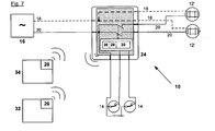
- FIG. 7 shows an installation 10 with two consumers 12 or with two roller shutter motors 12 ', which can also be used as sun blind motors.
- the control of the various consumers 12, 12 'in turn by a switching element 30, which can switch in this case, multiple consumers 12, 12'.
- the switch box 24 receives the necessary switching commands as described via the switch 14, and / or as described radio and / or infrared based by a remote control 34, and / or the home or building automation controller 32.
- the home coordinates or building automation controller 32 in turn set and actual states of the consumers 12, 12 'and performs the function of a control center.
Abstract
Description
Die Erfindung bezieht sich auf eine Installation zur Betätigung von wenigstens einem elektrischen Verbraucher einer Heim- oder Gebäudetechnik, bestehend aus wenigstens je einer Leistungszuführung, einem elektrischen Verbraucher, einem Schaltkreis, einer Schaltdose, einem Bedienelement und einer Heim- oder Gebäudeautomationssteuerung. Weiter betrifft die Erfindung ein Verfahren zum Betrieb der Installation.The invention relates to an installation for operating at least one electrical consumer of a home or building technology, comprising at least one power supply, an electrical load, a circuit, a socket, a control element and a home or building automation control. Furthermore, the invention relates to a method for operating the installation.
Für das Ein- und Ausschalten der elektrischen Verbraucher in Gebäuden sind zahlreiche Ausführungsformen der Verkabelung und der Bedienung auf dem Markt. Üblicherweise werden an einem oder mehreren gut zugänglichen Orten Bedienelemente wie beispielsweise Kippschalter, Ein-/Aus-Druckschalter oder monostabile Taster montiert, die mit einer geeigneten Verkabelung dafür sorgen, dass Stromkreise geöffnet und geschlossen werden können, z.B. zum Ein- und Ausschalten einer Beleuchtung. Zur Vereinfachung und Systematisierung werden zweckmässig in Deckennähe Abzweig- oder Unterputzdosen angebracht. Von den Bedienelementen zu den Abzweig- oder Unterputzdosen und von den Abzweig- oder Unterputzdosen zu den elektrischen Verbrauchern führen in der Regel Stichleitungen. Diese Installationstechnik ist bewährt, bedingt aber einen recht grossen Verkabelungsaufwand.For the switching on and off of the electrical consumers in buildings numerous embodiments of the wiring and the operation in the market. Typically, controls such as toggle switches, on / off pushbuttons, or monostable pushbuttons are mounted in one or more readily accessible locations, which provide suitable cabling to allow circuits to be opened and closed, e.g. for switching on and off a lighting. For simplification and systematization, branched or flush-mounted boxes are expediently mounted near the ceiling. From the control elements to the branch or flush-mounted boxes and from the branch or flush-mounted boxes to the electrical consumers usually lead stub lines. This installation technique is proven, but requires quite a lot of cabling.
Sollen diese elektrischen Verbraucher im Zusammenhang mit einer Gebäudeautomation automatisch angesteuert werden, werden nach dem Stand der Technik ein einzelner Taster und die Leistungszuführung an die Verbraucher mit einem zweiten, separat geführten Kabel einer einheitlichen Gebäudekommunikation zugeführt. Diese Lösung mit einem Gebäudebus zeichnet sich durch eine einheitliche, oftmals auch stockwerkübergreifende Konzeption aus und wird in verschiedenen Ausführungsformen angeboten (z.B. EIB/Konnex, LON). Die einzelnen Knoten (Schalter, Sensoren usw.) enthalten eine gewisse eigene, dezentrale Intelligenz, was zu einer auch für komplexe Anlagen hohen Ausfallsicherheit führt. Auch wegen der zusätzlichen Verkabelung und des Parametrierungs- und Programmieraufwandes hat sich diese Lösung aber nur für Zweckgebäude und bei Wohnneubauten im hohen Preissegment durchgesetzt.If these electrical loads are automatically controlled in connection with a building automation, according to the prior art, a single button and the power supply to the consumer with a second, separately led cable of a uniform building communication supplied. This solution with a building bus is characterized by a uniform, often cross-floor conception and is offered in various embodiments (eg EIB / Konnex, LON). The individual nodes (switches, sensors, etc.) contain a certain amount own, decentralized intelligence, which leads to high reliability even for complex systems. Also because of the additional wiring and the parameterization and programming effort, this solution has prevailed but only for utility buildings and residential new buildings in the high price segment.
Alternativ wurden in den letzten Jahren, nicht zuletzt zur Senkung des Installationsaufwands, verschiedene funkbasierte Lösungen angeboten. Hierzu werden die bestehenden Taster durch Funktaster ersetzt, die in unterschiedlichen Ausführungsformen erhältlich sind:
- In einer ersten Ausführungsform meldet ein Funktaster, statt einen Stromkreis direkt zu schliessen, mit einem Funksender eine Information an einen Funkempfänger, der seinerseits den Stromkreis schliesst. Hierzu muss die bestehende Verkabelung abgeändert und ein zusätzlicher Funkempfänger in einen umgebauten Stromkreis integriert werden. Da dem Funksender in dieser Ausführungsform keine elektrische Speisung zur Verfügung steht, werden batteriegespiesene oder autarke Funksender angeboten (z.B. ein Schaltergehäuse von Enocean, Gebrauchsmusterschrift
DE 202004005837 U - In einer anderen Ausführungsform wird ein Funktaster eingebaut, bei dem die Tasterfunktion zum Schliessen des Stromkreises erhalten bleibt. Zusätzlich wird eine Funkmitteilung an eine Hauszentrale oder an einen Hauptschalter gesendet, damit diese den Status des Energieverbrauchers kennt (z.B. Produktlinie "GAMMAWAVE" von Siemens). In einer Untervariante kann über die Hauszentrale per Funkmitteilung an den Funktaster der Stromkreis auch zentral geschlossen werden, z.B. mittels einer Präsenzsimulation bei Abwesenheit der Bewohner. Auch diese Bauform hat bei blossem Ersatz des konventionellen Tasters in der Regel keine elektrische Speisung zur Verfügung und macht deshalb eine zusätzliche Verkabelung erforderlich.
- In einer dritten Ausführungsform werden die Taster komplett entfernt und durch eine Funk- oder Infrarot-Fernbedienung ersetzt. Mit dieser mobilen Sendeeinheit werden die Schaltbefehle direkt an den Funkempfänger gesendet, der die elektrische Leistung schaltet. Auch hier muss die bestehende Verkabelung abgeändert und ein zusätzlicher Funkempfänger in den umgebauten Stromkreis integriert werden. Beim Gebrauch solcher Systeme wird regelmässig bemängelt, dass die mobile Funkfernbedienung oft nicht dort liegt, wo sie gerade gebraucht wird.
- In a first embodiment, a radio push-button, instead of closing a circuit directly, informs a radio transmitter with information to a radio receiver, which in turn closes the circuit. For this, the existing cabling has to be modified and an additional radio receiver has to be integrated into a converted circuit. Since the radio transmitter in this embodiment, no electric power is available, battery-powered or self-sufficient radio transmitter are offered (eg, a switch housing from Enocean, utility model
DE 202004005837 U - In another embodiment, a wireless pushbutton is installed, in which the push-button function for closing the circuit is maintained. In addition, a radio message is sent to a central office or to a main switch so that it knows the status of the energy consumer (eg product line "GAMMAWAVE" from Siemens). In a sub-variant, the circuit can also be centrally closed via the central office via radio message to the wireless pushbutton, eg by means of a presence simulation in the absence of the occupants. Also, this design usually has no electrical power supply when merely replacing the conventional pushbutton and therefore requires additional cabling.
- In a third embodiment, the buttons are completely removed and replaced by a radio or infrared remote control. With this mobile transmission unit, the switching commands are sent directly to the radio receiver, which switches the electrical power. Again, the existing wiring must be changed and an additional radio receiver to be integrated into the converted circuit. When using such systems is regularly criticized that the mobile radio remote control is often not where it is needed.
Trotz grosser Anstrengungen und punktueller Fortschritte ist Heimautomationssystemen im Privathaus der breite Durchbruch noch nicht gelungen. Komplizierte Elektroinstallationen, insbesondere für die Sensoren, damit verbunden hohe Kosten sowie der Zwang zur Änderung der gewohnten Verwendung und Anordnung der Taster stehen einem Einsatz von Heim- oder Gebäudeautomationssystemen auf breiter Basis immer noch entgegen.Despite extensive efforts and selective progress, home automation systems in private homes have not yet achieved a broad breakthrough. Complicated electrical installations, especially for the sensors, associated with high costs and the need to change the usual use and arrangement of the buttons are still opposed to the use of home or building automation systems on a broad basis.
Der Erfindung liegt die Aufgabe zugrunde, Installationen für das Schalten elektrischer Verbraucher mit möglichst geringem Installationsaufwand in eine funk- und/oder infrarotbasierte Heim- oder Gebäudeautomationslösung zu integrieren und zu betreiben.The invention has for its object to integrate installations for switching electrical loads with the least possible installation effort in a wireless and / or infrared-based home or building automation solution and operate.
Die Aufgabe wird bezüglich der Installation erfindungsgemäss dadurch gelöst, dass die Schaltdose wenigstens je ein Schaltelement, ein sowohl Schaltbefehle entgegennehmendes und/oder Schaltzustände weitermeldendes bidirektionales Kommunikationsmodul, einen Mikrocontroller sowie Verdrahtungsanschlüsse für einen oder mehrere Verbraucher (12, 12') umfasst, die Schaltdose über vorhandene, elektrische Leiter an das Netz angeschlossen ist, und ein oder mehrere Bedienelemente mit der Schaltdose kommunizieren. Spezielle und weiterbildende Ausführungsformen sind Gegenstand von abhängigen Patentansprüchen.The object is achieved with respect to the installation according to the invention that the switch box comprises at least one switching element, a both switching commands receiving and / or switching states weitermeldung bidirectional communication module, a microcontroller and wiring connections for one or more consumers (12, 12 '), the socket over existing, electrical conductor is connected to the network, and communicate one or more controls with the socket. Specific and further developing embodiments are the subject of dependent claims.
Der Mikrocontroller wertet hierbei die Signale des/der Bedienelements/e und/oder des/der Kommunikationsmoduls/e aus und kann über Messungen des Strom- und Spannungsverlaufs der Verbraucher auf deren Ist-Zustand schliessen. Auf dieser Basis kann der Mikrocontroller Schaltbefehle an die Schaltelemente erteilen und/oder dem Kommunikationsmodul Meldungen zur Weitergabe an die Heim- oder Gebäudeautomationssteuerung, welche die Soll- und Ist-Zustände koordiniert, übergeben.In this case, the microcontroller evaluates the signals of the operating element (s) and / or of the communication module (s) and can conclude its current state via measurements of the current and voltage profile of the consumers. On this basis, the microcontroller can issue switching commands to the switching elements and / or pass messages to the communication module for forwarding to the home or building automation controller, which coordinates the setpoint and actual states.
In einer bevorzugten Ausführungsform ist die Schaltdose als einbaufertiges, kompaktes, elektrisches Bauteil ausgebildet und an einem beliebigen Ort innerhalb des Schaltkreises installierbar, vorteilhaft aber in oder anstelle einer in üblichen Installationen verbreitet eingesetzten Abzweig- oder Unterputzdose und damit von aussen nicht sichtbar.In a preferred embodiment, the switch box is designed as a ready-to-install, compact, electrical component and installable at any location within the circuit, but advantageously in or instead of commonly used in conventional installations branch or flush box and thus not visible from the outside.
Das bidirektionale Kommunikationsmodul der erfindungsgemässen Schaltdose nimmt dabei einen Schaltbefehl auf zwei Arten entgegen, die sich gegenseitig ergänzen:
- Einerseits über wenigstens einen vorhandenen Taster und über eine vorhandene Verkabelung leitergebunden, mit dem wesentlichen Vorteil, dass diese Installationskomponenten weiter wie üblich genutzt werden können und abgesehen von gesparten Umbaukosten vom Gebäudenutzer keine Umstellung der Verwendungsgewohnheiten abverlangt.
- Andererseits über Signale, insbesondere Funk- und/oder Infrarotsignale, die von einem mobilen oder fest installierten Befehlsgeber und/oder einer Heim- oder Gebäudeautomationssteuerung ausgesendet werden, wobei die Heim- oder Gebäudeautomationssteuerung eine datenverarbeitende und/oder
- speichernde Funktion erfüllt und nicht ausschliesslich auf die Gebäudeautomation beschränkt sein muss.
- On the one hand via at least one existing button and an existing wiring conductor lines, with the significant advantage that these installation components can continue to be used as usual and demanded apart from saved conversion costs from the building user no change in the use habits.
- On the other hand, via signals, in particular radio and / or infrared signals, which are emitted by a mobile or permanently installed command and / or a home or building automation control, the home or building automation control a data processing and / or
- storing function and must not be limited exclusively to the building automation.
Ein Schaltvorgang kann auf verschiedene Arten ausgelöst werden:
- Einerseits über wenigstens ein eingebautes Schaltelement, beispielsweise ein oder mehrere Relais, die beim Verbraucher wiederum über die bereits vorhandene Verkabelung leitergebunden eine Zustandsänderung auslösen, wobei mit Hilfe eines integrierten Mikrocontrollers Signale verschiedener Taster (zum Beispiel mono- und bistabile Kipp- oder Ein-/Austaster, Auf-/Ab-Taster) verarbeitet werden.
- Andererseits über einen proportionalen Spannungsausgang oder eine Phasenschnittsteuerung, die über einfache Ein-/Aus-Funktionen hinaus beispielsweise auch Dimmfunktionen ermöglichen.
- Drittens über ein in der Schaltdose integriertes, elektrische Leistung proportional steuerndes Element, das auch komplexere Verbraucher wie zum Beispiel induktive oder kapazitive Lasten direkt ansteuern kann.
- On the one hand via at least one built-in switching element, for example, one or more relays, in turn lead via the already existing wiring connected to the consumer a change in state, with the help of an integrated microcontroller signals from different buttons (for example, mono- and bistable tilt or On / Austaster , Up / down buttons) are processed.
- On the other hand, via a proportional voltage output or a phase-cut control, which also allow dimming functions beyond simple on / off functions.
- Thirdly, an element that is proportionally controlled via an electrical power integrated in the switch box, which can also directly drive more complex loads such as inductive or capacitive loads.
Eine weitere vorteilhafte Installation ist dadurch gekennzeichnet, dass das Bedienelement stromlos ist, das heisst, nicht mit elektrischer Energie versorgt werden muss, da es lediglich die Aufgabe hat, einen Kontakt zu schliessen.A further advantageous installation is characterized in that the operating element is de-energized, that is, does not need to be supplied with electrical energy, since it only has the task to close a contact.
In Bezug auf das Verfahren wird die Aufgabe erfindungsgemäss dadurch gelöst, dass ein erteilter Schaltbefehl über vorhandene elektrische Installationsleiter an wenigstens einem elektrischen Verbraucher einen Schaltvorgang auslöst und das bidirektionale Kommunikationsmodul den neuen Schaltzustand an die Heim- oder Gebäudeautomationssteuerung zum Datenabgleich meldet.With regard to the method, the object is achieved according to the invention in that a given switching command triggers a switching operation via existing electrical installation conductors to at least one electrical load and the bidirectional communication module reports the new switching state to the home or building automation control for data synchronization.
Hat sich der Zustand wenigstens eines elektrischen Verbrauchers geändert, sendet das bidirektionale Kommunikationsmodul Daten, die den aktuellen Zustand beschreiben, an die Heim- oder Gebäudeautomationssteuerung, so dass diese einen Datenabgleich vornehmen und den neuen Schaltzustand vermerken kann. Dieser Vorgang ist insbesondere dann von Bedeutung, wenn ein Schaltbefehl von einem Taster leitergebunden oder von einem Befehlsgeber, der nicht die Heim- oder Gebäudeautomationssteuerung ist, per Signal ausgesendet wurde.If the state of at least one electrical load has changed, the bidirectional communication module sends data describing the current state to the home or building automation control, so that they can perform a data synchronization and note the new switching state. This process is particularly important when a switching command from a push-button or a commander, which is not the home or building automation control, was sent by signal.
Andererseits wird in einer weiteren, vorteilhaften Ausführungsform eine aktuelle Zustandserfassung durch ein sogenanntes "Polling" sichergestellt. D.h. das Kommunikationsmodul versendet in periodischen Intervallen Signale über den aktuellen Zustand eines oder mehrerer Verbraucher an die Heim- oder Gebäudeautomationssteuerung, die ihrerseits Zustandsänderungen über einen Datenabgleich erfasst und verarbeitet.On the other hand, in a further advantageous embodiment, a current state detection is ensured by a so-called "polling". That the communication module sends signals at regular intervals about the current state of one or more consumers to the home or building automation control, which in turn detects and processes state changes via data synchronization.
Eine weitere, vorteilhafte Ausführungsform mit einem dezentral organisierten Kommunikationsverkehr nutzt den Polling-Mechanismus, indem das Kommunikationsmodul die in periodischen Intervallen versendeten Signale zwecks Daten- bzw. Zustandsabgleich nicht an die Heim- oder Gebäudeautomationssteuerung, sondern an die übrigen Kommunikationsteilnehmer sendet.A further advantageous embodiment with a decentrally organized communication traffic uses the polling mechanism in that the communication module does not send the signals sent in periodic intervals for the purpose of data or state comparison to the home or building automation controller but to the other communication users.
Mit der erfindungsgemässen Anordnung ist auch bei einem allfälligen Ausfall der Funk- oder Infrarotverbindung und/oder der Heim- oder Gebäudeautomationssteuerung das Bedienen der Verbraucher sichergestellt, da diese immer auch leiterbasiert, d.h. und funk- bzw. infrarotunabhängig, funktionieren. Nach einem solchen Ausfall stellt eine Systeminitialisierung oder der wieder in Gang gekommene Polling-Mechanismus das Erfassen des aktuellen Systemzustands sicher. Somit ist eine hohe Systemsicherheit und Fehlertoleranz gewährleistet.With the arrangement according to the invention, even in the event of a failure of the radio or infrared connection and / or the home or building automation control, it is ensured that the consumers are operated, since these are always also conductor-based, i. and radio or infrared independent, work. After such a failure, a system initialization or restarted polling mechanism ensures the detection of the current system state. Thus, a high system security and fault tolerance is guaranteed.
Weiterhin erlaubt die erfindungsgemässe Anordnung, ein Gebäude oder Teile eines Gebäudes schrittweise umzurüsten.Furthermore, the inventive arrangement allows to convert a building or parts of a building gradually.
Die erfindungsgemässe Installation bezieht die erforderliche Betriebsenergie über vorhandene elektrische Leiter direkt vom Netz. Damit entfällt die Notwendigkeit einer Ergänzung der bestehenden Verkabelung bzw. der Austausch von nicht automatisch wiederaufladbaren Batterien, welche als Alternativen bekannt sind.The installation according to the invention obtains the required operating energy via existing electrical conductors directly from the mains. This eliminates the need to supplement the existing wiring or the replacement of non-automatically rechargeable batteries, which are known as alternatives.
Als Funkkommunikation kommt grundsätzlich jede bidirektionale Technologie in Frage, die in der Lage ist, die Steuerungsinformation fehlerfrei, fälschungssicher, vertraulich und in Quasi-Echtzeit zwischen Schaltdose und Heim- oder Gebäudeautomationssteuerung und/oder auch zwischen zwei oder mehreren Schaltdosen zu übermitteln. Dies kann ein global verwendeter Standard, z.B. "Bluetooth" oder "Zigbee", oder eine proprietäre Lösung sein.In principle, any bi-directional technology which is able to transmit the control information error-free, tamper-proof, confidentially and in quasi real-time between the switchgear and home or building automation control and / or between two or more sockets is considered as radio communication. This may be a globally used standard, e.g. "Bluetooth" or "Zigbee", or be a proprietary solution.
Im Rahmen der Erfindung liegt ferner eine Schaltungsanordnung zur Betätigung von wenigstens einem elektrischen Verbraucher in einer gebäudetechnischen Anordnung. Die Schaltungsanordnung umfasst hierbei ein Schaltelement, ein Kommunikationsmodul, welches zum Entgegennehmen von Schaltbefehlen und/oder zum Weitermelden von Schaltzuständen ausgebildet ist, eine Steuerung, insbesondere einen Mikrocontroller, welche/welcher das Schaltelement steuert und mit dem Kommunikationsmodul in Verbindung steht, und mindestens einen Verdrahtungsanschluss für mindestens einen Verbraucher. In einer vorteilhaften Ausführungsform ist die Schaltdose in der genannten Schaltungsanordnung integriert.In the context of the invention is also a circuit arrangement for actuating at least one electrical load in a building technical arrangement. In this case, the circuit arrangement comprises a switching element, a communication module, which is designed to receive switching commands and / or to report switching states, a controller, in particular a microcontroller, which controls the switching element and is in communication with the communication module, and at least one wiring connection for at least one consumer. In an advantageous embodiment, the switch box is integrated in said circuit arrangement.
Wichtige Vorteile der erfindungsgemässen Lösung sind beispielsweise:
- Es entfallen spezielle, bisher notwendige Änderungen der elektrischen Installationen und damit auch erhebliche Kosten.
- Bediengeräte wie Kippschalter und/oder Ein-/Aus-Taster, z.B. für elektrisches Licht, Dimmschalter, z.B. als drehbare Knöpfe ausgestaltet, Schalter für Heizungen, Klimaanlagen und Ventilatoren, Befehlsgeber für Rollläden, Jalousien und Markisen, mechanische Fenster, Türen und Tore und/oder Taster für Türglocken und Sonnerien können als Bedienelemente in der erfindungsgemässen Installation weiter wie gewohnt verwendet werden.
- In konventionellen Installationen verwendete Minuterie-Schaltungen, zum Beispiel Zeitschaltungen in Treppenhäusern, können ersatzlos weggelassen werden, indem die Zeitschaltfunktion entweder vom Mikrocontroller in der Schaltdose direkt oder von der Heim- oder Gebäudeautomationssteuerung über Funk- und/oder Infrarotbefehl indirekt wahrgenommen wird.
- It eliminates special, previously necessary changes in electrical installations and thus considerable costs.
- Operating devices such as toggle switches and / or on / off buttons, eg for electric light, dimmer switches, eg designed as rotatable buttons, switches for heaters, air conditioners and fans, control devices for shutters, blinds and awnings, mechanical windows, doors and gates and / or buttons for door bells and Sonnerien can continue to be used as controls in the installation according to the invention as usual.
- Minutery circuits used in conventional installations, for example timers in staircases, may be omitted without substitution be perceived by the time switch function either indirectly by the microcontroller in the switch box or indirectly by the home or building automation control via radio and / or infrared command.
Die Kombination der aufgeführten Vorteile erhöht die Akzeptanz des Systems und erleichtert einen allfälligen Umbauentscheid wesentlich.The combination of the advantages listed increases the acceptance of the system and facilitates a possible conversion decision substantially.
Die Erfindung wird nachfolgend anhand von in Zeichnungen dargestellten Ausführungsbeispielen näher erläutert, welche auch Gegenstand von abhängigen Ansprüchen sind. Es zeigen schematisch:
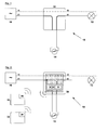
- Fig. 1 eine konventionelle Installation mit einem leitergebundenen Bedienelement zur Ansteuerung eines elektrischen Verbrauchers,
- Fig. 2 eine Fig. 1 entsprechende Ausführungsform der Erfindung,
- Fig. 3, 4 Varianten mit mehreren leitergebundenen Bedienelementen,
- Fig. 5 eine Installation mit mehreren leitergebundenen Bedienelementen und Zeitschaltern,
- Fig. 6 eine Installation mit einem Dimmer, und
- Fig. 7 eine Installation mit zwei Rollladenmotoren.
- 1 shows a conventional installation with a wire-connected control element for controlling an electrical load,
- 2 a corresponding to FIG. 1 embodiment of the invention,
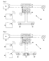
- 3, 4 variants with several wire-bound controls,
- 5 shows an installation with several wire-bound controls and time switches,
- Fig. 6 shows an installation with a dimmer, and
- Fig. 7 shows an installation with two roller shutter motors.
In Fig. 1 wird eine bekannte elektrische Installation 10 mit einem elektrischen Verbraucher 12, vorliegend ein Beleuchtungskörper, mittels Bedienelement 14 ein- und ausgeschaltet und vom elektrischen Netz 16 gespeist. Aus Sicherheitsgründen wird hierbei ein Nullleiter 18 direkt, und ein Phasenleiter 20 über das Bedienelement 14 geführt. Zur Vereinfachung einer sicheren, nicht sichtbaren Verkabelung, wird in der Praxis üblicherweise eine Abzweigdose 22 verwendet.In Fig. 1 , a known
Fig. 2 zeigt eine erfindungsgemässe Installation 10 mit einer Schaltdose 24, die anstelle einer Abzweigdose 22 installiert ist. Die Schaltdose 24 umfasst ein Funk-Kommunikationsmodul, kurz Funkmodul 26, einen Mikrocontroller 28 mit entsprechender Software sowie ein Schaltelement 30, das den Stromkreis 16, 18, 20 mit dem elektrischen Verbraucher 12 schliessen kann. Die Schaltdose 24 kann von einer Heim- oder Gebäudeautomationssteuerung 32, die ebenfalls mit einem Funkmodul 26 ausgerüstet ist, Befehle zum Schliessen des Stromkreises 16, 18, 20 erhalten und über das Schaltelement 30 ausführen. Gleichzeitig kann die Schaltdose 24 die Schaltbewegungen des Bedienelements 14 mit dem Mikrocontroller 28 erfassen, über das Schaltelement 30 ausführen und über das Funkmodul 26 der Heim- oder Gebäudeautomationssteuerung 32 mitteilen. Fig. 2 shows an
Anstatt mit Hilfe des Bedienelements 14 kann der Bewohner auch mit Hilfe einer Fernbedienung 34 den Stromkreis 16, 18, 20 für den elektrischen Verbraucher 12 schliessen. Dabei teilt die Fernbedienung 34 mittels des darin enthaltenen Funkmoduls 26 der Heim- oder Gebäudeautomationssteuerung 32 den entsprechenden Wunsch des Bewohners mit. Die Heim- oder Gebäudeautomationssteuerung 32 übermittelt den Befehl dann wie zuvor beschrieben der Schaltdose 24.Instead of using the
Fig. 3 zeigt eine Installation 10, wie sie bei Räumen mit zwei oder mehr Türen auftritt: Hier wird üblicherweise in der Nähe jeder Türe je ein Bedienelement 14' installiert. Auch in diesem Fall kommt die Schaltdose 24 zum Einsatz, indem sie wie in Fig. 2 beschrieben anstelle einer einfachen Abzweigdose 22 genutzt wird. Fig. 3 shows an
Bei grösseren Benutzerzonen werden üblicherweise Installationen 10 wie in Fig. 4 dargestellt mit Bedienelementen 14" verwendet, die mehr als zwei Einzelschalter umfassen. Solche Bedienelemente 14" können wie in der Zeichnung dargestellt auch in Kombination mit Bedienelementen 14' und/oder mit nicht dargestellten Bedienelementen 14 genutzt werden. Auch in diesen Fällen kommt die Schaltdose 24 gemäss Fig. 2 und 3 zum Einsatz.For larger user zones,
Fig. 5 zeigt eine Installation 10, in der anstelle von Bedienelementen 14, 14', 14" monostabile Taster 36 in Kombination mit einer sogenannte Minuterie (Zeitschalter) 38 zum Einsatz kommt. In einer weiteren, nicht dargestellten Installation 10 wird eine Minuterie 38 ausser Betrieb genommen, wobei die Funktionalität dann von der Heim- oder Gebäudeautomationssteuerung 32 übernommen wird. In beiden Fällen kommt die verwendete Schaltdose 24 gemäss Fig. 2 - 4 zum Einsatz. Fig. 5 shows an
Gemäss Fig. 6 kommt in einer Installation 10 mit einer Schaltdose 24 anstelle eines Schaltelements 30 auch eine Dimmeransteuerung 40 zum Einsatz. Diese steuert ein übliches Dimmerelement 42 an, vorliegend über ein galvanisch getrenntes 0-10 Volt Spannungssignal.According to FIG. 6 , a
Fig. 7 schliesslich zeigt eine Installation 10 mit zwei Verbrauchern 12 beziehungsweise mit zwei Rollladenmotoren 12', welche auch als Sonnenstorenmotoren genutzt werden können. Der Übersichtlichkeit wegen wurden keine weiteren Verbraucher 12, 12' eingezeichnet, es sind deren beliebig viele mit unterschiedlichen Funktionen, in der Regel abhängig von den bereits vorhandenen Installationen. Die Steuerung der verschiedenen Verbraucher 12, 12' erfolgt wiederum durch ein Schaltelement 30, das in diesem Fall mehrere Verbraucher 12, 12' schalten kann. Die Schaltdose 24 erhält die hierzu erforderlichen Schaltbefehle wie beschrieben über die Schalter 14, und/oder ebenso wie beschrieben funk- und/oder infrarotbasiert durch eine Fernbedienung 34, und/oder über die Heim- oder Gebäudeautomationssteuerung 32. Auch in dieser Variante koordiniert die Heim- oder Gebäudeautomationssteuerung 32 wiederum Soll- und Ist-Zustände der Verbraucher 12, 12' und nimmt die Funktion einer Steuerungszentrale wahr.Finally, FIG. 7 shows an
Claims (12)
dadurch gekennzeichnet, dass
characterized in that
Applications Claiming Priority (1)
| Application Number | Priority Date | Filing Date | Title |
|---|---|---|---|
| CH10212005 | 2005-06-16 |
Publications (3)
| Publication Number | Publication Date |
|---|---|
| EP1734636A2 true EP1734636A2 (en) | 2006-12-20 |
| EP1734636A3 EP1734636A3 (en) | 2011-02-16 |
| EP1734636B1 EP1734636B1 (en) | 2013-05-29 |
Family
ID=35923008
Family Applications (1)
| Application Number | Title | Priority Date | Filing Date |
|---|---|---|---|
| EP06405260.8A Active EP1734636B1 (en) | 2005-06-16 | 2006-06-16 | Switchbox |
Country Status (1)
| Country | Link |
|---|---|
| EP (1) | EP1734636B1 (en) |
Cited By (7)
| Publication number | Priority date | Publication date | Assignee | Title |
|---|---|---|---|---|
| DE202007004640U1 (en) * | 2007-03-29 | 2008-08-07 | Vazinkhoo, Kayvan | Monitoring device for electrical appliances |
| EP2012468A2 (en) | 2007-06-19 | 2009-01-07 | Adhoco AG | Scene detection |
| DE102009060435A1 (en) | 2009-12-22 | 2011-06-30 | eQ-3 AG, 26789 | Remote controllable switch |
| EP2395817A1 (en) * | 2010-06-14 | 2011-12-14 | Hager Controls | Interface device between a motion sensor for KNX bus and the lights |
| DE102011015594A1 (en) * | 2011-03-30 | 2012-10-04 | Deutsche Telekom Ag | Switching arrangement for switching on and off e.g. corridor lamp in house, has light and internet protocol switches cooperating such that change of switching condition of arrangement is caused by changing switching position of one switch |
| DE102018108973A1 (en) * | 2018-04-16 | 2019-10-17 | Technisat Digital Gmbh | Device for operating in a home automation set up for switching a switching line |
| DE102018131515B3 (en) | 2018-12-10 | 2019-10-24 | Technisat Digital Gmbh | Switching device for use in a switching circuit and method |
Citations (4)
| Publication number | Priority date | Publication date | Assignee | Title |
|---|---|---|---|---|
| US4990908A (en) * | 1989-03-23 | 1991-02-05 | Michael Tung | Remote power control for dual loads |
| DE19935003A1 (en) * | 1999-07-26 | 2001-02-15 | Osram Opto Semiconductors Gmbh | Mains power supply network with information transmission has wireless transmitter or receiver built into lamp or power socket and connected via converter to mains network |
| WO2003073182A1 (en) * | 2002-02-25 | 2003-09-04 | General Electric Company | Method and apparatus for optimizing a redundant critical control system |
| DE10315623A1 (en) * | 2003-04-04 | 2004-10-14 | Abb Patent Gmbh | Low-voltage module |
-
2006
- 2006-06-16 EP EP06405260.8A patent/EP1734636B1/en active Active
Patent Citations (4)
| Publication number | Priority date | Publication date | Assignee | Title |
|---|---|---|---|---|
| US4990908A (en) * | 1989-03-23 | 1991-02-05 | Michael Tung | Remote power control for dual loads |
| DE19935003A1 (en) * | 1999-07-26 | 2001-02-15 | Osram Opto Semiconductors Gmbh | Mains power supply network with information transmission has wireless transmitter or receiver built into lamp or power socket and connected via converter to mains network |
| WO2003073182A1 (en) * | 2002-02-25 | 2003-09-04 | General Electric Company | Method and apparatus for optimizing a redundant critical control system |
| DE10315623A1 (en) * | 2003-04-04 | 2004-10-14 | Abb Patent Gmbh | Low-voltage module |
Cited By (12)
| Publication number | Priority date | Publication date | Assignee | Title |
|---|---|---|---|---|
| DE202007004640U1 (en) * | 2007-03-29 | 2008-08-07 | Vazinkhoo, Kayvan | Monitoring device for electrical appliances |
| EP2012468A2 (en) | 2007-06-19 | 2009-01-07 | Adhoco AG | Scene detection |
| DE102009060435A1 (en) | 2009-12-22 | 2011-06-30 | eQ-3 AG, 26789 | Remote controllable switch |
| WO2011085840A1 (en) | 2009-12-22 | 2011-07-21 | Rwe Effizienz Gmbh | Remotely controllable switch |
| DE102009060435B4 (en) * | 2009-12-22 | 2011-09-22 | Eq-3 Ag | Remote controllable switch |
| EP2395817A1 (en) * | 2010-06-14 | 2011-12-14 | Hager Controls | Interface device between a motion sensor for KNX bus and the lights |
| FR2961372A1 (en) * | 2010-06-14 | 2011-12-16 | Hager Controls | DEVICE FOR INTERFACING BETWEEN A MOTION DETECTOR FOR KNX BUS AND LUMINAIRES. |
| DE102011015594A1 (en) * | 2011-03-30 | 2012-10-04 | Deutsche Telekom Ag | Switching arrangement for switching on and off e.g. corridor lamp in house, has light and internet protocol switches cooperating such that change of switching condition of arrangement is caused by changing switching position of one switch |
| DE102011015594B4 (en) | 2011-03-30 | 2021-10-14 | Deutsche Telekom Ag | Switching arrangement |
| DE102018108973A1 (en) * | 2018-04-16 | 2019-10-17 | Technisat Digital Gmbh | Device for operating in a home automation set up for switching a switching line |
| DE102018131515B3 (en) | 2018-12-10 | 2019-10-24 | Technisat Digital Gmbh | Switching device for use in a switching circuit and method |
| EP3667863A1 (en) | 2018-12-10 | 2020-06-17 | TechniSat Dresden GmbH | Switching device for use in an alternating circuit and method |
Also Published As
| Publication number | Publication date |
|---|---|
| EP1734636A3 (en) | 2011-02-16 |
| EP1734636B1 (en) | 2013-05-29 |
Similar Documents
| Publication | Publication Date | Title |
|---|---|---|
| EP1734636B1 (en) | Switchbox | |
| DE4425876A1 (en) | Stationary and mobile intelligent socket outlet for consumer loads | |
| WO2011038973A2 (en) | Assembly for installing building systems engineering units | |
| DE10327504B4 (en) | Multifunction device | |
| EP0982642B1 (en) | Process for the control of electrical installations in buildings and a control device for the control of electrical installations in buildings | |
| EP0437696A1 (en) | Remote-controlled connecting device | |
| DE102005028095A1 (en) | Safety system for e.g. electrical stove, has evaluation and control unit sending data frame to shutdown unit, when no movements are detected during given follow-up time, and switching on/off device performing constraint shutdown | |
| EP2950289A1 (en) | Device and system for domestic and building automation | |
| DE102010017102B4 (en) | Installation device and insert device and attachment for an installation device | |
| DE102008050714A1 (en) | Decentrally arranged control device for controlling e.g. roller shutters, has central control unit centrally controlling control device, where roller motors and control unit are connected with control device by plug system | |
| EP1993010B1 (en) | Sensor unit | |
| DE102015121173B4 (en) | Operating system for mechanical and radio-technical initialization of a functionality for installation for flush-mounted boxes | |
| EP1289217B1 (en) | Communication using alternative current half-waves | |
| DE3623805A1 (en) | Signal transmission system for remotely controlling and monitoring electrical or electronic devices | |
| DE102017105196A1 (en) | Control module for controlling electrical devices | |
| DE19610381C2 (en) | Installation bus system for a track lighting | |
| EP2012468A2 (en) | Scene detection | |
| EP3089318B1 (en) | Device for thorough supply of a consumer with electrical energy | |
| EP2447795B1 (en) | System for controlling function devices in buildings | |
| DE10312183A1 (en) | Micro controller based bus system is used in rooms and buildings for operation of services such as heating and lighting | |
| WO2013156392A1 (en) | Control device for low-voltage switchgears | |
| EP3664304B1 (en) | Input and output of data and data transport via electrical power line of lighting systems | |
| DE10204809A1 (en) | System for wiring up a building has an mains electrical supply for residential units and a separate bus network linked by wires for personal computers and so on | |
| EP2299340A1 (en) | Centre, system and method for controlling function devices in buildings | |
| DE202023102814U1 (en) | Control and management system of the elements of a house |
Legal Events
| Date | Code | Title | Description |
|---|---|---|---|
| PUAI | Public reference made under article 153(3) epc to a published international application that has entered the european phase |
Free format text: ORIGINAL CODE: 0009012 |
|
| AK | Designated contracting states |
Kind code of ref document: A2 Designated state(s): AT BE BG CH CY CZ DE DK EE ES FI FR GB GR HU IE IS IT LI LT LU LV MC NL PL PT RO SE SI SK TR |
|
| AX | Request for extension of the european patent |
Extension state: AL BA HR MK YU |
|
| PUAL | Search report despatched |
Free format text: ORIGINAL CODE: 0009013 |
|
| AK | Designated contracting states |
Kind code of ref document: A3 Designated state(s): AT BE BG CH CY CZ DE DK EE ES FI FR GB GR HU IE IS IT LI LT LU LV MC NL PL PT RO SE SI SK TR |
|
| AX | Request for extension of the european patent |
Extension state: AL BA HR MK RS |
|
| 17P | Request for examination filed |
Effective date: 20110809 |
|
| REG | Reference to a national code |
Ref country code: DE Ref legal event code: R079 Ref document number: 502006012902 Country of ref document: DE Free format text: PREVIOUS MAIN CLASS: H02J0013000000 Ipc: H05B0037020000 |
|
| AKX | Designation fees paid |
Designated state(s): AT BE BG CH CY CZ DE DK EE ES FI FR GB GR HU IE IS IT LI LT LU LV MC NL PL PT RO SE SI SK TR |
|
| AXX | Extension fees paid |
Extension state: MK Payment date: 20110816 Extension state: HR Payment date: 20110816 Extension state: BA Payment date: 20110816 Extension state: AL Payment date: 20110816 Extension state: RS Payment date: 20110816 |
|
| RIC1 | Information provided on ipc code assigned before grant |
Ipc: H02J 13/00 20060101ALI20111013BHEP Ipc: H05B 37/02 20060101AFI20111013BHEP |
|
| GRAP | Despatch of communication of intention to grant a patent |
Free format text: ORIGINAL CODE: EPIDOSNIGR1 |
|
| GRAJ | Information related to disapproval of communication of intention to grant by the applicant or resumption of examination proceedings by the epo deleted |
Free format text: ORIGINAL CODE: EPIDOSDIGR1 |
|
| GRAP | Despatch of communication of intention to grant a patent |
Free format text: ORIGINAL CODE: EPIDOSNIGR1 |
|
| GRAS | Grant fee paid |
Free format text: ORIGINAL CODE: EPIDOSNIGR3 |
|
| GRAA | (expected) grant |
Free format text: ORIGINAL CODE: 0009210 |
|
| AK | Designated contracting states |
Kind code of ref document: B1 Designated state(s): AT BE BG CH CY CZ DE DK EE ES FI FR GB GR HU IE IS IT LI LT LU LV MC NL PL PT RO SE SI SK TR |
|
| AX | Request for extension of the european patent |
Extension state: AL BA HR MK RS |
|
| REG | Reference to a national code |
Ref country code: GB Ref legal event code: FG4D Free format text: NOT ENGLISH |
|
| REG | Reference to a national code |
Ref country code: CH Ref legal event code: EP |
|
| REG | Reference to a national code |
Ref country code: AT Ref legal event code: REF Ref document number: 615059 Country of ref document: AT Kind code of ref document: T Effective date: 20130615 |
|
| REG | Reference to a national code |
Ref country code: IE Ref legal event code: FG4D Free format text: LANGUAGE OF EP DOCUMENT: GERMAN |
|
| REG | Reference to a national code |
Ref country code: DE Ref legal event code: R096 Ref document number: 502006012902 Country of ref document: DE Effective date: 20130725 |
|
| REG | Reference to a national code |
Ref country code: CH Ref legal event code: NV Representative=s name: KELLER AND PARTNER PATENTANWAELTE AG WINTERTHU, CH |
|
| REG | Reference to a national code |
Ref country code: LT Ref legal event code: MG4D |
|
| PG25 | Lapsed in a contracting state [announced via postgrant information from national office to epo] |
Ref country code: IS Free format text: LAPSE BECAUSE OF FAILURE TO SUBMIT A TRANSLATION OF THE DESCRIPTION OR TO PAY THE FEE WITHIN THE PRESCRIBED TIME-LIMIT Effective date: 20130929 Ref country code: PT Free format text: LAPSE BECAUSE OF FAILURE TO SUBMIT A TRANSLATION OF THE DESCRIPTION OR TO PAY THE FEE WITHIN THE PRESCRIBED TIME-LIMIT Effective date: 20130930 Ref country code: FI Free format text: LAPSE BECAUSE OF FAILURE TO SUBMIT A TRANSLATION OF THE DESCRIPTION OR TO PAY THE FEE WITHIN THE PRESCRIBED TIME-LIMIT Effective date: 20130529 Ref country code: SE Free format text: LAPSE BECAUSE OF FAILURE TO SUBMIT A TRANSLATION OF THE DESCRIPTION OR TO PAY THE FEE WITHIN THE PRESCRIBED TIME-LIMIT Effective date: 20130529 Ref country code: SI Free format text: LAPSE BECAUSE OF FAILURE TO SUBMIT A TRANSLATION OF THE DESCRIPTION OR TO PAY THE FEE WITHIN THE PRESCRIBED TIME-LIMIT Effective date: 20130529 Ref country code: ES Free format text: LAPSE BECAUSE OF FAILURE TO SUBMIT A TRANSLATION OF THE DESCRIPTION OR TO PAY THE FEE WITHIN THE PRESCRIBED TIME-LIMIT Effective date: 20130909 Ref country code: LT Free format text: LAPSE BECAUSE OF FAILURE TO SUBMIT A TRANSLATION OF THE DESCRIPTION OR TO PAY THE FEE WITHIN THE PRESCRIBED TIME-LIMIT Effective date: 20130529 Ref country code: GR Free format text: LAPSE BECAUSE OF FAILURE TO SUBMIT A TRANSLATION OF THE DESCRIPTION OR TO PAY THE FEE WITHIN THE PRESCRIBED TIME-LIMIT Effective date: 20130830 |
|
| PGFP | Annual fee paid to national office [announced via postgrant information from national office to epo] |
Ref country code: BE Payment date: 20130725 Year of fee payment: 8 Ref country code: ES Payment date: 20130729 Year of fee payment: 8 Ref country code: DK Payment date: 20130730 Year of fee payment: 8 Ref country code: NL Payment date: 20130730 Year of fee payment: 8 Ref country code: IE Payment date: 20130730 Year of fee payment: 8 |
|
| REG | Reference to a national code |
Ref country code: NL Ref legal event code: VDEP Effective date: 20130529 |
|
| PG25 | Lapsed in a contracting state [announced via postgrant information from national office to epo] |
Ref country code: BG Free format text: LAPSE BECAUSE OF FAILURE TO SUBMIT A TRANSLATION OF THE DESCRIPTION OR TO PAY THE FEE WITHIN THE PRESCRIBED TIME-LIMIT Effective date: 20130829 Ref country code: PL Free format text: LAPSE BECAUSE OF FAILURE TO SUBMIT A TRANSLATION OF THE DESCRIPTION OR TO PAY THE FEE WITHIN THE PRESCRIBED TIME-LIMIT Effective date: 20130529 |
|
| PGFP | Annual fee paid to national office [announced via postgrant information from national office to epo] |
Ref country code: GB Payment date: 20130730 Year of fee payment: 8 |
|
| PG25 | Lapsed in a contracting state [announced via postgrant information from national office to epo] |
Ref country code: LV Free format text: LAPSE BECAUSE OF FAILURE TO SUBMIT A TRANSLATION OF THE DESCRIPTION OR TO PAY THE FEE WITHIN THE PRESCRIBED TIME-LIMIT Effective date: 20130529 |
|
| PG25 | Lapsed in a contracting state [announced via postgrant information from national office to epo] |
Ref country code: CZ Free format text: LAPSE BECAUSE OF FAILURE TO SUBMIT A TRANSLATION OF THE DESCRIPTION OR TO PAY THE FEE WITHIN THE PRESCRIBED TIME-LIMIT Effective date: 20130529 Ref country code: EE Free format text: LAPSE BECAUSE OF FAILURE TO SUBMIT A TRANSLATION OF THE DESCRIPTION OR TO PAY THE FEE WITHIN THE PRESCRIBED TIME-LIMIT Effective date: 20130529 Ref country code: DK Free format text: LAPSE BECAUSE OF FAILURE TO SUBMIT A TRANSLATION OF THE DESCRIPTION OR TO PAY THE FEE WITHIN THE PRESCRIBED TIME-LIMIT Effective date: 20130529 Ref country code: SK Free format text: LAPSE BECAUSE OF FAILURE TO SUBMIT A TRANSLATION OF THE DESCRIPTION OR TO PAY THE FEE WITHIN THE PRESCRIBED TIME-LIMIT Effective date: 20130529 |
|
| PG25 | Lapsed in a contracting state [announced via postgrant information from national office to epo] |
Ref country code: RO Free format text: LAPSE BECAUSE OF FAILURE TO SUBMIT A TRANSLATION OF THE DESCRIPTION OR TO PAY THE FEE WITHIN THE PRESCRIBED TIME-LIMIT Effective date: 20130529 Ref country code: NL Free format text: LAPSE BECAUSE OF FAILURE TO SUBMIT A TRANSLATION OF THE DESCRIPTION OR TO PAY THE FEE WITHIN THE PRESCRIBED TIME-LIMIT Effective date: 20130529 Ref country code: MC Free format text: LAPSE BECAUSE OF FAILURE TO SUBMIT A TRANSLATION OF THE DESCRIPTION OR TO PAY THE FEE WITHIN THE PRESCRIBED TIME-LIMIT Effective date: 20130529 |
|
| PLBE | No opposition filed within time limit |
Free format text: ORIGINAL CODE: 0009261 |
|
| STAA | Information on the status of an ep patent application or granted ep patent |
Free format text: STATUS: NO OPPOSITION FILED WITHIN TIME LIMIT |
|
| 26N | No opposition filed |
Effective date: 20140303 |
|
| REG | Reference to a national code |
Ref country code: DE Ref legal event code: R097 Ref document number: 502006012902 Country of ref document: DE Effective date: 20140303 |
|
| GBPC | Gb: european patent ceased through non-payment of renewal fee |
Effective date: 20140616 |
|
| REG | Reference to a national code |
Ref country code: IE Ref legal event code: MM4A |
|
| REG | Reference to a national code |
Ref country code: CH Ref legal event code: PCAR Free format text: NEW ADDRESS: EIGERSTRASSE 2 POSTFACH, 3000 BERN 14 (CH) |
|
| PG25 | Lapsed in a contracting state [announced via postgrant information from national office to epo] |
Ref country code: IE Free format text: LAPSE BECAUSE OF NON-PAYMENT OF DUE FEES Effective date: 20140616 |
|
| PG25 | Lapsed in a contracting state [announced via postgrant information from national office to epo] |
Ref country code: GB Free format text: LAPSE BECAUSE OF NON-PAYMENT OF DUE FEES Effective date: 20140616 |
|
| PG25 | Lapsed in a contracting state [announced via postgrant information from national office to epo] |
Ref country code: TR Free format text: LAPSE BECAUSE OF FAILURE TO SUBMIT A TRANSLATION OF THE DESCRIPTION OR TO PAY THE FEE WITHIN THE PRESCRIBED TIME-LIMIT Effective date: 20130529 Ref country code: CY Free format text: LAPSE BECAUSE OF FAILURE TO SUBMIT A TRANSLATION OF THE DESCRIPTION OR TO PAY THE FEE WITHIN THE PRESCRIBED TIME-LIMIT Effective date: 20130529 |
|
| PG25 | Lapsed in a contracting state [announced via postgrant information from national office to epo] |
Ref country code: LU Free format text: LAPSE BECAUSE OF NON-PAYMENT OF DUE FEES Effective date: 20130616 Ref country code: HU Free format text: LAPSE BECAUSE OF FAILURE TO SUBMIT A TRANSLATION OF THE DESCRIPTION OR TO PAY THE FEE WITHIN THE PRESCRIBED TIME-LIMIT; INVALID AB INITIO Effective date: 20060616 |
|
| REG | Reference to a national code |
Ref country code: FR Ref legal event code: PLFP Year of fee payment: 11 |
|
| PGFP | Annual fee paid to national office [announced via postgrant information from national office to epo] |
Ref country code: DE Payment date: 20160621 Year of fee payment: 11 Ref country code: CH Payment date: 20160617 Year of fee payment: 11 |
|
| PGFP | Annual fee paid to national office [announced via postgrant information from national office to epo] |
Ref country code: FR Payment date: 20160627 Year of fee payment: 11 Ref country code: AT Payment date: 20160621 Year of fee payment: 11 |
|
| PGFP | Annual fee paid to national office [announced via postgrant information from national office to epo] |
Ref country code: IT Payment date: 20160628 Year of fee payment: 11 |
|
| PG25 | Lapsed in a contracting state [announced via postgrant information from national office to epo] |
Ref country code: BE Free format text: LAPSE BECAUSE OF NON-PAYMENT OF DUE FEES Effective date: 20140630 |
|
| REG | Reference to a national code |
Ref country code: DE Ref legal event code: R119 Ref document number: 502006012902 Country of ref document: DE |
|
| REG | Reference to a national code |
Ref country code: CH Ref legal event code: PL |
|
| REG | Reference to a national code |
Ref country code: AT Ref legal event code: MM01 Ref document number: 615059 Country of ref document: AT Kind code of ref document: T Effective date: 20170616 |
|
| REG | Reference to a national code |
Ref country code: FR Ref legal event code: ST Effective date: 20180228 |
|
| PG25 | Lapsed in a contracting state [announced via postgrant information from national office to epo] |
Ref country code: CH Free format text: LAPSE BECAUSE OF NON-PAYMENT OF DUE FEES Effective date: 20170630 Ref country code: LI Free format text: LAPSE BECAUSE OF NON-PAYMENT OF DUE FEES Effective date: 20170630 Ref country code: DE Free format text: LAPSE BECAUSE OF NON-PAYMENT OF DUE FEES Effective date: 20180103 |
|
| PG25 | Lapsed in a contracting state [announced via postgrant information from national office to epo] |
Ref country code: FR Free format text: LAPSE BECAUSE OF NON-PAYMENT OF DUE FEES Effective date: 20170630 Ref country code: AT Free format text: LAPSE BECAUSE OF NON-PAYMENT OF DUE FEES Effective date: 20170616 Ref country code: IT Free format text: LAPSE BECAUSE OF NON-PAYMENT OF DUE FEES Effective date: 20170616 |