EP1734619B1 - A connector and connector assembly of the movable member type - Google Patents
A connector and connector assembly of the movable member type Download PDFInfo
- Publication number
- EP1734619B1 EP1734619B1 EP06010429A EP06010429A EP1734619B1 EP 1734619 B1 EP1734619 B1 EP 1734619B1 EP 06010429 A EP06010429 A EP 06010429A EP 06010429 A EP06010429 A EP 06010429A EP 1734619 B1 EP1734619 B1 EP 1734619B1
- Authority
- EP
- European Patent Office
- Prior art keywords
- housing
- movable member
- lever
- connector
- mating
- Prior art date
- Legal status (The legal status is an assumption and is not a legal conclusion. Google has not performed a legal analysis and makes no representation as to the accuracy of the status listed.)
- Active
Links
Images


Classifications
-
- H—ELECTRICITY
- H01—ELECTRIC ELEMENTS
- H01R—ELECTRICALLY-CONDUCTIVE CONNECTIONS; STRUCTURAL ASSOCIATIONS OF A PLURALITY OF MUTUALLY-INSULATED ELECTRICAL CONNECTING ELEMENTS; COUPLING DEVICES; CURRENT COLLECTORS
- H01R13/00—Details of coupling devices of the kinds covered by groups H01R12/70 or H01R24/00 - H01R33/00
- H01R13/62—Means for facilitating engagement or disengagement of coupling parts or for holding them in engagement
- H01R13/629—Additional means for facilitating engagement or disengagement of coupling parts, e.g. aligning or guiding means, levers, gas pressure electrical locking indicators, manufacturing tolerances
- H01R13/62933—Comprising exclusively pivoting lever
- H01R13/62938—Pivoting lever comprising own camming means
-
- H—ELECTRICITY
- H01—ELECTRIC ELEMENTS
- H01R—ELECTRICALLY-CONDUCTIVE CONNECTIONS; STRUCTURAL ASSOCIATIONS OF A PLURALITY OF MUTUALLY-INSULATED ELECTRICAL CONNECTING ELEMENTS; COUPLING DEVICES; CURRENT COLLECTORS
- H01R13/00—Details of coupling devices of the kinds covered by groups H01R12/70 or H01R24/00 - H01R33/00
- H01R13/62—Means for facilitating engagement or disengagement of coupling parts or for holding them in engagement
- H01R13/629—Additional means for facilitating engagement or disengagement of coupling parts, e.g. aligning or guiding means, levers, gas pressure electrical locking indicators, manufacturing tolerances
- H01R13/62933—Comprising exclusively pivoting lever
- H01R13/6295—Pivoting lever comprising means indicating incorrect coupling of mating connectors
-
- H—ELECTRICITY
- H01—ELECTRIC ELEMENTS
- H01R—ELECTRICALLY-CONDUCTIVE CONNECTIONS; STRUCTURAL ASSOCIATIONS OF A PLURALITY OF MUTUALLY-INSULATED ELECTRICAL CONNECTING ELEMENTS; COUPLING DEVICES; CURRENT COLLECTORS
- H01R13/00—Details of coupling devices of the kinds covered by groups H01R12/70 or H01R24/00 - H01R33/00
- H01R13/62—Means for facilitating engagement or disengagement of coupling parts or for holding them in engagement
- H01R13/629—Additional means for facilitating engagement or disengagement of coupling parts, e.g. aligning or guiding means, levers, gas pressure electrical locking indicators, manufacturing tolerances
- H01R13/62933—Comprising exclusively pivoting lever
- H01R13/62955—Pivoting lever comprising supplementary/additional locking means
-
- H—ELECTRICITY
- H01—ELECTRIC ELEMENTS
- H01R—ELECTRICALLY-CONDUCTIVE CONNECTIONS; STRUCTURAL ASSOCIATIONS OF A PLURALITY OF MUTUALLY-INSULATED ELECTRICAL CONNECTING ELEMENTS; COUPLING DEVICES; CURRENT COLLECTORS
- H01R13/00—Details of coupling devices of the kinds covered by groups H01R12/70 or H01R24/00 - H01R33/00
- H01R13/46—Bases; Cases
- H01R13/52—Dustproof, splashproof, drip-proof, waterproof, or flameproof cases
- H01R13/5219—Sealing means between coupling parts, e.g. interfacial seal
Definitions
- the present invention relates to a connector and connector assembly of the movable member type, particularly to a lever type connector and connector assembly.
- Document GB 2 322 242 A discloses a connector of the movable member type in which a movable member having an operable portion at or near a side plate is movably mounted in or on a housing.
- the movable member comprises at least one cam member engageable with at least one mating cam member formed on a mating housing so that it can be guided along the cam member as the movable member is operated, thereby connecting the housing with the mating housing.
- an engaging portion engageable with a locking projection is formed on the mating housing. Immediately before the housing is properly connected with the mating housing, the locking projection is engaged with the engaging portion and receives a force via the engaging portion as the movable member is operated
- Document JP 2001 326024 A discloses a lever connector with a cover, which is mounted on the rear face side of a female housing, and which is equipped with a lever in advance. As the cover is installed, the level is mounted on the female housing.
- Document US 2002/0004326 A1 discloses a connector support mechanism which comprises a female connector and a male connector.
- a cam lever formed with a cam groove which guides a boss protruding from the female connector is turnably pivoted by the male connector. In a state in which the boss is inserted into the cam groove, if the cam lever turns, the female connector and the male connector are fitted to each other.
- a lever-type connector is known from Japanese Unexamined Patent Publication No. 2001-326024 .
- This connector is constructed such that a lever is rotatably mounted on a female housing and male and female housings are connected by guiding cam pins formed on the male housing along cam grooves formed in the lever as the lever is rotated.
- an operable portion of the lever is located at a position in the vicinity of one lateral end of the female housing radially distanced from an axis of rotation of the lever, and is operated in a direction along a connecting direction of the female housing.
- the present invention was developed in view of the above problem and an object thereof is to allowing to correct the posture of one housing in the process of connecting the two housings.
- a connector of the movable member type in particular of the lever type, in which a movable member such as a lever having an operable portion at or near a side plate is movably mounted in or on or to a housing, the movable member comprising at least one cam member engageable with at least one mating cam member formed on a mating housing so that it can be guided along the cam member as the movable member is operated, thereby connecting the housing with the mating housing, wherein:
- the locking projection receives the force acting in the direction substantially along the connecting direction of the mating housing by being brought into engagement with the engaging portion formed at the side of the movable member opposite to the operable portion.
- the movable member is rotatably or pivotably mounted to the housing and the operable portion of the movable member is located at a lateral end portion of the housing radially distanced from an axis of rotation of the movable member.
- the movable member is operated in a direction along a connecting direction of the housing immediately before the two housings are properly connected.
- a lever-type connector in which a lever having an operable portion at a leading-end side of a side plate is rotatably mounted in a first housing, a cam pin formed on a second housing is guided along a cam groove formed in the side plate as the lever is rotated, thereby connecting the two housings, and the operable portion of the lever is located at a lateral end portion of the first housing radially distanced from an axis of rotation of the lever and is operated in a direction along a connecting direction of the first housing immediately before the two housings are properly connected, wherein:
- the locking projection receives the force acting in the direction along the connecting direction of the second housing by being brought into engagement with the engaging portion formed at the side of the lever opposite to the operable portion.
- the housing or first housing is a harness-side housing to be connected with wires forming a wiring harness
- the mating housing or second housing is a waiting-side housing to be disposed on a fixed member.
- At least one guiding wall extending substantially in the connecting directions of the two housings is formed at a position substantially corresponding to the locking projection of the mating housing or second housing in or near an end surface of the housing or first housing at a side to be connected with the m ⁇ ting housing or second housing, and comes or can come substantially into sliding contact with the locking projection during a connecting operation of the two housings.
- the locking projection of the mating/second housing guides or can substantially guide the connecting and separating operation of the two housings by coming substantially into sliding contact with the guiding wall formed in the first housing. Therefore, the two housings can be connected and separated in their substantially proper postures.
- the movable member is mountable to or in or on the (first) housing in two transversely substantially symmetrical postures, and/or a pair of locking projections are formed at two transversely symmetrical positions with respect to the second housing.
- At least one pair of supporting shafts are formed on the housing at two substantially transversely symmetrical positions with respect to the housing, the movable member is rotatably or pivotably mounted on one of the supporting shafts, thereby being made mountable in two substantially transversely symmetrical postures with respect to the housing.
- the operable portion of the movable member mounted on the one of the supporting shafts is located at a side of the one supporting shaft opposite to the other supporting shaft immediately before the two housings are properly connected.
- a pair of supporting shafts are formed on the first housing at two transversely symmetrical positions with respect to the first housing, the lever is rotatably mounted on one of the supporting shafts, thereby being made mountable in two transversely symmetrical postures with respect to the first housing, the operable portion of the lever mounted on the one of the supporting shafts is located at a side of the one supporting shaft opposite to the other supporting shaft immediately before the two housings are properly connected, a pair of cam pins are formed on the second housing at positions corresponding to the cam groove of the lever in the respective states where the lever is mounted on the one or the other of the supporting shafts, and out of the two cam pins, the one not engaged with the cam groove serves as the locking projection.
- the construction of the second housing can be simplified as compared to a case where the locking projection is separately provided.
- a connector assembly comprising a connector of the movable member type according to the invention or a preferred embodiment thereof and a mating connector having the mating connector housing, the locking projection being formed on the mating housing.
- a pair of mating cam members are formed on the mating housing at positions corresponding to the cam member of the movable member in the respective states where the movable member is mounted on the one or the other of the supporting shafts.
- the one not engaged with the cam member serves as the locking projection.
- a connector having a movable operable member, preferably a lever, according to this embodiment is constructed such that a female housing 10 (corresponding to a preferred first housing) and a male housing 11 (corresponding to a preferred second housing) are or can be connected and separated (or the connection and separation thereof may be assisted) by means of a movable member, preferably comprising a lever, to be provided in or on the female housing 10.
- the female and male housings 10, 11 are to be connected along a connecting direction CD.
- sides of the two housings 10, 11 to be connected are referred to as front sides and reference is made to FIG. 2 concerning vertical direction.
- the male housing 11 is made e.g. of a synthetic resin material and preferably is a waiting-side housing arranged or arrangeable on an unillustrated fixed member as shown in FIGS. 2 and 3 .
- a receptacle 13 having an open front side is formed at or near a front side of the male housing 11, and a terminal accommodating portion 15 for accommodating one or more male terminal fittings 14 is formed behind or adjacent to the receptacle 13.
- One or more mounting lock portions 16 used to mount the male housing 11 on the fixed member are formed on the outer lateral (left and/or right) side surface(s) of the terminal accommodating portion 15 in FIG. 1 .
- one or more cavities 17 extending substantially in forward and backward directions FBD are formed in the terminal accommodating portion 15, and the male terminal fittings 14 are to be at least partly inserted into the respective cavities 17 from an insertion side, preferably substantially from behind.
- Each male terminal fitting 14 is comprised of a main portion 18 and a barrel portion 20 provided behind the main portion 18 and to be connected (preferably crimped or folded or bent into connection) with a wire 19, wherein a (preferably substantially narrow and long) tab piece 21 extends substantially forward from or near the front end of the main portion 18.
- a (preferably substantially cantilever-shaped) locking portion 22 resiliently deformable and preferably extending substantially forward projects at an inner wall of each cavity 17.
- This locking portion 22 is or can be resiliently engaged with the terminal fitting 14, preferably with the main portion 18, to retain the male terminal fitting 14.
- the tab piece 21 With the male terminal fitting 14 at least partly accommodated in the cavity 17, the tab piece 21 at least partly projects into the receptacle 13.
- a retainer 23 preferably is mountable into a front-end portion of the terminal accommodating portion 15 to (preferably doubly) lock the male terminal fittings 14.
- a waterproof resilient plug or waterproof rubber plug 24 preferably is so at least partly fitted on a rear part of the barrel portion 20 as to at least partly surround the barrel portion 20 together with an insulation coating of the wire 19, wherein sealing preferably is to be provided between the wire 19 and the inner circumferential surface of the cavity 17 by the resilient close contact between the outer circumferential surface of the waterproof resilient/rubber plug 24 and the inner circumferential surface of the cavity 17.
- a substantially cylindrical cam pin 25 projecting laterally or upward (or in a direction at an angle different from 0° or 180°, preferably substantially normal to the connecting direction CD) is formed at a position at or near the front end of the outer surface of the lateral (upper) wall of the receptacle 13 preferably substantially in the transverse center in FIG. 3 , and is engageable with a cam groove 26 of a lever 12 (as a preferred movable member) to be described later.
- a larger-diameter portion 27 enlarged in one or more radially outward directions of the cam pin 25 is formed at the upper or distal end of the cam pin 25, and a (preferably substantially vertical) separation of the cam groove 26 and the cam pin 25 is prevented by the engagement of a cam-pin receiving portion 64 of the lever 12 to be described later with the bottom or inner edge of the larger-diameter portion 27.
- a slanted or rounded surface 30 inclined down or inwardly toward the front is formed at or near the front end of each guiding rib 28 in order to facilitate a movement of a partial or first locking piece 41 of the lever 12 to be described later onto the guiding rib 28.
- a phantom straight line 39 (see FIG.
- the female housing 10 is made e.g. of a synthetic resin material and, and an inner tube portion 32 in which one or more, preferably a plurality of cavities 17 extending substantially in forward and backward directions FBD are formed substantially side by side along width direction is formed inside an outer tube portion 31 at one or more stages as shown in FIGS. 2 and 4 .
- a female terminal fitting 33 is to be at least partly inserted into each cavity 17 from an inserting side, preferably substantially from behind, to be locked and retained by a locking portion 22 formed in or at the cavity 17.
- Each female terminal fitting 33 is comprised of a (preferably substantially rectangular) tube portion 34 which preferably is substantially in the form of a rectangular tube and into which the tab piece 21 of the male terminal fitting 14 at least partly accommodated in the male housing 11 is to be at least partly inserted, and a wire connection portion (preferably comprising a barrel portion 20) provided behind or adjacent to the (rectangular) tube portion 34 and to be connected (preferably substantially crimped or bent or folded into connection) with a wire 19.
- a resiliently deformable resilient contact piece (not shown) is formed in the (rectangular) tube portion 34 to be resiliently brought into contact with the tab piece 21 at least partly inserted into the (rectangular) tube portion 34.
- a waterproof resilient plug or waterproof rubber plug 24 is so fitted on or to a rear part of the barrel portion 20 as to at least partly surround the barrel portion 20 preferably together with an insulation coating of the wire 19, wherein sealing is provided between the wire 19 and the inner circumferential surface of the cavity 17 by the resilient close contact between the outer circumferential surface of the waterproof resilient/rubber plug 24 and the inner circumferential surface of the cavity 17.
- a (preferably substantially cap-shaped) retainer 23 preferably is to be mounted on or to a front-end portion of the inner tube portion 32 in the female housing 10 to (preferably doubly) lock the female terminal fittings 33.
- the female housing 10 is connected with the wires 19 forming a wiring harness and serves or may serve as a harness-side or movable side housing.
- the receptacle 13 of the aforementioned male housing 11 is at least partly insertable into a clearance between the inner tube portion 32 and the outer tube portion 31.
- a tubular seal ring 35 preferably made of resilient material such as rubber, is to be mounted on or to the outer circumferential surface of the inner tube portion 32 near an intermediate part (preferably near or at a substantially middle part) of the inner tube portion 32 with respect to forward and backward directions FBD. Sealing preferably is provided between the male housing 11 and the female housing 10 by the resilient close contact between one or more (e.g. three) lips 36 circumferentially formed on the outer circumferential surface of the seal ring 35 over at least part, preferably over the substantially entire circumference and the inner circumferential surface of the receptacle 13 of the male housing 11 as shown.
- a lever accommodating space 37 (as a preferred movable member accommodating space) for at least partly accommodating the movable member, preferably the lever 12, is so formed at a lateral (upper) side of the outer tube portion 31 as to penetrate substantially in forward and backward directions FBD.
- a (preferably substantially cylindrical) supporting shaft 38 extends downward from the ceiling wall of this lever accommodating space 37.
- the lever accommodating space 37 preferably is substantially transversely symmetrically formed with respect to the axis of symmetry 39 passing the center axis of the supporting shaft 38.
- a (preferably substantially rectangular) notch 40 is so formed in the bottom or inner wall of the lever accommodating space 37 as part of the outer tube portion 31 as to extend substantially backward from the front edge.
- a locking piece 41 of the lever 12 to be described later is or can be engaged with one of the receiving portions 29 in a standby state of the lever 12 to be described later.
- the lever 12 (as the preferred movable member) is made e.g. of a synthetic resin material and provided with a side plate 42 preferably substantially having such a comb-shape obtained by cutting off a rear-end area of the peripheral portion of a circle when viewed from above, and an operable portion 43 bulging out laterally (slightly to left) from the rear end of the side plate 42 at a lateral (left) side in FIG. 1 .
- the lever 12 preferably is substantially vertically symmetrical (or symmetrical with respect to an axis or plane substantially normal to the axis of rotation) as a whole.
- This lever 12 is so mounted at least partly in the lever accommodating space 37 of the female housing 10 as to be rotatable or pivotable between a standby position SP (as a preferred first position) and a connected position CP (as a preferred second position).
- the standby position SP first position refers to a position of the lever 12 where the entrance of the cam pin 25 formed on the male housing 11 is permitted to at least partly enter a cam groove 26 formed in the side plate 42 of the lever 12 (see FIG. 6 )
- the connected position CP second position referred to as a position of the lever 12 where the two housings 10, 20 are substantially properly connected (see FIG. 1 ).
- a shaft hole or recess 44 is formed to vertically penetrate the center of the side plate 42, and the aforementioned supporting shaft 38 is or can be at least partly inserted into this shaft hole 44.
- the cam groove 26 oblique to both circumferential direction and radial directions (or having a spiral-like shape) substantially centered on the shaft hole 44 is formed before the shaft hole 44 in the side plate 42.
- the campin receiving portion 64 for receiving the larger-diameter portion 27 of the cam pin 25 is formed at the upper edge of the cam groove 26 over the entire length of the cam groove 26.
- the locking piece 41 for holding or positioning the lever 12 at the standby position SP is formed at a position of the side plate 42 at the lateral (right) side of the shaft hole 44.
- the locking piece 41 preferably is substantially in the form of a plate narrow and long in forward and backward directions FBD, and has the front end thereof supported on the side plate 42 while projecting backward.
- This resilient locking piece 41 is resiliently deformable upward and downward or inwardly and outwardly or towards and away from the housing 10 with the base end (front end) as a supporting point.
- the rear end of the locking piece 41 is engaged with the aforementioned receiving portion 29 when the lever 12 is at the standby position SP.
- the entrance of the cam groove 26 preferably is located substantially on the axis of symmetry 39 passing the supporting shaft 38 of the lever 12.
- a resilient lock piece 45 (preferably substantially in the form of a narrow and long plate extending substantially in forward and backward directions FBD) is formed at the lateral (left) rear side of the side plate 42.
- This resilient lock piece 45 preferably is a cantilever extending substantially backward from its front end, and is resiliently deformable upward and downward or inwardly and outwardly or towards and away from the housing 10.
- One or more vertically or outwardly projecting lock projections 46 are formed at a position in the vicinity of a substantial center of the resilient lock piece 45 with respect to forward and backward directions FBD.
- the resilient lock piece 45 holds or positions the lever 12 at the connected position CP (second position) preferably by the engagement of the above lock projection 46 and one of a pair of return preventing portions 47 preferably substantially transversely symmetrically formed in the lever accommodating space 37 with respect to the lever accommodating space 37 with the lever 12 located at the connected position CP.
- One or more steps dented inwardly with respect to the thickness of the side plate 42 preferably are formed in areas of both upper and lower surfaces of the side plate 42 where the front end of the resilient lock piece 45 is formed, and these one or more steps serve as one or more holding steps 48 for holding the lever 12 at the standby position SP by coming into engagement with the return preventing portion 47 with the lever 12 located at the standby position SP.
- one or more supporting shaft escaping grooves 49 for letting the supporting shaft 38 escape upon mounting the lever 12 in the female housing 10 are so formed by recessing the respective surface(s), preferably both lateral (upper and lower) surfaces, of the side plate 42 inwardly with respect to the thickness direction TD of the side plate 42 as to extend from a position slightly more outward than the shaft hole 44 toward the entrance of the cam groove 26.
- a slanted surface 30 for facilitating a movement of the supporting shaft 38 beyond a portion of the side plate 42 between the supporting shaft escaping groove 49 and the shaft hole 44 is formed at an end of each supporting-shaft escaping groove 49 toward the shaft hole 44.
- one or more return-preventing portion escaping grooves 50 for letting the return preventing portion 47 upon mounting the lever 12 in the female housing 10 are so formed by recessing both respective surface(s), the lateral (upper and lower) surfaces of the side plate 42 inwardly with respect to the thickness direction TD of the side plate 42 as to extend forward from a position slightly before the holding steps 48 in FIG. 6 .
- a slanted or bent surface 30 for facilitating a movement of the return-preventing portion 47 beyond a portion of the side plate 42 between the holding step 48 and the return-preventing portion escaping groove 50 is formed at or near the rear edge of each return-preventing portion escaping groove 50 in FIG. 6 .
- each recesses 51 dented inwardly with respect to the thickness direction TD of the side plate 42 of the lever 12 are formed at a right rear end of the lever 12 in FIG. 1 for letting the return-preventing portion 47 escape upon mounting the lever 12 into the female housing 10.
- a side wall of each recess 51 is or may be engaged with the return-preventing portion 47 to hold the lever 12 at the connected position CP when the lever 12 is at the connected position CP.
- one or more, preferably a pair of locking projections 52 projecting upward or outward are formed preferably substantially at transversely symmetrical positions with respect to a phantom axis (axis of symmetry 39) extending substantially along forward and backward directions FBD and passing the center axis of the cam pin 25, these positions preferably being located near the lateral (left and right) sides of the front end of the upper surface of the receptacle 13 of the male housing 11.
- the locking projections 52 preferably are substantially trapezoidal in plan view (refer e.g. to FIG. 6 ).
- the rear edges of the locking projections 52 are substantially straight along transverse direction, and are brought or bringable substantially into contact with the rear edge of an engaging portion 53 of the lever 12 to be described later.
- the outer side surfaces of the locking projections 52 with respect to the transverse direction of the male housing 11 are substantially straight along forward and backward directions FBD, and can be brought substantially into sliding contact with the inner surfaces of guiding walls 55 of the female housing 10 to be described later.
- the inner side surfaces of the locking projections 52 with respect to the transverse direction of the male housing 11 preferably have a substantially arcuate contour substantially in conformity with the lateral edge of the lever 12 so as to let this lateral edge escape.
- the engaging portion 53 is so formed as to project outward from the lateral edge of the side plate 42 at an end (right end in FIG. 1 ) of the lever 12 substantially opposite to the operable portion 43.
- the rear edge of the engaging portion 53 is substantially straight along transverse direction, and can come substantially into alignment with the rear edges of the aforementioned locking projections 52.
- One or more escaping holes 54 for letting the locking projections 52 of the male housing 11 escape are so formed in an end surface of the upper side of the outer tube portion 31 at a side to be connected with the male housing 11 preferably as to be substantially symmetrical with respect to the axis of symmetry 39 and extend substantially in forward and backward directions FBD at positions substantially corresponding to the locking projection 52 (see FIGS. 1 and 4 ).
- the inner side walls of the escaping holes 54 come substantially into sliding contact with the outer side walls of the locking projections 52 upon connecting and separating the two housings 10,11, thereby serving as the guiding walls 55 for guiding the connecting and separating operations of the two housings 10, 11.
- the cam pin 25 is located at or near the entrance of the cam groove 26 of the lever 12.
- the guiding ribs 28 are located in the notch 40, and the locking piece 41 is resiliently deformed upward or outward by moving onto the lateral (right) guiding rib 28.
- This causes the locking piece 41 and the lateral (right) receiving portion 29 to be disengaged, whereby the lever 12 is operable or movable (rotatable or pivotable) e.g. in counterclockwise direction of FIG. 7 from the standby position SP.
- the outer side surfaces of the guiding ribs 28 with respect to transverse direction come substantially into sliding contact with the inner edges of the receiving portions 29 to guide the connecting operation of the two housings 10, 11.
- the two housings 10, 11 are properly connected and the position of the lever 12 in this state is referred to as the connected position CP (second position).
- the lock projection 46 of the resilient lock piece 45 of the lever 12 preferably is engaged with the lateral (left) return preventing portion 47 to prevent the movement (clockwise rotation) of the lever 12, and the recess 51 is engaged with the lateral (right) return preventing portion 47 to prevent the substantially opposite movement (counterclockwise rotation) of the lever 12.
- the lateral (right) locking projection 52 receives a force in the connecting direction CD of the male housing 11 by the engaging portion 53, whereby the postures of the two housings 10, 11 are corrected. Furthermore, any further forward movements of the two housings 10, 11 are prevented by the contact of the front edges of the locking projection 52 and the rear edges of the escaping holes 54 and the contact of the front edges of the guiding ribs 28 and the rear edge of the notch 40.
- the ceiling wall of the lever accommodating space 37 is deformed to curve and the lever 12 held in the substantially same orientation (posture) as at the standby position SP is at least partly inserted into the lever accommodating space 37 from an inserting side, preferably substantially from behind.
- the lateral (left) return preventing portion 47 in FIG. 1 comes to be located in the return preventing portion escaping groove 50 of the lever 12
- the substantially opposite lateral (right) return preventing portion 47 in FIG. 1 comes to be located in the recess 51 of the lever 12
- the supporting shaft 38 comes to be located in the supporting shaft escaping groove 49 after passing the cam groove 26 of the lever 12.
- the return preventing portions 47 and the supporting shaft 38 can easily move substantially onto the corresponding parts since the return preventing portion escaping grooves 50 and the supporting shaft escaping grooves 49 are formed with the slanted or rounded surfaces 30.
- the supporting shaft 38 is at least partly fitted into the shaft hole 44 after moving onto the slanted surface 30 provided at the rear edge of the supporting shaft escaping groove 49.
- the left return preventing portion 47 in FIG. 1 is resiliently at least partly restored after moving onto the slanted surface 30 provided at the rear edge of the return preventing portion escaping groove 50, thereby coming substantially into contact with the holding step 48 preferably substantially from behind, with the result that the lever 12 is prevented from moving (e.g. rotating in clockwise direction of FIG. 1 ).
- the locking piece 41 comes substantially into contact with the lateral (right) receiving portion 29 to prevent the lever 12 from moving in an substantially opposite direction (e.g. rotating in counterclockwise direction of FIG. 1 ). In this way, the lever 12 is held or positioned at the standby position SP while being preferably prevented from moving (e.g. rotating in both forward and reverse directions).
- the cam pin 25 at least partly enters the entrance of the cam groove 26 as shown in FIG. 7 .
- the one or more locking projections 52 come to be located substantially in the respective escaping holes 54 and the outer side surfaces of the locking projections 52 come substantially into sliding contact with the guiding walls 55 of the escaping holes 54, thereby guiding the connecting operation of the two housings 10, 11.
- the one or more guiding ribs 28 are inserted into the notch 40 and the front end of the right guiding rib 28 comes substantially into contact with the locking piece 41, whereby the locking piece 41 is resiliently deformed upward or outward by moving onto the lateral (right) guiding rib 28.
- the locking piece 41 and the lateral (right) receiving portion 29 are disengaged, enabling the lever 12 to move (rotate in counterclockwise direction of FIG. 7 ).
- the locking piece 41 can easily move onto the lateral (right) guiding rib 28 since the slanted surface 30 is formed.
- the operable portion 43 of the lever 12 When the connecting operation further progresses to reach a position shown in FIG. 9 , i.e. a state immediately before the two housings 10, 11 are properly connected, the operable portion 43 of the lever 12 is located at the lateral (left) rear side of the female housing 10 in FIG. 9 . If the operable portion 43 of the lever 12 is operated or pushed in this state, the female housing 10 receives a force in the connecting direction CD (downward direction in FIG. 9 ) thereof. Then, the connected state precedes at the lateral (left) side of the female housing 10 in FIG. 9 , although this state is not shown in detail, with the result that the female housing 10 may assume an inclined posture (e.g. inclined down to left in FIG. 9 ) in some cases.
- an inclined posture e.g. inclined down to left in FIG. 9
- the engaging portion 53 comes into engagement with the lateral (right) locking projection 52 as shown in FIG. 1 , whereby the lateral (right) locking projection 52 receives a force acting along the connecting direction CD (upward direction in FIG. 1 ) of the male housing 11 via the engaging portion 53.
- a force acts in such a direction as to insert the male housing 11, thereby substantially correcting or tending to correct the inclined posture of the female housing 10 towards or to a substantially proper one.
- the connecting operation is completed with the two housings 10, 11 in their substantially proper postures by pushing the operable portion 43 in this state.
- the resilient lock piece 45 is resiliently at least partly restored to engage the lock projection 46 thereof with the lateral (left) return preventing portion 47 in FIG. 1 , thereby preventing the lever 12 from moving (e.g. rotating in clockwise direction of FIG. 1 ). Further, the right return preventing portion 47 in FIG. 1 and the side wall of the recess 51 are engaged to prevent the lever 12 from moving (e.g. rotating in counterclockwise direction of FIG. 1 ). Any further forward movements of the two housings 10, 11 are prevented by the contact of the front edges of the locking projections 52 with the rear edges of the escaping holes 54 and by the contact of the front edges of the guiding ribs 28 with the rear edge of the notch 40.
- the resilient lock piece 45 Upon separating the two housings 10, 11 in this locked state, the resilient lock piece 45 is resiliently deformed upward or outward by having the rear end thereof pushed up from below e.g. by finger or a jig or the like. Then, the lock projection 46 is disengaged from the lateral (left) return preventing portion 47, thereby permitting the movement (rotation) of the lever 12 at the connected position CP toward the standby position SP.
- the lever 12 is moved or operated (rotated in clockwise direction of FIG. 1 ) by holding the operable portion 43 while being kept unlocked. Then, the cam pin 25 is guided substantially along the cam groove 26 and the two housings 10, 11 are displaced in separating directions.
- the two housings 10, 11 reach the state shown in FIG. 7 . In or close to this state, the two housings 10, 11 may be separated from each other.
- the lever 12 is mounted in the female housing 10 such that the lever 12 is operable or movable in an operation direction OD (rotated or pivoted in counterclockwise direction) from the standby position SP toward the connected position CP and the operable portion 43 is located at the lateral (left) end of the female housing 10 when the lever 12 is at the connected position CP in the above description
- the lever 12 can also be mounted in the female housing 10 in a posture transversely reversed from the above one in this embodiment.
- the lever 12 preferably has a substantially vertically symmetrical shape; the entrance of the cam groove 26 is located substantially on the axis of symmetry 39 passing the supporting shaft 38 of the lever 12 with the lever 12 held at the standby position SP; the return preventing portions 47 are arranged at two substantially transversely symmetrical positions with respect to the axis of symmetry 39; the locking projections 52 are arranged at two substantially transversely symmetrical positions with respect to the axis of symmetry 39; the escaping holes 54 are arranged at two substantially transversely symmetrical positions with respect to the axis of symmetry 39; the guiding ribs 28 are arranged at two substantially transversely symmetrical positions with respect to the axis of symmetry 39; and/or the receiving portions 29 project inward substantially transversely symmetrically with respect to the axis of symmetry 39.
- the lever 12 is mounted in the posture transversely reversed from the above one, the lever 12 is mounted in the female housing 10 such that the lever 12 is operated in an opposite direction OOD to the above operating direction (rotated in clockwise direction) from the standby position SP toward the connected position CP and the operable portion 43 is located at the opposite lateral (right) end when the lever 12 is at the connected position CP. Since a procedure of connecting the two housings 10, 11 by operating (rotating or pivoting) the lever 12 from the standby position SP to the connected position CP after the lever 12 is mounted into the female housing 10 is transversely symmetrical with the above-described procedure, the functions are not described.
- the locking projection 52 receives a force in the direction along the connecting direction CD of the male housing 11 by the engagement with the engaging portion 53 formed at the side of the lever 12 opposite to the operable portion 43. Therefore, the posture of the female housing 10 is corrected, enabling the two housings 10, 11 to be connected in their substantially proper postures.
- the locking projections 52 of the female housing 10 guide the connecting and separating operations of the two housings 10, 11 by coming substantially into sliding contact with the guiding walls 55 formed in the male housing 11, whereby the two housings 10, 11 can be connected in their substantially proper postures.
- one lever 12 can be mounted into the female housing 10 in either one of two postures transversely symmetrical with respect to the axis of symmetry 39, the operation operability (rotating or pivoting operability) of the lever 12 can be improved by suitably selecting the mounted posture of the lever 12 depending on a situation where the lever-type connector is arranged.
- an operable portion 43 of the lever 12 is located at a lateral end of the female housing 10 and operated in a direction substantially along a connecting direction CD of the male housing 11.
- the male housing 11 is formed with locking projections 52, and an engaging portion 53 engageable with one locking projection 52 is formed at an end of the lever 12 opposite to the operable portion 43.
- this locking projection 52 is engaged with the engaging portion 53 and receives a force acting in the direction substantially along the connecting direction CD of the male housing 11 as the lever 12 is operated or rotated. In this way, the posture of the female housing 10 is corrected, enabling the two housings 10, 11 to be connected in their proper postures.
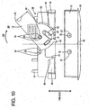
- a lever-type connector according to this embodiment is constructed such that a first housing 56 and a second housing 57 are connected and separated by a lever 12 arranged in the first housing 56. It should be noted that sides of the two housings 10, 11 to be connected are referred to as front sides in the following description.
- the second housing 57 projects outward from a wall surface of a fixed member 63 and is a waiting-side housing.
- One or more, preferably a pair of (preferably substantially cylindrical) cam pins 25 are formed at positions of the outer surface of the lateral (upper) wall of the second housing 57 near the front end. Both cam pins 25 are arranged at positions preferably substantially transversely symmetrical with respect to an axis of symmetry 39 passing the widthwise or transverse center of the second housing 57 and/or substantially in parallel with connecting directions of the two housings 10, 11.
- a larger-diameter portion 27 enlarged in radially outward directions of the cam pin 25 is formed at the upper end of each cam pin 25.
- the first housing 56 preferably is to be connected with one or more wires 19 forming a wiring harness and is a harness-side or movable-side housing.
- a pair of (preferably substantially cylindrical) supporting shafts 38 are formed at positions of the outer surface of the lateral (upper) wall of the first housing 56 near the rear end. Both supporting shafts 38 are arranged at positions substantially transversely symmetrical with respect to the axis of symmetry 39 passing the widthwise or transverse center of the first housing 56 and/or substantially in parallel with the connecting directions of the two housings 10, 11.
- One or more, preferably a pair of protrusions 58 project laterally (to left and/or right) from the upper or distal end of each supporting shaft 38.
- a (preferably substantially rectangular) notch 40 is so formed substantially in the vicinity of the transverse center of a front side of the lateral (upper) wall of the first housing 56 as to extend substantially backward from the front edge and to be preferably substantially transversely symmetrical with respect to the axis of symmetry 39.
- One or more, preferably a pair of lateral (left and/or right) plate-like pressing portions 59 are provided at the (preferably substantially opposite) outer lateral (left and/right) side(s) of the notch 40. Both pressing portions 59 preferably have a substantially rectangular shape narrow and long along transverse direction, and are arranged substantially in parallel with the lateral (upper) wall of the first housing 56.
- a notch is formed at a rear-left corner of the right pressing portion 59 to prevent the interference with the lever 12, and an eave or slanted portion 60 for pressing a bulging portion 62 of the lever 12 from above as described later is formed.
- a notch is formed at a rear-right corner of the left pressing portion 59 to prevent the interference with the lever 12, and another eave or slanted portion 60 for pressing the bulging portion 62 of the lever 12 from above is formed.
- the lever 12 is provided with a side plate 42 preferably substantially having a comb-shape obtained by cutting off a rear-end area of the peripheral portion of a circle when viewed from above, and a (preferably substantially rectangular) operable portion 43 projecting outwardly or laterally (to right) from the lateral (right) end of the side plate 42.
- the lever 12 preferably substantially is vertically symmetrical as a whole.
- This lever 12 is mounted or mountable on the right supporting shaft 38 in FIG. 10 on the first housing 56 and is movable (rotatable or pivotable) between a standby position SP (as a preferred first position) and a connected position CP (as a preferred second position). Reference is made to a state where the lever 12 is at the connected position (see FIG. 10 ) concerning forward and backward directions and transverse direction in the description of the lever 12.
- a shaft hole or recess 44 having a shape conforming to the shape of the supporting shafts 38 is formed to vertically penetrate the center of the side plate 42, and the aforementioned supporting shaft 38 is or may be at least partly inserted into this shaft hole 44.
- a round hole (not shown) is formed outside the shaft hole 44 so as to let the protrusions 58 of the supporting shaft 38 escape when the lever 12 is rotated or operated.
- a can groove 26 preferably substantially oblique to both circumferential direction and radial directions substantially centered on the shaft hole 44 is formed before or near the shaft hole 44 in the side plate 42.
- a cam-pin receiving portion 64 for receiving the larger-diameter portion 27 of the cam pin 25 is formed at the upper edge of the cam groove 26 over at least part of, preferably over the substantially entire length of the cam groove 26.
- a locking piece 41 for holding the lever 12 at the standby position SP is formed at a position of the side plate 42 at the left side of the shaft hole 44.
- This locking piece 41 preferably is substantially in the form of a plate narrow and long in forward and backward directions FBD, and has the front end thereof supported on the side plate 42 while projecting backward.
- This resilient locking piece 41 is resiliently deformable upward and downward (or outwardly and inwardly or towards and away from the housing 10) with the base end (front end) as a supporting point.
- the rear end of the locking piece 41 is engaged with the rear edge of the notch 40 when the lever 12 is at the standby position SP.
- the arcuate bulging portion 62 substantially concentric with the side plate 42 preferably is formed to bulge radially outward at the front edge of the side plate 42.
- the upper surface of the bulging portion 62 is lowered with respect to that of the side plate 42, thereby forming a step.
- a (preferably substantially hook-shaped) engaging portion 53 projecting radially outward from the lateral edge of the side plate 42 is formed at the lateral (left) side of the entrance of the cam groove 26 of the side plate 42.
- the rear edge of the engaging portion 53 preferably is engageable with the lateral (left) cam pin 25 of FIG. 11 with the lever 12 held or positioned at the connected position CP.
- the engaging portion 53 is engageable with the cam pin 25 on which the shaft hole 44 of the lever 12 is currently not arranged with the lever 12 positioned at the connected position CP.
- the second housing 57 is lightly fitted into the first housing 56, causing the lateral (right) cam pin 25 in FIG. 10 to at least partly enter the entrance of the cam groove 26. Then, an unillustrated unlocking portion comes substantially into contact with the locking piece 41, which is then resiliently deformed upward or outward by moving onto the unlocking portion, whereby the locking piece 41 is disengaged from the notch 40 to permit the lever 12 to move in an operating direction OD (rotate pr pivot in clockvvise direction of FIG. 10 ).
- the lateral (right) cam pin 25 is guided substantially along the cam groove 26, whereby the two housings 56, 57 are pulled toward each other along the connecting directions CD thereof.
- the engaging portion 53 comes into engagement with the other lateral (left) cam pin 25 of FIG. 11 as shown in FIG. 11 , whereby the left cam pin 25 receives a force acting in a direction (outward direction or upward direction in FIG. 11 ) substantially along the connecting direction CD of the second housing 57 via the engaging portion 53. In this way, the posture of the second housing 57 can be corrected to a proper one.
- the connecting operation is completed with the two housings 56, 57 held in their substantially proper postures by pushing the operable portion 43 in this state.
- the movement in an opposite direction (counterclockwise rotation) of the lever 12 in FIG. 11 can be prevented by one or more unillustrated lever holding means.
- any further forward movements of the two housings 56, 57 are prevented by the contact of the front ends of the cam pins 25 with the rear edge of the notch 40.
- the lever 12 is mounted in the first housing 56 such that the lever 12 is mounted on the one lateral (right) supporting shaft 38 in FIG. 10 and operated in the operating direction OD (rotated in clockwise direction) from the standby position SP toward the connected position CP and the operable portion 43 is located at the lateral (right) end when the lever 12 is at the connected position CP.
- the lever 12 may also be mounted on the other lateral (left) supporting shaft 38 and mounted in the first housing 56 in a posture transversely reversed from the above one in this embodiment.
- the engaging portion 53 is engageable with the one lateral (right) cam pin 25.
- the lever 12 is mounted in the first housing 56 such that the lever 12 is rotated in a direction substantially opposite to the above operating direction OD (in counterclockwise direction) from the standby position toward the connected position and the operable portion 43 is located at the opposite lateral (left) end when the lever 12 is at the connected position. Since a procedure of connecting the two housings 56, 57 by operating (rotating) the lever 12 from the standby position to the connected position after the lever 12 is mounted into the first housing 56 is transversely symmetrical with the above-described procedure, the functions are not described. According to this embodiment, the lever 12 is engaged with the cam pin 25 not engaged with the cam groove 26 when the lever 12 is at the connected position CP. Thus, as compared to a case where the locking projections 52 are separately provided, the construction of the second housing 57 can be simplified.
Description
- The present invention relates to a connector and connector assembly of the movable member type, particularly to a lever type connector and connector assembly.
- Document
GB 2 322 242 A - Document
JP 2001 326024 A - Document
US 2003/0162427 A1 discloses a lever-type connector assembly with mating female and male connectors. The female connector has a lever with a cam plate and a resilient lock that is deformable within the plate of the cam plate. The resilient lock engages a receiving portion on the female connector for holding the lever at an initial position. - Document
US 2003/0199185 A1 discloses a connector with first and second housings and a wire cover which is mounted to cover the upper surface of the second housing. A lever is supported rotatably on the second housing and has cam grooves that engage follower pins on the first housing. The two housings are connected by rotating the lever to an end position. - Document
US 2002/0004326 A1 discloses a connector support mechanism which comprises a female connector and a male connector. A cam lever formed with a cam groove which guides a boss protruding from the female connector is turnably pivoted by the male connector. In a state in which the boss is inserted into the cam groove, if the cam lever turns, the female connector and the male connector are fitted to each other. - A lever-type connector is known from
Japanese Unexamined Patent Publication No. 2001-326024 - However, according to the above construction, immediately before the two housings are properly connected, the lateral end of the female hosing in the vicinity of the operable portion of the lever is pushed in the direction along the connecting direction of the female housing as the lever is rotated. Thus, there are cases where a connected state of the lateral portion in the vicinity of the operable portion of the lever precedes that of a lateral portion at a side opposite to the operable portion of the lever, resulting in an inclined posture.
- The present invention was developed in view of the above problem and an object thereof is to allowing to correct the posture of one housing in the process of connecting the two housings.
- This object is solved according to the invention by the features of the independent claims. Preferred embodiments of the invention are subject of the dependent claims.
- According to the invention, there is provided a connector of the movable member type, in particular of the lever type, in which a movable member such as a lever having an operable portion at or near a side plate is movably mounted in or on or to a housing, the movable member comprising at least one cam member engageable with at least one mating cam member formed on a mating housing so that it can be guided along the cam member as the movable member is operated, thereby connecting the housing with the mating housing, wherein:
- an engaging portion engageable with a locking projection formed on the mating housing is formed at an end of the movable member substantially opposite to the operable portion, and
- immediately before the housing is properly connected with the mating housing, the locking projection is engaged with the engaging portion and receives a force acting in a direction along a connecting direction of the mating housing via the engaging portion as the movable member is operated.
- Accordingly, if the connected state of the lateral end portion of the housing located in the vicinity of the operation portion of the movable member precedes that of the lateral end portion opposite to the operable portion of the operable member immediately before the two housings are properly connected, the locking projection receives the force acting in the direction substantially along the connecting direction of the mating housing by being brought into engagement with the engaging portion formed at the side of the movable member opposite to the operable portion. Thus, the posture of the housing can be corrected, enabling the two housings to be connected in their substantially proper postures.
- According to a preferred embodiment of the invention, the movable member is rotatably or pivotably mounted to the housing and the operable portion of the movable member is located at a lateral end portion of the housing radially distanced from an axis of rotation of the movable member.
- Preferably, the movable member is operated in a direction along a connecting direction of the housing immediately before the two housings are properly connected.
- According to a further preferred embodiment of the invention, there is provided a lever-type connector in which a lever having an operable portion at a leading-end side of a side plate is rotatably mounted in a first housing, a cam pin formed on a second housing is guided along a cam groove formed in the side plate as the lever is rotated, thereby connecting the two housings, and the operable portion of the lever is located at a lateral end portion of the first housing radially distanced from an axis of rotation of the lever and is operated in a direction along a connecting direction of the first housing immediately before the two housings are properly connected, wherein:
- a locking projection is formed on the second housing,
- an engaging portion engageable with the locking projection is formed at an end of the lever opposite to the operable portion, and
- immediately before the two housings are properly connected, the locking projection is engaged with the engaging portion and receives a force acting in a direction along a connecting direction of the second housing via the engaging portion as the lever is rotated.
- Accordingly, if the connected state of the lateral end portion of the first housing located in the vicinity of the operation portion of the lever precedes that of the lateral end portion opposite to the operable portion of the lever immediately before the two housings are properly connected, the locking projection receives the force acting in the direction along the connecting direction of the second housing by being brought into engagement with the engaging portion formed at the side of the lever opposite to the operable portion. Thus, the posture of the first housing can be corrected, enabling the two housings to be connected in their proper postures.
- Preferably, the housing or first housing is a harness-side housing to be connected with wires forming a wiring harness, and the mating housing or second housing is a waiting-side housing to be disposed on a fixed member.
- Further preferably, at least one guiding wall extending substantially in the connecting directions of the two housings is formed at a position substantially corresponding to the locking projection of the mating housing or second housing in or near an end surface of the housing or first housing at a side to be connected with the m<ting housing or second housing, and comes or can come substantially into sliding contact with the locking projection during a connecting operation of the two housings.
- Accordingly, the locking projection of the mating/second housing guides or can substantially guide the connecting and separating operation of the two housings by coming substantially into sliding contact with the guiding wall formed in the first housing. Therefore, the two housings can be connected and separated in their substantially proper postures.
- Further preferably, the movable member, particularly the lever, is mountable to or in or on the (first) housing in two transversely substantially symmetrical postures, and/or a pair of locking projections are formed at two transversely symmetrical positions with respect to the second housing.
- Accordingly, operation efficiency in connecting the two housings can be improved since the mounting posture of the movable member, particularly the lever, can be freely selected in the case where there is any restriction on an operating space of the movable member, particularly the lever.
- Still further preferably, at least one pair of supporting shafts are formed on the housing at two substantially transversely symmetrical positions with respect to the housing,
the movable member is rotatably or pivotably mounted on one of the supporting shafts, thereby being made mountable in two substantially transversely symmetrical postures with respect to the housing. - Further preferably, the operable portion of the movable member mounted on the one of the supporting shafts is located at a side of the one supporting shaft opposite to the other supporting shaft immediately before the two housings are properly connected.
- Most preferably, a pair of supporting shafts are formed on the first housing at two transversely symmetrical positions with respect to the first housing,
the lever is rotatably mounted on one of the supporting shafts, thereby being made mountable in two transversely symmetrical postures with respect to the first housing,
the operable portion of the lever mounted on the one of the supporting shafts is located at a side of the one supporting shaft opposite to the other supporting shaft immediately before the two housings are properly connected,
a pair of cam pins are formed on the second housing at positions corresponding to the cam groove of the lever in the respective states where the lever is mounted on the one or the other of the supporting shafts, and
out of the two cam pins, the one not engaged with the cam groove serves as the locking projection. - Accordingly, since the cam pin not engaged with the cam groove can serve as the locking projection, the construction of the second housing can be simplified as compared to a case where the locking projection is separately provided.
- According to the invention, there is further provided a connector assembly comprising a connector of the movable member type according to the invention or a preferred embodiment thereof and a mating connector having the mating connector housing, the locking projection being formed on the mating housing.
- According to a preferred embodiment of the invention, a pair of mating cam members are formed on the mating housing at positions corresponding to the cam member of the movable member in the respective states where the movable member is mounted on the one or the other of the supporting shafts.
- Preferably, out of the two mating cam members, the one not engaged with the cam member serves as the locking projection.
- These and other objects, features and advantages of the present invention will become more apparent upon reading of the following detailed description of preferred embodiments and accompanying drawings. It should be understood that even though embodiments are separately described, single features thereof may be combined to additional embodiments.
-
FIG. 1 is a plan view in section showing a properly connected state of a lever-type connector according to a first embodiment, -
FIG. 2 is a side view in section showing a male housing and a female housing according to the first embodiment, -
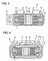
FIG. 3 is a front view of the male housing according to the first embodiment, -
FIG. 4 is a front view of the female housing according to the first embodiment, -
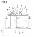
FIG. 5 is a plan view of the female housing according to the first embodiment, -
FIG. 6 is a plan view in section of the female housing and a plan view of the male housing according to the first embodiment in a state where a lever is located at a standby position, -
FIG. 7 is a plan view in section of the female housing and a plan view of the male housing according to the first embodiment showing an initial state of a connecting operation of the two housings, -
FIG. 8 is a plan view in section of the female housing and a plan view of the male housing according to the first embodiment showing a state progressed from the connected state ofFIG. 7 , -
FIG. 9 is a plan view in section of the female housing and a plan view of the male housing according to the first embodiment showing a state immediately before the two housings are properly connected, -
FIG. 10 is a plan view of a first housing and a second housing showing a state where a lever is located at a standby position in a lever-type connector according to a second embodiment, and -
FIG. 11 is a plan view showing a properly connected state of the lever-type connector according to the second embodiment. - A first preferred embodiment of the present invention is described with reference to
FIGS. 1 to 9 . A connector having a movable operable member, preferably a lever, according to this embodiment is constructed such that a female housing 10 (corresponding to a preferred first housing) and a male housing 11 (corresponding to a preferred second housing) are or can be connected and separated (or the connection and separation thereof may be assisted) by means of a movable member, preferably comprising a lever, to be provided in or on thefemale housing 10. The female andmale housings housings FIG. 2 concerning vertical direction. - The
male housing 11 is made e.g. of a synthetic resin material and preferably is a waiting-side housing arranged or arrangeable on an unillustrated fixed member as shown inFIGS. 2 and3 . Areceptacle 13 having an open front side is formed at or near a front side of themale housing 11, and aterminal accommodating portion 15 for accommodating one or more male terminal fittings 14 is formed behind or adjacent to thereceptacle 13. - One or more
mounting lock portions 16 used to mount themale housing 11 on the fixed member are formed on the outer lateral (left and/or right) side surface(s) of theterminal accommodating portion 15 inFIG. 1 . As shown inFIG. 2 , one ormore cavities 17 extending substantially in forward and backward directions FBD are formed in theterminal accommodating portion 15, and the male terminal fittings 14 are to be at least partly inserted into therespective cavities 17 from an insertion side, preferably substantially from behind. Each male terminal fitting 14 is comprised of amain portion 18 and abarrel portion 20 provided behind themain portion 18 and to be connected (preferably crimped or folded or bent into connection) with awire 19, wherein a (preferably substantially narrow and long)tab piece 21 extends substantially forward from or near the front end of themain portion 18. A (preferably substantially cantilever-shaped) lockingportion 22 resiliently deformable and preferably extending substantially forward projects at an inner wall of eachcavity 17. This lockingportion 22 is or can be resiliently engaged with the terminal fitting 14, preferably with themain portion 18, to retain the male terminal fitting 14. With the male terminal fitting 14 at least partly accommodated in thecavity 17, thetab piece 21 at least partly projects into thereceptacle 13. Aretainer 23 preferably is mountable into a front-end portion of theterminal accommodating portion 15 to (preferably doubly) lock the male terminal fittings 14. A waterproof resilient plug orwaterproof rubber plug 24 preferably is so at least partly fitted on a rear part of thebarrel portion 20 as to at least partly surround thebarrel portion 20 together with an insulation coating of thewire 19, wherein sealing preferably is to be provided between thewire 19 and the inner circumferential surface of thecavity 17 by the resilient close contact between the outer circumferential surface of the waterproof resilient/rubber plug 24 and the inner circumferential surface of thecavity 17. - As shown in
FIGS. 2 and3 , a substantiallycylindrical cam pin 25 projecting laterally or upward (or in a direction at an angle different from 0° or 180°, preferably substantially normal to the connecting direction CD) is formed at a position at or near the front end of the outer surface of the lateral (upper) wall of thereceptacle 13 preferably substantially in the transverse center inFIG. 3 , and is engageable with acam groove 26 of a lever 12 (as a preferred movable member) to be described later. A larger-diameter portion 27 enlarged in one or more radially outward directions of thecam pin 25 is formed at the upper or distal end of thecam pin 25, and a (preferably substantially vertical) separation of thecam groove 26 and thecam pin 25 is prevented by the engagement of a cam-pin receiving portion 64 of thelever 12 to be described later with the bottom or inner edge of the larger-diameter portion 27. One or more, preferably a pair of guidingribs 28 extending substantially in forward and backward directions FBD project upward or outward at the (preferably substantially opposite) lateral (left and/or right) side(s) of thecam pin 25, and substantially guides the connecting and separating operations of the twohousings more receiving portions 29 of thefemale housing 10 to be described later. A slanted or roundedsurface 30 inclined down or inwardly toward the front is formed at or near the front end of each guidingrib 28 in order to facilitate a movement of a partial orfirst locking piece 41 of thelever 12 to be described later onto the guidingrib 28. A phantom straight line 39 (seeFIG. 1 ) passing the widthwise and/or transverse center of themale housing 11 and substantially in parallel with the connecting directions CD of the twohousings symmetry 39, and the guidingribs 28 preferably are transversely symmetrical with respect to this axis ofsymmetry 39. - The
female housing 10 is made e.g. of a synthetic resin material and, and aninner tube portion 32 in which one or more, preferably a plurality ofcavities 17 extending substantially in forward and backward directions FBD are formed substantially side by side along width direction is formed inside anouter tube portion 31 at one or more stages as shown inFIGS. 2 and4 . A female terminal fitting 33 is to be at least partly inserted into eachcavity 17 from an inserting side, preferably substantially from behind, to be locked and retained by a lockingportion 22 formed in or at thecavity 17. Each female terminal fitting 33 is comprised of a (preferably substantially rectangular)tube portion 34 which preferably is substantially in the form of a rectangular tube and into which thetab piece 21 of the male terminal fitting 14 at least partly accommodated in themale housing 11 is to be at least partly inserted, and a wire connection portion (preferably comprising a barrel portion 20) provided behind or adjacent to the (rectangular)tube portion 34 and to be connected (preferably substantially crimped or bent or folded into connection) with awire 19. A resiliently deformable resilient contact piece (not shown) is formed in the (rectangular)tube portion 34 to be resiliently brought into contact with thetab piece 21 at least partly inserted into the (rectangular)tube portion 34. A waterproof resilient plug orwaterproof rubber plug 24 is so fitted on or to a rear part of thebarrel portion 20 as to at least partly surround thebarrel portion 20 preferably together with an insulation coating of thewire 19, wherein sealing is provided between thewire 19 and the inner circumferential surface of thecavity 17 by the resilient close contact between the outer circumferential surface of the waterproof resilient/rubber plug 24 and the inner circumferential surface of thecavity 17. Further, a (preferably substantially cap-shaped)retainer 23 preferably is to be mounted on or to a front-end portion of theinner tube portion 32 in thefemale housing 10 to (preferably doubly) lock the femaleterminal fittings 33. In this way, thefemale housing 10 is connected with thewires 19 forming a wiring harness and serves or may serve as a harness-side or movable side housing. - The
receptacle 13 of the aforementionedmale housing 11 is at least partly insertable into a clearance between theinner tube portion 32 and theouter tube portion 31. Atubular seal ring 35, preferably made of resilient material such as rubber, is to be mounted on or to the outer circumferential surface of theinner tube portion 32 near an intermediate part (preferably near or at a substantially middle part) of theinner tube portion 32 with respect to forward and backward directions FBD. Sealing preferably is provided between themale housing 11 and thefemale housing 10 by the resilient close contact between one or more (e.g. three)lips 36 circumferentially formed on the outer circumferential surface of theseal ring 35 over at least part, preferably over the substantially entire circumference and the inner circumferential surface of thereceptacle 13 of themale housing 11 as shown. - A lever accommodating space 37 (as a preferred movable member accommodating space) for at least partly accommodating the movable member, preferably the
lever 12, is so formed at a lateral (upper) side of theouter tube portion 31 as to penetrate substantially in forward and backward directions FBD. A (preferably substantially cylindrical) supportingshaft 38 extends downward from the ceiling wall of thislever accommodating space 37. Thelever accommodating space 37 preferably is substantially transversely symmetrically formed with respect to the axis ofsymmetry 39 passing the center axis of the supportingshaft 38. As shown inFIG. 6 , a (preferably substantially rectangular)notch 40 is so formed in the bottom or inner wall of thelever accommodating space 37 as part of theouter tube portion 31 as to extend substantially backward from the front edge. One or more (preferably substantially rectangular) receivingportions 29 substantially continuous with the (preferably substantially opposite) lateral (left and/or right) wall(s) of thenotch 40 preferably substantially via quarter arc(s) project inward preferably substantially transversely symmetrically with respect to the axis ofsymmetry 39 at the rear side of thenotch 40. A lockingpiece 41 of thelever 12 to be described later is or can be engaged with one of the receivingportions 29 in a standby state of thelever 12 to be described later. - As shown in
FIG. 1 , the lever 12 (as the preferred movable member) is made e.g. of a synthetic resin material and provided with aside plate 42 preferably substantially having such a comb-shape obtained by cutting off a rear-end area of the peripheral portion of a circle when viewed from above, and anoperable portion 43 bulging out laterally (slightly to left) from the rear end of theside plate 42 at a lateral (left) side inFIG. 1 . Thelever 12 preferably is substantially vertically symmetrical (or symmetrical with respect to an axis or plane substantially normal to the axis of rotation) as a whole. Thislever 12 is so mounted at least partly in thelever accommodating space 37 of thefemale housing 10 as to be rotatable or pivotable between a standby position SP (as a preferred first position) and a connected position CP (as a preferred second position). Here, the standby position SP (first position) refers to a position of thelever 12 where the entrance of thecam pin 25 formed on themale housing 11 is permitted to at least partly enter acam groove 26 formed in theside plate 42 of the lever 12 (seeFIG. 6 ), whereas the connected position CP (second position) referred to as a position of thelever 12 where the twohousings FIG. 1 ). Reference is made to a state where thelever 12 is at the connected position CP concerning forward and backward directions FBD and transverse direction in the description of thelever 12. - A shaft hole or
recess 44 is formed to vertically penetrate the center of theside plate 42, and the aforementioned supportingshaft 38 is or can be at least partly inserted into thisshaft hole 44. Thecam groove 26 oblique to both circumferential direction and radial directions (or having a spiral-like shape) substantially centered on theshaft hole 44 is formed before theshaft hole 44 in theside plate 42. Thecampin receiving portion 64 for receiving the larger-diameter portion 27 of thecam pin 25 is formed at the upper edge of thecam groove 26 over the entire length of thecam groove 26. The lockingpiece 41 for holding or positioning thelever 12 at the standby position SP is formed at a position of theside plate 42 at the lateral (right) side of theshaft hole 44. The lockingpiece 41 preferably is substantially in the form of a plate narrow and long in forward and backward directions FBD, and has the front end thereof supported on theside plate 42 while projecting backward. Thisresilient locking piece 41 is resiliently deformable upward and downward or inwardly and outwardly or towards and away from thehousing 10 with the base end (front end) as a supporting point. The rear end of the lockingpiece 41 is engaged with the aforementioned receivingportion 29 when thelever 12 is at the standby position SP. Further, when thelever 12 is at the standby position SP (first position), the entrance of thecam groove 26 preferably is located substantially on the axis ofsymmetry 39 passing the supportingshaft 38 of thelever 12. - A resilient lock piece 45 (preferably substantially in the form of a narrow and long plate extending substantially in forward and backward directions FBD) is formed at the lateral (left) rear side of the
side plate 42. Thisresilient lock piece 45 preferably is a cantilever extending substantially backward from its front end, and is resiliently deformable upward and downward or inwardly and outwardly or towards and away from thehousing 10. One or more vertically or outwardly projectinglock projections 46 are formed at a position in the vicinity of a substantial center of theresilient lock piece 45 with respect to forward and backward directions FBD. Theresilient lock piece 45 holds or positions thelever 12 at the connected position CP (second position) preferably by the engagement of theabove lock projection 46 and one of a pair ofreturn preventing portions 47 preferably substantially transversely symmetrically formed in thelever accommodating space 37 with respect to thelever accommodating space 37 with thelever 12 located at the connected position CP. - One or more steps dented inwardly with respect to the thickness of the
side plate 42 preferably are formed in areas of both upper and lower surfaces of theside plate 42 where the front end of theresilient lock piece 45 is formed, and these one or more steps serve as one or more holding steps 48 for holding thelever 12 at the standby position SP by coming into engagement with thereturn preventing portion 47 with thelever 12 located at the standby position SP. - As shown in
FIG. 1 , one or more supportingshaft escaping grooves 49 for letting the supportingshaft 38 escape upon mounting thelever 12 in thefemale housing 10 are so formed by recessing the respective surface(s), preferably both lateral (upper and lower) surfaces, of theside plate 42 inwardly with respect to the thickness direction TD of theside plate 42 as to extend from a position slightly more outward than theshaft hole 44 toward the entrance of thecam groove 26. A slantedsurface 30 for facilitating a movement of the supportingshaft 38 beyond a portion of theside plate 42 between the supportingshaft escaping groove 49 and theshaft hole 44 is formed at an end of each supporting-shaft escaping groove 49 toward theshaft hole 44. Further, as shown inFIG. 6 , one or more return-preventingportion escaping grooves 50 for letting thereturn preventing portion 47 upon mounting thelever 12 in thefemale housing 10 are so formed by recessing both respective surface(s), the lateral (upper and lower) surfaces of theside plate 42 inwardly with respect to the thickness direction TD of theside plate 42 as to extend forward from a position slightly before the holding steps 48 inFIG. 6 . Further, a slanted orbent surface 30 for facilitating a movement of the return-preventingportion 47 beyond a portion of theside plate 42 between the holdingstep 48 and the return-preventingportion escaping groove 50 is formed at or near the rear edge of each return-preventingportion escaping groove 50 inFIG. 6 . Further, one ormore recesses 51 dented inwardly with respect to the thickness direction TD of theside plate 42 of thelever 12 are formed at a right rear end of thelever 12 inFIG. 1 for letting the return-preventingportion 47 escape upon mounting thelever 12 into thefemale housing 10. A side wall of eachrecess 51 is or may be engaged with the return-preventingportion 47 to hold thelever 12 at the connected position CP when thelever 12 is at the connected position CP. - As shown in
FIGS. 3 and6 , one or more, preferably a pair of lockingprojections 52 projecting upward or outward are formed preferably substantially at transversely symmetrical positions with respect to a phantom axis (axis of symmetry 39) extending substantially along forward and backward directions FBD and passing the center axis of thecam pin 25, these positions preferably being located near the lateral (left and right) sides of the front end of the upper surface of thereceptacle 13 of themale housing 11. The lockingprojections 52 preferably are substantially trapezoidal in plan view (refer e.g. toFIG. 6 ). The rear edges of the lockingprojections 52 are substantially straight along transverse direction, and are brought or bringable substantially into contact with the rear edge of an engagingportion 53 of thelever 12 to be described later. The outer side surfaces of the lockingprojections 52 with respect to the transverse direction of themale housing 11 are substantially straight along forward and backward directions FBD, and can be brought substantially into sliding contact with the inner surfaces of guidingwalls 55 of thefemale housing 10 to be described later. The inner side surfaces of the lockingprojections 52 with respect to the transverse direction of themale housing 11 preferably have a substantially arcuate contour substantially in conformity with the lateral edge of thelever 12 so as to let this lateral edge escape. - On the other hand, the engaging
portion 53 is so formed as to project outward from the lateral edge of theside plate 42 at an end (right end inFIG. 1 ) of thelever 12 substantially opposite to theoperable portion 43. The rear edge of the engagingportion 53 is substantially straight along transverse direction, and can come substantially into alignment with the rear edges of theaforementioned locking projections 52. One or more escapingholes 54 for letting the lockingprojections 52 of themale housing 11 escape are so formed in an end surface of the upper side of theouter tube portion 31 at a side to be connected with themale housing 11 preferably as to be substantially symmetrical with respect to the axis ofsymmetry 39 and extend substantially in forward and backward directions FBD at positions substantially corresponding to the locking projection 52 (seeFIGS. 1 and4 ). The inner side walls of the escapingholes 54 come substantially into sliding contact with the outer side walls of the lockingprojections 52 upon connecting and separating the twohousings walls 55 for guiding the connecting and separating operations of the twohousings - Subsequently, the constructions of the respective members during the connecting operation of the two
housings housings FIG. 6 , thelever 12 provided in thefemale housing 10 is so held at the standby position SP (first position) as not to be operable (movable or rotatable or pivotable) by the engagement of the lockingpiece 41 with the lateral (right) receivingportion 29 and the engagement of the holdingstep 48 with the lateral (left)return preventing portion 47. In this state, the entrance of thecam groove 26 of thelever 12 is faced substantially forward or substantially along the connecting direction CD to enable thecam pin 25 of themale housing 11 to at least partly enter thecam groove 26. - Subsequently, in a state shown in
FIG. 7 reached by moving the twohousings cam pin 25 is located at or near the entrance of thecam groove 26 of thelever 12. At this time, the guidingribs 28 are located in thenotch 40, and thelocking piece 41 is resiliently deformed upward or outward by moving onto the lateral (right) guidingrib 28. This causes thelocking piece 41 and the lateral (right) receivingportion 29 to be disengaged, whereby thelever 12 is operable or movable (rotatable or pivotable) e.g. in counterclockwise direction ofFIG. 7 from the standby position SP. The outer side surfaces of the guidingribs 28 with respect to transverse direction come substantially into sliding contact with the inner edges of the receivingportions 29 to guide the connecting operation of the twohousings - Subsequently, during a movement of the
lever 12 to a state shown inFIG. 8 preferably by being rotated or pivoted, thecam pin 25 moves toward the back side of thecam groove 26 while being guided substantially along thecam groove 26 of thelever 12, and the female andmale housings lock projection 46 of thelever 12 moves onto the lateral (left)return preventing portion 47, causing theresilient lock piece 45 to be resiliently deformed upward or outward. - When the
lever 12 is operated or moved (rotated or pivoted) to the state shown inFIG. 1 , the twohousings lever 12 in this state is referred to as the connected position CP (second position). At this time, thelock projection 46 of theresilient lock piece 45 of thelever 12 preferably is engaged with the lateral (left)return preventing portion 47 to prevent the movement (clockwise rotation) of thelever 12, and therecess 51 is engaged with the lateral (right)return preventing portion 47 to prevent the substantially opposite movement (counterclockwise rotation) of thelever 12. Further, the lateral (right) lockingprojection 52 receives a force in the connecting direction CD of themale housing 11 by the engagingportion 53, whereby the postures of the twohousings housings projection 52 and the rear edges of the escapingholes 54 and the contact of the front edges of the guidingribs 28 and the rear edge of thenotch 40. - Next, functions and effects of this embodiment are described. Upon mounting the
lever 12 into or to thefemale housing 10, the ceiling wall of thelever accommodating space 37 is deformed to curve and thelever 12 held in the substantially same orientation (posture) as at the standby position SP is at least partly inserted into thelever accommodating space 37 from an inserting side, preferably substantially from behind. At this time, the lateral (left)return preventing portion 47 inFIG. 1 comes to be located in the return preventingportion escaping groove 50 of thelever 12, the substantially opposite lateral (right)return preventing portion 47 inFIG. 1 comes to be located in therecess 51 of thelever 12, and the supportingshaft 38 comes to be located in the supportingshaft escaping groove 49 after passing thecam groove 26 of thelever 12. This can reduce connection resistance between thelever 12 and thefemale housing 10 at the time of mounting thelever 12. In this way, connection resistance between thelever 12 and thefemale housing 10 at the time of mountinglever 12 can be reduced. At this time, thereturn preventing portions 47 and the supportingshaft 38 can easily move substantially onto the corresponding parts since the return preventingportion escaping grooves 50 and the supportingshaft escaping grooves 49 are formed with the slanted or rounded surfaces 30. - When the
lever 12 is further inserted to the back side of thelever accommodating space 37, the supportingshaft 38 is at least partly fitted into theshaft hole 44 after moving onto the slantedsurface 30 provided at the rear edge of the supportingshaft escaping groove 49. At this time, the leftreturn preventing portion 47 inFIG. 1 is resiliently at least partly restored after moving onto the slantedsurface 30 provided at the rear edge of the return preventingportion escaping groove 50, thereby coming substantially into contact with the holdingstep 48 preferably substantially from behind, with the result that thelever 12 is prevented from moving (e.g. rotating in clockwise direction ofFIG. 1 ). Further, the lockingpiece 41 comes substantially into contact with the lateral (right) receivingportion 29 to prevent thelever 12 from moving in an substantially opposite direction (e.g. rotating in counterclockwise direction ofFIG. 1 ). In this way, thelever 12 is held or positioned at the standby position SP while being preferably prevented from moving (e.g. rotating in both forward and reverse directions). - If the
receptacle 13 of themale housing 11 is lightly fitted into thefemale housing 10 in this state, thecam pin 25 at least partly enters the entrance of thecam groove 26 as shown inFIG. 7 . At this time, the one ormore locking projections 52 come to be located substantially in the respective escapingholes 54 and the outer side surfaces of the lockingprojections 52 come substantially into sliding contact with the guidingwalls 55 of the escapingholes 54, thereby guiding the connecting operation of the twohousings ribs 28 are inserted into thenotch 40 and the front end of theright guiding rib 28 comes substantially into contact with the lockingpiece 41, whereby the lockingpiece 41 is resiliently deformed upward or outward by moving onto the lateral (right) guidingrib 28. Thus, the lockingpiece 41 and the lateral (right) receivingportion 29 are disengaged, enabling thelever 12 to move (rotate in counterclockwise direction ofFIG. 7 ). At this time, the lockingpiece 41 can easily move onto the lateral (right) guidingrib 28 since the slantedsurface 30 is formed. - If the
lever 12 is operated (e.g. rotated counterclockwise) about the supportingshaft 38 by pushing theoperable portion 43 in this state, a position shown inFIG. 8 is or can be reached. At this time, the twohousings cam pin 25 is guided along thecam groove 26. In this state, theresilient lock piece 45 starts being resiliently deformed upward or outward by thelock projection 46 moving onto the lateral (left)return preventing portion 47. Further, the connecting operation of the twohousings ribs 28 with the inner edges of the receivingportions 29. - When the connecting operation further progresses to reach a position shown in
FIG. 9 , i.e. a state immediately before the twohousings operable portion 43 of thelever 12 is located at the lateral (left) rear side of thefemale housing 10 inFIG. 9 . If theoperable portion 43 of thelever 12 is operated or pushed in this state, thefemale housing 10 receives a force in the connecting direction CD (downward direction inFIG. 9 ) thereof. Then, the connected state precedes at the lateral (left) side of thefemale housing 10 inFIG. 9 , although this state is not shown in detail, with the result that thefemale housing 10 may assume an inclined posture (e.g. inclined down to left inFIG. 9 ) in some cases. - If the
operable portion 43 is further operated or pushed in the above state, the engagingportion 53 comes into engagement with the lateral (right) lockingprojection 52 as shown inFIG. 1 , whereby the lateral (right) lockingprojection 52 receives a force acting along the connecting direction CD (upward direction inFIG. 1 ) of themale housing 11 via the engagingportion 53. Then, at the lateral (right) side of thefemale housing 10 in the inclined posture (e.g. inclined down to left inFIG. 9 ), a force acts in such a direction as to insert themale housing 11, thereby substantially correcting or tending to correct the inclined posture of thefemale housing 10 towards or to a substantially proper one. The connecting operation is completed with the twohousings operable portion 43 in this state. In the resulting state, theresilient lock piece 45 is resiliently at least partly restored to engage thelock projection 46 thereof with the lateral (left)return preventing portion 47 inFIG. 1 , thereby preventing thelever 12 from moving (e.g. rotating in clockwise direction ofFIG. 1 ). Further, the rightreturn preventing portion 47 inFIG. 1 and the side wall of therecess 51 are engaged to prevent thelever 12 from moving (e.g. rotating in counterclockwise direction ofFIG. 1 ). Any further forward movements of the twohousings projections 52 with the rear edges of the escapingholes 54 and by the contact of the front edges of the guidingribs 28 with the rear edge of thenotch 40. - Upon separating the two
housings resilient lock piece 45 is resiliently deformed upward or outward by having the rear end thereof pushed up from below e.g. by finger or a jig or the like. Then, thelock projection 46 is disengaged from the lateral (left)return preventing portion 47, thereby permitting the movement (rotation) of thelever 12 at the connected position CP toward the standby position SP. Thelever 12 is moved or operated (rotated in clockwise direction ofFIG. 1 ) by holding theoperable portion 43 while being kept unlocked. Then, thecam pin 25 is guided substantially along thecam groove 26 and the twohousings lever 12 reaches the standby position SP, the twohousings FIG. 7 . In or close to this state, the twohousings - Although the
lever 12 is mounted in thefemale housing 10 such that thelever 12 is operable or movable in an operation direction OD (rotated or pivoted in counterclockwise direction) from the standby position SP toward the connected position CP and theoperable portion 43 is located at the lateral (left) end of thefemale housing 10 when thelever 12 is at the connected position CP in the above description, thelever 12 can also be mounted in thefemale housing 10 in a posture transversely reversed from the above one in this embodiment. As means for realizing this, thelever 12 preferably has a substantially vertically symmetrical shape; the entrance of thecam groove 26 is located substantially on the axis ofsymmetry 39 passing the supportingshaft 38 of thelever 12 with thelever 12 held at the standby position SP; thereturn preventing portions 47 are arranged at two substantially transversely symmetrical positions with respect to the axis ofsymmetry 39; the lockingprojections 52 are arranged at two substantially transversely symmetrical positions with respect to the axis ofsymmetry 39; the escapingholes 54 are arranged at two substantially transversely symmetrical positions with respect to the axis ofsymmetry 39; the guidingribs 28 are arranged at two substantially transversely symmetrical positions with respect to the axis ofsymmetry 39; and/or the receivingportions 29 project inward substantially transversely symmetrically with respect to the axis ofsymmetry 39. - If the
lever 12 is mounted in the posture transversely reversed from the above one, thelever 12 is mounted in thefemale housing 10 such that thelever 12 is operated in an opposite direction OOD to the above operating direction (rotated in clockwise direction) from the standby position SP toward the connected position CP and theoperable portion 43 is located at the opposite lateral (right) end when thelever 12 is at the connected position CP. Since a procedure of connecting the twohousings lever 12 from the standby position SP to the connected position CP after thelever 12 is mounted into thefemale housing 10 is transversely symmetrical with the above-described procedure, the functions are not described. - As described above, according to this embodiment, if the connected state of the lateral side of the
female housing 10 located in the vicinity of theoperable portion 43 of thelever 12 precedes that of the lateral side opposite to theoperable portion 43 of thelever 12 immediately before the twohousings projection 52 receives a force in the direction along the connecting direction CD of themale housing 11 by the engagement with the engagingportion 53 formed at the side of thelever 12 opposite to theoperable portion 43. Therefore, the posture of thefemale housing 10 is corrected, enabling the twohousings - Further, the locking
projections 52 of thefemale housing 10 guide the connecting and separating operations of the twohousings walls 55 formed in themale housing 11, whereby the twohousings - Furthermore, since one
lever 12 can be mounted into thefemale housing 10 in either one of two postures transversely symmetrical with respect to the axis ofsymmetry 39, the operation operability (rotating or pivoting operability) of thelever 12 can be improved by suitably selecting the mounted posture of thelever 12 depending on a situation where the lever-type connector is arranged. - Accordingly, to provide a connector of the movable member type, preferably of the lever-type capable of correcting the posture of one housing in the process of connecting two housings, immediately before a
female housing 10 in which alever 12 as a preferred movable member is provided and amale housing 11 are properly connected, anoperable portion 43 of thelever 12 is located at a lateral end of thefemale housing 10 and operated in a direction substantially along a connecting direction CD of themale housing 11. Themale housing 11 is formed with lockingprojections 52, and an engagingportion 53 engageable with one lockingprojection 52 is formed at an end of thelever 12 opposite to theoperable portion 43. Immediately before the twohousings projection 52 is engaged with the engagingportion 53 and receives a force acting in the direction substantially along the connecting direction CD of themale housing 11 as thelever 12 is operated or rotated. In this way, the posture of thefemale housing 10 is corrected, enabling the twohousings - Next, a second preferred embodiment of the present invention is described with reference to
FIGS. 10 and11 . A lever-type connector according to this embodiment is constructed such that afirst housing 56 and asecond housing 57 are connected and separated by alever 12 arranged in thefirst housing 56. It should be noted that sides of the twohousings - The
second housing 57 projects outward from a wall surface of a fixedmember 63 and is a waiting-side housing. One or more, preferably a pair of (preferably substantially cylindrical) cam pins 25 are formed at positions of the outer surface of the lateral (upper) wall of thesecond housing 57 near the front end. Both cam pins 25 are arranged at positions preferably substantially transversely symmetrical with respect to an axis ofsymmetry 39 passing the widthwise or transverse center of thesecond housing 57 and/or substantially in parallel with connecting directions of the twohousings diameter portion 27 enlarged in radially outward directions of thecam pin 25 is formed at the upper end of eachcam pin 25. - The
first housing 56 preferably is to be connected with one ormore wires 19 forming a wiring harness and is a harness-side or movable-side housing. A pair of (preferably substantially cylindrical) supportingshafts 38 are formed at positions of the outer surface of the lateral (upper) wall of thefirst housing 56 near the rear end. Both supportingshafts 38 are arranged at positions substantially transversely symmetrical with respect to the axis ofsymmetry 39 passing the widthwise or transverse center of thefirst housing 56 and/or substantially in parallel with the connecting directions of the twohousings protrusions 58 project laterally (to left and/or right) from the upper or distal end of each supportingshaft 38. - A (preferably substantially rectangular)
notch 40 is so formed substantially in the vicinity of the transverse center of a front side of the lateral (upper) wall of thefirst housing 56 as to extend substantially backward from the front edge and to be preferably substantially transversely symmetrical with respect to the axis ofsymmetry 39. One or more, preferably a pair of lateral (left and/or right) plate-likepressing portions 59 are provided at the (preferably substantially opposite) outer lateral (left and/right) side(s) of thenotch 40. Bothpressing portions 59 preferably have a substantially rectangular shape narrow and long along transverse direction, and are arranged substantially in parallel with the lateral (upper) wall of thefirst housing 56. A notch is formed at a rear-left corner of theright pressing portion 59 to prevent the interference with thelever 12, and an eave or slantedportion 60 for pressing a bulgingportion 62 of thelever 12 from above as described later is formed. Similarly, a notch is formed at a rear-right corner of theleft pressing portion 59 to prevent the interference with thelever 12, and another eave or slantedportion 60 for pressing the bulgingportion 62 of thelever 12 from above is formed. - As shown in
FIG. 10 , thelever 12 is provided with aside plate 42 preferably substantially having a comb-shape obtained by cutting off a rear-end area of the peripheral portion of a circle when viewed from above, and a (preferably substantially rectangular)operable portion 43 projecting outwardly or laterally (to right) from the lateral (right) end of theside plate 42. Thelever 12 preferably substantially is vertically symmetrical as a whole. Thislever 12 is mounted or mountable on theright supporting shaft 38 inFIG. 10 on thefirst housing 56 and is movable (rotatable or pivotable) between a standby position SP (as a preferred first position) and a connected position CP (as a preferred second position). Reference is made to a state where thelever 12 is at the connected position (seeFIG. 10 ) concerning forward and backward directions and transverse direction in the description of thelever 12. - A shaft hole or
recess 44 having a shape conforming to the shape of the supportingshafts 38 is formed to vertically penetrate the center of theside plate 42, and the aforementioned supportingshaft 38 is or may be at least partly inserted into thisshaft hole 44. A round hole (not shown) is formed outside theshaft hole 44 so as to let theprotrusions 58 of the supportingshaft 38 escape when thelever 12 is rotated or operated. A can groove 26 preferably substantially oblique to both circumferential direction and radial directions substantially centered on theshaft hole 44 is formed before or near theshaft hole 44 in theside plate 42. A cam-pin receiving portion 64 for receiving the larger-diameter portion 27 of thecam pin 25 is formed at the upper edge of thecam groove 26 over at least part of, preferably over the substantially entire length of thecam groove 26. A lockingpiece 41 for holding thelever 12 at the standby position SP is formed at a position of theside plate 42 at the left side of theshaft hole 44. This lockingpiece 41 preferably is substantially in the form of a plate narrow and long in forward and backward directions FBD, and has the front end thereof supported on theside plate 42 while projecting backward. Thisresilient locking piece 41 is resiliently deformable upward and downward (or outwardly and inwardly or towards and away from the housing 10) with the base end (front end) as a supporting point. The rear end of the lockingpiece 41 is engaged with the rear edge of thenotch 40 when thelever 12 is at the standby position SP. The arcuate bulgingportion 62 substantially concentric with theside plate 42 preferably is formed to bulge radially outward at the front edge of theside plate 42. The upper surface of the bulgingportion 62 is lowered with respect to that of theside plate 42, thereby forming a step. - A (preferably substantially hook-shaped) engaging
portion 53 projecting radially outward from the lateral edge of theside plate 42 is formed at the lateral (left) side of the entrance of thecam groove 26 of theside plate 42. The rear edge of the engagingportion 53 preferably is engageable with the lateral (left)cam pin 25 ofFIG. 11 with thelever 12 held or positioned at the connected position CP. In other words, the engagingportion 53 is engageable with thecam pin 25 on which theshaft hole 44 of thelever 12 is currently not arranged with thelever 12 positioned at the connected position CP. - Next, functions and effects of this embodiment are described. After the supporting
shaft 38 is at least partly inserted into theshaft hole 44 of thelever 12 preferably while the shape of theshaft hole 44 is substantially aligned with the positions of theprotrusions 58 of the supportingshaft 38, thelever 12 is operated (rotated) to the standby position SP (seeFIG. 10 ). Then, the leading end of the lockingpiece 41 comes substantially into contact with the rear edge of thenotch 40, and thelever 12 is so held as not to move (rotate or pivot) in either forward or reverse direction by unillustrated holding means. At this time, the lateral (right) pressingportion 59 is located above the bulgingportion 62 to prevent an upward displacement of thelever 12. - In this state, the
second housing 57 is lightly fitted into thefirst housing 56, causing the lateral (right)cam pin 25 inFIG. 10 to at least partly enter the entrance of thecam groove 26. Then, an unillustrated unlocking portion comes substantially into contact with the lockingpiece 41, which is then resiliently deformed upward or outward by moving onto the unlocking portion, whereby the lockingpiece 41 is disengaged from thenotch 40 to permit thelever 12 to move in an operating direction OD (rotate pr pivot in clockvvise direction ofFIG. 10 ). - If the
lever 12 is moved in the operating direction OD (rotated or pivoted in clockwise direction) about the lateral (right) supportingshaft 38 by pushing theoperable portion 43 in this state, the lateral (right)cam pin 25 is guided substantially along thecam groove 26, whereby the twohousings portion 53 comes into engagement with the other lateral (left)cam pin 25 ofFIG. 11 as shown inFIG. 11 , whereby theleft cam pin 25 receives a force acting in a direction (outward direction or upward direction inFIG. 11 ) substantially along the connecting direction CD of thesecond housing 57 via the engagingportion 53. In this way, the posture of thesecond housing 57 can be corrected to a proper one. The connecting operation is completed with the twohousings operable portion 43 in this state. In the resulting state, the movement in an opposite direction (counterclockwise rotation) of thelever 12 inFIG. 11 can be prevented by one or more unillustrated lever holding means. Further, any further forward movements of the twohousings notch 40. - In the above description, the
lever 12 is mounted in thefirst housing 56 such that thelever 12 is mounted on the one lateral (right) supportingshaft 38 inFIG. 10 and operated in the operating direction OD (rotated in clockwise direction) from the standby position SP toward the connected position CP and theoperable portion 43 is located at the lateral (right) end when thelever 12 is at the connected position CP. However, thelever 12 may also be mounted on the other lateral (left) supportingshaft 38 and mounted in thefirst housing 56 in a posture transversely reversed from the above one in this embodiment. At this time, the engagingportion 53 is engageable with the one lateral (right)cam pin 25.
If thelever 12 is mounted in the posture transversely reversed from the above one, thelever 12 is mounted in thefirst housing 56 such that thelever 12 is rotated in a direction substantially opposite to the above operating direction OD (in counterclockwise direction) from the standby position toward the connected position and theoperable portion 43 is located at the opposite lateral (left) end when thelever 12 is at the connected position. Since a procedure of connecting the twohousings lever 12 from the standby position to the connected position after thelever 12 is mounted into thefirst housing 56 is transversely symmetrical with the above-described procedure, the functions are not described.
According to this embodiment, thelever 12 is engaged with thecam pin 25 not engaged with thecam groove 26 when thelever 12 is at the connected position CP. Thus, as compared to a case where the lockingprojections 52 are separately provided, the construction of thesecond housing 57 can be simplified. - The present invention is not limited to the above described and illustrated embodiments. For example, the following embodiments are also embraced by the technical scope of the present invention as defined by the claims.
- (1) Although the
lever 12 is plate-like in the first embodiment, the present invention is not limited thereto. Thelever 12 may be substantially gate-shaped or substantially U-shaped by connecting ends of a pair ofside plates 42 by anoperable portion 43 or may be L- or V-shaped. In such a case, the posture of thefemale housing 10 being connected can be corrected not only at the upper side, but also at the lower side. Thus, the postures of the twohousings - (2) Although the
lever 12 is mountable in two transversely reversed postures with respect to the axis ofsymmetry 39 in the first embodiment, the present invention is not limited thereto and thelever 12 is mountable only in one transverse posture. Depending on cases, only one lockingprojection 52 may be formed. - (3) Although the escaping
holes 54 and the guidingwalls 55 for letting the lockingprojections 52 escape and guiding the lockingprojections 52 are formed in the end surface of thefemale housing 10 at the side to be connected with themale housing 11 in the first embodiment, the present invention is not limited thereto, and the material of thefemale housing 10 may be removed at positions corresponding to the lockingprojections 52 to let the lockinggrooves 52 escape. - (4) Although the first housing is the
female housing 10 and the second housing is themale housing 11 in the first embodiment, the present invention is not limited thereto and the first housing may be themale housing 11 and the second housing may be thefemale housing 10. - (5) Although the
male housing 11 is fixed to the fixed member by means of the mountinglock portions 16 in the first embodiment, the present invention is not limited thereto and themale housing 11 may project from a wall surface of the fixed member. - (6) Although in the above embodiments the operable member is in the form of a lever rotatably or pivotably provided on the first connector housing it shold be understood that the invention is equally applicable to movable members having different operation paths such as a slider having a substantially linear displacement path or to any other movable member having different moving paths such as bent, elliptic or the like paths or combined paths.
-
- 10 ...
- female housing (first housing)
- 11 ...
- male housing (second housing)
- 12 ...
- lever
- 19 ...
- wire
- 25 ...
- cam pin
- 26 ...
- cam groove
- 38 ...
- supporting shaft
- 42 ...
- side plate
- 43 ...
- operable portion
- 52 ...
- locking projection
- 53 ...
- engaging portion
- 55 ...
- guiding wall
- 56 ...
- first housing
- 57 ...
- second housing
Claims (11)
- A connector of the movable member type in which a movable member (12) having an operable portion (43) at or near a side plate (42) is movably mounted in or on a housing (10; 56), the movable member (12) comprising at least one cam member (26) engageable with at least one mating cam member (25) formed on a mating housing (11; 57) so that it can be guided along the cam member (26) as the movable member (12) is operated, thereby connecting the housing (10; 56) with the mating housing (11; 57), wherein:an engaging portion (53) engageable with a locking projection (52) is formed on the mating housing (11; 57), andimmediately before the housing (10; 56) is properly connected with the mating housing (11; 57), the locking projection (52) is engaged with the engaging portion (53) and receives a force via the engaging portion (53) as the movable member (12) is operated;characterized in, thatthe engaging portion (53) is formed at an end of the movable, member (12) substantially opposite to the operable portion (43), and thatthe force acts in a direction along a connecting-direction (CD) of the mating housing (11; 57).
- A connector of the movable member type according to claim 1, wherein the movable member (12) is rotatably or pivotably mounted to the housing (10; 56) and the operable portion (43) of the movable member (12) is located at a lateral end portion of the housing (10; 56) radially distanced from an axis (38) of rotation of the movable member (12).
- A connector of the movable member type according to one or more of the preceding claims, wherein the movable member (12) is operated in a direction (OD) along a connecting direction (CD) of the housing (10; 56) immediately before the two housings (10, 11; 56, 57) are properly connected.
- A connector of the movable member type according to one or more of the preceding claims, wherein the housing (10; 56) is a harness-side housing to be connected with wires forming a wiring harness, and/or the mating housing (11; 57) is a waiting-side housing to be disposed on a fixed member.
- A connector of the movable member type according to one or more of the preceding claims, wherein at least one guiding wall (55) extending substantially in the connecting directions (CD) of the two housings (10, 11; 56, 57) is formed at a position substantially corresponding to the locking projection (52) of the mating housing (11; 57) in or near an end surface of the housing (10; 56) at a side to be connected with the mating housing (11; 57), and can come substantially into sliding contact with the locking projection (52) during a connecting operation of the two housings (10, 11; 56, 57).
- A connector of the movable member type according to one or more of the preceding claims, wherein the movable member (12) is mountable in or to the housing (10; 56) in two transversely symmetrical postures, and a pair of locking projections (52) are formed at two substantially transversely symmetrical positions with respect to the mating housing (10; 56).
- A connector of the movable member type according to claim 6, wherein:at least one pair of supporting shafts (38) are formed on the housing (10; 56) at two substantially transversely symmetrical positions with respect to the housing (10; 56),the movable member (12) is rotatably mounted on one of the supporting shafts (38), thereby being made mountable in two substantially transversely symmetrical postures with respect to the housing (10; 56).
- A connector of the movable member type according to claim 7, wherein the operable portion (43) of the movable member (12) mounted on the one of the supporting shafts (38) is located at a side of the one supporting shaft (38) opposite to the other supporting shaft (38) immediately before the two housings (10, 11; 56, 57) are properly connected.
- A connector assembly comprising a connector of the movable member type according to one or more of the preceding claims and a mating connector having the mating connector housing (11; 57), the locking projection (52) being formed on the mating housing (11: 57).
- A connector assembly of the movable member type according to claim 9, wherein a pair of mating cam members (25) are formed on the mating housing (11; 57) at positions corresponding to the cam members (26) of the movable member (12) in the respective states where the movable member (12) is mounted on the one or the other of the supporting shafts.
- A connector assembly of the movable member type according to claim 10, wherein out of the two mating cam members (25), the one not engaged with the cam member (26) serves as the locking projection (52).
Applications Claiming Priority (1)
| Application Number | Priority Date | Filing Date | Title |
|---|---|---|---|
| JP2005175262A JP4492449B2 (en) | 2005-06-15 | 2005-06-15 | Lever type connector |
Publications (2)
| Publication Number | Publication Date |
|---|---|
| EP1734619A1 EP1734619A1 (en) | 2006-12-20 |
| EP1734619B1 true EP1734619B1 (en) | 2008-12-31 |
Family
ID=36781483
Family Applications (1)
| Application Number | Title | Priority Date | Filing Date |
|---|---|---|---|
| EP06010429A Active EP1734619B1 (en) | 2005-06-15 | 2006-05-19 | A connector and connector assembly of the movable member type |
Country Status (5)
| Country | Link |
|---|---|
| US (2) | US7300294B2 (en) |
| EP (1) | EP1734619B1 (en) |
| JP (1) | JP4492449B2 (en) |
| CN (1) | CN100517880C (en) |
| DE (1) | DE602006004504D1 (en) |
Families Citing this family (36)
| Publication number | Priority date | Publication date | Assignee | Title |
|---|---|---|---|---|
| JP4395784B2 (en) * | 2006-03-03 | 2010-01-13 | 住友電装株式会社 | Lever type connector |
| JP2008027691A (en) * | 2006-07-20 | 2008-02-07 | Yazaki Corp | Lever manufacturing method of lever fitting connector |
| EP1903641B1 (en) * | 2006-09-21 | 2010-03-31 | Molex Incorporated | Lever type electrical connector |
| JP4966622B2 (en) * | 2006-10-12 | 2012-07-04 | 矢崎総業株式会社 | Lever type connector |
| JP4248001B2 (en) * | 2006-10-19 | 2009-04-02 | 古河電気工業株式会社 | Lever connector |
| KR20080073145A (en) * | 2007-02-05 | 2008-08-08 | 타이코에이엠피 주식회사 | A connector with a lever |
| JP2008218119A (en) * | 2007-03-02 | 2008-09-18 | Sumitomo Wiring Syst Ltd | Lever-type connector |
| JP4960853B2 (en) * | 2007-12-20 | 2012-06-27 | 矢崎総業株式会社 | Lever type connector |
| JP4575423B2 (en) * | 2007-12-26 | 2010-11-04 | 日本航空電子工業株式会社 | connector |
| JP2009158430A (en) * | 2007-12-28 | 2009-07-16 | Sumitomo Wiring Syst Ltd | Lever-type connector |
| JP2009170160A (en) * | 2008-01-11 | 2009-07-30 | Sumitomo Wiring Syst Ltd | Lever-type connector |
| DE102009056184B4 (en) * | 2008-12-22 | 2012-10-04 | Sumitomo Wiring Systems, Ltd. | Interconnects |
| JP2011071015A (en) * | 2009-09-28 | 2011-04-07 | Sumitomo Wiring Syst Ltd | Lever type connector |
| JP5534501B2 (en) * | 2009-10-09 | 2014-07-02 | 矢崎総業株式会社 | Lever type connector |
| JP5257340B2 (en) * | 2009-12-02 | 2013-08-07 | 住友電装株式会社 | Lever type connector |
| JP5035361B2 (en) * | 2010-02-04 | 2012-09-26 | 住友電装株式会社 | Lever type connector |
| JP5723700B2 (en) * | 2011-07-01 | 2015-05-27 | 矢崎総業株式会社 | Lever fitting type connector |
| JP5728310B2 (en) * | 2011-07-01 | 2015-06-03 | 矢崎総業株式会社 | Lever fitting type connector |
| JP5913874B2 (en) * | 2011-09-12 | 2016-04-27 | 矢崎総業株式会社 | Power circuit breaker |
| JP5229405B2 (en) * | 2012-02-22 | 2013-07-03 | 住友電装株式会社 | Lever type connector |
| EP2680374B1 (en) * | 2012-06-29 | 2020-01-22 | Aptiv Technologies Limited | Connection device |
| JP5937046B2 (en) * | 2013-09-04 | 2016-06-22 | ヒロセ電機株式会社 | Connector device having locking means and connector used therefor |
| JP2016096095A (en) * | 2014-11-17 | 2016-05-26 | 住友電装株式会社 | Lever type connector |
| JP6332074B2 (en) * | 2015-02-16 | 2018-05-30 | 住友電装株式会社 | Lever type connector |
| JP6499023B2 (en) * | 2015-06-12 | 2019-04-10 | 矢崎総業株式会社 | connector |
| JP6492030B2 (en) * | 2016-05-30 | 2019-03-27 | 矢崎総業株式会社 | connector |
| JP6441866B2 (en) * | 2016-09-21 | 2018-12-19 | 矢崎総業株式会社 | Lever type connector |
| JP6587595B2 (en) * | 2016-10-31 | 2019-10-09 | 矢崎総業株式会社 | Lever type connector |
| US9948030B1 (en) * | 2017-09-15 | 2018-04-17 | Phoenix Contact Development and Manufacturing, Inc. | Lever-type electrical connector body and related electrical connector assembly |
| JP2019091609A (en) * | 2017-11-14 | 2019-06-13 | 住友電装株式会社 | connector |
| JP2019091610A (en) * | 2017-11-14 | 2019-06-13 | 住友電装株式会社 | connector |
| JP6944410B2 (en) * | 2018-06-06 | 2021-10-06 | 住友電装株式会社 | Lever type connector |
| JP6933190B2 (en) * | 2018-06-06 | 2021-09-08 | 住友電装株式会社 | Lever type connector |
| JP2020027784A (en) * | 2018-08-17 | 2020-02-20 | 矢崎総業株式会社 | Lever type connector |
| JP2020202053A (en) * | 2019-06-07 | 2020-12-17 | 矢崎総業株式会社 | Lever type connector |
| CN117650397B (en) * | 2024-01-30 | 2024-04-02 | 深圳市锦凌电子有限公司 | Electric connector with electrifying locking function and terminal structure |
Family Cites Families (13)
| Publication number | Priority date | Publication date | Assignee | Title |
|---|---|---|---|---|
| GB2322242B (en) * | 1994-09-06 | 1998-10-21 | Sumitomo Wiring Systems | Divisional connector |
| JP3278042B2 (en) * | 1996-09-02 | 2002-04-30 | 住友電装株式会社 | Lever connector |
| JP3726639B2 (en) * | 2000-05-16 | 2005-12-14 | 住友電装株式会社 | Lever type connector |
| DE10131936B4 (en) * | 2000-07-03 | 2004-05-19 | Yazaki Corp. | Self-locking lever-type connector |
| JP2002025693A (en) * | 2000-07-11 | 2002-01-25 | Yazaki Corp | Connector support mechanism |
| JP3562448B2 (en) * | 2000-07-13 | 2004-09-08 | 住友電装株式会社 | Lever type connector |
| JP3603760B2 (en) * | 2000-08-11 | 2004-12-22 | 住友電装株式会社 | Lever type connector |
| JP3829615B2 (en) * | 2000-10-31 | 2006-10-04 | 住友電装株式会社 | connector |
| DE10232969B4 (en) * | 2001-07-23 | 2012-08-23 | Sumitomo Wiring Systems, Ltd. | Connector with locking lever |
| US6551118B2 (en) * | 2001-07-26 | 2003-04-22 | Molex Incorporated | Lever type electrical connector |
| JP3987736B2 (en) * | 2002-02-26 | 2007-10-10 | 住友電装株式会社 | Lever type connector |
| JP3987737B2 (en) * | 2002-02-26 | 2007-10-10 | 住友電装株式会社 | Lever type connector |
| JP3882111B2 (en) * | 2002-04-22 | 2007-02-14 | 住友電装株式会社 | Lever type connector |
-
2005
- 2005-06-15 JP JP2005175262A patent/JP4492449B2/en active Active
-
2006
- 2006-05-19 DE DE602006004504T patent/DE602006004504D1/en active Active
- 2006-05-19 EP EP06010429A patent/EP1734619B1/en active Active
- 2006-06-14 US US11/452,746 patent/US7300294B2/en active Active
- 2006-06-15 CN CNB2006100925192A patent/CN100517880C/en active Active
-
2007
- 2007-11-26 US US11/986,720 patent/US7520765B2/en active Active
Also Published As
| Publication number | Publication date |
|---|---|
| DE602006004504D1 (en) | 2009-02-12 |
| CN100517880C (en) | 2009-07-22 |
| US7520765B2 (en) | 2009-04-21 |
| US7300294B2 (en) | 2007-11-27 |
| JP4492449B2 (en) | 2010-06-30 |
| CN1881704A (en) | 2006-12-20 |
| US20060286834A1 (en) | 2006-12-21 |
| JP2006351331A (en) | 2006-12-28 |
| US20080081498A1 (en) | 2008-04-03 |
| EP1734619A1 (en) | 2006-12-20 |
Similar Documents
| Publication | Publication Date | Title |
|---|---|---|
| EP1734619B1 (en) | A connector and connector assembly of the movable member type | |
| EP2075880B1 (en) | Lever-type connector, connector assembly and connecting method | |
| EP1936756B1 (en) | A connector of the movable member type | |
| EP1981128B1 (en) | A lever-type connector and connector assembly | |
| EP1742302B1 (en) | A connector, connector assembly and assembling method therefor | |
| US7214078B2 (en) | Connector and connector assembly | |
| EP1715551B1 (en) | A connector and a method of assembling it | |
| US7670157B2 (en) | Lever connector | |
| EP1830436B1 (en) | A connector, connector assembly and assembling method | |
| US7445474B2 (en) | Lever-type connector and lever-type connector assembly | |
| EP1689046A1 (en) | A shielded connector | |
| US20080009186A1 (en) | Connector | |
| US7063548B2 (en) | Connector and connector assembly | |
| EP1830435B1 (en) | A lever-type connector and connector assembly | |
| US8215970B2 (en) | Connector | |
| KR101400581B1 (en) | Electric connector | |
| EP1801925B1 (en) | A connector | |
| US6863551B2 (en) | Connector, set of connectors and method of connecting a connector | |
| US6623286B2 (en) | Lever-type connector | |
| EP1826877B1 (en) | Electrical connector | |
| EP1445838B1 (en) | A connector and a connector assembly | |
| US6837733B2 (en) | Connector with cover retained at partly assembled position and movable to properly assembled position | |
| EP1801926B1 (en) | A connetor and connector assembly | |
| EP2317609B1 (en) | Connector, series of connectors and method of assembling it | |
| EP1995828B1 (en) | A lever-type connector and an assembling method therefor |
Legal Events
| Date | Code | Title | Description |
|---|---|---|---|
| PUAI | Public reference made under article 153(3) epc to a published international application that has entered the european phase |
Free format text: ORIGINAL CODE: 0009012 |
|
| 17P | Request for examination filed |
Effective date: 20060601 |
|
| AK | Designated contracting states |
Kind code of ref document: A1 Designated state(s): AT BE BG CH CY CZ DE DK EE ES FI FR GB GR HU IE IS IT LI LT LU LV MC NL PL PT RO SE SI SK TR |
|
| AX | Request for extension of the european patent |
Extension state: AL BA HR MK YU |
|
| AKX | Designation fees paid |
Designated state(s): DE |
|
| GRAP | Despatch of communication of intention to grant a patent |
Free format text: ORIGINAL CODE: EPIDOSNIGR1 |
|
| GRAS | Grant fee paid |
Free format text: ORIGINAL CODE: EPIDOSNIGR3 |
|
| GRAA | (expected) grant |
Free format text: ORIGINAL CODE: 0009210 |
|
| AK | Designated contracting states |
Kind code of ref document: B1 Designated state(s): DE |
|
| REF | Corresponds to: |
Ref document number: 602006004504 Country of ref document: DE Date of ref document: 20090212 Kind code of ref document: P |
|
| RIN2 | Information on inventor provided after grant (corrected) |
Inventor name: SAKURAI, TOSHIKAZU Inventor name: FUJII, MASAYASU Inventor name: FUKATSU, YUKIHIRO |
|
| PLBE | No opposition filed within time limit |
Free format text: ORIGINAL CODE: 0009261 |
|
| STAA | Information on the status of an ep patent application or granted ep patent |
Free format text: STATUS: NO OPPOSITION FILED WITHIN TIME LIMIT |
|
| 26N | No opposition filed |
Effective date: 20091001 |
|
| REG | Reference to a national code |
Ref country code: DE Ref legal event code: R084 Ref document number: 602006004504 Country of ref document: DE |
|
| P01 | Opt-out of the competence of the unified patent court (upc) registered |
Effective date: 20230517 |
|
| PGFP | Annual fee paid to national office [announced via postgrant information from national office to epo] |
Ref country code: DE Payment date: 20230331 Year of fee payment: 18 |