EP1734266A1 - Fastening device - Google Patents
Fastening device Download PDFInfo
- Publication number
- EP1734266A1 EP1734266A1 EP05728787A EP05728787A EP1734266A1 EP 1734266 A1 EP1734266 A1 EP 1734266A1 EP 05728787 A EP05728787 A EP 05728787A EP 05728787 A EP05728787 A EP 05728787A EP 1734266 A1 EP1734266 A1 EP 1734266A1
- Authority
- EP
- European Patent Office
- Prior art keywords
- fastening
- clip
- shape
- driving
- pin
- Prior art date
- Legal status (The legal status is an assumption and is not a legal conclusion. Google has not performed a legal analysis and makes no representation as to the accuracy of the status listed.)
- Granted
Links
Images



Classifications
-
- F—MECHANICAL ENGINEERING; LIGHTING; HEATING; WEAPONS; BLASTING
- F16—ENGINEERING ELEMENTS AND UNITS; GENERAL MEASURES FOR PRODUCING AND MAINTAINING EFFECTIVE FUNCTIONING OF MACHINES OR INSTALLATIONS; THERMAL INSULATION IN GENERAL
- F16B—DEVICES FOR FASTENING OR SECURING CONSTRUCTIONAL ELEMENTS OR MACHINE PARTS TOGETHER, e.g. NAILS, BOLTS, CIRCLIPS, CLAMPS, CLIPS OR WEDGES; JOINTS OR JOINTING
- F16B5/00—Joining sheets or plates, e.g. panels, to one another or to strips or bars parallel to them
- F16B5/02—Joining sheets or plates, e.g. panels, to one another or to strips or bars parallel to them by means of fastening members using screw-thread
-
- F—MECHANICAL ENGINEERING; LIGHTING; HEATING; WEAPONS; BLASTING
- F16—ENGINEERING ELEMENTS AND UNITS; GENERAL MEASURES FOR PRODUCING AND MAINTAINING EFFECTIVE FUNCTIONING OF MACHINES OR INSTALLATIONS; THERMAL INSULATION IN GENERAL
- F16B—DEVICES FOR FASTENING OR SECURING CONSTRUCTIONAL ELEMENTS OR MACHINE PARTS TOGETHER, e.g. NAILS, BOLTS, CIRCLIPS, CLAMPS, CLIPS OR WEDGES; JOINTS OR JOINTING
- F16B2200/00—Constructional details of connections not covered for in other groups of this subclass
- F16B2200/77—Use of a shape-memory material
-
- Y—GENERAL TAGGING OF NEW TECHNOLOGICAL DEVELOPMENTS; GENERAL TAGGING OF CROSS-SECTIONAL TECHNOLOGIES SPANNING OVER SEVERAL SECTIONS OF THE IPC; TECHNICAL SUBJECTS COVERED BY FORMER USPC CROSS-REFERENCE ART COLLECTIONS [XRACs] AND DIGESTS
- Y10—TECHNICAL SUBJECTS COVERED BY FORMER USPC
- Y10S—TECHNICAL SUBJECTS COVERED BY FORMER USPC CROSS-REFERENCE ART COLLECTIONS [XRACs] AND DIGESTS
- Y10S411/00—Expanded, threaded, driven, headed, tool-deformed, or locked-threaded fastener
- Y10S411/02—Temperature modification
Definitions
- the present invention relates to a fastening device.
- a joint retaining member in which among a shaft, a header that fits on one end of the shaft and a nut that fits on the other end of the shaft, at least any one of the members is formed of a shape memory alloy, so that the joint retaining member can release the mechanical binding by shape change of the shape memory alloy in accordance with heating or cooling applied to this member (for example, refer to Patent Document 1).
- a fastening member that is formed of a shape memory alloy molded in such a shape that fastening can be released under heating, in which the fastening member is secondarily processed into a shape capable of fastening at temperatures at which it is not reverted to the memorized shape, and a microwave absorption material or infrared absorption material is coated on the surface of the fastening member or provided inside the fastening member (for example, refer to Patent Document 2).
- the joint retaining member or the fastening member since the main body of the joint retaining member or the fastening member is formed of a shape memory alloy and has a relatively complicated shape, improving the efficiency of heat transfer during heating is difficult, and problems arise such as accumulation of the energy required until releasing the mechanical binding and fastening. Also, since the joint retention strength and fastening strength are restricted according to the material characteristics of the shape memory alloy, there is a risk that the desired strength cannot be ensured.
- the present invention was achieved in view of the aforementioned circumstances, and has as its object to provide a fastening device that can reduce the energy required for fastening release and readily release the fastening, and can ensure the desired fastening strength.
- the fastening device is provided with a fastening member that fixedly fastens fastened members, and a driving member that is capable of releasing a fastening state of the fastening member by applying a driving force to a moving portion provided in the fastening member to drive it, wherein the driving member is formed of a shape memory alloy, and the driving force is a restoring force of the shape-memory alloy to its memory shape.
- the fastening device of this constitution providing the fastening device with the fastening member and the driving member can prevent the shapes of the members from becoming complicated compared to the case of, for example, integrating the fastening member and the driving member, and can improve the versatility of the fastening device. Also, by forming the driving member, which is capable of releasing the fastening state of the fastening member, with a shape memory alloy, the fastening member may be formed of a suitable construction material that can ensure the desired fastening strength so that the fastened members can be fixedly fastened in a suitable manner.
- presupposing the aforementioned invention is provided with an energizing means that energizes the driving member, wherein the driving member is reverted to the memory shape by being energized by the energizing means.
- the driving member which is formed of a shape memory alloy, is restored from a deformed state to the memory shape when the temperature rises to the transformation point of the shape memory alloy or higher by resistance heat generation from energization from the energizing means, with the moving portion being driven by the restoring force at this time to release the fastening state of the fastening member.
- the fastening member is provided with a pin member that is attached to the fastened members, and a clip member that holds the pin member, the clip member includes two pinching members formed as the moving portion to be turnable about a turning axis, with the pin member being held so as to be pinched from both sides by the two pinching members, and the driving member releases the fastening state of the fastening member by turning the pinching members of the clip member about the turning axis.
- the fastened members to which the pin member is attached are fixedly fastened by the clip member that pinches the pin member and a nut member that is attached to one end of the pin member.
- the driving member releases the pinched state of the pin member by turning the two pinching members constituting the clip member in opposite directions about the turning axis so as to mutually separate, and by separating the pin member from the clip member releases the fastening state of the fastening member.
- the fastening member is provided with a pin member that is attached to the fastened members, and a clip member that holds the pin member, the clip member includes a notch portion in which the pin member, which is the moving portion, is attached, the pin member is held by an inside wall surface of the notch portion so as to be sandwiched from both sides, the driving member presses the pin member toward an outside of the notch portion of the clip member, and the fastening state of the fastening member is released by separating the pin member from the notch portion.
- the fastened members to which the pin member is attached are fixedly fastened by the clip member that pinches the pin member and a nut member that is attached to one end of the pin member.
- the driving member separates the pin member from the notch portion by pressing the pin member, which is attached to the notch portion of the clip member, to the outside, thereby releasing the fastening state of the fastening member.
- the clip member includes a holding member that holds the driving member.
- the driving member is held at the clip member, whereby due to the restoring force when the shape memory alloy of the driving member reverts from the deformed shape to the memory shape, the two pinching members constituting the clip member are turned about the turning axis, and by pressing toward the outside the pin member, which is attached to the notch portion of the clip member, can release the fastening state of the fastening member.
- the clip member includes a restriction member that restricts driving of the moving portion.
- the fastening device of this constitution when the shape memory alloy of the driving member held in the clip member reverts from the deformed shape to the memory shape, excessive turning of the two pinching members constituting the clip member, and excessive deformation of the moving member in the direction that presses the pin member, which is attached to the notch portion of the clip member, outward can be prevented.
- the pin member includes either one of a mutually fitting concave portion and convex portion
- the clip member includes the other one of the concave portion and convex portion
- the fastening device of this constitution when the pin member is held in the clip member, the pin member and the clip member are firmly fixed, and the desired fastening strength can be ensured by the fitting of either one of the concave portion and convex portion provided in the pin member and either one of the concave portion and convex portion provided in the clip member.
- the driving member is formed-of a shape memory alloy in a coil shape or a U-shape, and being deformed in the fastening state of the fastening member so that a distance between two predetermined positions of the shape memory alloy becomes closer than a distance in the memory shape.
- the fastening device of this constitution when the shape memory alloy of the driving member reverts from the deformed shape to the memory shape, the distance between the two predetermined positions of the shape memory alloy increases, whereby the driving force acts on the moving portion provided in the fastening member so that the fastening state of the fastening member is easily released.
- the driving member since the driving member has a small cross-sectional area and is formed with a simple shape, resistance heating by directly energizing the driving member is possible, and so the fastening can be readily released while reducing the electrical energy required to raise the temperature of the driving member to the transformation point of the shape memory alloy or higher compared to the case of indirect heating using a heater or the like.
- the fastening device of the present invention providing the fastening device with the fastening member and the driving member can prevent the shapes of the members from becoming complicated compared to the case of, for example, integrating the fastening member and the driving member, and can improve the versatility of the fastening device.
- the fastening member which is capable of releasing the fastening state of the fastening member, with a shape memory alloy
- the fastening member may be formed of a suitable construction material that can ensure the desired fastening strength so that the fastened members can be fixedly fastened in a suitable manner.
- the fastening device of the present invention when the shape memory alloy of the driving member held in the clip member reverts from the deformed shape to the memory shape, excessive turning of the two pinching members constituting the clip member, and excessive deformation of the moving member in the direction that presses the pin member, which is attached to the notch portion of the clip member, outward can be prevented.
- the pin member and the clip member are firmly fixed, and the desired fastening strength can be ensured.
- the fastening state of the fastening member is easily released by the restoring force when the shape memory alloy of the driving member reverts from the deformed shape to the memory shape.
- the driving member has a small cross-sectional area and is formed with a simple shape, resistance heating by directly energizing the driving member is possible, and so the fastening can be readily released while reducing the electrical energy required to raise the temperature of the driving member to the transformation point of the shape memory alloy or higher compared to the case of indirect heating using a heater or the like.
- a fastening device 10 is constituted, as shown for example in FIG 1, by a fastening member 11 that fixedly fastens fastened members 1, a driving member 12 that is capable of releasing a fastened state of the fastening member 11, and an-energizing device 13.
- the driving member 12 is formed by shape memory alloy wire (for example, 1 mm in diameter) having an insulating coating and wound into a coil.
- the energizing device 13 connected to both end portions of the driving member 12 is constituted by a power supply 21 and a switch 22 that controls an ON/OFF of energization from the power supply 21 to the driving member 12.
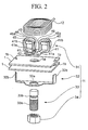
- the fastening member 11 is constituted, as shown for example in FIG. 2, by a clip member 31, a clip restriction member 32, a pin member 33, and a nut 34.
- one end portions of two clip pieces 41 are turnably connected to each other via a pin 42, and abutting surfaces 41A thereof are formed to be abuttable when the other end portions of the two clip pieces 41 turn toward each other.
- a notch portion 41 a that is approximately semicircular in plan view is formed on the abutting surface 41A of each clip piece 41, so that a pin member mounting hole 43 that is circular in plan view is formed by the notch portions 41 a when the abutting surfaces 41A of the two clip pieces 41 abut each other.
- the inner diameter of the pin member mounting hole 43 is formed to be a value that is slightly greater than an outer diameter of a reduced diameter portion 33b of the pin member 33 described below.
- a projection portion 41b that projects from the top of a surface 41B is formed on the other end portion of each clip piece 41.
- Each projection portion 41b of the two clip pieces 41 abuts the outer peripheral surface of the driving member 12 described below so as to sandwich the driving member 12 from both sides in the diameter direction.
- a bolt mounting hole 44 is formed in a distal end portion of each projection portion 41b, and a plate-shaped holding member 46 disposed at a position separated from the projection portion 44b by a predetermined distance is connected to a bolt 45 that is mounted in the bolt mounting hole 44.
- This holding member 46 abuts the inner peripheral surface of the driving member 12 described below, so that the driving member 12 is sandwiched from both sides in the diameter direction by the pair of holding members 46 and projection portions 41b.
- a bend portion 46a that extends toward the projection portion 41b so as to cover the end portion of the driving member 12 mounted between the holding member 46 and the projection portion 41b is formed in the holding member 46.
- An insertion hole 32a is formed in the center of the plate-shaped clip restriction member 32 for insertion of the pin member 33. Furthermore, the clip restriction member 32 is formed into an approximately U-shaped plate in which both end portions 32b bend so as to be perpendicular to the center portion. Both end portions 32b of the clip restriction member 32 abut the projection portions 41b when the other end portions of the two clip pieces 41 of the clip member 31 are separated from each other by a predetermined distance so as to restrict the turning of the two clip pieces 41.
- a thread portion 33a on which the nut 34 is mounted is formed on one end portion of the pin member 33, and a reduced diameter portion 33b having a diameter reduced by one step is formed at a position shifted from the other end toward the one end.
- the notch portion 41a of each clip piece 41 of the clip member 31 is mounted to the reduced diameter portion 33b.
- the deformed shape of the driving member 12 which constituted of a coil made from a shape memory alloy, is an oblong coil, while the memory shape thereof is a circular coil as shown for example in FIG 5.
- the driving member 12 assumes the deformed shape, and when the temperature of the driving member 12 is the predetermined temperature or higher, the driving member 12 reverts from the deformed shape to the memory shape.
- the abutting surfaces 41A of the two clip pieces 41 abut each other when the driving member 12 is in a deformed state, and when the driving member 12 reverts from the deformed shape to the memory shape, the other end portions of the two clip pieces 41 turn so as to separate from each other.
- each pin member insertion-hole 1a in which the pin member 33 is inserted and through-holes 1b in which both end portions 32b of the clip restriction member 32 are inserted are formed in the plate-shaped fastened members 1.
- each pin member insertion-hole 1a of the fastened members 1 is disposed to be coaxial with the insertion hole 32a of the clip restriction member 32, and the pin member insertion-holes 1a are formed to be continuous while facing the insertion hole 32a.
- the fastening device 10 has the aforementioned constitution. Next, the step of fixedly fastening the fastened member 1 with the fastening device 10 and the step of releasing the fastening will be explained.
- the both end portions 32b of the clip restriction member 32 are inserted in the through-holes 1b of the fastened members 1, and the pin member insertion-hole 1a of the fastened members 1 and the insertion hole 32a of the clip restriction member 32 are made continuous.
- the pin member 33 is inserted in each pin member insertion-hole 1a of the fastened members 1 and the insertion hole 32a of the clip restriction member 32, and the reduced diameter portion 33b of the other end portion of the pin member 34, as well as both end portions 32b of the clip restriction member 32, are made to protrude from the surface of the fastened members 1.
- the driving member 12 is mounted on the fastening member 11, and in the state of energization of the driving member 12 from the energizing device 13 being set to OFF, the notch portion 41 a of each clip piece 41 is mounted on the reduced diameter portion 33b of the pin member 33 so that the reduced diameter portion 33b of the pin member 33 is pinched from both sides by the notch portions 41a of the two clip pieces 41 of the driving member 12, while deforming the driving member 12 to a suitable shape by a suitable external force.
- the driving member 12 mounted on the fastening member 11 has an approximately circular shape, and when the driving member 12 is in its memory shape, the two clip pieces 41 of the fastening member 11 are set so that the other end portions thereof separate from each other.
- the driving member 12 deforms from the circular memory shape to the oblong deformation shape.
- the reduced diameter portion 33b of the pin member 33 is mounted in the pin member mounting hole 43 formed by the notch portions 41 a by the abutting of the abutting surfaces 41 A of the two clip pieces 41, and so relative displacement of the pin member 33 and the fastening member 11 is restricted along the axial direction of the pin member 33.
- the fastened members 1 are fixedly fastened by attaching the nut 34 to the thread portion 33a at the one end portion of the pin member 33 that protrudes from the surface of the clip restriction member 32.
- the switch 22 of the energizing device 13 When releasing the fastening of the fastened members 1, the switch 22 of the energizing device 13 is set to ON to start energization from the energizing device 13 to the driving member 12.
- the energization causes the temperature of the driving member 12 to rise.
- a restoring force occurs that causes the driving member 12 to revert from the deformed shape to the memory shape. Due to this restoring force, the other end portions of the two clip pieces 41 of the fastening member 11 turn so as to separate from each other.
- the notch portion 41 a of each clip piece 41 detaches from the reduced diameter portion 33b of the pin member 33, whereby the fastening of the fastened members 1 is released.
- the fastening device 10 is constituted by the fastening member 11 and the driving member 12, separable each other. This can prevent complication of the shapes of the members 11 and 12 compared to the case of integrally forming the fastening member 11 and the driving member 12 and can improve the versatility of the fastening device 10.
- the driving member 12, which is capable of releasing the fastening state of the fastening member 11 is formed of a shape memory alloy
- the fastening member 11 may be formed of a suitable construction material that can ensure the desired fastening strength so that the fastened members 1 can be fixedly fastened in a suitable manner.
- forming the driving member 12 in a coil with a simple shape can prevent an excessive increase in the electrical energy required when raising the temperature by resistance heating. Also, by altering the number of windings of the coil or the diameter of the coil, the magnitude of the restoring force when reverting from the deformed shape to the memory shape can be readily altered, and so the fastening strength and the driving force required for fastening release can be flexibly set in accordance with the place of application of the fastening device 10 and the fastened members 1.
- providing the clip restriction member 32 can prevent excessive turning of the two clip pieces 41 when the shape memory alloy of the driving member 12 that is mounted in the fastening member 11 reverts from the deformed shape to the memory shape.
- the driving member 12 was formed with a shaped memory alloy having a coil-shaped, but it is not limited thereto.
- it may be formed with a shape memory alloy having a suitable shape such as a U-shape.
- a spring 51 such as a belleville spring that applies a counterforce-along the axial direction of the pin member 33 may be provided between the clip restriction member 32 and the nut 34.
- a spring 51 such as a belleville spring that applies a counterforce-along the axial direction of the pin member 33 may be provided between the clip restriction member 32 and the nut 34.
- the fastening device 10 is constituted by the fastening member 11 that fixedly fastens fastened members 1, the driving member 12 that is capable of releasing the fastened state of the fastening member 11, and the energizing device 13, as shown for example in FIG. 10A, FIG. 10B, FIG. 11A and FIG 11B.
- the driving member 12 is formed by shape memory alloy wire (for example, 1 mm in diameter) having an insulating coating and wound into a coil.
- the energizing device 13 connected to both end portions of the driving member 12 is constituted by a power supply 21 and a switch 22 that controls the ON/OFF of energization from the power supply 21 to the driving member 12.
- the fastening member 11 is constituted by a pin holding member 61, a washer 62, a pin member 63, and a nut 64.
- a notch portion 61 a is formed in one end portion of the plate-shaped pin holding member 61, and a hook portion 61c that is bent into a hook-shaped is formed at the other end portion.
- the driving member 12 is mounted in this hook portion 61c.
- the inner wall face of the notch portion 61a is provided with a shape that follows a peripheral surface of the notch portion 63b of the pin member 63 described below, with the notch portion 63b of the pin member 63 being mounted thereon.
- a thread portion (not illustrated) on which the nut 64-is mounted is formed on one end portion of the pin member 64, and a concave portion 63 a having a shape that follows the outer periphery of the driving member 12 is formed on the other end portion.
- the notch portion 63b is formed at a position shifted from the concave portion 63a toward the one end portion.
- a deformed shape of the driving member 12 which is constituted by a coil made from a shape memory alloy, is an oblong coil, while a memory shape thereof, as shown for example in FIG. 11A, is a circular coil.
- a temperature of the driving member 12 is less then a predetermined temperature, the driving member 12 assumes the deformed shape, and when the temperature of the driving member 12 is the predetermined temperature or higher, the driving member 12 reverts from the deformed shape to the memory shape.
- the outer circumference side end portion of the driving member 12 that is mounted in the pin holding member 61, during a deformed state, is disposed at a position shifted more the other end portion side of the pin holding member 61 than a base of the notch portion 61a of the pin holding member 61.
- the driving member 12 reverts from the deformed state to a memory state, the outer circumference side end portion of the driving member 12 moves to a position shifted more to the one end portion side of the pin holding member 61 than the base of the notch portion 61a of the pin holding member 61.
- the notch portion 63b of the pin member 63 is mounted in the notch portion 61 a of the pin holding member 61. Thereby, relative displacement of the pin holding member 61 and the pin member 63 is restricted along an axial direction of the pin member 63.
- the outer circumference side end portion of the driving member 12 is pressed inward in a diameter direction by the concave portion 63a of the pin member 63.
- the driving member 12 is made to deform from the circular shape that is the memory shape to the oblong shape that is the deformed shape.
- the switch 22 of the energizing device 13 is set to ON to start energization from the energizing device 13 to the driving member 12.
- the energization causes the temperature of the driving member 12 to rise.
- a restoring force occurs that causes the driving member 12 to revert from the deformed shape to the memory shape. Due to this restoring force, the pin member 63 mounted in the notch portion 61a of the pin holding member 61 is pressed toward an outside of the notch portion 61 a. Then, as shown for example in FIG. 11A and 11B, the notch portion 63b of the pin member 33 detaches from the notch portion 61a of the pin holding member 61, whereby the fastening of the fastened members 1 is released.
- the present invention can be appropriately used for example when fastened members to be fastened which are required to be regularly fastened in a firm manner and quickly released during emergencies.
Landscapes
- Engineering & Computer Science (AREA)
- General Engineering & Computer Science (AREA)
- Mechanical Engineering (AREA)
- Snaps, Bayonet Connections, Set Pins, And Snap Rings (AREA)
- Connection Of Plates (AREA)
Abstract
Description
- The present invention relates to a fastening device.
- Priority is claimed on
Japanese Patent Application No. 2004-113231, filed April 7, 2004 - There is conventionally known a joint retaining member in which among a shaft, a header that fits on one end of the shaft and a nut that fits on the other end of the shaft, at least any one of the members is formed of a shape memory alloy, so that the joint retaining member can release the mechanical binding by shape change of the shape memory alloy in accordance with heating or cooling applied to this member (for example, refer to Patent Document 1).
- Also, there is conventionally known a fastening member that is formed of a shape memory alloy molded in such a shape that fastening can be released under heating, in which the fastening member is secondarily processed into a shape capable of fastening at temperatures at which it is not reverted to the memorized shape, and a microwave absorption material or infrared absorption material is coated on the surface of the fastening member or provided inside the fastening member (for example, refer to Patent Document 2).
- Patent Document 1:
Japanese Unexamined Patent Application, First Publication No. 2002-5124 - Patent Document 2:
Japanese Unexamined Patent Application, First Publication No. 2003-301815 - However, in the joint retaining member or the fastening member according to the aforementioned prior art, since the main body of the joint retaining member or the fastening member is formed of a shape memory alloy and has a relatively complicated shape, improving the efficiency of heat transfer during heating is difficult, and problems arise such as accumulation of the energy required until releasing the mechanical binding and fastening. Also, since the joint retention strength and fastening strength are restricted according to the material characteristics of the shape memory alloy, there is a risk that the desired strength cannot be ensured.
- The present invention was achieved in view of the aforementioned circumstances, and has as its object to provide a fastening device that can reduce the energy required for fastening release and readily release the fastening, and can ensure the desired fastening strength.
- In order to solve the aforementioned problems to attain the object, the fastening device according to the present invention is provided with a fastening member that fixedly fastens fastened members, and a driving member that is capable of releasing a fastening state of the fastening member by applying a driving force to a moving portion provided in the fastening member to drive it, wherein the driving member is formed of a shape memory alloy, and the driving force is a restoring force of the shape-memory alloy to its memory shape.
- According to the fastening device of this constitution, providing the fastening device with the fastening member and the driving member can prevent the shapes of the members from becoming complicated compared to the case of, for example, integrating the fastening member and the driving member, and can improve the versatility of the fastening device. Also, by forming the driving member, which is capable of releasing the fastening state of the fastening member, with a shape memory alloy, the fastening member may be formed of a suitable construction material that can ensure the desired fastening strength so that the fastened members can be fixedly fastened in a suitable manner.
- In the fastening device according to the present invention, presupposing the aforementioned invention, is provided with an energizing means that energizes the driving member, wherein the driving member is reverted to the memory shape by being energized by the energizing means.
- According to the fastening device of this constitution, the driving member, which is formed of a shape memory alloy, is restored from a deformed state to the memory shape when the temperature rises to the transformation point of the shape memory alloy or higher by resistance heat generation from energization from the energizing means, with the moving portion being driven by the restoring force at this time to release the fastening state of the fastening member.
- In the fastening device according to the present invention, presupposing the aforementioned invention, the fastening member is provided with a pin member that is attached to the fastened members, and a clip member that holds the pin member, the clip member includes two pinching members formed as the moving portion to be turnable about a turning axis, with the pin member being held so as to be pinched from both sides by the two pinching members, and the driving member releases the fastening state of the fastening member by turning the pinching members of the clip member about the turning axis.
- According to the fastening device of this constitution, the fastened members to which the pin member is attached are fixedly fastened by the clip member that pinches the pin member and a nut member that is attached to one end of the pin member. The driving member releases the pinched state of the pin member by turning the two pinching members constituting the clip member in opposite directions about the turning axis so as to mutually separate, and by separating the pin member from the clip member releases the fastening state of the fastening member.
- In the fastening device according to the present invention, presupposing the aforementioned invention, the fastening member is provided with a pin member that is attached to the fastened members, and a clip member that holds the pin member, the clip member includes a notch portion in which the pin member, which is the moving portion, is attached, the pin member is held by an inside wall surface of the notch portion so as to be sandwiched from both sides, the driving member presses the pin member toward an outside of the notch portion of the clip member, and the fastening state of the fastening member is released by separating the pin member from the notch portion.
- According to the fastening device of this constitution, the fastened members to which the pin member is attached are fixedly fastened by the clip member that pinches the pin member and a nut member that is attached to one end of the pin member. The driving member separates the pin member from the notch portion by pressing the pin member, which is attached to the notch portion of the clip member, to the outside, thereby releasing the fastening state of the fastening member.
- In the fastening device according to the present invention, presupposing the aforementioned invention, the clip member includes a holding member that holds the driving member.
- According to the fastening device of this constitution, the driving member is held at the clip member, whereby due to the restoring force when the shape memory alloy of the driving member reverts from the deformed shape to the memory shape, the two pinching members constituting the clip member are turned about the turning axis, and by pressing toward the outside the pin member, which is attached to the notch portion of the clip member, can release the fastening state of the fastening member.
- In the fastening device according to the present invention, presupposing the aforementioned invention, the clip member includes a restriction member that restricts driving of the moving portion.
- According to the fastening device of this constitution, when the shape memory alloy of the driving member held in the clip member reverts from the deformed shape to the memory shape, excessive turning of the two pinching members constituting the clip member, and excessive deformation of the moving member in the direction that presses the pin member, which is attached to the notch portion of the clip member, outward can be prevented.
- In the fastening device according to the present invention, presupposing the aforementioned invention, the pin member includes either one of a mutually fitting concave portion and convex portion, and the clip member includes the other one of the concave portion and convex portion.
- According to the fastening device of this constitution, when the pin member is held in the clip member, the pin member and the clip member are firmly fixed, and the desired fastening strength can be ensured by the fitting of either one of the concave portion and convex portion provided in the pin member and either one of the concave portion and convex portion provided in the clip member.
- In the fastening device according-to the present invention, presupposing the aforementioned invention, the driving member is formed-of a shape memory alloy in a coil shape or a U-shape, and being deformed in the fastening state of the fastening member so that a distance between two predetermined positions of the shape memory alloy becomes closer than a distance in the memory shape.
- According to the fastening device of this constitution, when the shape memory alloy of the driving member reverts from the deformed shape to the memory shape, the distance between the two predetermined positions of the shape memory alloy increases, whereby the driving force acts on the moving portion provided in the fastening member so that the fastening state of the fastening member is easily released. Moreover, since the driving member has a small cross-sectional area and is formed with a simple shape, resistance heating by directly energizing the driving member is possible, and so the fastening can be readily released while reducing the electrical energy required to raise the temperature of the driving member to the transformation point of the shape memory alloy or higher compared to the case of indirect heating using a heater or the like.
- According to the fastening device of the present invention, providing the fastening device with the fastening member and the driving member can prevent the shapes of the members from becoming complicated compared to the case of, for example, integrating the fastening member and the driving member, and can improve the versatility of the fastening device. In addition, by forming the driving member, which is capable of releasing the fastening state of the fastening member, with a shape memory alloy, the fastening member may be formed of a suitable construction material that can ensure the desired fastening strength so that the fastened members can be fixedly fastened in a suitable manner.
- Furthermore, according to the fastening device of the present invention, when the shape memory alloy of the driving member held in the clip member reverts from the deformed shape to the memory shape, excessive turning of the two pinching members constituting the clip member, and excessive deformation of the moving member in the direction that presses the pin member, which is attached to the notch portion of the clip member, outward can be prevented.
- Furthermore, according to the fastening device of the present invention, the pin member and the clip member are firmly fixed, and the desired fastening strength can be ensured.
- Furthermore, according to the fastening device of the present invention, the fastening state of the fastening member is easily released by the restoring force when the shape memory alloy of the driving member reverts from the deformed shape to the memory shape. In addition, since the driving member has a small cross-sectional area and is formed with a simple shape, resistance heating by directly energizing the driving member is possible, and so the fastening can be readily released while reducing the electrical energy required to raise the temperature of the driving member to the transformation point of the shape memory alloy or higher compared to the case of indirect heating using a heater or the like.
-
- FIG. 1 is a perspective view of the fastening device according to the first embodiment of the present invention.
- FIG. 2 is an exploded perspective view of the fastening device shown in FIG 1.
- FIG. 3 is a plan view of the clip member shown in FIG. 1.
- FIG. 4 is a plan view of the driving member attached to the clip member shown in FIG. 1.
- FIG. 5 is a plan view of the driving member attached to the clip member shown in FIG 1.
- FIG 6 is a sectional side view of the fastening device shown in FIG. 1.
- FIG. 7 is a sectional side view of the fastening device shown in FIG. 1.
- FIG. 8 is a sectional side view of the fastening device according to a modification example of the present embodiment.
- FIG 9 is a sectional side view of the fastening device according to a modification example of the present embodiment.
- FIG. 10A is a plan view of the fastening device according to the second embodiment of the present invention.
- FIG. 10B is a sectional view along the line C-C shown in FIG. 10A.
- FIG. 11A is a plan view of the fastening device according to the second embodiment of the present invention.
- FIG. 11B is a sectional view along the line C-C shown in FIG 11A.
-
- 1:
- fastened member
- 10:
- fastening device
- 11:
- fastening member
- 12:
- driving member
- 13:
- energizing device
- 31:
- clip member
- 32:
- clip restriction member
- 33:
- pin member
- 33b:
- reduced diameter portion
- 41:
- clip pieces
- 41b:
- projection portion
- 46:
- holding members
- 61:
- pin holding member
- 61a:
- notch
- 61c:
- hook portion
- 63b:
- notch portion
- The first embodiment of the present invention is explained below, referring to the accompanying drawings.
- A
fastening device 10 according to the present embodiment is constituted, as shown for example in FIG 1, by afastening member 11 that fixedly fastens fastenedmembers 1, a drivingmember 12 that is capable of releasing a fastened state of thefastening member 11, and an-energizingdevice 13. For example, the drivingmember 12 is formed by shape memory alloy wire (for example, 1 mm in diameter) having an insulating coating and wound into a coil. The energizingdevice 13 connected to both end portions of the drivingmember 12 is constituted by apower supply 21 and aswitch 22 that controls an ON/OFF of energization from thepower supply 21 to the drivingmember 12. - The
fastening member 11 is constituted, as shown for example in FIG. 2, by aclip member 31, aclip restriction member 32, apin member 33, and anut 34. - As for the
clip member 31, as shown for example in FIG. 2 and FIG. 3, one end portions of twoclip pieces 41 are turnably connected to each other via apin 42, and abuttingsurfaces 41A thereof are formed to be abuttable when the other end portions of the twoclip pieces 41 turn toward each other. - A
notch portion 41 a that is approximately semicircular in plan view is formed on theabutting surface 41A of eachclip piece 41, so that a pinmember mounting hole 43 that is circular in plan view is formed by thenotch portions 41 a when the abuttingsurfaces 41A of the twoclip pieces 41 abut each other. The inner diameter of the pinmember mounting hole 43 is formed to be a value that is slightly greater than an outer diameter of a reduceddiameter portion 33b of thepin member 33 described below. - Also, a
projection portion 41b that projects from the top of asurface 41B is formed on the other end portion of eachclip piece 41. Eachprojection portion 41b of the twoclip pieces 41 abuts the outer peripheral surface of the drivingmember 12 described below so as to sandwich the drivingmember 12 from both sides in the diameter direction. Furthermore, abolt mounting hole 44 is formed in a distal end portion of eachprojection portion 41b, and a plate-shaped holdingmember 46 disposed at a position separated from the projection portion 44b by a predetermined distance is connected to abolt 45 that is mounted in thebolt mounting hole 44. This holdingmember 46 abuts the inner peripheral surface of the drivingmember 12 described below, so that the drivingmember 12 is sandwiched from both sides in the diameter direction by the pair of holdingmembers 46 andprojection portions 41b. - A
bend portion 46a that extends toward theprojection portion 41b so as to cover the end portion of the drivingmember 12 mounted between the holdingmember 46 and theprojection portion 41b is formed in the holdingmember 46. - An
insertion hole 32a is formed in the center of the plate-shapedclip restriction member 32 for insertion of thepin member 33. Furthermore, theclip restriction member 32 is formed into an approximately U-shaped plate in which both endportions 32b bend so as to be perpendicular to the center portion. Bothend portions 32b of theclip restriction member 32 abut theprojection portions 41b when the other end portions of the twoclip pieces 41 of theclip member 31 are separated from each other by a predetermined distance so as to restrict the turning of the twoclip pieces 41. - As shown for example in FIG. 2, a
thread portion 33a on which thenut 34 is mounted is formed on one end portion of thepin member 33, and a reduceddiameter portion 33b having a diameter reduced by one step is formed at a position shifted from the other end toward the one end. Thenotch portion 41a of eachclip piece 41 of theclip member 31 is mounted to the reduceddiameter portion 33b. - As shown for example in FIG. 4, the deformed shape of the driving
member 12, which constituted of a coil made from a shape memory alloy, is an oblong coil, while the memory shape thereof is a circular coil as shown for example in FIG 5. When a temperature of the drivingmember 12 is less then a predetermined temperature, the drivingmember 12 assumes the deformed shape, and when the temperature of the drivingmember 12 is the predetermined temperature or higher, the drivingmember 12 reverts from the deformed shape to the memory shape. - In the
clip member 31 on which the drivingmember 12 is mounted, as described below, the abuttingsurfaces 41A of the twoclip pieces 41 abut each other when the drivingmember 12 is in a deformed state, and when the drivingmember 12 reverts from the deformed shape to the memory shape, the other end portions of the twoclip pieces 41 turn so as to separate from each other. - As shown for example in FIG. 2, each pin member insertion-
hole 1a in which thepin member 33 is inserted and through-holes 1b in which both endportions 32b of theclip restriction member 32 are inserted are formed in the plate-shaped fastenedmembers 1. In a state of bothend portions 32b of theclip restriction member 32 being inserted in the through-holes 1b of the fastenedmembers 1, each pin member insertion-hole 1a of the fastenedmembers 1 is disposed to be coaxial with theinsertion hole 32a of theclip restriction member 32, and the pin member insertion-holes 1a are formed to be continuous while facing theinsertion hole 32a. - The
fastening device 10 according to the present embodiment has the aforementioned constitution. Next, the step of fixedly fastening the fastenedmember 1 with thefastening device 10 and the step of releasing the fastening will be explained. - When fixedly fastening the fastened
members 1, at first, the bothend portions 32b of theclip restriction member 32 are inserted in the through-holes 1b of the fastenedmembers 1, and the pin member insertion-hole 1a of the fastenedmembers 1 and theinsertion hole 32a of theclip restriction member 32 are made continuous. - Then, the
pin member 33 is inserted in each pin member insertion-hole 1a of the fastenedmembers 1 and theinsertion hole 32a of theclip restriction member 32, and the reduceddiameter portion 33b of the other end portion of thepin member 34, as well as both endportions 32b of theclip restriction member 32, are made to protrude from the surface of the fastenedmembers 1. - Next, the driving
member 12 is mounted on thefastening member 11, and in the state of energization of the drivingmember 12 from the energizingdevice 13 being set to OFF, thenotch portion 41 a of eachclip piece 41 is mounted on the reduceddiameter portion 33b of thepin member 33 so that the reduceddiameter portion 33b of thepin member 33 is pinched from both sides by thenotch portions 41a of the twoclip pieces 41 of the drivingmember 12, while deforming the drivingmember 12 to a suitable shape by a suitable external force. - Here, the driving
member 12 mounted on thefastening member 11 has an approximately circular shape, and when the drivingmember 12 is in its memory shape, the twoclip pieces 41 of thefastening member 11 are set so that the other end portions thereof separate from each other. By deforming the drivingmember 12 so that the other end portions of the twoclip pieces 41 approach each other, the drivingmember 12 deforms from the circular memory shape to the oblong deformation shape. The reduceddiameter portion 33b of thepin member 33 is mounted in the pinmember mounting hole 43 formed by thenotch portions 41 a by the abutting of the abuttingsurfaces 41 A of the twoclip pieces 41, and so relative displacement of thepin member 33 and thefastening member 11 is restricted along the axial direction of thepin member 33. - As shown for example in FIG. 6, the fastened
members 1 are fixedly fastened by attaching thenut 34 to thethread portion 33a at the one end portion of thepin member 33 that protrudes from the surface of theclip restriction member 32. - When releasing the fastening of the fastened
members 1, theswitch 22 of the energizingdevice 13 is set to ON to start energization from the energizingdevice 13 to the drivingmember 12. The energization causes the temperature of the drivingmember 12 to rise. When the temperature reaches a temperature equal to or greater than the transformation point of the shape memory alloy, a restoring force occurs that causes the drivingmember 12 to revert from the deformed shape to the memory shape. Due to this restoring force, the other end portions of the twoclip pieces 41 of thefastening member 11 turn so as to separate from each other. As shown for example in FIG. 7, thenotch portion 41 a of eachclip piece 41 detaches from the reduceddiameter portion 33b of thepin member 33, whereby the fastening of the fastenedmembers 1 is released. - At this time, when the other end portions of the two
clip pieces 41 separate from each other by a predetermined distance, as shown for example in FIG. 5, theprojection portion 41b of eachclip piece 41 abuts bothend portions 32b of theclip restriction member 32, and so excessive turning of the twoclip pieces 41 is restricted. - As stated above, according to the
fastening device 10 of the present embodiment, thefastening device 10 is constituted by thefastening member 11 and the drivingmember 12, separable each other. This can prevent complication of the shapes of themembers fastening member 11 and the drivingmember 12 and can improve the versatility of thefastening device 10. In addition, since the drivingmember 12, which is capable of releasing the fastening state of thefastening member 11, is formed of a shape memory alloy, thefastening member 11 may be formed of a suitable construction material that can ensure the desired fastening strength so that the fastenedmembers 1 can be fixedly fastened in a suitable manner. - Furthermore, forming the driving
member 12 in a coil with a simple shape can prevent an excessive increase in the electrical energy required when raising the temperature by resistance heating. Also, by altering the number of windings of the coil or the diameter of the coil, the magnitude of the restoring force when reverting from the deformed shape to the memory shape can be readily altered, and so the fastening strength and the driving force required for fastening release can be flexibly set in accordance with the place of application of thefastening device 10 and the fastenedmembers 1. - Furthermore, providing the
clip restriction member 32 can prevent excessive turning of the twoclip pieces 41 when the shape memory alloy of the drivingmember 12 that is mounted in thefastening member 11 reverts from the deformed shape to the memory shape. - In the above-described embodiment, the driving
member 12 was formed with a shaped memory alloy having a coil-shaped, but it is not limited thereto. For example, it may be formed with a shape memory alloy having a suitable shape such as a U-shape. - In addition, as shown for-example in FIG. 8 and FIG. 9, a
spring 51 such as a belleville spring that applies a counterforce-along the axial direction of thepin member 33 may be provided between theclip restriction member 32 and thenut 34. In this case, when thenotch portion 41a of eachclip piece 41 detaches from the reduceddiameter portion 33b of thepin member 33, thepin member 33 can be readily pulled out from the fastenedmembers 1. - The second embodiment of the present invention is explained below, referring to the accompanying drawings.
- The
fastening device 10 according to this embodiment is constituted by thefastening member 11 that fixedly fastens fastenedmembers 1, the drivingmember 12 that is capable of releasing the fastened state of thefastening member 11, and the energizingdevice 13, as shown for example in FIG. 10A, FIG. 10B, FIG. 11A and FIG 11B. For example, the drivingmember 12 is formed by shape memory alloy wire (for example, 1 mm in diameter) having an insulating coating and wound into a coil. The energizingdevice 13 connected to both end portions of the drivingmember 12 is constituted by apower supply 21 and aswitch 22 that controls the ON/OFF of energization from thepower supply 21 to the drivingmember 12. - The
fastening member 11 is constituted by apin holding member 61, awasher 62, apin member 63, and anut 64. - A
notch portion 61 a is formed in one end portion of the plate-shapedpin holding member 61, and ahook portion 61c that is bent into a hook-shaped is formed at the other end portion. The drivingmember 12 is mounted in thishook portion 61c. The inner wall face of thenotch portion 61a is provided with a shape that follows a peripheral surface of thenotch portion 63b of thepin member 63 described below, with thenotch portion 63b of thepin member 63 being mounted thereon. - A thread portion (not illustrated) on which the nut 64-is mounted is formed on one end portion of the
pin member 64, and aconcave portion 63 a having a shape that follows the outer periphery of the drivingmember 12 is formed on the other end portion. In addition, thenotch portion 63b is formed at a position shifted from theconcave portion 63a toward the one end portion. - As shown for example in FIG. 10A, a deformed shape of the driving
member 12, which is constituted by a coil made from a shape memory alloy, is an oblong coil, while a memory shape thereof, as shown for example in FIG. 11A, is a circular coil. When a temperature of the drivingmember 12 is less then a predetermined temperature, the drivingmember 12 assumes the deformed shape, and when the temperature of the drivingmember 12 is the predetermined temperature or higher, the drivingmember 12 reverts from the deformed shape to the memory shape. - The outer circumference side end portion of the driving
member 12 that is mounted in thepin holding member 61, during a deformed state, is disposed at a position shifted more the other end portion side of thepin holding member 61 than a base of thenotch portion 61a of thepin holding member 61. When the drivingmember 12 reverts from the deformed state to a memory state, the outer circumference side end portion of the drivingmember 12 moves to a position shifted more to the one end portion side of thepin holding member 61 than the base of thenotch portion 61a of thepin holding member 61. - When fixedly fastening the fastened
members 1 by thefastening device 10 according to the second embodiment, first thenotch portion 63b of thepin member 63 is mounted in thenotch portion 61 a of thepin holding member 61. Thereby, relative displacement of thepin holding member 61 and thepin member 63 is restricted along an axial direction of thepin member 63. - At this time, in a state of energization of the driving
member 12 from the energizingdevice 13 being set to OFF, the outer circumference side end portion of the drivingmember 12 is pressed inward in a diameter direction by theconcave portion 63a of thepin member 63. Thereby, the drivingmember 12 is made to deform from the circular shape that is the memory shape to the oblong shape that is the deformed shape. - As shown for example in FIG 10B, by mounting a
washer 62 and thenut 64 on thepin member 63 that projects from the surface of the fastenedmembers 1, the fastenedmembers 1 are fixedly fastened. - On the other hand, when releasing the fastening of the fastened
member 1, theswitch 22 of the energizingdevice 13 is set to ON to start energization from the energizingdevice 13 to the drivingmember 12. The energization causes the temperature of the drivingmember 12 to rise. When the temperature reaches a temperature equal to or greater than the transformation point of the shape memory alloy, a restoring force occurs that causes the drivingmember 12 to revert from the deformed shape to the memory shape. Due to this restoring force, thepin member 63 mounted in thenotch portion 61a of thepin holding member 61 is pressed toward an outside of thenotch portion 61 a. Then, as shown for example in FIG. 11A and 11B, thenotch portion 63b of thepin member 33 detaches from thenotch portion 61a of thepin holding member 61, whereby the fastening of the fastenedmembers 1 is released. - While preferred embodiments of the invention have been described and illustrated above, it should be understood that the present invention is not limited to these embodiments and can be widely applied. Additions, omissions, substitutions, and other modifications can be made without departing from the spirit or scope of the present invention. Accordingly, the invention is not to be considered as being limited by the foregoing description, and is only limited by the scope of the appended claims.
- The present invention can be appropriately used for example when fastened members to be fastened which are required to be regularly fastened in a firm manner and quickly released during emergencies.
Claims (8)
- A fastening device comprising:a fastening member that fixedly fastens fastened members; anda driving member that is capable of releasing a fastening state of the fastening member by applying a driving force to a moving portion provided in the fastening member to drive it, whereinthe driving member is formed of a shape memory alloy, and the driving force is a restoring force of the shape memory alloy to its memory shape.
- The fastening device according to claim 1, further comprising
an energizing means that energizes the driving member, wherein
the driving member is reverted to the memory shape by being energized by the energizing means. - The fastening device according to claim 1, wherein
the fastening member includes a pin member that is attached to the fastened members, and a clip member that holds the pin member,
the clip member includes two pinching members formed as the moving portion to be turnable about a turning axis, with the pin member being held so as to be pinched from both sides by the two pinching members, and
the driving member releases the fastening state of the fastening member by turning the pinching members of the clip member about the turning axis. - The fastening device according to claim 1, wherein
the fastening member includes a pin member that is attached to the fastened members, and a clip member that holds the pin member,
the clip member includes a notch portion in which the pin member, which is the moving portion, is attached,
the pin member is held by an inside wall surface of the notch portion so as to be sandwiched from both sides,
the driving member presses the pin member toward an outside of the notch portion of the clip member, and the fastening state of the fastening member is released by separating the pin member from the notch portion. - The fastening device according to claim 3, wherein
the clip member includes a holding member that holds the driving member. - The fastening device according to claim 5, wherein
the clip member includes a restriction member that restricts driving of the moving portion. - The fastening device according to claim 3, wherein
the pin member includes either one of a mutually fitting concave portion and convex portion, and
the clip member includes the other one of the concave portion and convex portion. - The fastening device according to claim 1, wherein
the driving member is formed of a shape memory alloy in a coil shape or a U-shape, and being deformed in the fastening state of the fastening member so that a distance between-two predetermined positions of the shape memory alloy becomes closer than a distance in the memory shape.
Applications Claiming Priority (2)
| Application Number | Priority Date | Filing Date | Title |
|---|---|---|---|
| JP2004113231A JP4339167B2 (en) | 2004-04-07 | 2004-04-07 | Fastening device |
| PCT/JP2005/006656 WO2005098245A1 (en) | 2004-04-07 | 2005-04-05 | Fastening device |
Publications (3)
| Publication Number | Publication Date |
|---|---|
| EP1734266A1 true EP1734266A1 (en) | 2006-12-20 |
| EP1734266A4 EP1734266A4 (en) | 2009-02-18 |
| EP1734266B1 EP1734266B1 (en) | 2010-05-12 |
Family
ID=35125147
Family Applications (1)
| Application Number | Title | Priority Date | Filing Date |
|---|---|---|---|
| EP05728787A Expired - Lifetime EP1734266B1 (en) | 2004-04-07 | 2005-04-05 | Fastening device |
Country Status (5)
| Country | Link |
|---|---|
| US (1) | US7753632B2 (en) |
| EP (1) | EP1734266B1 (en) |
| JP (1) | JP4339167B2 (en) |
| DE (1) | DE602005021211D1 (en) |
| WO (1) | WO2005098245A1 (en) |
Families Citing this family (14)
| Publication number | Priority date | Publication date | Assignee | Title |
|---|---|---|---|---|
| JP4480091B2 (en) * | 2006-08-31 | 2010-06-16 | 株式会社ユニオン精密 | Fastening structure and stationery |
| US8221043B2 (en) * | 2008-02-18 | 2012-07-17 | Lockheed Martin Corporation | Releasable fastener systems and methods |
| US8568053B2 (en) * | 2008-04-14 | 2013-10-29 | Space Systems/Loral, Llc | Radial release device |
| US9290261B2 (en) * | 2011-06-09 | 2016-03-22 | United Technologies Corporation | Method and assembly for attaching components |
| US10059431B2 (en) | 2011-06-09 | 2018-08-28 | United Technologies Corporation | Method and apparatus for attaching components having dissimilar rates of thermal expansion |
| US20130042461A1 (en) * | 2011-08-17 | 2013-02-21 | Composite Technology Development, Inc. | Shape memory polymer devices |
| GB201201343D0 (en) * | 2012-01-27 | 2012-03-14 | Rolls Royce Plc | Threaded fastener assembly and method of locking a threaded fastener |
| US9742058B1 (en) * | 2015-08-06 | 2017-08-22 | Gregory A. O'Neill, Jr. | Deployable quadrifilar helical antenna |
| FR3061353B1 (en) * | 2016-12-22 | 2019-05-10 | Saft | SELF-ACTIVATION DEVICE FOR ELECTROMECHANICAL SWITCH |
| CN106627083B (en) * | 2017-01-13 | 2023-09-05 | 上海蔚来汽车有限公司 | Quick locking and unlocking kit |
| JP7380398B2 (en) * | 2020-04-10 | 2023-11-15 | オムロン株式会社 | mounting attachment |
| CN111520381B (en) * | 2020-04-30 | 2022-01-18 | 广东电网有限责任公司东莞供电局 | Bolt assembly and primary equipment |
| DE102020130625A1 (en) | 2020-11-19 | 2022-05-19 | Vega Grieshaber Kg | Clamping device with shape memory alloy, sensor with such a clamping device and method for clamping a component |
| DE102021105944B4 (en) | 2021-03-11 | 2023-05-17 | Festo Se & Co. Kg | coupling device |
Family Cites Families (23)
| Publication number | Priority date | Publication date | Assignee | Title |
|---|---|---|---|---|
| US1926925A (en) * | 1931-04-07 | 1933-09-12 | Gulf Res & Dev Corp | Pin, bolt, and other connecting device |
| US3408890A (en) * | 1967-01-27 | 1968-11-05 | Hi Shear Corp | Separable fastener assembly |
| US3454286A (en) * | 1967-03-01 | 1969-07-08 | Us Navy | Thermally operated release mechanism |
| US3546996A (en) * | 1969-04-10 | 1970-12-15 | Atomic Energy Commission | Release latch actuated by temperature excursion |
| US3613732A (en) * | 1969-07-17 | 1971-10-19 | Robertshaw Controls Co | Temperature-responsive valve operators |
| US3725835A (en) * | 1970-07-20 | 1973-04-03 | J Hopkins | Memory material actuator devices |
| US4096993A (en) * | 1977-01-21 | 1978-06-27 | Emerson Electric Co. | Compensated control valve |
| JPS55179216U (en) | 1979-06-12 | 1980-12-23 | ||
| US4505532A (en) | 1982-07-23 | 1985-03-19 | Raychem Corporation | Array package connector |
| US5119555A (en) * | 1988-09-19 | 1992-06-09 | Tini Alloy Company | Non-explosive separation device |
| JPH063411B2 (en) * | 1989-11-28 | 1994-01-12 | 東機産業株式会社 | Rotor viscometer rotor automatic attachment / detachment device |
| US5144813A (en) * | 1990-04-06 | 1992-09-08 | Robertshaw Controls Company | Control device having a shape memory wire, refrigerator system utilizing the control device and methods of making the same |
| US5129753A (en) * | 1990-11-13 | 1992-07-14 | Trw Inc. | Shape memory wire latch mechanism |
| JP2536786Y2 (en) | 1991-07-03 | 1997-05-28 | 関東自動車工業株式会社 | Press-type side pin retaining device |
| JP3167448B2 (en) | 1992-09-17 | 2001-05-21 | 三菱樹脂株式会社 | Reversible thermosensitive recording material |
| US5722709A (en) * | 1996-10-30 | 1998-03-03 | Hughes Electronics | Separation device using a shape memory alloy retainer |
| DE19843965C2 (en) * | 1998-09-24 | 2000-07-13 | Daimler Chrysler Ag | Hold and release mechanism with a shape memory actuator |
| JP2000127927A (en) | 1998-10-20 | 2000-05-09 | Toyota Motor Corp | Automatic stopping/starting device of engine |
| JP2001268956A (en) * | 2000-03-17 | 2001-09-28 | Sony Corp | Driving device and driving method |
| JP2001263221A (en) | 2000-03-22 | 2001-09-26 | Minolta Co Ltd | Control device using actuator including shape memory alloy |
| JP2002005124A (en) | 2000-06-19 | 2002-01-09 | Tokin Corp | Coupling holding parts |
| JP2003285862A (en) * | 2002-03-28 | 2003-10-07 | Nec Tokin Corp | Binding band |
| JP2003301815A (en) | 2002-04-08 | 2003-10-24 | Sharp Corp | Fastening member |
-
2004
- 2004-04-07 JP JP2004113231A patent/JP4339167B2/en not_active Expired - Fee Related
-
2005
- 2005-04-05 US US11/547,563 patent/US7753632B2/en not_active Expired - Fee Related
- 2005-04-05 WO PCT/JP2005/006656 patent/WO2005098245A1/en not_active Ceased
- 2005-04-05 DE DE602005021211T patent/DE602005021211D1/en not_active Expired - Lifetime
- 2005-04-05 EP EP05728787A patent/EP1734266B1/en not_active Expired - Lifetime
Also Published As
| Publication number | Publication date |
|---|---|
| US7753632B2 (en) | 2010-07-13 |
| EP1734266A4 (en) | 2009-02-18 |
| JP2005299728A (en) | 2005-10-27 |
| US20070212189A1 (en) | 2007-09-13 |
| DE602005021211D1 (en) | 2010-06-24 |
| JP4339167B2 (en) | 2009-10-07 |
| EP1734266B1 (en) | 2010-05-12 |
| WO2005098245A1 (en) | 2005-10-20 |
Similar Documents
| Publication | Publication Date | Title |
|---|---|---|
| EP1734266A1 (en) | Fastening device | |
| US6239686B1 (en) | Temperature responsive switch with shape memory actuator | |
| US6752668B2 (en) | Electrical connector | |
| EP2923083B1 (en) | Shape memory alloy actuating element with improved fatigue resistance | |
| CN102362545B (en) | Connecting element for a helical heating wire of a tubular heating body and method for its manufacture | |
| US7868731B2 (en) | Thermal overload relay | |
| KR20000035594A (en) | Thermal switch | |
| US11749479B2 (en) | Temperature-dependent switch | |
| JPS62150674A (en) | Shape-memory actuator for multi-contact connector | |
| TW200938737A (en) | Lock ring | |
| EP1440857A1 (en) | A device for engaging the push-rod of the power brake to the brake pedal of a motor vehicle | |
| JP2014501362A (en) | Pitch cable having a flexible core around which a coil is wound | |
| JP3490675B2 (en) | Battery terminal | |
| EP3032653B1 (en) | Aluminum electric wire connection structure | |
| EP3757418B1 (en) | Disc brake for vehicles, in particular for commercial vehicles | |
| US20090071146A1 (en) | Self assembling/quick assembly structure using shape memory alloy materials | |
| US7522030B2 (en) | Starter relay | |
| JPH0612593Y2 (en) | Thermostat switch cap and bracket structure | |
| JP3583004B2 (en) | Breaker device | |
| JP2010255770A (en) | Chain clamping device | |
| JP3493798B2 (en) | Combination device for plate-shaped parts and compression coil springs | |
| CN212394581U (en) | Cooking utensil | |
| US10859067B2 (en) | Variable stiffness actuator | |
| CN215567569U (en) | Spring unit | |
| EP1119081B1 (en) | Lamp-holder with quick-locking device for the electric cable |
Legal Events
| Date | Code | Title | Description |
|---|---|---|---|
| PUAI | Public reference made under article 153(3) epc to a published international application that has entered the european phase |
Free format text: ORIGINAL CODE: 0009012 |
|
| 17P | Request for examination filed |
Effective date: 20061004 |
|
| AK | Designated contracting states |
Kind code of ref document: A1 Designated state(s): DE FR GB |
|
| DAX | Request for extension of the european patent (deleted) | ||
| RBV | Designated contracting states (corrected) |
Designated state(s): DE FR GB |
|
| A4 | Supplementary search report drawn up and despatched |
Effective date: 20090119 |
|
| GRAP | Despatch of communication of intention to grant a patent |
Free format text: ORIGINAL CODE: EPIDOSNIGR1 |
|
| 17Q | First examination report despatched |
Effective date: 20090612 |
|
| GRAS | Grant fee paid |
Free format text: ORIGINAL CODE: EPIDOSNIGR3 |
|
| RIN1 | Information on inventor provided before grant (corrected) |
Inventor name: TAGUCHI, KATSUAKI,C/O K.K. HONDA GIJUTSU KENKYUSHO Inventor name: SUZUKI, SHUNJI,C/O K.K. HONDA GIJUTSU KENKYUSHO Inventor name: URUSHIYAMA, YUTA,C/O K.K. HONDA GIJUTSU KENKYUSHO Inventor name: NAITOU, TADASHI,C/O K.K. HONDA GIJUTSU KENKYUSHO |
|
| GRAA | (expected) grant |
Free format text: ORIGINAL CODE: 0009210 |
|
| RIN1 | Information on inventor provided before grant (corrected) |
Inventor name: TAGUCHI, KATSUAKI,C/O K.K. HONDA GIJUTSU KENKYUSHO Inventor name: SUZUKI, SHUNJI,C/O K.K. HONDA GIJUTSU KENKYUSHO Inventor name: URUSHIYAMA, YUTA,C/O K.K. HONDA GIJUTSU KENKYUSHO Inventor name: NAITOU, TADASHI,C/O K.K. HONDA GIJUTSU KENKYUSHO |
|
| AK | Designated contracting states |
Kind code of ref document: B1 Designated state(s): DE FR GB |
|
| REG | Reference to a national code |
Ref country code: GB Ref legal event code: FG4D |
|
| REF | Corresponds to: |
Ref document number: 602005021211 Country of ref document: DE Date of ref document: 20100624 Kind code of ref document: P |
|
| PLBE | No opposition filed within time limit |
Free format text: ORIGINAL CODE: 0009261 |
|
| STAA | Information on the status of an ep patent application or granted ep patent |
Free format text: STATUS: NO OPPOSITION FILED WITHIN TIME LIMIT |
|
| 26N | No opposition filed |
Effective date: 20110215 |
|
| REG | Reference to a national code |
Ref country code: DE Ref legal event code: R097 Ref document number: 602005021211 Country of ref document: DE Effective date: 20110214 |
|
| PGFP | Annual fee paid to national office [announced via postgrant information from national office to epo] |
Ref country code: DE Payment date: 20110215 Year of fee payment: 7 |
|
| GBPC | Gb: european patent ceased through non-payment of renewal fee |
Effective date: 20110405 |
|
| REG | Reference to a national code |
Ref country code: FR Ref legal event code: ST Effective date: 20111230 |
|
| PG25 | Lapsed in a contracting state [announced via postgrant information from national office to epo] |
Ref country code: FR Free format text: LAPSE BECAUSE OF NON-PAYMENT OF DUE FEES Effective date: 20110502 |
|
| PG25 | Lapsed in a contracting state [announced via postgrant information from national office to epo] |
Ref country code: GB Free format text: LAPSE BECAUSE OF NON-PAYMENT OF DUE FEES Effective date: 20110405 |
|
| REG | Reference to a national code |
Ref country code: DE Ref legal event code: R119 Ref document number: 602005021211 Country of ref document: DE Effective date: 20121101 |
|
| PG25 | Lapsed in a contracting state [announced via postgrant information from national office to epo] |
Ref country code: DE Free format text: LAPSE BECAUSE OF NON-PAYMENT OF DUE FEES Effective date: 20121101 |