EP1733921A1 - Cargo securing device - Google Patents
Cargo securing device Download PDFInfo
- Publication number
- EP1733921A1 EP1733921A1 EP05105403A EP05105403A EP1733921A1 EP 1733921 A1 EP1733921 A1 EP 1733921A1 EP 05105403 A EP05105403 A EP 05105403A EP 05105403 A EP05105403 A EP 05105403A EP 1733921 A1 EP1733921 A1 EP 1733921A1
- Authority
- EP
- European Patent Office
- Prior art keywords
- securing device
- cargo securing
- guiding rail
- arm member
- clamping
- Prior art date
- Legal status (The legal status is an assumption and is not a legal conclusion. Google has not performed a legal analysis and makes no representation as to the accuracy of the status listed.)
- Granted
Links
Images



Classifications
-
- B—PERFORMING OPERATIONS; TRANSPORTING
- B60—VEHICLES IN GENERAL
- B60P—VEHICLES ADAPTED FOR LOAD TRANSPORTATION OR TO TRANSPORT, TO CARRY, OR TO COMPRISE SPECIAL LOADS OR OBJECTS
- B60P7/00—Securing or covering of load on vehicles
- B60P7/06—Securing of load
- B60P7/08—Securing to the vehicle floor or sides
- B60P7/0807—Attachment points
- B60P7/0815—Attachment rails or trellis
Definitions
- This invention relates to a cargo securing means for fastening of cargo with e.g. ropes during transport.
- the invention relates to a cargo securing means arranged in a cargo space in vehicles, such as station cars, vans, trucks and similar.
- Cargo securing system should generally be easy to handle, capable of carrying a sufficient load and be out of the way when not in use.
- cargo securing systems for vehicles where e.g. a rope is tied to an attachment point, such as an eye, ring or hook, have been presented in the past.
- Some of these systems such as the ones disclosed in US4741653 and US6468009 , make use of stationary eyes or rings. Such systems may be advantageous with regard to load-carrying capability but since the point(s) of attachment cannot be moved these systems cannot be adjusted to a particular cargo.
- the object of this invention is to provide a flexible cargo securing device and system that exhibit improved clamping properties compared to conventional cargo securing means. This object is achieved by the technical features contained in claim 1, 18 and 19.
- the dependent claims contain advantageous embodiments, further developments and variants of the invention.
- the invention concerns a cargo securing device for use with a guiding rail, said cargo securing device comprising an arm member having an upper portion intended for receiving a fastening member, such as a rope, a pivot member allowing the arm member to pivot between a first, lower position in which the cargo securing device is slidably moveable along the guiding rail and a second, raised position in which the upper portion of the arm member at least partly extends above the guiding rail, and a clamping means arranged to interact with clamping surfaces of the guiding rail as to prevent movement of the cargo securing device when the arm member is in its second, raised position.
- the clamping means comprises a wedge-shaped clamping part adapted to interact in a wedging manner with a corresponding, wedge-shaped clamping surface of the guiding rail.
- a wedged clamping means according to the invention is not just suitable for carrying a load directed in a transverse direction relative to the rail, it is also capable of carrying a significant load directed along the rail.
- using a wedging effect for holding the device in place makes it possible to give both the securing device and the rail a simple and robust design.
- a wedged clamping means stabilizes the construction since an open structure, a U-shaped rail, becomes a closed structure when the wedged clamping means is engaged.
- the cross section of the rail does not have to vary in a longitudinal direction of the rail which simplifies its production.
- the cargo securing device can be clamped to the guiding rail at any position along a clamping surface extending in a rail which increases the flexibility and makes it further easy to use.
- the clamping means comprises a lower clamping part adapted to interact with a lower clamping surface of the guiding rail and an upper clamping part adapted to interact with an upper clamping surface of the guiding rail.
- the upper clamping part is wedge-shaped. Such a design is simple and by locating the wedge at an upper part of the guiding rail the construction is further stabilized.
- the pivot member has a non-circular cross section that extends a first distance in a first direction and a second distance in a second direction, wherein, when the arm member is positioned in its first, lower position in the guiding rail, the first direction substantially corresponds to a longitudinal axis of the guiding rail and the second direction corresponds to a direction that differ from that of the longitudinal axis of the guiding rail, wherein the first distance is longer than the second distance.
- the second direction is substantially perpendicular to the first direction.
- the cargo securing device is provided with a supporting member that is adapted to interact with a supporting surface of the guiding rail when the arm member is in its second, raised position, and that the supporting member is displaced a distance in a longitudinal direction of the guiding rail in relation to the pivot member when the arm member is in its second, raised position.
- FIGs 1 and 2 show the cargo securing device 1 mounted to a guiding rail 3.
- the cargo securing device 1 is in a first, lower position and in figure 2 it is in a second, raised position.
- the cargo securing device 1 is flush with an upper side 5 of the guiding rail 3.
- a particular advantage of this is that if the guiding rail 3 is positioned such that its upper side is flush with a surrounding surface, e.g. a floor in a cargo space or a luggage compartment, the surface will be free from upwardly protruding parts.
- the cargo securing device 1 is slidably moveable along the guiding rail.
- the cargo securing device 1 is in the second, raised position as shown in figure 2 an upper portion 13 of an arm member 9 extends above the guiding rail 3 making an open aperture 11 in the form of a hook accessible for a fastening member, such as a rope.
- the cargo securing device 1 is locked by clamping means to the guiding rail 3 as to prevent movement of the cargo securing device 1.
- the cargo securing device 1 can be locked at any position along the guiding rail 3.
- a recess 2 in a lower portion 12 of the arm member 9 facilitates a turning of the cargo securing device 1 to its second, upper position.
- the guiding rail 3 has two walls 4, a supporting surface 6 in the form of a bottom of the guiding rail 3, as well as lower and upper clamping surfaces 8, 10 protruding from each wall 4.
- the cargo securing device 1 When the cargo securing device 1 is in its first, lower position it is slidably moveable on the lower clamping surfaces 8 along the guiding rail.
- the cargo securing device 1 When the cargo securing device 1 is raised to its second position it is clamped between the lower and the upper clamping surfaces 8, 10.
- the lower and upper clamping surfaces 8, 10, of which the latter are wedge-shaped, are adapted to interact with a clamping means 7 associated with the cargo securing device 1.
- the clamping means 7 is further described below.
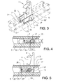
- Figure 3 shows a perspective view of the cargo securing device 1 in its second, raised position where the guiding rail 3 is indicated by stepped lines to make it "transparent” as to clearly show the cargo securing device 1.
- Figures 4 and 5 show a sectional side view along a longitudinal axis of the guiding rail 3 with the device 1 in its first and second position, respectively.
- Figure 6 shows a sectional front view perpendicular to figure 5.
- Figures 3-6 show that the cargo securing device 1 comprises an arm member 9 having an upper portion 13 provided with a hook 11, intended for receiving e.g. a rope, and a lower portion 12 provided with a supporting member 15.
- a pivot member 17 extends from the arm member 9 allowing the arm member 9 to pivot between a first, lower position and a second, raised position, corresponding to the first and second positions of the cargo securing device 1.
- the pivot member 17 has a non-circular cross section that extends over a longer distance D1 in a direction corresponding to a longitudinal axis of the guiding rail 3 than over a distance D2 corresponding to a vertical direction to the guiding rail 3 when the arm member 9 is in its first, lower position, see figure 4.
- the length of the vertical cross section of the pivot member 17 increases as the arm member 9 is pivoted to its second, raised position, which in this embodiment is a vertical position in relation to the guiding rail 3.
- This has the effect that a vertical force can be created while raising the arm member 9 to its second position, which force in this case is used to hold the arm member 9 in its second, raised position and to clamp the cargo securing device 1 between the lower and upper clamping surfaces 8, 10 of the guiding rail 3.
- the cross section of the pivot member 17 expands in a vertical direction as the cargo securing device 1 is raised to its second position.
- the arm member 9 and the pivot member 17 form one integral part.
- the cargo securing device 1 In order to clamp and thereby prevent movement of the cargo securing device 1 when it is in its second, raised position the cargo securing device 1 is equipped with a clamping means 7, 7', 21, 22.
- the clamping means according to the first embodiment of the invention comprises two blocks 7 arranged on each side of the cargo securing device 1.
- Each block 7 is provided with lower clamping parts 21, adapted to interact with the lower clamping surfaces 8 of the guiding rail 3, and upper, wedge-shaped, clamping parts 22 adapted to interact with the wedge-shaped upper clamping surfaces 10 of the guiding rail 3.
- Each block 7 is further provided with an oval opening 24 adapted to receive the pivot member 17, and a slit 25 extending horizontally from the oval opening 24 to a first end 26 of the block 7.
- the slit 25 allows the part of the block 7 provided with the slit 25 to expand vertically as the arm member 9 is raised to its second position.
- the opening 24 is positioned closer to a second end 27 of the block 7 than to the first end 26. This way the length of the slit 25 can be increased, and thereby the vertical expansion capability can be increased, for a given total length of the block 7.
- the cargo securing device 1 When the cargo securing device 1 is in its first, lower position it rests with the lower clamping parts 21 in contact with the lower clamping surfaces 8 of the guiding rail 3 and the upper portion 13 of the arm member 9 in contact with a supporting pin 20. When the cargo securing device 1 is in its second, raised position it is clamped between the lower and upper clamping surfaces 8, 10 of the guiding rail. The upper clamping parts 22 and the upper clamping surfaces 10 interact in a wedging manner as to keep the arm member 9, and thus the cargo securing device 1, in the second, raised position and as to prevent motion of the cargo securing manner along the guiding rail 3, see figure 6.
- a further advantageous effect of a wedge-lock according to the invention is that it stabilizes the construction.
- the guiding rail 3 gives the system an open U-shaped structure but when the cargo securing device 1 is raised to its second position the combination of the clamping means 7 and the guiding rail 3 forms a closed, square structure that has a higher structural strength.
- the wedge angle ⁇ should be chosen as to give a wedging that is sufficiently strong to hold the cargo securing device 1 in place but that does not lock the device 1 so tight that it becomes difficult to turn it back to its lower position. Which angle to choose depends to a great deal on the friction between the parts involved and, thus, on which materials are used for the parts involved. In many cases a suitable value of the wedge angle ⁇ is around 20-30°. With a proper design of the parts involved in the wedging the wedging itself is capable of carrying a considerable load directed along the guiding rail 3, in particular if the load is at least partly directed upwards.
- the components affecting the interaction between the cargo securing device 1 and the guiding rail 3, such as the wedge angle ⁇ , the design of the supporting member 15 and the guiding rail 3, are adapted such that the wedging effect is adequate at the point when the supporting member 15 presses firmly onto the supporting surface 6.
- the components may be adapted as to give an adequate wedging effect when the arm member 9 exhibit a certain angle relative to the guiding rail 3.
- the supporting member 15 is displaced a distance D3 in a longitudinal direction of the guiding rail 3 in relation to the pivot member 17 when the arm member 9 is in its second, raised position.
- This displacement forms a lever function that makes the cargo securing device 1 capable of carrying a relatively heavy load directed along the guiding rail 3 from the pivot member 17 towards the supporting member 15.
- a further lever function is formed due to the vertical distance between the pivot member 17 and the aperture 11. If a force is applied to the cargo securing device 1 via e.g. a rope attached to the aperture 11, and the force is at least partly directed along the guiding rail 3 from the pivot member 17 towards the supporting member 15, i.e. to the right in figure 5, the cargo securing device 1 will not move along the guiding rail 3 but instead be clamped, i.e. wedged, even harder to the guiding rail 3.
- Figure 7 shows a second preferred embodiment of the invention where the upper portion 13 of the arm member 9 on each side is provided with a second supporting member in the form of a plunger 19 and a biasing means (not shown) arranged inside the plunger 19, which biasing means pushes the plunger 19 to an outer position when the arm member 9 is raised sufficiently to allow the plunger 19 to pop-out above the guiding rail 3.
- the plunger 19 With the plunger 19 positioned in its outer position the cargo securing device 1 is further secured in its second, raised position.
- the plunger 19 is displaced a distance in a longitudinal direction of the guiding rail 3 in relation to the pivot member 17 when the arm member 9 is in its second, raised position.
- This displacement forms a lever function that makes the cargo securing device 1 capable of carrying a relatively heavy load directed along the guiding rail 3 from the pivot member 17 towards the plunger 19, i.e. in an oppose direction compared to the case involving the supporting member 15 described above.
- a further lever function is formed due to the vertical distance between the pivot member 17 and the upper portion 13 of the arm member 9, for instance the aperture 11. If a force is applied to the cargo securing device 1 at the upper portion 13 of the arm member 9, for instance caused by an accidental push onto the arm member 9 or caused via e.g. a rope attached to the aperture 11, which in this second embodiment is a closed ring-like aperture, and the force is at least partly directed along the guiding rail 3 from the pivot member 17 towards the plunger 19, i.e.
- the cargo securing device 1 will not, neither in this case, move along the guiding rail 3 but instead be clamped, i.e. wedged, even harder to the guiding rail 3.
- the plunger 19 together with the supporting member 15 makes the cargo securing device 1 capable of carrying a relatively heavy load in any direction.
- the force of the biasing means is preferably not larger than to allow the plunger 19 to be pushed back into the arm member 9 by a simple push of a finger at the time when the cargo securing device 1 is to be moved back to its first, lower position.
- a recess that is adapted to receive the plunger is formed in each block 7, which recess terminates at a rim (not shown) functioning as a support for the plunger 19, and thereby the arm member 9, when the cargo securing device 1 is in its first, lower position.
- the plunger 19 forms the only supporting member of the cargo securing device 1.
- the plunger 19 could be displaced in any of the two longitudinal directions with the upper side 5 of the guiding rail 3 functioning as the supporting surface 6.
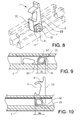
- Figures 8-11 show a third advantageous embodiment of the invention where the clamping means 7', i.e. in this case the lower and upper clamping parts 21, 22, is integrally arranged on the pivot member 17 making the whole cargo securing device 1 consist of only one integral part.
- the arm member 9, with its aperture 11 and supporting member 15, has a similar appearance as in the first two embodiments described above.
- the pivot member 17 is similar to what is described above, i.e. it has a non-circular cross section that extends over a longer distance D1 in a direction corresponding to a longitudinal axis of the guiding rail 3 than over a distance D2 corresponding to a vertical direction to the guiding rail 3 when the arm member 9 is in its first, lower position.
- the supporting member 15 may be provided with a plunger of a type similar to what is described above in relation to the second embodiment.
- a plunger of a type similar to what is described above in relation to the second embodiment.
- Figure 12 shows an example of a cargo securing system wherein two guiding rails 3, each of which are provided with two cargo securing devices 1, have been installed in a floor of a cargo space.
- cargo securing systems may be installed in other surfaces than a horizontal floor.
- the upper clamping surfaces 10 are removed over a certain distance to make it possible to add or remove cargo securing devices 1 to or from the guiding rails 3.
- the inventive cargo securing means described here has several general advantages: it is easy to use, it is flexible since the device 1 can be locked at any position, it can carry a load directed along the rail 3, and it has a relatively uncomplicated structure which reduces production costs.
- the blocks 7 are preferably made out of a plastic material.
- the clamping means may be designed in different ways as long as it allows the securing device 1 to interact in a wedging manner with the guiding rail 3.
- Any clamping means used is preferably associated with the pivot member 17 in the inventive way such that a vertical clamping force is created and transferred from the pivot member 17 to the clamping means 7, 7' during turning of the arm member 9 from the first to the second position.
- a supporting member 15, 19 is not necessary for the invention. However, such a member enhances the capability of carrying a load directed along the guiding rail 3. Further, the displacement of the supporting member 15 forming the distance D3 between the supporting member 15 and the pivot member 17 along the rail 3 may be varied, as well as the distance along which the supporting member 15 and the supporting surface 6 are in contact when the device 1 is in its raised position.
- the distance D3 may be regarded as the distance from the pivot means 17 to a far end of an edge of the supporting member 15, to which edge applied forces will be concentrated.
- a small cam centrally located under the pivot means 17 can not carry any significant load directed along the longitudinal axis of the rail 3.
- the second, raised position of the arm member 9 should be interpreted as a working position, i.e. when a load is applied to the cargo securing device 1.
- the aperture 11 may be designed in various ways, e.g. as a hole, a hook or a snap-hook.
- An opening of a hook should preferably be located at an opposite side of the cargo securing device 1 relative to the supporting member 15 as to show a user in which direction the device 1 is adapted to carry the load.
- the arm member 9 and the pivot member 17 form one integral part.
- the pivot member 17 could be a separate part and the arm member 9 could be provided with an aperture adapted to receive the pivot member 17.
- the second, raised position of the arm member 9 be a non-vertical position, e.g. by extending the lower portion 12 of the arm member 9.
Landscapes
- Engineering & Computer Science (AREA)
- Transportation (AREA)
- Mechanical Engineering (AREA)
- Forklifts And Lifting Vehicles (AREA)
- Fittings On The Vehicle Exterior For Carrying Loads, And Devices For Holding Or Mounting Articles (AREA)
Abstract
Description
- This invention relates to a cargo securing means for fastening of cargo with e.g. ropes during transport. In particular, the invention relates to a cargo securing means arranged in a cargo space in vehicles, such as station cars, vans, trucks and similar.
- In a number of situations it is important to fasten cargo in a secure way during transport to avoid damages or accidents. Cargo securing system should generally be easy to handle, capable of carrying a sufficient load and be out of the way when not in use. Several variants of cargo securing systems for vehicles where e.g. a rope is tied to an attachment point, such as an eye, ring or hook, have been presented in the past. Some of these systems, such as the ones disclosed in
US4741653 andUS6468009 , make use of stationary eyes or rings. Such systems may be advantageous with regard to load-carrying capability but since the point(s) of attachment cannot be moved these systems cannot be adjusted to a particular cargo. Other systems, such as the one disclosed inUS6592310 , make use of an eye or ring that is slidably moveable along a rail to certain positions where it can be locked into holes or slots in the rail. Although such an arrangement is more flexible than a stationary variant, the position of the eye can still not be freely chosen. Further, such systems are prone to be relatively costly to produce.US4460116 discloses a relatively flexible variant where a "tie down/positioning member" can be clamped to the rail at most positions. However, this arrangement appears to have a relatively weak structure in general and it can only carry very small loads in a direction along the rail. Further, the arrangement is rather complex. Among the systems presented in the past there are a number of examples of retractable eyes or rings; inUS4741653 andUS4460116 a pivotally arranged arm can be pivoted between a lower and an upper position; inUS6468009 a "pop-up tie down device" is moveable upwards from a retracted position. - The object of this invention is to provide a flexible cargo securing device and system that exhibit improved clamping properties compared to conventional cargo securing means. This object is achieved by the technical features contained in
claim - The invention concerns a cargo securing device for use with a guiding rail, said cargo securing device comprising an arm member having an upper portion intended for receiving a fastening member, such as a rope, a pivot member allowing the arm member to pivot between a first, lower position in which the cargo securing device is slidably moveable along the guiding rail and a second, raised position in which the upper portion of the arm member at least partly extends above the guiding rail, and a clamping means arranged to interact with clamping surfaces of the guiding rail as to prevent movement of the cargo securing device when the arm member is in its second, raised position. The invention is characterized in that the clamping means comprises a wedge-shaped clamping part adapted to interact in a wedging manner with a corresponding, wedge-shaped clamping surface of the guiding rail.
- Such a design has several advantageous effects. Firstly, a wedged clamping means according to the invention is not just suitable for carrying a load directed in a transverse direction relative to the rail, it is also capable of carrying a significant load directed along the rail. This gives the inventive cargo securing device a higher strength compared to conventional slidable cargo securing means, which in turn makes it safer to use. Additionally, it becomes less important to position the device properly which in turn makes it more easy to use. Secondly, using a wedging effect for holding the device in place makes it possible to give both the securing device and the rail a simple and robust design. One example is that a wedged clamping means stabilizes the construction since an open structure, a U-shaped rail, becomes a closed structure when the wedged clamping means is engaged. Another example is that the cross section of the rail does not have to vary in a longitudinal direction of the rail which simplifies its production. Thirdly, the cargo securing device can be clamped to the guiding rail at any position along a clamping surface extending in a rail which increases the flexibility and makes it further easy to use.
- In a first advantageous embodiment of the invention the clamping means comprises a lower clamping part adapted to interact with a lower clamping surface of the guiding rail and an upper clamping part adapted to interact with an upper clamping surface of the guiding rail. Preferably, the upper clamping part is wedge-shaped. Such a design is simple and by locating the wedge at an upper part of the guiding rail the construction is further stabilized.
- In a second advantageous embodiment of the invention the pivot member has a non-circular cross section that extends a first distance in a first direction and a second distance in a second direction, wherein, when the arm member is positioned in its first, lower position in the guiding rail, the first direction substantially corresponds to a longitudinal axis of the guiding rail and the second direction corresponds to a direction that differ from that of the longitudinal axis of the guiding rail, wherein the first distance is longer than the second distance. Preferably, the second direction is substantially perpendicular to the first direction. An advantageous effect of this non-circular cross section is that a vertical force can be created when turning the arm member from the first to the second position. This force can be used to engage the wedged clamping means.
- In a third advantageous embodiment of the invention the cargo securing device is provided with a supporting member that is adapted to interact with a supporting surface of the guiding rail when the arm member is in its second, raised position, and that the supporting member is displaced a distance in a longitudinal direction of the guiding rail in relation to the pivot member when the arm member is in its second, raised position. An advantageous effect of this design is that a lever function is formed that makes the cargo securing device further capable of carrying a load directed along the guiding rail from the pivot member towards the supporting member. When such a load is applied to the device it is clamped, i.e. wedged, even harder to the rail.
- In the description of the invention given below reference is made to the following figure, in which:
- Figure 1
- shows, in a perspective view, a first preferred embodiment of the inventive cargo securing device installed in a guiding rail in a first, lower position,
- Figure 2
- shows, in a perspective view, the first preferred embodiment of the inventive cargo securing device installed in a guiding rail in a second, raised position,
- Figure 3
- shows, in a perspective view, the first preferred embodiment of the inventive cargo securing device according to figure 2, wherein the guiding rail is indicated by stepped lines,
- Figure 4
- shows, in a sectional side view, the first preferred embodiment of the inventive cargo securing device installed in a guiding rail in the first, lower position,
- Figure 5
- shows, in a sectional side view, the first preferred embodiment of the inventive cargo securing device installed in a guiding rail in the second, raised position,
- Figure 6
- shows, in a front view, the first preferred embodiment of the inventive cargo securing device installed in a guiding rail in the second, raised position,
- Figure 7
- shows, in a perspective view, a second preferred embodiment of the inventive cargo securing device installed in a guiding rail in the second, raised position,
- Figure 8
- shows, in a perspective view, a third preferred embodiment of the inventive cargo securing device in the second, raised position, wherein the guiding rail is indicated by stepped lines,
- Figure 9
- shows, in a sectional side view, the third preferred embodiment of the inventive cargo securing device installed in a guiding rail in a first, lower position,
- Figure 10
- shows, in a sectional side view, the third preferred embodiment of the inventive cargo securing device installed in a guiding rail in a second, raised position,
- Figure 11
- shows, in a front view, the third preferred embodiment of the inventive cargo securing device installed in a guiding rail in a second, raised position, and
- Figure 12
- shows, in a perspective view, a preferred embodiment of a cargo securing system according to the invention.
- A first advantageous embodiment of the inventive
cargo securing device 1 will now be described with reference to figures 1-6. Figures 1 and 2 show thecargo securing device 1 mounted to a guidingrail 3. In figure 1 thecargo securing device 1 is in a first, lower position and in figure 2 it is in a second, raised position. In the first, lower position thecargo securing device 1 is flush with anupper side 5 of the guidingrail 3. A particular advantage of this is that if the guidingrail 3 is positioned such that its upper side is flush with a surrounding surface, e.g. a floor in a cargo space or a luggage compartment, the surface will be free from upwardly protruding parts. Further, in this first, lower position thecargo securing device 1 is slidably moveable along the guiding rail. When thecargo securing device 1 is in the second, raised position as shown in figure 2 anupper portion 13 of anarm member 9 extends above the guidingrail 3 making anopen aperture 11 in the form of a hook accessible for a fastening member, such as a rope. In this second, raised position thecargo securing device 1 is locked by clamping means to the guidingrail 3 as to prevent movement of thecargo securing device 1. Thecargo securing device 1 can be locked at any position along the guidingrail 3. Arecess 2 in alower portion 12 of thearm member 9 facilitates a turning of thecargo securing device 1 to its second, upper position. - As shown in e.g. figures 1, 2 and 6 the guiding
rail 3 has twowalls 4, a supportingsurface 6 in the form of a bottom of the guidingrail 3, as well as lower and upper clamping surfaces 8, 10 protruding from eachwall 4. When thecargo securing device 1 is in its first, lower position it is slidably moveable on thelower clamping surfaces 8 along the guiding rail. When thecargo securing device 1 is raised to its second position it is clamped between the lower and the upper clamping surfaces 8, 10. The lower and upper clamping surfaces 8, 10, of which the latter are wedge-shaped, are adapted to interact with a clamping means 7 associated with thecargo securing device 1. The clamping means 7 is further described below. - Figure 3 shows a perspective view of the
cargo securing device 1 in its second, raised position where the guidingrail 3 is indicated by stepped lines to make it "transparent" as to clearly show thecargo securing device 1. Figures 4 and 5 show a sectional side view along a longitudinal axis of the guidingrail 3 with thedevice 1 in its first and second position, respectively. Figure 6 shows a sectional front view perpendicular to figure 5. - Figures 3-6 show that the
cargo securing device 1 comprises anarm member 9 having anupper portion 13 provided with ahook 11, intended for receiving e.g. a rope, and alower portion 12 provided with a supportingmember 15. Apivot member 17 extends from thearm member 9 allowing thearm member 9 to pivot between a first, lower position and a second, raised position, corresponding to the first and second positions of thecargo securing device 1. Thepivot member 17 has a non-circular cross section that extends over a longer distance D1 in a direction corresponding to a longitudinal axis of the guidingrail 3 than over a distance D2 corresponding to a vertical direction to the guidingrail 3 when thearm member 9 is in its first, lower position, see figure 4. Consequently, the length of the vertical cross section of thepivot member 17 increases as thearm member 9 is pivoted to its second, raised position, which in this embodiment is a vertical position in relation to the guidingrail 3. This has the effect that a vertical force can be created while raising thearm member 9 to its second position, which force in this case is used to hold thearm member 9 in its second, raised position and to clamp thecargo securing device 1 between the lower and upper clamping surfaces 8, 10 of the guidingrail 3. One can say that the cross section of thepivot member 17 expands in a vertical direction as thecargo securing device 1 is raised to its second position. Thearm member 9 and thepivot member 17 form one integral part. - In order to clamp and thereby prevent movement of the
cargo securing device 1 when it is in its second, raised position thecargo securing device 1 is equipped with a clamping means 7, 7', 21, 22. - The clamping means according to the first embodiment of the invention comprises two
blocks 7 arranged on each side of thecargo securing device 1. Eachblock 7 is provided withlower clamping parts 21, adapted to interact with thelower clamping surfaces 8 of the guidingrail 3, and upper, wedge-shaped, clampingparts 22 adapted to interact with the wedge-shaped upper clamping surfaces 10 of the guidingrail 3. Eachblock 7 is further provided with anoval opening 24 adapted to receive thepivot member 17, and aslit 25 extending horizontally from theoval opening 24 to afirst end 26 of theblock 7. Theslit 25 allows the part of theblock 7 provided with theslit 25 to expand vertically as thearm member 9 is raised to its second position. Thus, the vertical force created while raising thearm member 9 to its second position, and which is due to the non-circular cross section of thepivot member 17, acts via the twoblocks 7 onto the lower andupper clamping parts cargo securing device 1 is clamped between the lower and upper clamping surfaces 8, 10 of the guidingrail 3. Theopening 24 is positioned closer to asecond end 27 of theblock 7 than to thefirst end 26. This way the length of theslit 25 can be increased, and thereby the vertical expansion capability can be increased, for a given total length of theblock 7. - When the
cargo securing device 1 is in its first, lower position it rests with thelower clamping parts 21 in contact with thelower clamping surfaces 8 of the guidingrail 3 and theupper portion 13 of thearm member 9 in contact with a supportingpin 20. When thecargo securing device 1 is in its second, raised position it is clamped between the lower and upper clamping surfaces 8, 10 of the guiding rail. Theupper clamping parts 22 and the upper clamping surfaces 10 interact in a wedging manner as to keep thearm member 9, and thus thecargo securing device 1, in the second, raised position and as to prevent motion of the cargo securing manner along the guidingrail 3, see figure 6. A further advantageous effect of a wedge-lock according to the invention, in particular when it is located at the upper part of the guidingrail 3, is that it stabilizes the construction. When thecargo securing device 1 is in its first, lower position the guidingrail 3 gives the system an open U-shaped structure but when thecargo securing device 1 is raised to its second position the combination of the clamping means 7 and the guidingrail 3 forms a closed, square structure that has a higher structural strength. - The wedge angle α (see figure 6) should be chosen as to give a wedging that is sufficiently strong to hold the
cargo securing device 1 in place but that does not lock thedevice 1 so tight that it becomes difficult to turn it back to its lower position. Which angle to choose depends to a great deal on the friction between the parts involved and, thus, on which materials are used for the parts involved. In many cases a suitable value of the wedge angle α is around 20-30°. With a proper design of the parts involved in the wedging the wedging itself is capable of carrying a considerable load directed along the guidingrail 3, in particular if the load is at least partly directed upwards. - As the
cargo securing device 1 is turned on thepivot member 17 towards its second, raised position the movement is, with gradually increasing intensity, counteracted by the wedging effect and finally stopped when the supportingmember 15 interacts with the supportingsurface 6, in this example the bottom, of the guidingrail 3. Preferably, the components affecting the interaction between thecargo securing device 1 and the guidingrail 3, such as the wedge angle α, the design of the supportingmember 15 and the guidingrail 3, are adapted such that the wedging effect is adequate at the point when the supportingmember 15 presses firmly onto the supportingsurface 6. In the absence of a supportingmember 15 the components may be adapted as to give an adequate wedging effect when thearm member 9 exhibit a certain angle relative to the guidingrail 3. - As can be seen in figure 5 the supporting
member 15 is displaced a distance D3 in a longitudinal direction of the guidingrail 3 in relation to thepivot member 17 when thearm member 9 is in its second, raised position. This displacement forms a lever function that makes thecargo securing device 1 capable of carrying a relatively heavy load directed along the guidingrail 3 from thepivot member 17 towards the supportingmember 15. A further lever function is formed due to the vertical distance between thepivot member 17 and theaperture 11. If a force is applied to thecargo securing device 1 via e.g. a rope attached to theaperture 11, and the force is at least partly directed along the guidingrail 3 from thepivot member 17 towards the supportingmember 15, i.e. to the right in figure 5, thecargo securing device 1 will not move along the guidingrail 3 but instead be clamped, i.e. wedged, even harder to the guidingrail 3. - Figure 7 shows a second preferred embodiment of the invention where the
upper portion 13 of thearm member 9 on each side is provided with a second supporting member in the form of aplunger 19 and a biasing means (not shown) arranged inside theplunger 19, which biasing means pushes theplunger 19 to an outer position when thearm member 9 is raised sufficiently to allow theplunger 19 to pop-out above the guidingrail 3. With theplunger 19 positioned in its outer position thecargo securing device 1 is further secured in its second, raised position. In similarity with the supportingmember 15 described above, theplunger 19 is displaced a distance in a longitudinal direction of the guidingrail 3 in relation to thepivot member 17 when thearm member 9 is in its second, raised position. This displacement forms a lever function that makes thecargo securing device 1 capable of carrying a relatively heavy load directed along the guidingrail 3 from thepivot member 17 towards theplunger 19, i.e. in an oppose direction compared to the case involving the supportingmember 15 described above. A further lever function is formed due to the vertical distance between thepivot member 17 and theupper portion 13 of thearm member 9, for instance theaperture 11. If a force is applied to thecargo securing device 1 at theupper portion 13 of thearm member 9, for instance caused by an accidental push onto thearm member 9 or caused via e.g. a rope attached to theaperture 11, which in this second embodiment is a closed ring-like aperture, and the force is at least partly directed along the guidingrail 3 from thepivot member 17 towards theplunger 19, i.e. to the left in figure 7, thecargo securing device 1 will not, neither in this case, move along the guidingrail 3 but instead be clamped, i.e. wedged, even harder to the guidingrail 3. Thus, theplunger 19 together with the supportingmember 15 makes thecargo securing device 1 capable of carrying a relatively heavy load in any direction. The force of the biasing means is preferably not larger than to allow theplunger 19 to be pushed back into thearm member 9 by a simple push of a finger at the time when thecargo securing device 1 is to be moved back to its first, lower position. Preferably, a recess (not shown) that is adapted to receive the plunger is formed in eachblock 7, which recess terminates at a rim (not shown) functioning as a support for theplunger 19, and thereby thearm member 9, when thecargo securing device 1 is in its first, lower position. - In a variant of the invention the
plunger 19 forms the only supporting member of thecargo securing device 1. In such a variant theplunger 19 could be displaced in any of the two longitudinal directions with theupper side 5 of the guidingrail 3 functioning as the supportingsurface 6. - Figures 8-11 show a third advantageous embodiment of the invention where the clamping means 7', i.e. in this case the lower and
upper clamping parts pivot member 17 making the wholecargo securing device 1 consist of only one integral part. Thearm member 9, with itsaperture 11 and supportingmember 15, has a similar appearance as in the first two embodiments described above. In principal also thepivot member 17 is similar to what is described above, i.e. it has a non-circular cross section that extends over a longer distance D1 in a direction corresponding to a longitudinal axis of the guidingrail 3 than over a distance D2 corresponding to a vertical direction to the guidingrail 3 when thearm member 9 is in its first, lower position. The consequences and effects of this design, i.e. the creation of a vertical clamping force when thearm member 9 is raised, are thus principally similar. However, in this embodiment thelower clamping parts 21 and the upper wedge-shapedclamping parts 22 are arranged directly onto thepivot member 17. - In any embodiment the supporting
member 15 may be provided with a plunger of a type similar to what is described above in relation to the second embodiment. By providing the bottom part of therail 3 with holes adapted to receive such a plunger one can further secure thedevice 1 in its second, raised position. However, a drawback of such an arrangement is that the structure of the guidingrail 3 would get more complicated which makes it more costly to produce. - Figure 12 shows an example of a cargo securing system wherein two guiding
rails 3, each of which are provided with twocargo securing devices 1, have been installed in a floor of a cargo space. Naturally, cargo securing systems may be installed in other surfaces than a horizontal floor. In the middle of each guidingrail 3 the upper clamping surfaces 10 are removed over a certain distance to make it possible to add or removecargo securing devices 1 to or from the guiding rails 3. - The inventive cargo securing means described here has several general advantages: it is easy to use, it is flexible since the
device 1 can be locked at any position, it can carry a load directed along therail 3, and it has a relatively uncomplicated structure which reduces production costs. - Various materials, such as steel, aluminium or a plastic material, are suitable both for the
cargo securing device 1 and the guidingrail 3. Which material to choose is mainly a matter of production costs and the magnitude of the loads to be carried. Theblocks 7 are preferably made out of a plastic material. - The invention is not limited by the embodiments described above but can be modified in various ways within the scope of the claims. For instance, the clamping means may be designed in different ways as long as it allows the securing
device 1 to interact in a wedging manner with the guidingrail 3. Any clamping means used is preferably associated with thepivot member 17 in the inventive way such that a vertical clamping force is created and transferred from thepivot member 17 to the clamping means 7, 7' during turning of thearm member 9 from the first to the second position. - It may be noted that a supporting
member rail 3. Further, the displacement of the supportingmember 15 forming the distance D3 between the supportingmember 15 and thepivot member 17 along therail 3 may be varied, as well as the distance along which the supportingmember 15 and the supportingsurface 6 are in contact when thedevice 1 is in its raised position. The distance D3 may be regarded as the distance from the pivot means 17 to a far end of an edge of the supportingmember 15, to which edge applied forces will be concentrated. In contrast to the invention, a small cam centrally located under the pivot means 17 can not carry any significant load directed along the longitudinal axis of therail 3. - Moreover, the second, raised position of the
arm member 9 should be interpreted as a working position, i.e. when a load is applied to thecargo securing device 1. - Further, the
aperture 11 may be designed in various ways, e.g. as a hole, a hook or a snap-hook. An opening of a hook should preferably be located at an opposite side of thecargo securing device 1 relative to the supportingmember 15 as to show a user in which direction thedevice 1 is adapted to carry the load. - Moreover, it is not necessary that the
arm member 9 and thepivot member 17 form one integral part. Thepivot member 17 could be a separate part and thearm member 9 could be provided with an aperture adapted to receive thepivot member 17. - It is further possible to let the second, raised position of the
arm member 9 be a non-vertical position, e.g. by extending thelower portion 12 of thearm member 9. - An alternative to the described embodiments is to position the supporting
member 15 directly or indirectly onto thepivot member 17 and use thelower clamping surfaces 8 as the supportingsurface 6. As mentioned in relation to the second embodiment above also theupper side 5 of therail 3 can be used as supportingsurface 6.
Claims (19)
- Cargo securing device (1) for use with a guiding rail (3), said cargo securing device (1) comprising- an arm member (9) having an upper portion (13) intended for receiving a fastening member, such as a rope,- a pivot member (17) allowing the arm member (9) to pivot between a first, lower position in which the cargo securing device (1) is slidably moveable along the guiding rail (3) and a second, raised position in which the upper portion (13) of the arm member (9) at least partly extends above the guiding rail (3), and- a clamping means (7, 7', 21, 22) arranged to interact with clamping surfaces (8, 10) of the guiding rail (3) as to prevent movement of the cargo securing device (1) when the arm member (9) is in its second, raised position,characterized in
that the clamping means comprises a wedge-shaped clamping part (22) adapted to interact in a wedging manner with a corresponding, wedge-shaped clamping surface (10) of the guiding rail (3). - Cargo securing device (1) according to claim 1,
characterized in
that the clamping means comprises a lower clamping part (21) adapted to interact with a lower clamping surface (8) of the guiding rail (3) and an upper clamping part (22) adapted to interact with an upper clamping surface (10) of the guiding rail (3). - Cargo securing device (1) according to claim 2,
characterized in
that the upper clamping part (22) is wedge-shaped. - Cargo securing device (1) according to claim 2 or 3,
characterized in
that the clamping means comprises a block (7) provided with said lower and upper clamping parts (21, 22), said block (7) further being provided with an opening (24) adapted to receive the pivot member (17), and a slit (25) extending from the opening (24) to a first end (26) of the block (7). - Cargo securing device (1) according to claim 2 or 3,
characterized in
that the lower and upper clamping parts (21, 22) are arranged onto the pivot member (17). - Cargo securing device (1) according to claim 5,
characterized in
that the lower and upper clamping parts (21, 22) form an integral part of the pivot member (17). - Cargo securing device (1) according to anyone of the above claims,
characterized in
that the pivot member (17) has a non-circular cross section that extends a first distance (D1) in a first direction and a second distance (D2) in a second direction, wherein, when the arm member (9) is positioned in its first, lower position in the guiding rail (3), the first direction substantially corresponds to a longitudinal axis of the guiding rail (3) and the second direction corresponds to a direction that differ from that of the longitudinal axis of the guiding rail (3), wherein the first distance (D1) is longer than the second distance (D2). - Cargo securing device (1) according to claim 7,
characterized in
that the second direction is substantially perpendicular to the first direction. - Cargo securing device (1) according to anyone of the above claims,
characterized in
that the pivot member (17) forms an integral part of the arm member (9). - Cargo securing device (1) according to anyone of the above claims,
characterized in
that the cargo securing device (1) is provided with a supporting member (15, 19) that is adapted to interact with a supporting surface (5, 6) of the guiding rail (3) when the arm member (9) is in its second, raised position, and that the supporting member (15, 19) is displaced a distance (D3) in a longitudinal direction of the guiding rail (3) in relation to the pivot member (17) when the arm member (9) is in its second, raised position. - Cargo securing device (1) according to claim 10,
characterized in
that the supporting member (15) is arranged on a lower portion (12) of the arm member (9). - Cargo securing device (1) according to claim 10 or 11,
characterized in
that the supporting member (15) forms an integral part of the arm member (9). - Cargo securing device (1) according to claim 10,
characterized in
that the supporting member (15) is arranged on the pivot member (17). - Cargo securing device (1) according to claim 10 or 13,
characterized in
that the supporting member (15) forms an integral part of the pivot member (17). - Cargo securing device (1) according to anyone of claims 10 to 14,
characterized in
that the supporting member (15, 19) is adapted to interact with a supporting surface (6) that is located below, in relation to an upper side (5) of the guiding rail (3), a level at which the pivot member (17) is located. - Cargo securing device (1) according to anyone of claims 10 to 14,
characterized in
that the supporting member (15, 19) is adapted to interact with a supporting surface (6) that also forms an upper side (5) of the guiding rail (3). - Cargo securing device (1) according to anyone of the above claims,
characterized in
that the upper portion (13) of the arm member (9) is provided with an aperture (11) for receiving the fastening member. - Cargo securing system,
characterized in
that it comprises a cargo securing device (1) according to anyone of claims 1 to 9 above, and a guiding rail comprising clamping surfaces (8, 10). - Cargo securing system,
characterized in
that it comprises a cargo securing device (1) according to anyone of claims 1 to 17 above, and a guiding rail comprising clamping surfaces (8, 10) and a supporting surface (5, 6).
Priority Applications (1)
| Application Number | Priority Date | Filing Date | Title |
|---|---|---|---|
| EP20050105403 EP1733921B1 (en) | 2005-06-17 | 2005-06-17 | Cargo securing device |
Applications Claiming Priority (1)
| Application Number | Priority Date | Filing Date | Title |
|---|---|---|---|
| EP20050105403 EP1733921B1 (en) | 2005-06-17 | 2005-06-17 | Cargo securing device |
Publications (2)
| Publication Number | Publication Date |
|---|---|
| EP1733921A1 true EP1733921A1 (en) | 2006-12-20 |
| EP1733921B1 EP1733921B1 (en) | 2012-01-25 |
Family
ID=35134756
Family Applications (1)
| Application Number | Title | Priority Date | Filing Date |
|---|---|---|---|
| EP20050105403 Expired - Lifetime EP1733921B1 (en) | 2005-06-17 | 2005-06-17 | Cargo securing device |
Country Status (1)
| Country | Link |
|---|---|
| EP (1) | EP1733921B1 (en) |
Cited By (6)
| Publication number | Priority date | Publication date | Assignee | Title |
|---|---|---|---|---|
| EP2436562A1 (en) * | 2010-10-04 | 2012-04-04 | Advanced Comfort Systems France SAS - ACS France | Hinged device for holding at least one object inside a vehicle luggage compartment |
| DE102014225824A1 (en) * | 2014-12-15 | 2016-06-16 | Bos Gmbh & Co. Kg | Load bay load rail system for a motor vehicle |
| CN109850042A (en) * | 2019-03-14 | 2019-06-07 | 重庆张红机械制造有限公司 | Electric flatbed tricycle |
| US20200269369A1 (en) * | 2019-02-25 | 2020-08-27 | Robert N. Poole | Work surface mountable t-track |
| WO2020176490A1 (en) * | 2019-02-25 | 2020-09-03 | Poole Robert N | Work surface mountable t-track |
| FR3154960A1 (en) * | 2023-11-08 | 2025-05-09 | Stellantis Auto Sas | Mobile load transport device with simplified holding system |
Citations (9)
| Publication number | Priority date | Publication date | Assignee | Title |
|---|---|---|---|---|
| US3722910A (en) * | 1971-04-21 | 1973-03-27 | H Heckenlaible | Hook unit for pickup trucks |
| US4460116A (en) | 1981-12-30 | 1984-07-17 | Bott John Anthony | Vehicle article carrier |
| EP0159394A1 (en) * | 1983-09-14 | 1985-10-30 | ANCRA Jungfalk GmbH | Lashing track for securing merchandise to vehicles |
| US4741653A (en) | 1986-10-30 | 1988-05-03 | Joyce Catherine Schmidt | Cargo securing means |
| FR2675442A1 (en) * | 1991-04-18 | 1992-10-23 | Boni Sa | Device making it possible to instal, without tooling, fastening points for securely positioning and anchoring a load |
| US6164882A (en) * | 1999-12-10 | 2000-12-26 | Jirosel Corp. | Snowmobile tie-down mechanism for a trailer |
| EP1108608A1 (en) * | 1999-12-13 | 2001-06-20 | Renault | Tie down device on a rail |
| US20010010786A1 (en) | 1999-08-11 | 2001-08-02 | Elwell James P. | Pop-up tie down device and method for using same |
| US20020084338A1 (en) | 2000-06-12 | 2002-07-04 | Hyp Eric D. | Tie-down hoop |
-
2005
- 2005-06-17 EP EP20050105403 patent/EP1733921B1/en not_active Expired - Lifetime
Patent Citations (9)
| Publication number | Priority date | Publication date | Assignee | Title |
|---|---|---|---|---|
| US3722910A (en) * | 1971-04-21 | 1973-03-27 | H Heckenlaible | Hook unit for pickup trucks |
| US4460116A (en) | 1981-12-30 | 1984-07-17 | Bott John Anthony | Vehicle article carrier |
| EP0159394A1 (en) * | 1983-09-14 | 1985-10-30 | ANCRA Jungfalk GmbH | Lashing track for securing merchandise to vehicles |
| US4741653A (en) | 1986-10-30 | 1988-05-03 | Joyce Catherine Schmidt | Cargo securing means |
| FR2675442A1 (en) * | 1991-04-18 | 1992-10-23 | Boni Sa | Device making it possible to instal, without tooling, fastening points for securely positioning and anchoring a load |
| US20010010786A1 (en) | 1999-08-11 | 2001-08-02 | Elwell James P. | Pop-up tie down device and method for using same |
| US6164882A (en) * | 1999-12-10 | 2000-12-26 | Jirosel Corp. | Snowmobile tie-down mechanism for a trailer |
| EP1108608A1 (en) * | 1999-12-13 | 2001-06-20 | Renault | Tie down device on a rail |
| US20020084338A1 (en) | 2000-06-12 | 2002-07-04 | Hyp Eric D. | Tie-down hoop |
Cited By (8)
| Publication number | Priority date | Publication date | Assignee | Title |
|---|---|---|---|---|
| EP2436562A1 (en) * | 2010-10-04 | 2012-04-04 | Advanced Comfort Systems France SAS - ACS France | Hinged device for holding at least one object inside a vehicle luggage compartment |
| FR2965524A1 (en) * | 2010-10-04 | 2012-04-06 | Acs France Sas | JOINT DEVICE FOR RETAINING AT LEAST ONE OBJECT IN A VEHICLE BOX. |
| DE102014225824A1 (en) * | 2014-12-15 | 2016-06-16 | Bos Gmbh & Co. Kg | Load bay load rail system for a motor vehicle |
| DE102014225824B4 (en) | 2014-12-15 | 2021-07-29 | Bos Gmbh & Co. Kg | Loading space load rail system for a motor vehicle |
| US20200269369A1 (en) * | 2019-02-25 | 2020-08-27 | Robert N. Poole | Work surface mountable t-track |
| WO2020176490A1 (en) * | 2019-02-25 | 2020-09-03 | Poole Robert N | Work surface mountable t-track |
| CN109850042A (en) * | 2019-03-14 | 2019-06-07 | 重庆张红机械制造有限公司 | Electric flatbed tricycle |
| FR3154960A1 (en) * | 2023-11-08 | 2025-05-09 | Stellantis Auto Sas | Mobile load transport device with simplified holding system |
Also Published As
| Publication number | Publication date |
|---|---|
| EP1733921B1 (en) | 2012-01-25 |
Similar Documents
| Publication | Publication Date | Title |
|---|---|---|
| US6955511B1 (en) | Retractable anchor device and method of mounting the anchor device | |
| US5782391A (en) | Vehicle roof rack loading mechanism | |
| US8028875B2 (en) | Vehicle article carrier having swing in place cross bars | |
| US6182876B1 (en) | Attachment mechanisms for securing utility racks to vehicles | |
| US6575516B2 (en) | Tailgate ramp and load locking accessories for a pickup truck | |
| US20080253855A1 (en) | Device for fastening cargo in a transportation means | |
| EP3594065B1 (en) | Load carrier | |
| US8475096B2 (en) | Tonneau cover cargo containment track rail system | |
| US6464437B1 (en) | Push-down pop-up tie mechanism | |
| US20090080995A1 (en) | Vehicle cargo arrangement | |
| US6974164B2 (en) | Latch device for securing cargo containers | |
| CA2600671A1 (en) | Slide out cargo floor | |
| US11414005B2 (en) | Offset fastener | |
| CA2478064A1 (en) | Supplemental restraint for auto-rack railroad car restraint system | |
| US6168360B1 (en) | Tiedown hook and rail | |
| US9896018B2 (en) | Locking cargo tie-down | |
| EP1733921B1 (en) | Cargo securing device | |
| EP2065257B1 (en) | A roof bar for a motor vehicle | |
| US20070224010A1 (en) | Locking device for securing loads | |
| EP0949112A1 (en) | Modular anchoring system in an automotive vehicle passenger compartment | |
| KR200412701Y1 (en) | Car Bike Carrier | |
| US7040683B1 (en) | Truck bed extender | |
| WO2000030895A1 (en) | Load carrying system for vehicles | |
| US7121778B2 (en) | Device to secure cargo | |
| KR200147030Y1 (en) | Towing hook of a car |
Legal Events
| Date | Code | Title | Description |
|---|---|---|---|
| PUAI | Public reference made under article 153(3) epc to a published international application that has entered the european phase |
Free format text: ORIGINAL CODE: 0009012 |
|
| AK | Designated contracting states |
Kind code of ref document: A1 Designated state(s): AT BE BG CH CY CZ DE DK EE ES FI FR GB GR HU IE IS IT LI LT LU MC NL PL PT RO SE SI SK TR |
|
| AX | Request for extension of the european patent |
Extension state: AL BA HR LV MK YU |
|
| 17P | Request for examination filed |
Effective date: 20070607 |
|
| AKX | Designation fees paid |
Designated state(s): DE GB SE |
|
| 17Q | First examination report despatched |
Effective date: 20070911 |
|
| GRAP | Despatch of communication of intention to grant a patent |
Free format text: ORIGINAL CODE: EPIDOSNIGR1 |
|
| RAP1 | Party data changed (applicant data changed or rights of an application transferred) |
Owner name: VOLVO CAR CORPORATION |
|
| GRAS | Grant fee paid |
Free format text: ORIGINAL CODE: EPIDOSNIGR3 |
|
| GRAA | (expected) grant |
Free format text: ORIGINAL CODE: 0009210 |
|
| AK | Designated contracting states |
Kind code of ref document: B1 Designated state(s): DE GB SE |
|
| REG | Reference to a national code |
Ref country code: GB Ref legal event code: FG4D |
|
| REG | Reference to a national code |
Ref country code: DE Ref legal event code: R096 Ref document number: 602005032359 Country of ref document: DE Effective date: 20120322 |
|
| REG | Reference to a national code |
Ref country code: SE Ref legal event code: TRGR |
|
| PLBE | No opposition filed within time limit |
Free format text: ORIGINAL CODE: 0009261 |
|
| STAA | Information on the status of an ep patent application or granted ep patent |
Free format text: STATUS: NO OPPOSITION FILED WITHIN TIME LIMIT |
|
| 26N | No opposition filed |
Effective date: 20121026 |
|
| REG | Reference to a national code |
Ref country code: DE Ref legal event code: R097 Ref document number: 602005032359 Country of ref document: DE Effective date: 20121026 |
|
| PGFP | Annual fee paid to national office [announced via postgrant information from national office to epo] |
Ref country code: SE Payment date: 20190620 Year of fee payment: 15 |
|
| PGFP | Annual fee paid to national office [announced via postgrant information from national office to epo] |
Ref country code: GB Payment date: 20190613 Year of fee payment: 15 |
|
| GBPC | Gb: european patent ceased through non-payment of renewal fee |
Effective date: 20200617 |
|
| PG25 | Lapsed in a contracting state [announced via postgrant information from national office to epo] |
Ref country code: GB Free format text: LAPSE BECAUSE OF NON-PAYMENT OF DUE FEES Effective date: 20200617 |
|
| PG25 | Lapsed in a contracting state [announced via postgrant information from national office to epo] |
Ref country code: SE Free format text: LAPSE BECAUSE OF NON-PAYMENT OF DUE FEES Effective date: 20200618 |
|
| REG | Reference to a national code |
Ref country code: SE Ref legal event code: EUG |
|
| PGFP | Annual fee paid to national office [announced via postgrant information from national office to epo] |
Ref country code: DE Payment date: 20230523 Year of fee payment: 19 |
|
| P01 | Opt-out of the competence of the unified patent court (upc) registered |
Effective date: 20231212 |
|
| REG | Reference to a national code |
Ref country code: DE Ref legal event code: R119 Ref document number: 602005032359 Country of ref document: DE |
|
| PG25 | Lapsed in a contracting state [announced via postgrant information from national office to epo] |
Ref country code: DE Free format text: LAPSE BECAUSE OF NON-PAYMENT OF DUE FEES Effective date: 20250101 |