EP1733814A1 - A roll and a spring therefor - Google Patents
A roll and a spring therefor Download PDFInfo
- Publication number
- EP1733814A1 EP1733814A1 EP06445034A EP06445034A EP1733814A1 EP 1733814 A1 EP1733814 A1 EP 1733814A1 EP 06445034 A EP06445034 A EP 06445034A EP 06445034 A EP06445034 A EP 06445034A EP 1733814 A1 EP1733814 A1 EP 1733814A1
- Authority
- EP
- European Patent Office
- Prior art keywords
- spring
- roll
- rings
- slot
- ring
- Prior art date
- Legal status (The legal status is an assumption and is not a legal conclusion. Google has not performed a legal analysis and makes no representation as to the accuracy of the status listed.)
- Granted
Links
- 239000013013 elastic material Substances 0.000 claims abstract 2
- 125000006850 spacer group Chemical group 0.000 claims description 7
- 239000002184 metal Substances 0.000 claims description 4
- 230000004323 axial length Effects 0.000 claims 3
- 239000000463 material Substances 0.000 description 5
- 229910000831 Steel Inorganic materials 0.000 description 3
- 230000001419 dependent effect Effects 0.000 description 3
- 238000006073 displacement reaction Methods 0.000 description 3
- 239000010959 steel Substances 0.000 description 3
- 238000004519 manufacturing process Methods 0.000 description 2
- 230000015572 biosynthetic process Effects 0.000 description 1
- 238000005553 drilling Methods 0.000 description 1
- 230000005489 elastic deformation Effects 0.000 description 1
- 230000033001 locomotion Effects 0.000 description 1
- 238000003754 machining Methods 0.000 description 1
- 238000003801 milling Methods 0.000 description 1
- 238000012986 modification Methods 0.000 description 1
- 230000004048 modification Effects 0.000 description 1
Images

Classifications
-
- F—MECHANICAL ENGINEERING; LIGHTING; HEATING; WEAPONS; BLASTING
- F16—ENGINEERING ELEMENTS AND UNITS; GENERAL MEASURES FOR PRODUCING AND MAINTAINING EFFECTIVE FUNCTIONING OF MACHINES OR INSTALLATIONS; THERMAL INSULATION IN GENERAL
- F16C—SHAFTS; FLEXIBLE SHAFTS; ELEMENTS OR CRANKSHAFT MECHANISMS; ROTARY BODIES OTHER THAN GEARING ELEMENTS; BEARINGS
- F16C13/00—Rolls, drums, discs, or the like; Bearings or mountings therefor
-
- B—PERFORMING OPERATIONS; TRANSPORTING
- B21—MECHANICAL METAL-WORKING WITHOUT ESSENTIALLY REMOVING MATERIAL; PUNCHING METAL
- B21B—ROLLING OF METAL
- B21B27/00—Rolls, roll alloys or roll fabrication; Lubricating, cooling or heating rolls while in use
- B21B27/02—Shape or construction of rolls
- B21B27/03—Sleeved rolls
- B21B27/035—Rolls for bars, rods, rounds, tubes, wire or the like
Definitions
- this invention relates to a roll of the type that comprises a roll shaft and two axially spaced-apart stop rings, one of which is fixed and the other one is a lock nut, a plurality of other rings in the form of roll rings and/or spacer rings being mounted between the stop rings, as well as at least one spring that has two axially spaced-apart ends.
- the invention in a second aspect, relates to a spring as such.
- the present invention aims at obviating the spring prestress problems that are involved with previously known roll and springs associated thereto, and at providing an improved roll and spring, respectively. Therefore, a primary object of the invention is to provide a spring suitable for combi rolls that is powerful and has a long service life, in so far that it should be able to work in a powerful way for a long time without slackening. An additional object is to provide a spring that has a short stroke or spring length and in spite of this generates considerable, dynamic spring forces. An additional object of the invention is to provide a spring which has a moderate axial extension in order not to intrude unnecessarily on the available space (roll width) between the stop rings. Furthermore, the invention aims at providing a spring that guarantees surface contact with adjacent rings rather than line contact.
- At least the primary object is attained - in a first aspect - by a roll of the type defined in the independent claim 1.
- An advantageous embodiment of the roll according to the invention is further defined in the dependent claim 2.
- the invention relates to a roll spring as such.
- the vital features of this spring are found in the independent claim 3.
- Preferred embodiments of the spring according to the invention are further defined in the dependent claims 4-10.
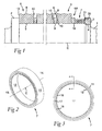
- reference numeral 1 designates a drivable roll shaft that has a rotationally symmetrical basic shape, and is provided with two axially spaced-apart stop rings 2, 3, one of which, viz. the ring 2, is fixed, while the other one is a lock nut 3.
- the fixed stop ring 2 may either be made in the form of a ring-shaped shoulder of the shaft, as shown in Fig. 1, or be made in the form of a separate ring (not shown) which is detachably mounted on the shaft, although axially locked in relation to the same.
- the detachable lock nut 3 is connected to the shaft via a threaded joint 4 which includes a female thread on the inside of the nut ring and male thread on the shaft.
- a set of detachable rings is arranged, of which certain are roll rings 5, and others are spacer rings 6.
- a special spacer ring 6A is inserted between a roll ring 5 and a ring-shaped spring designated 7.
- all rings have a rotationally symmetrical, more precisely cylindrical, basic shape, so far that they are delimited between, on one hand, external and internal cylinder surfaces 8, 9 and, on the other hand, opposite, planar end surfaces 10.
- the cylinder surfaces 8, 9, which usually are machined by turning, are defined by the centre axis C of the shaft.
- Figs. 2-4 illustrate the nature of the spring 7 in detail.
- the spring 7 has a rotationally symmetrical basic shape determined by external and internal cylinder surfaces 11, 12 concentric with the centre axis C (in the mounted state, the centre axis of the spring ring coincides with the centre axis of the roll shaft 1). Furthermore, the spring body is delimited by opposite, axially spaced-apart ends 13, 14 that are generally ring-shaped. In order to provide conceptual clarity in the description to follow, the ends are referred to as front and rear, respectively. However, these are related only to Fig. 2, where the end 13 is shown in front and the end 14 at the rear.
- a number of slots or gaps 15 opens in the front end 13 of the spring body, which slots extend towards the rear end 14, without reaching up to the same.
- the number of forward opening slots 15 amounts to two. In such a way, the slots 15 separate in total three different laminae 16, 17, 18, each one of which has a free end surface 19, 20, 21.
- Each slot 15 is delimited by two spaced-apart cylinder surfaces 22, 23 which are concentric and end in a bottom 24.
- two similar, second slots 25 open, which extend towards the front end 13, without reaching up to the same.
- the slots 25 separate three rearward-facing laminae 26, 27, 28.
- the end surfaces of the same three laminae are designated 29, 30, 31.
- the slots 25 are defined by cylindrical, concentric limiting surfaces 32, 33 which end in bottoms 34.
- L1 designates the total length or axial extension of the spring body
- L2 designates the length or depth of the individual slot 25.
- all four slots i.e., also the slots 15, have one and the same depth L2.
- the depth L2 should amount to at least 60 % of the total length L1 of the spring body.
- the slot depth L2 should not exceed 90 % of the length L1.
- the individual slot 15 is advantageously located about halfway between the two adjacent slots 25.
- the two outer forward-facing laminae 17, 18 have a material thickness (such as this is determined by the difference between the outer diameter and the inner diameter) twice as large as the corresponding material thickness of the inner forward-facing lamina 16.
- the outer rearward-facing lamina 28 has a material thickness that is half as large as the material thickness of the two inner rearward-facing laminae 26, 27.
- one of the end surfaces of each end of the spring body is axially displaced in relation to the end surface of one or more adjacent laminae.
- the end surface 19 of the intermediate forward-facing lamina 16 is axially displaced (forwardly) in relation to the end surface 20 of the nearest lamina 17.
- the end surface 20 of the lamina 17 is axially displaced forwardly in relation to the end surface 21 of the outermost lamina 18.
- the displacements are designated S1 and S2, respectively.
- these may be within the range of 0,2-2 mm, suitably 0,4-1 mm, on the assumption that the spring body has such dimensions that the difference between the outer diameter D1 and the inner diameter D2 is within the range of 20-50 mm, and the total length L1 within the range of 60-120 mm.
- the end surfaces 29, 30, 31 are axially displaced in steps in relation to each other with S1, S2.
- the displacements S1, S2 at the end 14 may be mutually equally large, as well as equally large as the corresponding S1, S2 at the opposite end 13.
- At least those end surfaces 19, 31 that form the contact surfaces of the spring body against adjacent rings in the roll are made having planar shape.
- the other end surfaces 20, 21; 29, 30 may be planar.
- the described spring body may advantageously be manufactured in one single piece of, for instance, metal, such as steel.
- metal such as steel.
- machining turning, milling and/or hollow drilling
- a ring-shaped blank of, for instance, steel having suitable elasticity properties it is accordingly possible to produce springs that can provide for highly varying demands concerning spring force, spring length, dimensions, etc.
- the spring 7 is shown mounted between the lock nut 3 and the spacer ring 6A, the planar end surface 31 of the spring being pressed against the likewise planar end surface of the inside of the lock nut 3, while the end surface 19 is pressed against the planar end surface of the spacer ring 6A.
- the spring is supplied with counter-directed axial forces that generate labyrinth-shaped trains of spring forces inside the spring body, more precisely between the end surfaces 19, 31, the spring body being compressed by elastic deformation of the same, above all in the U-shaped portions of the laminae adjacent to the slot bottoms 24, 34.
- a plurality of tightening devices 35 e.g., screws
- tightening devices 35 may be utilized in order not only to initially adjust the spring-tension, but also if required readjust the same.
- the placing of the spring in the set of rings is not limited to the immediate vicinity of the lock nut.
- the essential thing is that the spring is active in the set of rings of the roll shaft.
- the spring itself may be realized in another way than in the form of a body shaped in one single piece.
- the number of laminae, and the number of separating slots, respectively may be varied most considerably within the scope of the subsequent claims. However, at least one slot has to open in one end of the spring body and at least one slot in the opposite end.
Landscapes
- Engineering & Computer Science (AREA)
- Mechanical Engineering (AREA)
- Physics & Mathematics (AREA)
- Geometry (AREA)
- General Engineering & Computer Science (AREA)
- Springs (AREA)
- Rolls And Other Rotary Bodies (AREA)
- Reduction Rolling/Reduction Stand/Operation Of Reduction Machine (AREA)
- Spinning Or Twisting Of Yarns (AREA)
- Mechanical Pencils And Projecting And Retracting Systems Therefor, And Multi-System Writing Instruments (AREA)
- Massaging Devices (AREA)
Abstract
Description
- In a first aspect, this invention relates to a roll of the type that comprises a roll shaft and two axially spaced-apart stop rings, one of which is fixed and the other one is a lock nut, a plurality of other rings in the form of roll rings and/or spacer rings being mounted between the stop rings, as well as at least one spring that has two axially spaced-apart ends.
- In a second aspect, the invention relates to a spring as such.
- In rolls of the kind generally mentioned above - which by those skilled in the art are referred to as combi rolls - it is important that the roll rings are kept pressed in close contact against occurring spacer rings in order for the rings not to slip in relation to each other. For this purpose, solely the lock nut itself is inadequate, and therefore it is necessary to arrange, in the set of rings, at least one powerful spring, which for a long time continuously can apply a spring prestress to the rings. For this purpose, Belleville springs, among others, have previously been used (see, for instance,
US 5735788 ). However, for many different reasons, the use of Belleville springs has not been successful. One of these reasons is that such springs have a tendency to slacken or be fatigued too fast. Another reason is that a Belleville spring only has line contact with adjacent rings and not surface contact. - The present invention aims at obviating the spring prestress problems that are involved with previously known roll and springs associated thereto, and at providing an improved roll and spring, respectively. Therefore, a primary object of the invention is to provide a spring suitable for combi rolls that is powerful and has a long service life, in so far that it should be able to work in a powerful way for a long time without slackening. An additional object is to provide a spring that has a short stroke or spring length and in spite of this generates considerable, dynamic spring forces. An additional object of the invention is to provide a spring which has a moderate axial extension in order not to intrude unnecessarily on the available space (roll width) between the stop rings. Furthermore, the invention aims at providing a spring that guarantees surface contact with adjacent rings rather than line contact.
- According to the invention, at least the primary object is attained - in a first aspect - by a roll of the type defined in the
independent claim 1. An advantageous embodiment of the roll according to the invention is further defined in thedependent claim 2. - In another aspect, the invention relates to a roll spring as such. The vital features of this spring are found in the independent claim 3. Preferred embodiments of the spring according to the invention are further defined in the dependent claims 4-10.
- In the drawings:
- Fig. 1
- is a partial longitudinal section through a combi roll in which a spring according to the invention is included,
- Fig. 2
- is a perspective view of solely the spring,
- Fig. 3
- is an end view of the spring, and
- Fig. 4
- is an enlarged longitudinal section A-A in Fig. 3.
- In Fig. 1,
reference numeral 1 designates a drivable roll shaft that has a rotationally symmetrical basic shape, and is provided with two axially spaced-apart stop rings 2, 3, one of which, viz. thering 2, is fixed, while the other one is a lock nut 3. The fixedstop ring 2 may either be made in the form of a ring-shaped shoulder of the shaft, as shown in Fig. 1, or be made in the form of a separate ring (not shown) which is detachably mounted on the shaft, although axially locked in relation to the same. The detachable lock nut 3 is connected to the shaft via a threaded joint 4 which includes a female thread on the inside of the nut ring and male thread on the shaft. - Between the
stop rings 2, 3 a set of detachable rings is arranged, of which certain areroll rings 5, and others arespacer rings 6. Aspecial spacer ring 6A is inserted between aroll ring 5 and a ring-shaped spring designated 7. Generally, all rings have a rotationally symmetrical, more precisely cylindrical, basic shape, so far that they are delimited between, on one hand, external andinternal cylinder surfaces 8, 9 and, on the other hand, opposite,planar end surfaces 10. Thecylinder surfaces 8, 9, which usually are machined by turning, are defined by the centre axis C of the shaft. - Figs. 2-4 illustrate the nature of the
spring 7 in detail. - In Fig. 2, it is seen that also the
spring 7 has a rotationally symmetrical basic shape determined by external andinternal cylinder surfaces ends end 13 is shown in front and theend 14 at the rear. - As is seen in Fig. 4, a number of slots or
gaps 15 opens in thefront end 13 of the spring body, which slots extend towards therear end 14, without reaching up to the same. In the example, the number offorward opening slots 15 amounts to two. In such a way, theslots 15 separate in total threedifferent laminae free end surface - Each
slot 15 is delimited by two spaced-apart cylinder surfaces bottom 24. - In the
rear end 14 of the spring body, two similar,second slots 25 open, which extend towards thefront end 13, without reaching up to the same. In the same way as theslots 15, theslots 25 separate three rearward-facinglaminae slots 25 are defined by cylindrical, concentriclimiting surfaces bottoms 34. - In Fig. 4, L1 designates the total length or axial extension of the spring body, while L2 designates the length or depth of the
individual slot 25. Advantageously, all four slots, i.e., also theslots 15, have one and the same depth L2. Although it is possible to vary the depth of the slots within fairly wide limits, and thereby vary the properties of the spring, the depth L2 should amount to at least 60 % of the total length L1 of the spring body. On the other hand, the slot depth L2 should not exceed 90 % of the length L1. - The
individual slot 15 is advantageously located about halfway between the twoadjacent slots 25. The two outer forward-facinglaminae lamina 16. Conversely, the outer rearward-facinglamina 28 has a material thickness that is half as large as the material thickness of the two inner rearward-facinglaminae - In accordance with a vital feature of the invention, one of the end surfaces of each end of the spring body is axially displaced in relation to the end surface of one or more adjacent laminae. Thus, as is clearly seen in Fig. 4, the
end surface 19 of the intermediate forward-facinglamina 16 is axially displaced (forwardly) in relation to theend surface 20 of thenearest lamina 17. Furthermore, in the example, theend surface 20 of thelamina 17 is axially displaced forwardly in relation to theend surface 21 of theoutermost lamina 18. In the unloaded state of the spring, such as shown in Fig. 4, the displacements are designated S1 and S2, respectively. In practice, these may be within the range of 0,2-2 mm, suitably 0,4-1 mm, on the assumption that the spring body has such dimensions that the difference between the outer diameter D1 and the inner diameter D2 is within the range of 20-50 mm, and the total length L1 within the range of 60-120 mm. - In an analogous (although reversed) way, the end surfaces 29, 30, 31 are axially displaced in steps in relation to each other with S1, S2. In practice, the displacements S1, S2 at the
end 14 may be mutually equally large, as well as equally large as the corresponding S1, S2 at theopposite end 13. - According to the invention, at least those end surfaces 19, 31 that form the contact surfaces of the spring body against adjacent rings in the roll are made having planar shape. For practical reasons of manufacture, also the other end surfaces 20, 21; 29, 30 may be planar.
- The described spring body may advantageously be manufactured in one single piece of, for instance, metal, such as steel. By machining (turning, milling and/or hollow drilling) a ring-shaped blank of, for instance, steel having suitable elasticity properties, it is accordingly possible to produce springs that can provide for highly varying demands concerning spring force, spring length, dimensions, etc.
- In Fig. 1, the
spring 7 is shown mounted between the lock nut 3 and thespacer ring 6A, theplanar end surface 31 of the spring being pressed against the likewise planar end surface of the inside of the lock nut 3, while theend surface 19 is pressed against the planar end surface of thespacer ring 6A. When the lock nut is tightened, the spring is supplied with counter-directed axial forces that generate labyrinth-shaped trains of spring forces inside the spring body, more precisely between the end surfaces 19, 31, the spring body being compressed by elastic deformation of the same, above all in the U-shaped portions of the laminae adjacent to theslot bottoms - In Fig. 1, one of a plurality of tightening
devices 35, e.g., screws, is shown arranged in a rim formation around the lock nut, which tightening devices may be utilized in order not only to initially adjust the spring-tension, but also if required readjust the same. - The invention is not limited to the embodiment described above and shown in the drawings. Thus, the placing of the spring in the set of rings is not limited to the immediate vicinity of the lock nut. The essential thing is that the spring is active in the set of rings of the roll shaft. Furthermore, the spring itself may be realized in another way than in the form of a body shaped in one single piece. Thus, it is possible to assemble the spring body of two or more separate components. These can be permanently united to each other in a suitable way but they can also be present as individual pieces. It is also feasible to manufacture the spring of other materials than steel or metal. Furthermore, the number of laminae, and the number of separating slots, respectively, may be varied most considerably within the scope of the subsequent claims. However, at least one slot has to open in one end of the spring body and at least one slot in the opposite end.
Claims (10)
- A roll comprising a roll shaft (1) and two axially spaced-apart stop rings (2, 3), one of which (2) is fixed and the other one is a lock nut (3), a plurality of other rings in the form of roll and/or spacer rings being mounted between the stop rings (2, 3), as well as at least one spring (7) delimited by two axially spaced-apart ends (13, 14), characterized in that, in a front end (13) of the spring (7), at least one first slot (15) opens which extends towards the rear end (14) without reaching the same, and which separates two forward-facing laminae (16, 17) having ring-shaped end surfaces (19, 20), which in the rear end (14) at least one second slot (25) opens which extends towards the front end (13) without reaching the same, and which separates two rearward-facing laminae (27, 28) having ring-shaped end surfaces (30, 31), and that at each one of the ends (13, 14) of the spring body, an end surface (19, 31) protrudes axially in relation to the end surface (20, 30) of an adjacent lamina, the protruding end surfaces (19, 31) at the opposite ends of the spring being pressed against end surfaces (10) of adjacent rings (6A, 3).
- Roll according to claim 1, characterized in that the ring-shaped end surface (19, 31) of the individual lamina (16, 28) is planar and extends perpendicularly to an axial extension (C) of the spring, also the end surfaces of the adjacent rings (6A, 3) being planar and extending perpendicularly to the axial extension thereof.
- Spring for roll, comprising a ring-shaped body which is manufactured of an elastic material and has two axially spaced-apart ends (13, 14), characterized in that, in a front end (13) of the body, at least one first slot (15) opens which extends towards the rear end (14) without reaching the same, and which separates two forward-facing laminae (16, 17), having ring-shaped end surfaces (19, 20), that in the rear end (14) at least one second slot (25) opens which extends towards the front end (13) without reaching the same, and which separates two rearward-facing laminae (27, 28), having ring-shaped end surfaces (30, 31), and that at each one of two ends of the body, an end surface (19, 31) of a lamina (16, 28) protrudes axially in relation to the end surface (20, 30) of an adjacent lamina (17, 27).
- Spring according to claim 3, characterized in that the end surface (19, 31) of the individual lamina (16, 28) is planar and extends perpendicularly to the axial extension (C) of the spring.
- Spring according to claim 3 or 4, characterized in that the axial length (L2) of the slot (15, 25) amounts to at least 60 % of the length (L1) of the spring body.
- Spring according to any one of claims 3-5, characterized in that the axial length (L2) of the slot (15, 25) amounts to at most 90 % of the length (L1) of the spring body.
- Spring according to any one of claims 3-6, characterized in that, in each end (13, 14) of the spring body, two or more slots (15, 25) open that separate three or more laminae (16, 17, 18; 26, 27, 28).
- Spring according to any one of claims 3-7, characterized in that the same has a flat shape so far that the axial length (L1) between opposite ends (13, 14) thereof is less than the outer diameter (D1).
- Spring according to any one of claims 3-8, characterized in that the same is one single piece of metal.
- Spring according to any one of claims 3-8, characterized in that the same is more than one single piece of metal.
Applications Claiming Priority (1)
| Application Number | Priority Date | Filing Date | Title |
|---|---|---|---|
| SE0501389A SE529027C2 (en) | 2005-06-17 | 2005-06-17 | Roller and spring for roller with annular end surfaces |
Publications (2)
| Publication Number | Publication Date |
|---|---|
| EP1733814A1 true EP1733814A1 (en) | 2006-12-20 |
| EP1733814B1 EP1733814B1 (en) | 2009-05-06 |
Family
ID=36997916
Family Applications (1)
| Application Number | Title | Priority Date | Filing Date |
|---|---|---|---|
| EP06445034A Not-in-force EP1733814B1 (en) | 2005-06-17 | 2006-05-30 | A roll |
Country Status (13)
| Country | Link |
|---|---|
| US (1) | US7621388B2 (en) |
| EP (1) | EP1733814B1 (en) |
| JP (1) | JP4851247B2 (en) |
| KR (1) | KR101249653B1 (en) |
| CN (1) | CN100417462C (en) |
| AT (1) | ATE430631T1 (en) |
| BR (1) | BRPI0602202A (en) |
| DE (1) | DE602006006617D1 (en) |
| MX (1) | MXPA06006765A (en) |
| RU (1) | RU2388558C2 (en) |
| SE (1) | SE529027C2 (en) |
| UA (1) | UA88285C2 (en) |
| ZA (1) | ZA200604930B (en) |
Families Citing this family (8)
| Publication number | Priority date | Publication date | Assignee | Title |
|---|---|---|---|---|
| SE528850C2 (en) * | 2005-06-17 | 2007-02-27 | Sandvik Intellectual Property | Roller and spacer ring with power transmitting end surface |
| DE102006037261A1 (en) * | 2006-08-09 | 2008-02-14 | Interroll-Holding Ag | Track conveyor with bearing element |
| US9334890B2 (en) | 2012-01-24 | 2016-05-10 | Kennametal India Limited | Hardmetal roll clamping system onto the shaft and the method thereof |
| JP6786236B2 (en) * | 2016-03-28 | 2020-11-18 | キヤノン電子株式会社 | Shock absorber |
| CN108405717A (en) * | 2018-04-02 | 2018-08-17 | 成都市银隆新能源有限公司 | A kind of pole piece rolling device |
| CN109013706A (en) * | 2018-08-27 | 2018-12-18 | 湖南四昉新材料有限公司 | A kind of roll |
| CN117102404B (en) * | 2023-10-23 | 2024-01-16 | 湘潭市弹簧厂有限公司 | Spring steel tip grinding machine and tip grinding process |
| WO2025163720A1 (en) * | 2024-01-30 | 2025-08-07 | 鍋屋バイテック株式会社 | Spring |
Citations (3)
| Publication number | Priority date | Publication date | Assignee | Title |
|---|---|---|---|---|
| US5735788A (en) * | 1995-07-24 | 1998-04-07 | Mitsubishi Materials Corporation | Simple clamp type mill roll |
| JP2001113307A (en) * | 1999-10-19 | 2001-04-24 | Sumitomo Electric Ind Ltd | Roll and roll assembly method |
| EP1300211A1 (en) * | 2000-05-02 | 2003-04-09 | Pascal Kabushiki Kaisha | Tool holder mounting structure |
Family Cites Families (20)
| Publication number | Priority date | Publication date | Assignee | Title |
|---|---|---|---|---|
| US1518836A (en) * | 1924-03-08 | 1924-12-09 | Firm Rheinische Stahlwerke | Rolling mill |
| DE1756340A1 (en) * | 1968-05-10 | 1970-04-02 | Stein Ohg Hans | Support roller for conveyor systems |
| JPS4812838Y1 (en) * | 1970-09-16 | 1973-04-07 | ||
| JPS59150031A (en) * | 1983-02-16 | 1984-08-28 | Tanaka Kikinzoku Kogyo Kk | Sliding contact material |
| GB2165621B (en) * | 1984-10-11 | 1988-04-07 | Skf Svenska Kullagerfab Ab | End cap assemblies for conveyor rollers |
| JPS61189853A (en) * | 1985-02-18 | 1986-08-23 | Sumitomo Metal Ind Ltd | Conveying roller |
| US4664243A (en) * | 1985-03-25 | 1987-05-12 | Rexnord Inc. | Conveyor roller and bearing assembly |
| JPS6370807A (en) * | 1986-09-12 | 1988-03-31 | Fujitsu Ltd | Heat radiating buffer body structure for optical submarine repeater |
| US4972939A (en) * | 1988-04-28 | 1990-11-27 | Rexnord Corporation | End seal for idler roller |
| DE8806968U1 (en) * | 1988-05-27 | 1988-07-28 | Kark, Uwe, 2104 Hamburg | Rolling device consisting of a shaft and at least one rolling ring arranged thereon |
| DE3902360A1 (en) * | 1989-01-27 | 1990-08-09 | Ringspann Gmbh | RING DISC FOR EXERCISING AXIAL POSITIONING, IN PARTICULAR ON THE AXIAL SLIDING SWITCHING RING OF FRICTION CLUTCHES |
| JPH08159195A (en) * | 1995-06-12 | 1996-06-18 | Nabeya Kogyo Kk | Spring and manufacture thereof |
| US6076647A (en) * | 1997-09-29 | 2000-06-20 | Interroll Holding Ag | Stub shaft conveyor roller |
| DE19811053C2 (en) | 1998-03-13 | 2002-06-06 | Wifag Maschf | Device for storing and positioning a roller |
| JP2000065112A (en) | 1998-08-20 | 2000-03-03 | Bridgestone Corp | Bush |
| US6454077B2 (en) * | 1998-09-15 | 2002-09-24 | Rolcon, Inc. | Conveyor roller assembly |
| US6702091B2 (en) * | 1998-09-15 | 2004-03-09 | Rolcon, Inc. | Conveyor roller assembly |
| BR9805787C1 (en) * | 1998-12-21 | 2004-07-13 | Svedala Ltda | Conveyor Belt Roll |
| JP4200206B2 (en) * | 1999-09-09 | 2008-12-24 | ダイジ▲ェ▼ット工業株式会社 | Rolling roll |
| JP2003049827A (en) * | 2001-08-02 | 2003-02-21 | Toshiba Corp | Thrust bearing spring and design method thereof |
-
2005
- 2005-06-17 SE SE0501389A patent/SE529027C2/en not_active IP Right Cessation
-
2006
- 2006-05-30 DE DE602006006617T patent/DE602006006617D1/en active Active
- 2006-05-30 EP EP06445034A patent/EP1733814B1/en not_active Not-in-force
- 2006-05-30 AT AT06445034T patent/ATE430631T1/en active
- 2006-06-06 US US11/447,299 patent/US7621388B2/en not_active Expired - Fee Related
- 2006-06-14 BR BRPI0602202-2A patent/BRPI0602202A/en not_active IP Right Cessation
- 2006-06-14 ZA ZA200604930A patent/ZA200604930B/en unknown
- 2006-06-15 MX MXPA06006765A patent/MXPA06006765A/en active IP Right Grant
- 2006-06-15 JP JP2006166159A patent/JP4851247B2/en not_active Expired - Fee Related
- 2006-06-16 UA UAA200606744A patent/UA88285C2/en unknown
- 2006-06-16 RU RU2006121388/11A patent/RU2388558C2/en not_active IP Right Cessation
- 2006-06-17 KR KR1020060054618A patent/KR101249653B1/en not_active Expired - Fee Related
- 2006-06-19 CN CNB2006100937999A patent/CN100417462C/en not_active Expired - Fee Related
Patent Citations (3)
| Publication number | Priority date | Publication date | Assignee | Title |
|---|---|---|---|---|
| US5735788A (en) * | 1995-07-24 | 1998-04-07 | Mitsubishi Materials Corporation | Simple clamp type mill roll |
| JP2001113307A (en) * | 1999-10-19 | 2001-04-24 | Sumitomo Electric Ind Ltd | Roll and roll assembly method |
| EP1300211A1 (en) * | 2000-05-02 | 2003-04-09 | Pascal Kabushiki Kaisha | Tool holder mounting structure |
Non-Patent Citations (1)
| Title |
|---|
| PATENT ABSTRACTS OF JAPAN vol. 2000, no. 21 3 August 2001 (2001-08-03) * |
Also Published As
| Publication number | Publication date |
|---|---|
| US20060287175A1 (en) | 2006-12-21 |
| JP2006349178A (en) | 2006-12-28 |
| JP4851247B2 (en) | 2012-01-11 |
| RU2006121388A (en) | 2007-12-27 |
| SE0501389L (en) | 2006-12-18 |
| CN1879984A (en) | 2006-12-20 |
| KR101249653B1 (en) | 2013-04-01 |
| EP1733814B1 (en) | 2009-05-06 |
| BRPI0602202A (en) | 2007-08-14 |
| ATE430631T1 (en) | 2009-05-15 |
| CN100417462C (en) | 2008-09-10 |
| US7621388B2 (en) | 2009-11-24 |
| DE602006006617D1 (en) | 2009-06-18 |
| SE529027C2 (en) | 2007-04-10 |
| ZA200604930B (en) | 2010-05-26 |
| UA88285C2 (en) | 2009-10-12 |
| MXPA06006765A (en) | 2007-03-23 |
| RU2388558C2 (en) | 2010-05-10 |
| KR20060132504A (en) | 2006-12-21 |
Similar Documents
| Publication | Publication Date | Title |
|---|---|---|
| EP2716391B1 (en) | Holder device | |
| EP2508774B1 (en) | Vibration-proof tool holder | |
| US9486860B2 (en) | Power tool arbor device | |
| EP1733814B1 (en) | A roll | |
| EP0635327A1 (en) | Spindle extension with self-contained pull-stud draw bar assembly | |
| DE50209045D1 (en) | Cylindrical body of a printing machine | |
| EP1371306A3 (en) | Telescopic member, cylindrical body and molded body | |
| CN102452016A (en) | Tool holder with externally-mounted dynamic absorber | |
| JP4563719B2 (en) | Machine spindle with force amplifier | |
| JP4546133B2 (en) | gas spring | |
| ATE367507T1 (en) | THREADED CONNECTION | |
| US8336435B2 (en) | Anvil for a rotary cutting unit and a rotary cutting unit having an anvil | |
| US7572215B2 (en) | Roll | |
| JP5087738B2 (en) | Roll and ring for the roll | |
| US11097356B2 (en) | Clamping device with hydraulic clamping | |
| US20080136175A1 (en) | Rolled Compression Fitting | |
| KR100988521B1 (en) | A composite roll having a lock ring of key locking type. | |
| JP4922862B2 (en) | Bit holder device | |
| PL1538344T3 (en) | Locking cylinder | |
| SU771997A1 (en) | Tool for shaping pipe ends | |
| JPS62286641A (en) | Multiple interference fit metallic die | |
| US20120094585A1 (en) | Tool and related methods and apparatus | |
| MX2024011039A (en) | Honing tool with honing-stone-restoring system. | |
| JP2000126950A (en) | Device for connecting shaft to spring | |
| GB2517026A (en) | Torque wrench |
Legal Events
| Date | Code | Title | Description |
|---|---|---|---|
| PUAI | Public reference made under article 153(3) epc to a published international application that has entered the european phase |
Free format text: ORIGINAL CODE: 0009012 |
|
| AK | Designated contracting states |
Kind code of ref document: A1 Designated state(s): AT BE BG CH CY CZ DE DK EE ES FI FR GB GR HU IE IS IT LI LT LU LV MC NL PL PT RO SE SI SK TR |
|
| AX | Request for extension of the european patent |
Extension state: AL BA HR MK YU |
|
| 17P | Request for examination filed |
Effective date: 20070620 |
|
| 17Q | First examination report despatched |
Effective date: 20070725 |
|
| AKX | Designation fees paid |
Designated state(s): AT BE BG CH CY CZ DE DK EE ES FI FR GB GR HU IE IS IT LI LT LU LV MC NL PL PT RO SE SI SK TR |
|
| GRAP | Despatch of communication of intention to grant a patent |
Free format text: ORIGINAL CODE: EPIDOSNIGR1 |
|
| RTI1 | Title (correction) |
Free format text: A ROLL |
|
| GRAS | Grant fee paid |
Free format text: ORIGINAL CODE: EPIDOSNIGR3 |
|
| GRAA | (expected) grant |
Free format text: ORIGINAL CODE: 0009210 |
|
| AK | Designated contracting states |
Kind code of ref document: B1 Designated state(s): AT BE BG CH CY CZ DE DK EE ES FI FR GB GR HU IE IS IT LI LT LU LV MC NL PL PT RO SE SI SK TR |
|
| REG | Reference to a national code |
Ref country code: GB Ref legal event code: FG4D |
|
| REG | Reference to a national code |
Ref country code: CH Ref legal event code: EP Ref country code: CH Ref legal event code: NV Representative=s name: BOVARD AG PATENTANWAELTE |
|
| REG | Reference to a national code |
Ref country code: IE Ref legal event code: FG4D |
|
| REF | Corresponds to: |
Ref document number: 602006006617 Country of ref document: DE Date of ref document: 20090618 Kind code of ref document: P |
|
| PG25 | Lapsed in a contracting state [announced via postgrant information from national office to epo] |
Ref country code: ES Free format text: LAPSE BECAUSE OF FAILURE TO SUBMIT A TRANSLATION OF THE DESCRIPTION OR TO PAY THE FEE WITHIN THE PRESCRIBED TIME-LIMIT Effective date: 20090817 Ref country code: FI Free format text: LAPSE BECAUSE OF FAILURE TO SUBMIT A TRANSLATION OF THE DESCRIPTION OR TO PAY THE FEE WITHIN THE PRESCRIBED TIME-LIMIT Effective date: 20090506 Ref country code: LT Free format text: LAPSE BECAUSE OF FAILURE TO SUBMIT A TRANSLATION OF THE DESCRIPTION OR TO PAY THE FEE WITHIN THE PRESCRIBED TIME-LIMIT Effective date: 20090506 Ref country code: PT Free format text: LAPSE BECAUSE OF FAILURE TO SUBMIT A TRANSLATION OF THE DESCRIPTION OR TO PAY THE FEE WITHIN THE PRESCRIBED TIME-LIMIT Effective date: 20090906 |
|
| NLV1 | Nl: lapsed or annulled due to failure to fulfill the requirements of art. 29p and 29m of the patents act | ||
| PG25 | Lapsed in a contracting state [announced via postgrant information from national office to epo] |
Ref country code: NL Free format text: LAPSE BECAUSE OF FAILURE TO SUBMIT A TRANSLATION OF THE DESCRIPTION OR TO PAY THE FEE WITHIN THE PRESCRIBED TIME-LIMIT Effective date: 20090506 Ref country code: PL Free format text: LAPSE BECAUSE OF FAILURE TO SUBMIT A TRANSLATION OF THE DESCRIPTION OR TO PAY THE FEE WITHIN THE PRESCRIBED TIME-LIMIT Effective date: 20090506 Ref country code: SI Free format text: LAPSE BECAUSE OF FAILURE TO SUBMIT A TRANSLATION OF THE DESCRIPTION OR TO PAY THE FEE WITHIN THE PRESCRIBED TIME-LIMIT Effective date: 20090506 Ref country code: SE Free format text: LAPSE BECAUSE OF FAILURE TO SUBMIT A TRANSLATION OF THE DESCRIPTION OR TO PAY THE FEE WITHIN THE PRESCRIBED TIME-LIMIT Effective date: 20090806 Ref country code: IS Free format text: LAPSE BECAUSE OF FAILURE TO SUBMIT A TRANSLATION OF THE DESCRIPTION OR TO PAY THE FEE WITHIN THE PRESCRIBED TIME-LIMIT Effective date: 20090906 Ref country code: LV Free format text: LAPSE BECAUSE OF FAILURE TO SUBMIT A TRANSLATION OF THE DESCRIPTION OR TO PAY THE FEE WITHIN THE PRESCRIBED TIME-LIMIT Effective date: 20090506 |
|
| PG25 | Lapsed in a contracting state [announced via postgrant information from national office to epo] |
Ref country code: MC Free format text: LAPSE BECAUSE OF NON-PAYMENT OF DUE FEES Effective date: 20090531 |
|
| PG25 | Lapsed in a contracting state [announced via postgrant information from national office to epo] |
Ref country code: EE Free format text: LAPSE BECAUSE OF FAILURE TO SUBMIT A TRANSLATION OF THE DESCRIPTION OR TO PAY THE FEE WITHIN THE PRESCRIBED TIME-LIMIT Effective date: 20090506 Ref country code: RO Free format text: LAPSE BECAUSE OF FAILURE TO SUBMIT A TRANSLATION OF THE DESCRIPTION OR TO PAY THE FEE WITHIN THE PRESCRIBED TIME-LIMIT Effective date: 20090506 Ref country code: DK Free format text: LAPSE BECAUSE OF FAILURE TO SUBMIT A TRANSLATION OF THE DESCRIPTION OR TO PAY THE FEE WITHIN THE PRESCRIBED TIME-LIMIT Effective date: 20090506 Ref country code: CZ Free format text: LAPSE BECAUSE OF FAILURE TO SUBMIT A TRANSLATION OF THE DESCRIPTION OR TO PAY THE FEE WITHIN THE PRESCRIBED TIME-LIMIT Effective date: 20090506 |
|
| PG25 | Lapsed in a contracting state [announced via postgrant information from national office to epo] |
Ref country code: BE Free format text: LAPSE BECAUSE OF FAILURE TO SUBMIT A TRANSLATION OF THE DESCRIPTION OR TO PAY THE FEE WITHIN THE PRESCRIBED TIME-LIMIT Effective date: 20090506 Ref country code: SK Free format text: LAPSE BECAUSE OF FAILURE TO SUBMIT A TRANSLATION OF THE DESCRIPTION OR TO PAY THE FEE WITHIN THE PRESCRIBED TIME-LIMIT Effective date: 20090506 |
|
| PLBE | No opposition filed within time limit |
Free format text: ORIGINAL CODE: 0009261 |
|
| STAA | Information on the status of an ep patent application or granted ep patent |
Free format text: STATUS: NO OPPOSITION FILED WITHIN TIME LIMIT |
|
| PG25 | Lapsed in a contracting state [announced via postgrant information from national office to epo] |
Ref country code: BG Free format text: LAPSE BECAUSE OF FAILURE TO SUBMIT A TRANSLATION OF THE DESCRIPTION OR TO PAY THE FEE WITHIN THE PRESCRIBED TIME-LIMIT Effective date: 20090806 |
|
| 26N | No opposition filed |
Effective date: 20100209 |
|
| PG25 | Lapsed in a contracting state [announced via postgrant information from national office to epo] |
Ref country code: IE Free format text: LAPSE BECAUSE OF NON-PAYMENT OF DUE FEES Effective date: 20090530 |
|
| PG25 | Lapsed in a contracting state [announced via postgrant information from national office to epo] |
Ref country code: GR Free format text: LAPSE BECAUSE OF FAILURE TO SUBMIT A TRANSLATION OF THE DESCRIPTION OR TO PAY THE FEE WITHIN THE PRESCRIBED TIME-LIMIT Effective date: 20090807 |
|
| REG | Reference to a national code |
Ref country code: CH Ref legal event code: PFA Owner name: SANDVIK INTELLECTUAL PROPERTY AB Free format text: SANDVIK INTELLECTUAL PROPERTY AB# #811 81 SANDVIKEN (SE) -TRANSFER TO- SANDVIK INTELLECTUAL PROPERTY AB# #811 81 SANDVIKEN (SE) |
|
| PG25 | Lapsed in a contracting state [announced via postgrant information from national office to epo] |
Ref country code: HU Free format text: LAPSE BECAUSE OF FAILURE TO SUBMIT A TRANSLATION OF THE DESCRIPTION OR TO PAY THE FEE WITHIN THE PRESCRIBED TIME-LIMIT Effective date: 20091107 |
|
| PG25 | Lapsed in a contracting state [announced via postgrant information from national office to epo] |
Ref country code: TR Free format text: LAPSE BECAUSE OF FAILURE TO SUBMIT A TRANSLATION OF THE DESCRIPTION OR TO PAY THE FEE WITHIN THE PRESCRIBED TIME-LIMIT Effective date: 20090506 |
|
| PG25 | Lapsed in a contracting state [announced via postgrant information from national office to epo] |
Ref country code: CY Free format text: LAPSE BECAUSE OF FAILURE TO SUBMIT A TRANSLATION OF THE DESCRIPTION OR TO PAY THE FEE WITHIN THE PRESCRIBED TIME-LIMIT Effective date: 20090506 |
|
| PGFP | Annual fee paid to national office [announced via postgrant information from national office to epo] |
Ref country code: GB Payment date: 20140528 Year of fee payment: 9 |
|
| PGFP | Annual fee paid to national office [announced via postgrant information from national office to epo] |
Ref country code: DE Payment date: 20140528 Year of fee payment: 9 Ref country code: CH Payment date: 20140513 Year of fee payment: 9 Ref country code: AT Payment date: 20140428 Year of fee payment: 9 Ref country code: LU Payment date: 20140602 Year of fee payment: 9 Ref country code: IT Payment date: 20140509 Year of fee payment: 9 Ref country code: FR Payment date: 20140509 Year of fee payment: 9 |
|
| REG | Reference to a national code |
Ref country code: DE Ref legal event code: R119 Ref document number: 602006006617 Country of ref document: DE |
|
| REG | Reference to a national code |
Ref country code: CH Ref legal event code: PL |
|
| REG | Reference to a national code |
Ref country code: AT Ref legal event code: MM01 Ref document number: 430631 Country of ref document: AT Kind code of ref document: T Effective date: 20150530 |
|
| GBPC | Gb: european patent ceased through non-payment of renewal fee |
Effective date: 20150530 |
|
| PG25 | Lapsed in a contracting state [announced via postgrant information from national office to epo] |
Ref country code: IT Free format text: LAPSE BECAUSE OF NON-PAYMENT OF DUE FEES Effective date: 20150530 Ref country code: CH Free format text: LAPSE BECAUSE OF NON-PAYMENT OF DUE FEES Effective date: 20150531 Ref country code: LU Free format text: LAPSE BECAUSE OF NON-PAYMENT OF DUE FEES Effective date: 20150530 Ref country code: LI Free format text: LAPSE BECAUSE OF NON-PAYMENT OF DUE FEES Effective date: 20150531 |
|
| REG | Reference to a national code |
Ref country code: FR Ref legal event code: ST Effective date: 20160129 |
|
| PG25 | Lapsed in a contracting state [announced via postgrant information from national office to epo] |
Ref country code: AT Free format text: LAPSE BECAUSE OF NON-PAYMENT OF DUE FEES Effective date: 20150530 |
|
| PG25 | Lapsed in a contracting state [announced via postgrant information from national office to epo] |
Ref country code: GB Free format text: LAPSE BECAUSE OF NON-PAYMENT OF DUE FEES Effective date: 20150530 Ref country code: DE Free format text: LAPSE BECAUSE OF NON-PAYMENT OF DUE FEES Effective date: 20151201 |
|
| PG25 | Lapsed in a contracting state [announced via postgrant information from national office to epo] |
Ref country code: FR Free format text: LAPSE BECAUSE OF NON-PAYMENT OF DUE FEES Effective date: 20150601 |