EP1733608B1 - Final drive for an agricultural vehicle - Google Patents
Final drive for an agricultural vehicle Download PDFInfo
- Publication number
- EP1733608B1 EP1733608B1 EP06115132A EP06115132A EP1733608B1 EP 1733608 B1 EP1733608 B1 EP 1733608B1 EP 06115132 A EP06115132 A EP 06115132A EP 06115132 A EP06115132 A EP 06115132A EP 1733608 B1 EP1733608 B1 EP 1733608B1
- Authority
- EP
- European Patent Office
- Prior art keywords
- wheel shaft
- final drive
- shaft
- bull gear
- teeth
- Prior art date
- Legal status (The legal status is an assumption and is not a legal conclusion. Google has not performed a legal analysis and makes no representation as to the accuracy of the status listed.)
- Active
Links
Images

Classifications
-
- A—HUMAN NECESSITIES
- A01—AGRICULTURE; FORESTRY; ANIMAL HUSBANDRY; HUNTING; TRAPPING; FISHING
- A01D—HARVESTING; MOWING
- A01D69/00—Driving mechanisms or parts thereof for harvesters or mowers
- A01D69/06—Gearings
-
- F—MECHANICAL ENGINEERING; LIGHTING; HEATING; WEAPONS; BLASTING
- F16—ENGINEERING ELEMENTS AND UNITS; GENERAL MEASURES FOR PRODUCING AND MAINTAINING EFFECTIVE FUNCTIONING OF MACHINES OR INSTALLATIONS; THERMAL INSULATION IN GENERAL
- F16D—COUPLINGS FOR TRANSMITTING ROTATION; CLUTCHES; BRAKES
- F16D1/00—Couplings for rigidly connecting two coaxial shafts or other movable machine elements
- F16D1/10—Quick-acting couplings in which the parts are connected by simply bringing them together axially
- F16D2001/103—Quick-acting couplings in which the parts are connected by simply bringing them together axially the torque is transmitted via splined connections
-
- Y—GENERAL TAGGING OF NEW TECHNOLOGICAL DEVELOPMENTS; GENERAL TAGGING OF CROSS-SECTIONAL TECHNOLOGIES SPANNING OVER SEVERAL SECTIONS OF THE IPC; TECHNICAL SUBJECTS COVERED BY FORMER USPC CROSS-REFERENCE ART COLLECTIONS [XRACs] AND DIGESTS
- Y10—TECHNICAL SUBJECTS COVERED BY FORMER USPC
- Y10T—TECHNICAL SUBJECTS COVERED BY FORMER US CLASSIFICATION
- Y10T74/00—Machine element or mechanism
- Y10T74/19—Gearing
- Y10T74/19642—Directly cooperating gears
- Y10T74/19647—Parallel axes or shafts
Definitions
- the present invention relates to a final drive and is particularly applicable to a final drive for an agricultural vehicle, such as a combine harvester.
- the final drive of a combine harvester is a gearbox that not only transmits driving torque to the wheels but also supports the weight of the harvester.
- a final drive capable of meeting these demands is shown in Figure 1 , this being a typical final drive in current production. Such a typical final drive is also described in US 4,003,444 .
- Such a final drive comprises a casing within which a wheel shaft is rotatably supported.
- An input shaft which is likewise supported in the casing, drives the wheel shaft through teeth.
- the weight of the harvester applies a wheel load induced bending moment to the wheel shaft, causing its axis to move out of parallel alignment with the axis of the input shaft.
- Such misalignment accelerates the wear of the gearing which couples the two shafts for rotation with one another. This problem is rendered more difficult to resolve by the fact that the wheel load induced bending moment which causes this misalignment is not constant but is affected by such factors as the weight of the harvested crop in the grain tank, the type of tyre fitted to the wheel and the field conditions.
- GB 351,648 describes a power transmission gearing where irregularities of alignment may occur between the driving shaft of the motor and the gear mechanism. Misalignment between the driving shaft and the gear mechanism will make it difficult to obtain a satisfactory coupling between the two shafts and accelerates wear to the teeth of the coupling shafts. This accelerated wear is prevented by providing the driving shaft with outwardly extending longitudinally curved teeth. These teeth are adapted to engage cooperating inwardly extending teeth formed in a bore in a pinion of the speed mechanism. This will allow the relative directions of the axes of the driving shaft of the motor and shaft of the gear mechanism to be varied by a small angle.
- GB 351,648 does not solve the problem of wear due to misalignment of shafts which are parallel, but laterally spaced from each other.
- US-A-5,911,286 relates to halfshaft assemblies for transmitting torque to the wheels of a vehicle utilizing swing-axle type independent rear suspensions. Each wheel is allowed to travel independently of the other wheel through the use of a splined crown joint at the wheel, a cardan joint at the transmission output and an independent swing axle suspension including control arms.
- the present invention seeks therefore to provide a final drive suitable for an agricultural vehicle which is less prone to wear through gear misalignment, where the wear occurs at a different location then the misalignment of the gears.
- a final drive for an agricultural vehicle having a casing, a wheel shaft supported in the casing by means of two support bearings spaced from one another along the length of the wheel shaft, an input shaft rotatably supported in the casing with its axis parallel to but laterally offset from that of the wheel shaft, and a bull gear connected to the wheel shaft by means of a splined coupling disposed between the support bearings of the wheel shaft and having external teeth meshing with teeth on the input shaft to transmit torque to the wheel shaft from the input shaft, characterised in that the splined coupling between the bull gear and the wheel shaft is spherical.
- a curved splined coupling it is usual to refer to a curved splined coupling as being "spherical" but this term should not be understood in a literal sense, in other words the splines do not need to have a common centre of curvature.
- the splines need only to be curved or crowned in the axial plane of the wheel shaft, to allow the wheel shaft to rotate about an axis that is not parallel to the rotational axis of the bull gear without increasing the stress on the teeth. In this way, the wheel shaft can rotate about an axis due to the wheel load induced bending moment, while no force is applied to cause the axis of rotation of the bull gear to move out of alignment with that of the input shaft.
- the teeth on the bull gear coupling it for rotation with the input shaft are thus not subjected to increased wear.
- the splines on the wheel shaft are convex away from the axis of rotation of the wheel shaft, that is to say the splined region of the wheel shaft in engagement with the splines of the bull gear is barrelled instead of being cylindrical.
- the inner splines on the bull gear can be convex towards the axis of rotation of the wheel shaft.
- the final drive in Figure 1 comprises a casing 10 within which a wheel shaft 12 connected to a wheel flange 14 is rotatably supported by means of a pair of conical roller bearings 16 and 18, serving as both radial and axial thrust bearings.
- the bull gear 26 could in principle be formed integrally with the wheel shaft 12 but, as this would be difficult to manufacture, it is instead formed separately and coupled for rotation with the wheel shaft 12 by means of straight splines 30.
- the weight of the harvester acting on the wheel flange 14 applies a wheel load induced bending moment to the wheel shaft 12 tending to turn it in the direction of the arrow 34, causing its axis to move out of parallel alignment with the axis of the input shaft 20.
- Such misalignment accelerates the wear of the gearing which couples the two shafts 20 and 12 for rotation with one another, that is to say the teeth 32 coupling the bull gear 26 for rotation with the input shaft 20.
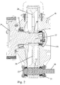
- the embodiment of the invention shown in Figure 2 differs from the prior art final drive shown in Figure 1 in that the splined coupling 30' between the wheel shaft 12 and the bull gear 26 is spherical.
- the splines on the wheel shaft 12 are slightly curved to be convex outward.
- the splined section of the wheel shaft 12 instead of being cylindrical as in the prior art, is barrelled. While this tends to reduce the overlap area between the splines on the bull gear 26 and the splines on the wheel shaft 12, this reduction in contact area does not affect the life of the splined coupling 30'.
- the curvature of the splines does however permit the axis of the wheel shaft 12 to move out of alignment with the axis of the bull gear 26 without placing additional stress on the gear mesh 32.
- the straight splines 30 have the tendency to turn the axis of rotation of the bull gear 26 so that it ceases to be parallel to the axis of the input shaft 20. When this occurs, additional wear occurs at the meshing teeth 32.
- the ability of the axis of the wheel shaft 12 to turn relative to the axis of the bull gear 26 results in the bull gear always rotating about an axis parallel to that of the input shaft 20.
Landscapes
- Life Sciences & Earth Sciences (AREA)
- Environmental Sciences (AREA)
- Gear Transmission (AREA)
- Transplanting Machines (AREA)
Abstract
Description
- The present invention relates to a final drive and is particularly applicable to a final drive for an agricultural vehicle, such as a combine harvester.
- The final drive of a combine harvester is a gearbox that not only transmits driving torque to the wheels but also supports the weight of the harvester. A final drive capable of meeting these demands, is shown in
Figure 1 , this being a typical final drive in current production. Such a typical final drive is also described inUS 4,003,444 . - Such a final drive comprises a casing within which a wheel shaft is rotatably supported. An input shaft, which is likewise supported in the casing, drives the wheel shaft through teeth. The weight of the harvester applies a wheel load induced bending moment to the wheel shaft, causing its axis to move out of parallel alignment with the axis of the input shaft. Such misalignment accelerates the wear of the gearing which couples the two shafts for rotation with one another. This problem is rendered more difficult to resolve by the fact that the wheel load induced bending moment which causes this misalignment is not constant but is affected by such factors as the weight of the harvested crop in the grain tank, the type of tyre fitted to the wheel and the field conditions.
-
GB 351,648 - However,
GB 351,648 -
US-A-5,911,286 relates to halfshaft assemblies for transmitting torque to the wheels of a vehicle utilizing swing-axle type independent rear suspensions. Each wheel is allowed to travel independently of the other wheel through the use of a splined crown joint at the wheel, a cardan joint at the transmission output and an independent swing axle suspension including control arms. - Although this application describes the use of splined crown joints at the wheels, they are intended to permit relative angular motion between the axle shaft and drive sleeve and allow the wheel to jounce and rebound. They are not intended to reduce wear.
- Due to the laterally offset and the construction of the final drive of an agricultural vehicle, the wear to the meshing teeth of the final drive due to the wheel load induced bending moment will be located remote from where the actual misalignment occurs. The misalignment occurs between the teeth of the wheel shaft and the bull gear, while the meshing teeth between the bull gear and the input shaft are subjected to increased wear. Implementing the solution as proposed in
GB 351,648 US-A-5,911,286 and providing curved teeth to the coupling were the actual wear is, thus between the meshing teeth of the bull gear and the input shaft, is not feasible since only two or three teeth mesh and transfer the necessary drive from the input shaft to the bull gear. When these teeth would be replaced by teeth sufficiently curved to take up the misalignment of the bull gear, the contact surface between the meshing teeth would be too small to adequately transfer the drive to the bull gear. - The present invention seeks therefore to provide a final drive suitable for an agricultural vehicle which is less prone to wear through gear misalignment, where the wear occurs at a different location then the misalignment of the gears.
- According to the present invention, there is provided a final drive for an agricultural vehicle having a casing, a wheel shaft supported in the casing by means of two support bearings spaced from one another along the length of the wheel shaft, an input shaft rotatably supported in the casing with its axis parallel to but laterally offset from that of the wheel shaft, and a bull gear connected to the wheel shaft by means of a splined coupling disposed between the support bearings of the wheel shaft and having external teeth meshing with teeth on the input shaft to transmit torque to the wheel shaft from the input shaft, characterised in that the splined coupling between the bull gear and the wheel shaft is spherical.
- It is usual to refer to a curved splined coupling as being "spherical" but this term should not be understood in a literal sense, in other words the splines do not need to have a common centre of curvature. The splines need only to be curved or crowned in the axial plane of the wheel shaft, to allow the wheel shaft to rotate about an axis that is not parallel to the rotational axis of the bull gear without increasing the stress on the teeth. In this way, the wheel shaft can rotate about an axis due to the wheel load induced bending moment, while no force is applied to cause the axis of rotation of the bull gear to move out of alignment with that of the input shaft. The teeth on the bull gear coupling it for rotation with the input shaft are thus not subjected to increased wear.
- Preferably, the splines on the wheel shaft are convex away from the axis of rotation of the wheel shaft, that is to say the splined region of the wheel shaft in engagement with the splines of the bull gear is barrelled instead of being cylindrical.
- It is alternatively, or additionally, possible for the inner splines on the bull gear to be convex towards the axis of rotation of the wheel shaft.
- The invention will now be described further, by way of example, with reference to the accompanying drawings, in which:
-
Figure 1 is a section of a prior art final drive, and -
Figure 2 is a section similar to that ofFigure 1 showing a final drive of the present invention. - The final drive in
Figure 1 comprises acasing 10 within which awheel shaft 12 connected to awheel flange 14 is rotatably supported by means of a pair ofconical roller bearings input shaft 20, which is likewise supported in thecasing 10 by means of a pair ofconical roller bearings wheel shaft 12 through teeth which mesh withteeth 32 on abull gear 26. Thebull gear 26 could in principle be formed integrally with thewheel shaft 12 but, as this would be difficult to manufacture, it is instead formed separately and coupled for rotation with thewheel shaft 12 by means ofstraight splines 30. - The weight of the harvester acting on the
wheel flange 14 applies a wheel load induced bending moment to thewheel shaft 12 tending to turn it in the direction of thearrow 34, causing its axis to move out of parallel alignment with the axis of theinput shaft 20. Such misalignment accelerates the wear of the gearing which couples the twoshafts teeth 32 coupling thebull gear 26 for rotation with theinput shaft 20. - The final drive of the invention shown in
Figure 2 is generally similar to that ofFigure 1 and, to avoid unnecessary repetition, components which are the same as those previously described have been allocated the same reference numerals and will not the described again. - The embodiment of the invention shown in
Figure 2 differs from the prior art final drive shown inFigure 1 in that the splined coupling 30' between thewheel shaft 12 and thebull gear 26 is spherical. The splines on thewheel shaft 12 are slightly curved to be convex outward. As a result, the splined section of thewheel shaft 12, instead of being cylindrical as in the prior art, is barrelled. While this tends to reduce the overlap area between the splines on thebull gear 26 and the splines on thewheel shaft 12, this reduction in contact area does not affect the life of the splined coupling 30'. The curvature of the splines does however permit the axis of thewheel shaft 12 to move out of alignment with the axis of thebull gear 26 without placing additional stress on thegear mesh 32. - In the case of the prior art final drive in
Figure 1 , thestraight splines 30 have the tendency to turn the axis of rotation of thebull gear 26 so that it ceases to be parallel to the axis of theinput shaft 20. When this occurs, additional wear occurs at themeshing teeth 32. In the present invention, the ability of the axis of thewheel shaft 12 to turn relative to the axis of thebull gear 26 results in the bull gear always rotating about an axis parallel to that of theinput shaft 20. - Instead of, or in addition to, providing the
wheel shaft 12 with outwards convex splines, it is possible to form the inner splines on thebull gear 26 to that they are convex towards the axis of rotation of the wheel shaft. It is not important which of the two sets of splines in made convex, as long as the axis of the wheel shaft can move out of alignment with that of thebull gear 26. - It can thus be seen from the foregoing description that by a simple modification the invention allows the life of a final drive to be increased without otherwise affecting its performance.
Claims (3)
- A final drive for an agricultural vehicle having a casing (10), a wheel shaft (12) supported in the casing by means of two support bearings (16,18) spaced from one another along the length of the wheel shaft (12), an input shaft (20) rotatably supported in the casing (10) with its axis parallel to but laterally offset from that of the wheel shaft (12), and a bull gear (26) connected to the wheel shaft (12) by means of a splined coupling (30) disposed between the support bearings (16,18) of the wheel shaft and having external teeth (32) meshing with teeth on the input shaft (20) to transmit torque to the wheel shaft (12) from the input shaft (20), characterised in that the splined coupling between the bull gear (26) and the wheel shaft (12) is spherical.
- A final drive as claimed in claim 1, wherein the splines (30') on the wheel shaft (12) are convex away from the axis of rotation of the wheel shaft (12).
- A final drive as claimed in claim 1 or 2, wherein the inner splines on the bull gear (26) are convex towards the axis of rotation of the wheel shaft (12).
Applications Claiming Priority (1)
| Application Number | Priority Date | Filing Date | Title |
|---|---|---|---|
| GB0512079A GB2427254A (en) | 2005-06-15 | 2005-06-15 | Final drive for an agricultural vehicle |
Publications (2)
| Publication Number | Publication Date |
|---|---|
| EP1733608A1 EP1733608A1 (en) | 2006-12-20 |
| EP1733608B1 true EP1733608B1 (en) | 2008-03-05 |
Family
ID=34855502
Family Applications (1)
| Application Number | Title | Priority Date | Filing Date |
|---|---|---|---|
| EP06115132A Active EP1733608B1 (en) | 2005-06-15 | 2006-06-08 | Final drive for an agricultural vehicle |
Country Status (5)
| Country | Link |
|---|---|
| US (1) | US20060283277A1 (en) |
| EP (1) | EP1733608B1 (en) |
| AT (1) | ATE387847T1 (en) |
| DE (1) | DE602006000623T2 (en) |
| GB (1) | GB2427254A (en) |
Families Citing this family (3)
| Publication number | Priority date | Publication date | Assignee | Title |
|---|---|---|---|---|
| CN103548497B (en) * | 2013-11-14 | 2015-07-22 | 江苏沃得农业机械有限公司 | Wheel type combine harvester rear axle power input connecting device |
| CN105889470A (en) * | 2016-06-07 | 2016-08-24 | 山东常林农业装备股份有限公司 | Transmission case assembly used for harvester and directly connected to drive axle |
| CN111075888A (en) * | 2019-12-31 | 2020-04-28 | 江阴市得灵机械有限公司 | High-torsion same-direction flat double structure |
Family Cites Families (11)
| Publication number | Priority date | Publication date | Assignee | Title |
|---|---|---|---|---|
| US76819A (en) * | 1868-04-14 | Improvement in shaft-coupling | ||
| GB351648A (en) * | 1929-12-09 | 1931-07-02 | Zahnradfabrik Ag | Improvements in or relating to power transmission gearing in motor vehicles |
| US2659585A (en) * | 1951-06-29 | 1953-11-17 | Goodman Mfg Co | Power drive connection for combined rotatable and oscillatable mining tools |
| US3192790A (en) * | 1962-01-29 | 1965-07-06 | Carrier Corp | Transmission gearing |
| GB1102871A (en) * | 1964-03-16 | 1968-02-14 | Budzich Tadeusz | Improvements in or relating to variable displacement hydraulic pumps |
| US4003444A (en) * | 1975-03-04 | 1977-01-18 | Kuboto Tekko Co., Ltd. | Construction for uniting the brake case cover, rear wheel axle case and terminal speed reduction unit case of tractor |
| US4453830A (en) * | 1980-03-27 | 1984-06-12 | Cooper Industries, Inc. | Output coupling for concrete mixer transmission |
| JPS5835406U (en) * | 1981-09-02 | 1983-03-08 | 株式会社クボタ | tractor axle case |
| US5911286A (en) * | 1997-06-12 | 1999-06-15 | Gkn Automotive Inc | Independent suspension and halfshaft assembly with double crown spline joint |
| JP2003106339A (en) * | 2001-09-28 | 2003-04-09 | Jatco Ltd | Joint structure of spline in automatic speed change gear |
| US6869366B2 (en) * | 2002-12-19 | 2005-03-22 | Easco Hand Tools Inc. | Universal joint |
-
2005
- 2005-06-15 GB GB0512079A patent/GB2427254A/en not_active Withdrawn
-
2006
- 2006-05-26 US US11/441,933 patent/US20060283277A1/en not_active Abandoned
- 2006-06-08 EP EP06115132A patent/EP1733608B1/en active Active
- 2006-06-08 AT AT06115132T patent/ATE387847T1/en not_active IP Right Cessation
- 2006-06-08 DE DE602006000623T patent/DE602006000623T2/en active Active
Also Published As
| Publication number | Publication date |
|---|---|
| DE602006000623D1 (en) | 2008-04-17 |
| DE602006000623T2 (en) | 2008-06-19 |
| ATE387847T1 (en) | 2008-03-15 |
| GB0512079D0 (en) | 2005-07-20 |
| GB2427254A (en) | 2006-12-20 |
| EP1733608A1 (en) | 2006-12-20 |
| US20060283277A1 (en) | 2006-12-21 |
Similar Documents
| Publication | Publication Date | Title |
|---|---|---|
| US6863634B2 (en) | Tandem axle power divider assembly with inboard slip driveshaft connection | |
| US7507161B2 (en) | Propshaft with constant velocity joint attachment | |
| EP3453555B1 (en) | Axle assembly having a drive pinion assembly | |
| US4289213A (en) | Angular output transfer case | |
| CN114502410A (en) | Bearing support for parallel motorized axle gear assembly | |
| USRE39323E1 (en) | Inter-axle differential assembly for a tandem drive axle set | |
| US6855087B2 (en) | Axle assembly | |
| JP6361604B2 (en) | Vehicle transfer structure | |
| JP2000025474A (en) | Steering driving shaft | |
| EP1733608B1 (en) | Final drive for an agricultural vehicle | |
| CN105793590A (en) | Vehicle transfer case with variable angle universal joint | |
| US20070267245A1 (en) | Floating Torque Tube Propeller Shaft Assembly | |
| JP2004155414A (en) | Inter-axle differential assembly for tandem driving axle set | |
| JP2009511839A (en) | Direct torque flow connection with optimum ratio in mounting method | |
| US6845690B2 (en) | Transmission system and method of making same | |
| CN220298225U (en) | Novel tractor front axle power transmission system | |
| US6957710B2 (en) | Tandem drive axle assembly | |
| CN105980249A (en) | Drive system for aircraft landing gear | |
| US20120015775A1 (en) | Differential assembly for a vehicle | |
| RU2674966C1 (en) | Mechanism of compensation for longitudinal displacements of the leading bridge | |
| KR102219950B1 (en) | Transfer case | |
| CN117048240A (en) | A new type of tractor front axle power transmission system | |
| CN117124774A (en) | All-terrain vehicle constant velocity half shaft | |
| JP2004352171A (en) | Power transmission device | |
| CN114466760A (en) | Wheel drive shaft device |
Legal Events
| Date | Code | Title | Description |
|---|---|---|---|
| PUAI | Public reference made under article 153(3) epc to a published international application that has entered the european phase |
Free format text: ORIGINAL CODE: 0009012 |
|
| AK | Designated contracting states |
Kind code of ref document: A1 Designated state(s): AT BE BG CH CY CZ DE DK EE ES FI FR GB GR HU IE IS IT LI LT LU LV MC NL PL PT RO SE SI SK TR |
|
| AX | Request for extension of the european patent |
Extension state: AL BA HR MK YU |
|
| 17P | Request for examination filed |
Effective date: 20070320 |
|
| 17Q | First examination report despatched |
Effective date: 20070420 |
|
| AKX | Designation fees paid |
Designated state(s): AT BE BG CH CY CZ DE DK EE ES FI FR GB GR HU IE IS IT LI LT LU LV MC NL PL PT RO SE SI SK TR |
|
| GRAP | Despatch of communication of intention to grant a patent |
Free format text: ORIGINAL CODE: EPIDOSNIGR1 |
|
| GRAS | Grant fee paid |
Free format text: ORIGINAL CODE: EPIDOSNIGR3 |
|
| GRAA | (expected) grant |
Free format text: ORIGINAL CODE: 0009210 |
|
| AK | Designated contracting states |
Kind code of ref document: B1 Designated state(s): AT BE BG CH CY CZ DE DK EE ES FI FR GB GR HU IE IS IT LI LT LU LV MC NL PL PT RO SE SI SK TR |
|
| REG | Reference to a national code |
Ref country code: GB Ref legal event code: FG4D |
|
| REG | Reference to a national code |
Ref country code: CH Ref legal event code: EP |
|
| REG | Reference to a national code |
Ref country code: IE Ref legal event code: FG4D |
|
| REF | Corresponds to: |
Ref document number: 602006000623 Country of ref document: DE Date of ref document: 20080417 Kind code of ref document: P |
|
| PG25 | Lapsed in a contracting state [announced via postgrant information from national office to epo] |
Ref country code: FI Free format text: LAPSE BECAUSE OF FAILURE TO SUBMIT A TRANSLATION OF THE DESCRIPTION OR TO PAY THE FEE WITHIN THE PRESCRIBED TIME-LIMIT Effective date: 20080305 Ref country code: ES Free format text: LAPSE BECAUSE OF FAILURE TO SUBMIT A TRANSLATION OF THE DESCRIPTION OR TO PAY THE FEE WITHIN THE PRESCRIBED TIME-LIMIT Effective date: 20080616 |
|
| PG25 | Lapsed in a contracting state [announced via postgrant information from national office to epo] |
Ref country code: AT Free format text: LAPSE BECAUSE OF FAILURE TO SUBMIT A TRANSLATION OF THE DESCRIPTION OR TO PAY THE FEE WITHIN THE PRESCRIBED TIME-LIMIT Effective date: 20080305 |
|
| NLV1 | Nl: lapsed or annulled due to failure to fulfill the requirements of art. 29p and 29m of the patents act | ||
| ET | Fr: translation filed | ||
| PG25 | Lapsed in a contracting state [announced via postgrant information from national office to epo] |
Ref country code: SI Free format text: LAPSE BECAUSE OF FAILURE TO SUBMIT A TRANSLATION OF THE DESCRIPTION OR TO PAY THE FEE WITHIN THE PRESCRIBED TIME-LIMIT Effective date: 20080305 Ref country code: PL Free format text: LAPSE BECAUSE OF FAILURE TO SUBMIT A TRANSLATION OF THE DESCRIPTION OR TO PAY THE FEE WITHIN THE PRESCRIBED TIME-LIMIT Effective date: 20080305 Ref country code: LV Free format text: LAPSE BECAUSE OF FAILURE TO SUBMIT A TRANSLATION OF THE DESCRIPTION OR TO PAY THE FEE WITHIN THE PRESCRIBED TIME-LIMIT Effective date: 20080305 |
|
| PG25 | Lapsed in a contracting state [announced via postgrant information from national office to epo] |
Ref country code: SK Free format text: LAPSE BECAUSE OF FAILURE TO SUBMIT A TRANSLATION OF THE DESCRIPTION OR TO PAY THE FEE WITHIN THE PRESCRIBED TIME-LIMIT Effective date: 20080305 Ref country code: NL Free format text: LAPSE BECAUSE OF FAILURE TO SUBMIT A TRANSLATION OF THE DESCRIPTION OR TO PAY THE FEE WITHIN THE PRESCRIBED TIME-LIMIT Effective date: 20080305 Ref country code: SE Free format text: LAPSE BECAUSE OF FAILURE TO SUBMIT A TRANSLATION OF THE DESCRIPTION OR TO PAY THE FEE WITHIN THE PRESCRIBED TIME-LIMIT Effective date: 20080605 Ref country code: CZ Free format text: LAPSE BECAUSE OF FAILURE TO SUBMIT A TRANSLATION OF THE DESCRIPTION OR TO PAY THE FEE WITHIN THE PRESCRIBED TIME-LIMIT Effective date: 20080305 Ref country code: PT Free format text: LAPSE BECAUSE OF FAILURE TO SUBMIT A TRANSLATION OF THE DESCRIPTION OR TO PAY THE FEE WITHIN THE PRESCRIBED TIME-LIMIT Effective date: 20080805 |
|
| PG25 | Lapsed in a contracting state [announced via postgrant information from national office to epo] |
Ref country code: RO Free format text: LAPSE BECAUSE OF FAILURE TO SUBMIT A TRANSLATION OF THE DESCRIPTION OR TO PAY THE FEE WITHIN THE PRESCRIBED TIME-LIMIT Effective date: 20080305 |
|
| PG25 | Lapsed in a contracting state [announced via postgrant information from national office to epo] |
Ref country code: IS Free format text: LAPSE BECAUSE OF FAILURE TO SUBMIT A TRANSLATION OF THE DESCRIPTION OR TO PAY THE FEE WITHIN THE PRESCRIBED TIME-LIMIT Effective date: 20080705 |
|
| PLBE | No opposition filed within time limit |
Free format text: ORIGINAL CODE: 0009261 |
|
| STAA | Information on the status of an ep patent application or granted ep patent |
Free format text: STATUS: NO OPPOSITION FILED WITHIN TIME LIMIT |
|
| PG25 | Lapsed in a contracting state [announced via postgrant information from national office to epo] |
Ref country code: LT Free format text: LAPSE BECAUSE OF FAILURE TO SUBMIT A TRANSLATION OF THE DESCRIPTION OR TO PAY THE FEE WITHIN THE PRESCRIBED TIME-LIMIT Effective date: 20080305 Ref country code: MC Free format text: LAPSE BECAUSE OF NON-PAYMENT OF DUE FEES Effective date: 20080630 Ref country code: DK Free format text: LAPSE BECAUSE OF FAILURE TO SUBMIT A TRANSLATION OF THE DESCRIPTION OR TO PAY THE FEE WITHIN THE PRESCRIBED TIME-LIMIT Effective date: 20080305 |
|
| 26N | No opposition filed |
Effective date: 20081208 |
|
| PG25 | Lapsed in a contracting state [announced via postgrant information from national office to epo] |
Ref country code: IE Free format text: LAPSE BECAUSE OF NON-PAYMENT OF DUE FEES Effective date: 20080609 Ref country code: EE Free format text: LAPSE BECAUSE OF FAILURE TO SUBMIT A TRANSLATION OF THE DESCRIPTION OR TO PAY THE FEE WITHIN THE PRESCRIBED TIME-LIMIT Effective date: 20080305 Ref country code: BG Free format text: LAPSE BECAUSE OF FAILURE TO SUBMIT A TRANSLATION OF THE DESCRIPTION OR TO PAY THE FEE WITHIN THE PRESCRIBED TIME-LIMIT Effective date: 20080605 |
|
| PG25 | Lapsed in a contracting state [announced via postgrant information from national office to epo] |
Ref country code: CY Free format text: LAPSE BECAUSE OF FAILURE TO SUBMIT A TRANSLATION OF THE DESCRIPTION OR TO PAY THE FEE WITHIN THE PRESCRIBED TIME-LIMIT Effective date: 20080305 |
|
| PG25 | Lapsed in a contracting state [announced via postgrant information from national office to epo] |
Ref country code: HU Free format text: LAPSE BECAUSE OF FAILURE TO SUBMIT A TRANSLATION OF THE DESCRIPTION OR TO PAY THE FEE WITHIN THE PRESCRIBED TIME-LIMIT Effective date: 20080906 Ref country code: LU Free format text: LAPSE BECAUSE OF NON-PAYMENT OF DUE FEES Effective date: 20080608 |
|
| PG25 | Lapsed in a contracting state [announced via postgrant information from national office to epo] |
Ref country code: TR Free format text: LAPSE BECAUSE OF FAILURE TO SUBMIT A TRANSLATION OF THE DESCRIPTION OR TO PAY THE FEE WITHIN THE PRESCRIBED TIME-LIMIT Effective date: 20080305 |
|
| PG25 | Lapsed in a contracting state [announced via postgrant information from national office to epo] |
Ref country code: GR Free format text: LAPSE BECAUSE OF FAILURE TO SUBMIT A TRANSLATION OF THE DESCRIPTION OR TO PAY THE FEE WITHIN THE PRESCRIBED TIME-LIMIT Effective date: 20080606 |
|
| REG | Reference to a national code |
Ref country code: CH Ref legal event code: PL |
|
| PG25 | Lapsed in a contracting state [announced via postgrant information from national office to epo] |
Ref country code: CH Free format text: LAPSE BECAUSE OF NON-PAYMENT OF DUE FEES Effective date: 20080630 Ref country code: LI Free format text: LAPSE BECAUSE OF NON-PAYMENT OF DUE FEES Effective date: 20080630 |
|
| PG25 | Lapsed in a contracting state [announced via postgrant information from national office to epo] |
Ref country code: CH Free format text: LAPSE BECAUSE OF NON-PAYMENT OF DUE FEES Effective date: 20100630 Ref country code: LI Free format text: LAPSE BECAUSE OF NON-PAYMENT OF DUE FEES Effective date: 20100630 |
|
| REG | Reference to a national code |
Ref country code: DE Ref legal event code: R082 Ref document number: 602006000623 Country of ref document: DE Representative=s name: PATENTANWAELTE WALLACH, KOCH & PARTNER, DE |
|
| REG | Reference to a national code |
Ref country code: DE Ref legal event code: R082 Ref document number: 602006000623 Country of ref document: DE Representative=s name: PATENTANWAELTE WALLACH, KOCH & PARTNER, DE Effective date: 20140428 Ref country code: DE Ref legal event code: R081 Ref document number: 602006000623 Country of ref document: DE Owner name: CNH INDUSTRIAL BELGIUM NV, BE Free format text: FORMER OWNER: CNH BELGIUM NV, ZEDELGEM, BE Effective date: 20140428 Ref country code: DE Ref legal event code: R082 Ref document number: 602006000623 Country of ref document: DE Representative=s name: PATENTANWAELTE WALLACH, KOCH, DR. HAIBACH, FEL, DE Effective date: 20140428 |
|
| REG | Reference to a national code |
Ref country code: FR Ref legal event code: CD Owner name: CNH INDUSTRIAL BELGIUM NV Effective date: 20140725 |
|
| REG | Reference to a national code |
Ref country code: FR Ref legal event code: PLFP Year of fee payment: 11 |
|
| REG | Reference to a national code |
Ref country code: FR Ref legal event code: PLFP Year of fee payment: 12 |
|
| REG | Reference to a national code |
Ref country code: FR Ref legal event code: PLFP Year of fee payment: 13 |
|
| REG | Reference to a national code |
Ref country code: DE Ref legal event code: R082 Ref document number: 602006000623 Country of ref document: DE Representative=s name: MEISSNER BOLTE PATENTANWAELTE RECHTSANWAELTE P, DE |
|
| PGFP | Annual fee paid to national office [announced via postgrant information from national office to epo] |
Ref country code: GB Payment date: 20200620 Year of fee payment: 15 Ref country code: IT Payment date: 20200612 Year of fee payment: 15 |
|
| REG | Reference to a national code |
Ref country code: DE Ref legal event code: R084 Ref document number: 602006000623 Country of ref document: DE |
|
| REG | Reference to a national code |
Ref country code: BE Ref legal event code: MM Effective date: 20200630 |
|
| PG25 | Lapsed in a contracting state [announced via postgrant information from national office to epo] |
Ref country code: BE Free format text: LAPSE BECAUSE OF NON-PAYMENT OF DUE FEES Effective date: 20200630 |
|
| GBPC | Gb: european patent ceased through non-payment of renewal fee |
Effective date: 20210608 |
|
| PG25 | Lapsed in a contracting state [announced via postgrant information from national office to epo] |
Ref country code: GB Free format text: LAPSE BECAUSE OF NON-PAYMENT OF DUE FEES Effective date: 20210608 |
|
| PG25 | Lapsed in a contracting state [announced via postgrant information from national office to epo] |
Ref country code: IT Free format text: LAPSE BECAUSE OF NON-PAYMENT OF DUE FEES Effective date: 20210608 |
|
| PGFP | Annual fee paid to national office [announced via postgrant information from national office to epo] |
Ref country code: DE Payment date: 20250626 Year of fee payment: 20 |
|
| PGFP | Annual fee paid to national office [announced via postgrant information from national office to epo] |
Ref country code: FR Payment date: 20250624 Year of fee payment: 20 |