EP1732706B1 - An improved roller for selectively applying paint at surface corners - Google Patents
An improved roller for selectively applying paint at surface corners Download PDFInfo
- Publication number
- EP1732706B1 EP1732706B1 EP05722336A EP05722336A EP1732706B1 EP 1732706 B1 EP1732706 B1 EP 1732706B1 EP 05722336 A EP05722336 A EP 05722336A EP 05722336 A EP05722336 A EP 05722336A EP 1732706 B1 EP1732706 B1 EP 1732706B1
- Authority
- EP
- European Patent Office
- Prior art keywords
- paint
- paint roller
- roller
- resilient means
- rolling guide
- Prior art date
- Legal status (The legal status is an assumption and is not a legal conclusion. Google has not performed a legal analysis and makes no representation as to the accuracy of the status listed.)
- Not-in-force
Links
- 239000003973 paint Substances 0.000 title claims abstract description 100
- 238000005096 rolling process Methods 0.000 claims abstract description 22
- 238000000034 method Methods 0.000 claims description 7
- 239000013536 elastomeric material Substances 0.000 claims 1
- 230000004888 barrier function Effects 0.000 description 8
- 238000010422 painting Methods 0.000 description 6
- 230000008901 benefit Effects 0.000 description 4
- 239000000463 material Substances 0.000 description 4
- 239000012466 permeate Substances 0.000 description 3
- 238000002360 preparation method Methods 0.000 description 3
- 230000000295 complement effect Effects 0.000 description 2
- 230000006835 compression Effects 0.000 description 2
- 238000007906 compression Methods 0.000 description 2
- 238000005299 abrasion Methods 0.000 description 1
- 230000009471 action Effects 0.000 description 1
- 238000004140 cleaning Methods 0.000 description 1
- 238000007796 conventional method Methods 0.000 description 1
- 238000007598 dipping method Methods 0.000 description 1
- 229920001971 elastomer Polymers 0.000 description 1
- 239000000806 elastomer Substances 0.000 description 1
- 239000012530 fluid Substances 0.000 description 1
- 238000001746 injection moulding Methods 0.000 description 1
- 230000002452 interceptive effect Effects 0.000 description 1
- 230000000873 masking effect Effects 0.000 description 1
- 238000012986 modification Methods 0.000 description 1
- 230000004048 modification Effects 0.000 description 1
Images


Classifications
-
- B—PERFORMING OPERATIONS; TRANSPORTING
- B05—SPRAYING OR ATOMISING IN GENERAL; APPLYING FLUENT MATERIALS TO SURFACES, IN GENERAL
- B05C—APPARATUS FOR APPLYING FLUENT MATERIALS TO SURFACES, IN GENERAL
- B05C17/00—Hand tools or apparatus using hand held tools, for applying liquids or other fluent materials to, for spreading applied liquids or other fluent materials on, or for partially removing applied liquids or other fluent materials from, surfaces
- B05C17/02—Rollers ; Hand tools comprising coating rollers or coating endless belts
- B05C17/0212—Rollers ; Hand tools comprising coating rollers or coating endless belts the coating surface of the roller being a body of revolution generated by a generatrix that is not a straight line parallel to the roller axis, e.g. for allowing coating of non planar surfaces
-
- B—PERFORMING OPERATIONS; TRANSPORTING
- B05—SPRAYING OR ATOMISING IN GENERAL; APPLYING FLUENT MATERIALS TO SURFACES, IN GENERAL
- B05C—APPARATUS FOR APPLYING FLUENT MATERIALS TO SURFACES, IN GENERAL
- B05C17/00—Hand tools or apparatus using hand held tools, for applying liquids or other fluent materials to, for spreading applied liquids or other fluent materials on, or for partially removing applied liquids or other fluent materials from, surfaces
- B05C17/02—Rollers ; Hand tools comprising coating rollers or coating endless belts
- B05C17/03—Rollers ; Hand tools comprising coating rollers or coating endless belts with feed system for supplying material from an external source or with a reservoir or container for liquid or other fluent material located in or on the hand tool outside the coating roller
- B05C17/0308—Rollers ; Hand tools comprising coating rollers or coating endless belts with feed system for supplying material from an external source or with a reservoir or container for liquid or other fluent material located in or on the hand tool outside the coating roller the liquid being supplied to the inside of the coating roller
Definitions
- the present invention relates to apparatuses for applying fluids such as, paint, onto surfaces.
- the present invention relates to a paint roller for selectively applying paint at surface corners.
- Paint rollers for applying paint onto surfaces are known.
- paint rollers typically have paint-absorbing surfaces that are dipped into paint containers and then rolled over surfaces that are to be painted.
- Another type of paint rollers has a permeable surface through which paint, stored inside such paint rollers, can flow through for application onto surfaces that are to be painted.
- paint rollers works well for a flat, even surface on which only a single paint shade or color is to be applied.
- a problem arises when such paint rollers are used to apply paint at surface corners formed, for example, by two walls or between a wall and a ceiling. This is a problem because paint desired on one surface may be undesirably applied onto an adjacent surface.
- Prior art paint rollers that alleviate the above problem include US Patent 5,623,740, issued to Burns et al. , in which an apparatus provides a shield that acts as a barrier to paint being applied onto an adjacent surface.
- Such prior art paint rollers provide shield-like barriers that are detachably mounted to the paint rollers.
- the shield-like barriers causes other problems.
- the barrier may be required to contact an adjacent surface for alignment purposes and presents a problem when an adjacent surface has wet paint or is delicate. Consequently, the adjacent surface can be damaged or abrasion by contact with the guard.
- shield-like barriers or guards are accessories that typically require assembling or attaching, which adds complexity to prior art paint rollers.
- Document DE-U-1775952 shows the features of the preamble of claim 1.
- Another problem is that an uneven or rough painting surface will cause the users of prior art paint rollers to skip certain areas of the surface, given the inherent rigidity of the paint rollers.
- the present invention superficially resembles an earlier publication, WO-A-03/082479 ( PCT/SG03/00015 ) by the same inventor, Mr Poh Leong Er.
- a means to minimize excessive application of force when using the paint roller will also be desirable.
- the present invention seeks to provide an apparatus and method for applying paint to surfaces and surface corners.
- the present invention provides a paint roller for applying paint onto a surface comprising the features of claim 1.
- the present invention provides a method of selectively applying paint onto surfaces and surface corners, the method comprising the steps according to claim 12.
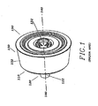
- FIG. 1 is an earlier invention by the same inventor for painting surface corners, exemplifying prior art inventions
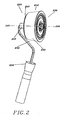
- FIG. 2 is an elevational view of one embodiment of the present invention showing the main elements
- FIG. 3 shows how the integral guard prevents excessive force from being applied
- FIG. 4 is an exploded view of one embodiment of the present invention.
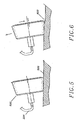
- FIG. 5 is a lateral view showing how the present invention is able to accommodate even surfaces, while FIG. 6 shows how the present invention is able to accommodate uneven surfaces;
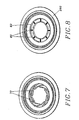
- FIG. 7 and FIG. 8 show variations of the resilient means that can be used.
- One advantage of the preferred embodiment is that paint may be applied to surface corners with precision, without damage to the surface as a barrier or shield is not needed.
- Another advantage is that an embodiment of the present invention allows paint to be applied to uneven or rough surfaces.
- Yet another advantage is that excessive force when applying paint is reduced, so that thin, even coats of paint may be applied to a surface.
- a paint roller of the prior art adapted for painting surface corners generally comprises a frustoconically-shaped applicator 110 with two opposite ends, 120, 130. One of these ends has a coupler 122 while the other end 130 has a planar cross-section smaller planar cross-section of the end 120 with the coupler 122.
- the coupler end 120 is disposed centrally relative to the planar cross-sections of both ends 120, 130 and permits the applicator to rotate about an axis 140.
- An external surface 150 joins the two ends and a paint-absorbable member 152 is mounted to the external surface of the applicator. Paint may be introduced via a closable inlet 132 into a chamber formed by the external surface 152 and the two ends 120, 130. The paint then permeates the perforations (not shown) in the external surface to the paint-absorbable member 152.
- these embodiments may simply be dipped into a container of paint to charge the paint-absorbable member.
- paint rollers as the applicator is rotated or rolled onto the surface, paint is deposited onto the surface.
- paint rollers of the prior art may permit excessive paint to be applied while they may not apply paint precisely at surface corners, or are able to handle uneven or rough surfaces well.
- the features of embodiments of the present invention can overcome, or at least alleviate these problems ( FIG. 2 ).
- the following elements of the embodiment of the present invention are similar to the prior art.
- the present embodiment of the invention is a paint roller comprising a frustoconically-shaped applicator 210 with two opposite ends: a coupler end 220, and a distal end 230.
- the coupler end has a coupler 222 that fits a handle 224 while the distal end 230 has a planar cross-section substantially different (that is, either smaller or larger than) than that of the planar cross-section of the coupler end 220.
- the coupler 222 is disposed centrally relative to the planar cross-sections of both ends 220, 230 and permits the applicator to rotate about an axis 240.
- An external surface 250 joins the two ends and a paint-absorbable member 252 is mounted to the external surface of the applicator.
- the present embodiment of the invention described thus far resembles paint rollers of the prior art.
- the planar cross-section of the distal end 230 is larger than the planar cross-section of the coupler end 220 to form the frustoconically-shaped applicator. It will be appreciated that a paint applicator possessing the elements of present invention but with the planar cross-section of the distal end smaller than that of the coupler end will also come within the scope of the present invention.
- a circular integral guard 260 is disposed at the coupler end 220 of the applicator.
- this circular integral guard is carefully pre-determined such that the paint-absorbable member is not unduly compressed during application of the paint.
- FIG. 3 the longitudinal cross-sectional views of the invention shows how the integral guard 260 can limit the compression of the paint-absorbable member 252. Under correct use, a normal application force will not cause the integral guard 260 to contact the surface to be painted ( FIG. 3A ). Should an excessive force be applied by the user, the edge of integral guard will come into contact with the surface being painted 300 ( FIG. 3B ) and prevent the paint absorbable member 252 from being overly compressed.
- the paint-absorbable member may be over-compressed, allowing an undesirable amount of paint to be deposited.
- the diameter of the integral guard has to be carefully pre-determined through experimentation: it has to be sufficiently large to prevent excessive compression of the paint-absorbable surface while not so large as to interfere with the painting of the surface. Factors such as the size of the applicator, and the thickness and type of paint absorbable member used have to be taken into consideration.
- the applicator of the present invention is able to move eccentrically about the axis 240. This bit of eccentric rotation allows the applicator to accommodate uneven or rough surfaces.
- the eccentric rotation of the applicator is achieved by a set of elements, best seen in the exploded view of the first embodiment of the present invention incorporating a chamber 270 or reservoir to contain paint ( FIG. 4 ).
- the chamber is accessible by means of a closable inlet 232, of a fixed diameter, in the distal end 232.
- a rolling guide 280 with a central orifice 282 of diameter larger than the inlet diameter is disposed coaxially over the distal end 230 of the applicator.
- a resilient means 290 is radially disposed about the center of the rolling guide 280.
- the resilient guide is made of a suitable material such as elastomer, and is shaped like a washer-like perforated disk as shown in FIG. 4 .
- the circumference of the resilient means coacts with the rolling guide as the resilient means contacts the circular wall 284 that forms the central orifice 282 of the rolling guide 280.
- the resilient means 290 is held in place by the flange 292 of a detachable retainer 294 that secures to the distal end 230. This securing is possible as the detachable retainer 294 has engagement lugs 296 that engage complementary lugs 234 in the internal walls of the inlet 230.
- the wall 298 of the internal diameter of the resilient means 290 contacts the external wall of the retainer 292 without interfering with the action of the engagement lugs 296.
- paint is introduced into the reservoir 270 through the closable inlet 232 and the retainer 292.
- the inlet is then closed with a cap 299 that reversibly engages the retainer 292 such that a liquid-tight seal is achieved.
- the paint then flows through perforations 272 in the external surface to permeate the paint-absorbable member (not shown for clarity).
- paint may be applied to a substantially even surface 500 by the user in the usual manner by holding the handle (not shown) connected to the shaft 224 which is in turn connected to the coupler end 220 ( FIG. 5 ).
- the paint-absorbable member and the rolling guide come into contact with the surface to be painted.
- the roller encounters uneven or rough patches 600 on the surface ( FIG. 6 )
- it is able to automatically accommodate such patches by being able to rotate eccentrically relative to the rolling guide to compensate for the uneven surface 600.
- the arrow heads in FIG. 6 indicate the movements of these rolling guide and corner roller and the axis lines show that the axis of the rolling guide and the axis of the corner roller not coinciding when the roller is accommodating the uneven surface.
- the integral guard 260 at the coupler end 220 does not come into contact with the surface being painted. As the integral guard 260 does not contact the surface under normal usage, it functions differently from the shields or barriers of paint rollers of the prior art. However, a novice user may apply excessive force when using the paint roller. When this happens, the integral guard 260 contacts the surface and prevents the paint-absorbable member from being excessively compressed ( FIG. 3 ).
- Another embodiment of the present invention does not provide a chamber or reservoir for paint (figure not shown) and the user must periodically charge the paint-absorbing member with paint by dipping the applicator into a container of paint, or by rolling it in paint held in a pan.
- the retainer is secured by simply engaging its lugs with complementary members in the distal end of the applicator.
- Other elements of the invention enabling the eccentric rolling of the rolling guide.
- the roller may then be used like any other corner roller of the prior art without a paint reservoir.
- FIGS. 7 & 8 While the preferred embodiment of the resilient means is that of a washer-like form made of elastomeric materials, other embodiments of the resilient means are possible ( FIGS. 7 & 8 ). These include a plurality of curved "fingers" 70 radiating from the wall of the central orifice of the rolling guide coacting against the retainer wall ( FIG. 7 ). Alternatively, instead of curved fingers, a plurality of coil springs 80 coacting on a flexible circular wall 82 may be used to surround the retainer.
- embodiments of the present invention may be made by injection-molding one or more suitable plastic materials. While the integral guide may be molded as one piece with the applicator, it is functionally-distinct from the coupler end.
- the method of using paint roller of the present invention therefor comprises removing the cap of the closable inlet, filling the reservoir with paint of the desired color, securely replacing the cap, and waiting a short while for the paint to permeate to the paint absorbable surface. Thereafter, the corner roller may then be rolled on the surface to lightly compress the paint absorbable surface to release paint in a thin, even coat, using the rolling guide as a guide as necessary.
- the present invention comprises according to some selected features, a frustoconically-shaped paint applicator with an integral guard for preventing excessive force from being exerted, and a rolling guide that allows uneven surfaces to be painted.
- the present invention also provides a method of using such a paint roller as defined in claim 12. Uneven surfaces may also be quickly painted without undue preparation.
- the present invention can overcome, or at least alleviate, the problems of the prior art.
Abstract
Description
- The present invention relates to apparatuses for applying fluids such as, paint, onto surfaces. In particular, the present invention relates to a paint roller for selectively applying paint at surface corners.
- Paint rollers for applying paint onto surfaces are known. Typically, such paint rollers have paint-absorbing surfaces that are dipped into paint containers and then rolled over surfaces that are to be painted. Another type of paint rollers has a permeable surface through which paint, stored inside such paint rollers, can flow through for application onto surfaces that are to be painted.
- Generally, existing paint rollers works well for a flat, even surface on which only a single paint shade or color is to be applied. However, a problem arises when such paint rollers are used to apply paint at surface corners formed, for example, by two walls or between a wall and a ceiling. This is a problem because paint desired on one surface may be undesirably applied onto an adjacent surface.
- Prior art paint rollers that alleviate the above problem include
US Patent 5,623,740, issued to Burns et al. , in which an apparatus provides a shield that acts as a barrier to paint being applied onto an adjacent surface. Such prior art paint rollers provide shield-like barriers that are detachably mounted to the paint rollers. However, use of the shield-like barriers causes other problems. For example, the barrier may be required to contact an adjacent surface for alignment purposes and presents a problem when an adjacent surface has wet paint or is delicate. Consequently, the adjacent surface can be damaged or abrasion by contact with the guard. Furthermore, shield-like barriers or guards are accessories that typically require assembling or attaching, which adds complexity to prior art paint rollers. DocumentDE-U-1775952 shows the features of the preamble of claim 1. - Another problem is that an uneven or rough painting surface will cause the users of prior art paint rollers to skip certain areas of the surface, given the inherent rigidity of the paint rollers.
- Yet another problem common to all paint rollers, is that application of an overly heavy force in use will contribute to excessive paint being squeezed out, resulting in an undesirably thick coat of paint.
- The present invention superficially resembles an earlier publication,
WO-A-03/082479 PCT/SG03/00015 - However, the earlier publication,
WO-A-03/082479 - Therefore, a need clearly exists for a novel paint roller for selectively applying paint at surface corners and that does not need separate accessories such as a barrier or a guard to be assembled or attached. In addition, a means to minimize excessive application of force when using the paint roller will also be desirable.
- The present invention seeks to provide an apparatus and method for applying paint to surfaces and surface corners.
- Accordingly, in one aspect, the present invention provides a paint roller for applying paint onto a surface comprising the features of claim 1.
- In another aspect, the present invention provides a method of selectively applying paint onto surfaces and surface corners, the method comprising the steps according to claim 12.
- A preferred embodiment of the present invention will now be more fully described, by way of example, with reference to the drawings of which:
-
FIG. 1 is an earlier invention by the same inventor for painting surface corners, exemplifying prior art inventions; -
FIG. 2 is an elevational view of one embodiment of the present invention showing the main elements; -
FIG. 3 shows how the integral guard prevents excessive force from being applied; -
FIG. 4 is an exploded view of one embodiment of the present invention. -
FIG. 5 is a lateral view showing how the present invention is able to accommodate even surfaces, whileFIG. 6 shows how the present invention is able to accommodate uneven surfaces; and -
FIG. 7 and FIG. 8 show variations of the resilient means that can be used. - A detailed description of the present invention will now be given in accordance with the preferred embodiments of the invention. In the following description, details are provided to describe the preferred embodiments. It shall be apparent to one skilled in the art, however, that the invention may be practiced without such details. Some of these details may not be described at length so as not to obscure the invention.
- There are many advantages of the preferred embodiment of the invention. One advantage of the preferred embodiment is that paint may be applied to surface corners with precision, without damage to the surface as a barrier or shield is not needed.
- Another advantage is that an embodiment of the present invention allows paint to be applied to uneven or rough surfaces.
- Yet another advantage is that excessive force when applying paint is reduced, so that thin, even coats of paint may be applied to a surface.
- Referring now to
FIG. 1 , it may be seen that a paint roller of the prior art adapted for painting surface corners generally comprises a frustoconically-shaped applicator 110 with two opposite ends, 120, 130. One of these ends has acoupler 122 while theother end 130 has a planar cross-section smaller planar cross-section of theend 120 with thecoupler 122. Thecoupler end 120 is disposed centrally relative to the planar cross-sections of bothends axis 140. - An
external surface 150 joins the two ends and a paint-absorbable member 152 is mounted to the external surface of the applicator. Paint may be introduced via aclosable inlet 132 into a chamber formed by theexternal surface 152 and the twoends absorbable member 152. - Alternatively, in other similar embodiments without a chamber or reservoir for the paint, these embodiments may simply be dipped into a container of paint to charge the paint-absorbable member. In all paint rollers, as the applicator is rotated or rolled onto the surface, paint is deposited onto the surface.
- However, as explained above, paint rollers of the prior art may permit excessive paint to be applied while they may not apply paint precisely at surface corners, or are able to handle uneven or rough surfaces well.
- The features of embodiments of the present invention can overcome, or at least alleviate these problems (
FIG. 2 ). The following elements of the embodiment of the present invention are similar to the prior art. The present embodiment of the invention is a paint roller comprising a frustoconically-shaped applicator 210 with two opposite ends: acoupler end 220, and adistal end 230. - The coupler end has a
coupler 222 that fits ahandle 224 while thedistal end 230 has a planar cross-section substantially different (that is, either smaller or larger than) than that of the planar cross-section of thecoupler end 220. Thecoupler 222 is disposed centrally relative to the planar cross-sections of bothends axis 240. - An
external surface 250 joins the two ends and a paint-absorbable member 252 is mounted to the external surface of the applicator. The present embodiment of the invention described thus far resembles paint rollers of the prior art. In the preferred embodiment of the present invention, the planar cross-section of thedistal end 230 is larger than the planar cross-section of thecoupler end 220 to form the frustoconically-shaped applicator. It will be appreciated that a paint applicator possessing the elements of present invention but with the planar cross-section of the distal end smaller than that of the coupler end will also come within the scope of the present invention. - To prevent excessive force from being applied and consequently squeezing out too much paint from the paint-
absorbable member 252, a circularintegral guard 260 is disposed at thecoupler end 220 of the applicator. - The diameter of this circular integral guard is carefully pre-determined such that the paint-absorbable member is not unduly compressed during application of the paint. In
FIG. 3 , the longitudinal cross-sectional views of the invention shows how theintegral guard 260 can limit the compression of the paint-absorbable member 252. Under correct use, a normal application force will not cause theintegral guard 260 to contact the surface to be painted (FIG. 3A ). Should an excessive force be applied by the user, the edge of integral guard will come into contact with the surface being painted 300 (FIG. 3B ) and prevent the paintabsorbable member 252 from being overly compressed. - In paint rollers of the prior art not possessing this novel element, the paint-absorbable member may be over-compressed, allowing an undesirable amount of paint to be deposited. The diameter of the integral guard has to be carefully pre-determined through experimentation: it has to be sufficiently large to prevent excessive compression of the paint-absorbable surface while not so large as to interfere with the painting of the surface. Factors such as the size of the applicator, and the thickness and type of paint absorbable member used have to be taken into consideration.
- To permit the applicator to accommodate uneven or rough surfaces, the applicator of the present invention is able to move eccentrically about the
axis 240. This bit of eccentric rotation allows the applicator to accommodate uneven or rough surfaces. - The eccentric rotation of the applicator is achieved by a set of elements, best seen in the exploded view of the first embodiment of the present invention incorporating a
chamber 270 or reservoir to contain paint (FIG. 4 ). - The chamber is accessible by means of a
closable inlet 232, of a fixed diameter, in thedistal end 232. A rollingguide 280 with acentral orifice 282 of diameter larger than the inlet diameter is disposed coaxially over thedistal end 230 of the applicator. Aresilient means 290 is radially disposed about the center of the rollingguide 280. In this preferred embodiment, the resilient guide is made of a suitable material such as elastomer, and is shaped like a washer-like perforated disk as shown inFIG. 4 . - The circumference of the resilient means coacts with the rolling guide as the resilient means contacts the
circular wall 284 that forms thecentral orifice 282 of the rollingguide 280. The resilient means 290 is held in place by theflange 292 of adetachable retainer 294 that secures to thedistal end 230. This securing is possible as thedetachable retainer 294 has engagement lugs 296 that engagecomplementary lugs 234 in the internal walls of theinlet 230. Thewall 298 of the internal diameter of the resilient means 290 contacts the external wall of theretainer 292 without interfering with the action of the engagement lugs 296. - To use this embodiment of the present invention, paint is introduced into the
reservoir 270 through theclosable inlet 232 and theretainer 292. The inlet is then closed with acap 299 that reversibly engages theretainer 292 such that a liquid-tight seal is achieved. The paint then flows throughperforations 272 in the external surface to permeate the paint-absorbable member (not shown for clarity). - A person skilled in the art will appreciate that the presence of the resilient means sandwiched between the rolling guide and the
retainer 292 allows the rolling guide to move eccentrically relative to the axis of the applicator, within a certain range of motion. - With an embodiment of the present invention, paint may be applied to a substantially even surface 500 by the user in the usual manner by holding the handle (not shown) connected to the
shaft 224 which is in turn connected to the coupler end 220 (FIG. 5 ). As the roller is rolled over the surface to be painted, the paint-absorbable member and the rolling guide come into contact with the surface to be painted. As the roller encounters uneven orrough patches 600 on the surface (FIG. 6 ), it is able to automatically accommodate such patches by being able to rotate eccentrically relative to the rolling guide to compensate for theuneven surface 600. The arrow heads inFIG. 6 indicate the movements of these rolling guide and corner roller and the axis lines show that the axis of the rolling guide and the axis of the corner roller not coinciding when the roller is accommodating the uneven surface. - Under normal use, the
integral guard 260 at thecoupler end 220 does not come into contact with the surface being painted. As theintegral guard 260 does not contact the surface under normal usage, it functions differently from the shields or barriers of paint rollers of the prior art. However, a novice user may apply excessive force when using the paint roller. When this happens, theintegral guard 260 contacts the surface and prevents the paint-absorbable member from being excessively compressed (FIG. 3 ). - Another embodiment of the present invention does not provide a chamber or reservoir for paint (figure not shown) and the user must periodically charge the paint-absorbing member with paint by dipping the applicator into a container of paint, or by rolling it in paint held in a pan.
- In that embodiment, there is no inlet and the retainer is secured by simply engaging its lugs with complementary members in the distal end of the applicator. Other elements of the invention enabling the eccentric rolling of the rolling guide. The roller may then be used like any other corner roller of the prior art without a paint reservoir.
- The person skilled in the art will appreciate that while only a few embodiments of the present invention have been described, it should be understood that these embodiments are only illustrative and do not limit the invention. Many variations are possible under the scope of the present invention. These include variations in handle shape, coupler function, means of detachably engaging the retainer, closable inlet, choice of material for the paint-absorbing member, and form of the resilient means.
- While the preferred embodiment of the resilient means is that of a washer-like form made of elastomeric materials, other embodiments of the resilient means are possible (
FIGS. 7 & 8 ). These include a plurality of curved "fingers" 70 radiating from the wall of the central orifice of the rolling guide coacting against the retainer wall (FIG. 7 ). Alternatively, instead of curved fingers, a plurality ofcoil springs 80 coacting on a flexiblecircular wall 82 may be used to surround the retainer. - A person skilled in the art will appreciate that embodiments of the present invention may be made by injection-molding one or more suitable plastic materials. While the integral guide may be molded as one piece with the applicator, it is functionally-distinct from the coupler end.
- With such an embodiment, painting of surface corners is made much easier. No preparation such as temporarily shielding the edge of the corner with masking tape to prevent the user from inadvertently painting over the edge is needed. Other conventional techniques to prepare the surface, such as cleaning or sanding it ay be done before applying the paint.
- The method of using paint roller of the present invention therefor comprises removing the cap of the closable inlet, filling the reservoir with paint of the desired color, securely replacing the cap, and waiting a short while for the paint to permeate to the paint absorbable surface. Thereafter, the corner roller may then be rolled on the surface to lightly compress the paint absorbable surface to release paint in a thin, even coat, using the rolling guide as a guide as necessary.
- Excessive force during use is prevented by the integral guard and uneven surfaces may be painted without any prior preparation if desired.
- The present invention comprises according to some selected features, a frustoconically-shaped paint applicator with an integral guard for preventing excessive force from being exerted, and a rolling guide that allows uneven surfaces to be painted.
- The present invention also provides a method of using such a paint roller as defined in claim 12. Uneven surfaces may also be quickly painted without undue preparation. The present invention can overcome, or at least alleviate, the problems of the prior art.
- It will be appreciated that although one preferred embodiment has been described in detail, various modifications and improvements can be made by a person skilled in the art without departing from the scope of the present invention.
Claims (12)
- - A paint roller (200) for applying paint onto a surface (300, 500, 600) comprising a frustoconically-shaped applicator (210) having:- a coupler end (220);- a distal end (230) opposite the coupler end (220);- an external surface (250) between the coupler end (220) and the distal end (230); and- a paint-absorbable member (252);
the paint roller (200) further comprising:- a circular integral guard (260) disposed at the coupler end (220);- a rolling guide (280) disposed at the distal end (230); characterized by- a resilient means (290) radially disposed about the center of the rolling guide (280) enabling the rolling guide (280) to move eccentrically about an axis (240) of the applicator. - The paint roller (200) of Claim 1, wherein
a planar cross-section of the coupler end (220) has a different size than the planar cross-section of the distal end (230). - The paint roller of Claim 1 or 2, wherein
the frustoconically-shaped applicator (210) further comprises a chamber (270) defined by the coupler end (220), the distal end (230) and the external surface (250) joining the coupler end (220) and the distal end (230); the chamber (270) further has a plurality of perforations (272). - The paint roller (200) of Claim 3,
wherein the chamber (270) is accessible by a closable inlet (232). - The paint roller (200) of Claim 1, wherein
the coupler end (220) permits rotation of the paint applicator (210) about an axis (240). - The paint roller (200) of Claim 1, wherein
a diameter of the integral guard (260) is predetermined to allow the circular integral guard (260) to contact the surface (300, 500, 600) only when excessive force is used to apply paint. - The paint roller (200) of Claim 1, wherein
the resilient means (290) is held in place by a retainer (292). - The paint roller of Claim 7, wherein
the resilient means (290) is sandwiched between the rolling guide (280) and the retainer (292). - The paint roller (200) of Claim 7, wherein
the resilient means (290) comprises an elastomeric material and is shaped like a washer-shaped disk. - The paint roller (200) of Claim 7, wherein
the resilient means comprises a plurality of curved fingers (70) radiating from a wall of a central orifice (282) of the rolling guide (280) and coacting against a retainer wall. - The paint roller (200) of Claim 7, wherein
the resilient means comprises a plurality of coil springs (80) coacting on a flexible circular wall (82). - A method of selectively applying paint onto surfaces (300, 500, 600) and surface corners, the method comprising:- using the paint roller (200) according to any of the preceding claims.
Priority Applications (1)
| Application Number | Priority Date | Filing Date | Title |
|---|---|---|---|
| PL05722336T PL1732706T3 (en) | 2004-04-08 | 2005-03-22 | An improved roller for selectively applying paint at surface corners |
Applications Claiming Priority (2)
| Application Number | Priority Date | Filing Date | Title |
|---|---|---|---|
| SG200401978A SG122818A1 (en) | 2004-04-08 | 2004-04-08 | An improved roller for selectively applying paint at surface corners |
| PCT/SG2005/000089 WO2005097355A1 (en) | 2004-04-08 | 2005-03-22 | An improved roller for selectively applying paint at surface corners |
Publications (3)
| Publication Number | Publication Date |
|---|---|
| EP1732706A1 EP1732706A1 (en) | 2006-12-20 |
| EP1732706A4 EP1732706A4 (en) | 2008-06-18 |
| EP1732706B1 true EP1732706B1 (en) | 2010-04-28 |
Family
ID=35124893
Family Applications (1)
| Application Number | Title | Priority Date | Filing Date |
|---|---|---|---|
| EP05722336A Not-in-force EP1732706B1 (en) | 2004-04-08 | 2005-03-22 | An improved roller for selectively applying paint at surface corners |
Country Status (10)
| Country | Link |
|---|---|
| US (1) | US7874755B2 (en) |
| EP (1) | EP1732706B1 (en) |
| AT (1) | ATE465821T1 (en) |
| AU (1) | AU2005231675B2 (en) |
| DE (1) | DE602005020916D1 (en) |
| DK (1) | DK1732706T3 (en) |
| ES (1) | ES2345342T3 (en) |
| PL (1) | PL1732706T3 (en) |
| SG (1) | SG122818A1 (en) |
| WO (1) | WO2005097355A1 (en) |
Families Citing this family (3)
| Publication number | Priority date | Publication date | Assignee | Title |
|---|---|---|---|---|
| US8572796B2 (en) * | 2010-06-21 | 2013-11-05 | Willis Gerald Major | Attachable and detachable painter's tool |
| USD1024575S1 (en) * | 2021-07-14 | 2024-04-30 | Shenzhen Youcheng Interactive Media Co., Ltd. | Paint roller |
| WO2023072411A1 (en) * | 2021-10-31 | 2023-05-04 | Intergamma B.V. | A container for holding and dispensing a liquid colour material, in particular a paint |
Family Cites Families (11)
| Publication number | Priority date | Publication date | Assignee | Title |
|---|---|---|---|---|
| US1546529A (en) * | 1923-03-07 | 1925-07-21 | William E Wuelker | Oil and polish applier |
| US2644186A (en) * | 1947-11-17 | 1953-07-07 | Drum Corp | Sash and molding painting device |
| US2722029A (en) * | 1948-03-22 | 1955-11-01 | Charles H Barnes | Paint roller applicator |
| US2765486A (en) * | 1953-02-02 | 1956-10-09 | Vernon T Anderson | Paint applying roller |
| US2836840A (en) * | 1956-09-27 | 1958-06-03 | William J Pratt | Paint roller means |
| DE1775952U (en) * | 1958-08-22 | 1958-10-16 | Wilhelm Fleissner | PAINT ROLLER. |
| US3023443A (en) * | 1959-12-21 | 1962-03-06 | Brandeis Harold | Paint roller |
| US3933415A (en) * | 1973-05-11 | 1976-01-20 | Woolpert John C | Painting system |
| NL8301130A (en) * | 1983-03-31 | 1984-10-16 | Schuler Jacob Pieter | Paint roller for ceiling corner edges - has frusto=conical roller with contact ring, concentric with central spindle |
| DE4004539A1 (en) * | 1989-05-18 | 1990-11-22 | Siemens Ag | Roller for installing rubber lining inside tank - has spring-loaded brake which requires defined min. pressure to release it |
| SG109493A1 (en) * | 2002-04-01 | 2005-03-30 | Poh Leong Er | A paint roller for selectively applying paint at surface corners |
-
2004
- 2004-04-08 SG SG200401978A patent/SG122818A1/en unknown
-
2005
- 2005-03-22 US US10/599,056 patent/US7874755B2/en active Active
- 2005-03-22 WO PCT/SG2005/000089 patent/WO2005097355A1/en not_active Application Discontinuation
- 2005-03-22 DE DE602005020916T patent/DE602005020916D1/en active Active
- 2005-03-22 AT AT05722336T patent/ATE465821T1/en not_active IP Right Cessation
- 2005-03-22 PL PL05722336T patent/PL1732706T3/en unknown
- 2005-03-22 DK DK05722336.4T patent/DK1732706T3/en active
- 2005-03-22 ES ES05722336T patent/ES2345342T3/en active Active
- 2005-03-22 AU AU2005231675A patent/AU2005231675B2/en not_active Ceased
- 2005-03-22 EP EP05722336A patent/EP1732706B1/en not_active Not-in-force
Also Published As
| Publication number | Publication date |
|---|---|
| DK1732706T3 (en) | 2010-08-16 |
| WO2005097355A1 (en) | 2005-10-20 |
| US7874755B2 (en) | 2011-01-25 |
| DE602005020916D1 (en) | 2010-06-10 |
| ES2345342T3 (en) | 2010-09-21 |
| AU2005231675A1 (en) | 2005-10-20 |
| PL1732706T3 (en) | 2010-10-29 |
| US20080050532A1 (en) | 2008-02-28 |
| EP1732706A4 (en) | 2008-06-18 |
| EP1732706A1 (en) | 2006-12-20 |
| SG122818A1 (en) | 2006-06-29 |
| ATE465821T1 (en) | 2010-05-15 |
| AU2005231675B2 (en) | 2010-09-16 |
Similar Documents
| Publication | Publication Date | Title |
|---|---|---|
| US11033091B2 (en) | Dispensing system | |
| US4640637A (en) | Apparatus for dispensing and applying nail polish | |
| RU2414836C2 (en) | Applicator and applicator device with package for application of composition | |
| US6626599B2 (en) | Device for applying a product to a section of hair | |
| US4129391A (en) | Integral applicator structure | |
| JP3312804B2 (en) | Cosmetic applicator assembly | |
| JPS6234509A (en) | Device for imparting liquid product, especially nail varnish | |
| EP1732706B1 (en) | An improved roller for selectively applying paint at surface corners | |
| EP1677644A1 (en) | Product applicator, in particular for cosmetics | |
| EP1446235B1 (en) | A paint roller | |
| US20030074760A1 (en) | Paint applicator system | |
| EP1896268A2 (en) | Art instrument having a valve body | |
| US20220022624A1 (en) | Apparatus and method for dispensing fluid | |
| WO2003004175A1 (en) | Flat paint pad apparatus | |
| CN111558508A (en) | Device for applying a liquid | |
| US20020154939A1 (en) | Liquid applicator | |
| US20040101346A1 (en) | Method of fluid application and applicator assembly therefor | |
| US6666606B2 (en) | Coating tool and storage container | |
| JPH0535100Y2 (en) | ||
| US20170224086A1 (en) | Retractable dispenser and application head | |
| JP6846278B2 (en) | Material storage container | |
| US20080142406A1 (en) | Flexible cosmetic applicator | |
| JPS63383Y2 (en) | ||
| JPH069976Y2 (en) | Fixed amount discharge container | |
| CA3236909A1 (en) | Skin lotion dispenser |
Legal Events
| Date | Code | Title | Description |
|---|---|---|---|
| PUAI | Public reference made under article 153(3) epc to a published international application that has entered the european phase |
Free format text: ORIGINAL CODE: 0009012 |
|
| 17P | Request for examination filed |
Effective date: 20061005 |
|
| AK | Designated contracting states |
Kind code of ref document: A1 Designated state(s): AT BE BG CH CY CZ DE DK EE ES FI FR GB GR HU IE IS IT LI LT LU MC NL PL PT RO SE SI SK TR |
|
| DAX | Request for extension of the european patent (deleted) | ||
| A4 | Supplementary search report drawn up and despatched |
Effective date: 20080519 |
|
| 17Q | First examination report despatched |
Effective date: 20081218 |
|
| GRAP | Despatch of communication of intention to grant a patent |
Free format text: ORIGINAL CODE: EPIDOSNIGR1 |
|
| GRAS | Grant fee paid |
Free format text: ORIGINAL CODE: EPIDOSNIGR3 |
|
| GRAA | (expected) grant |
Free format text: ORIGINAL CODE: 0009210 |
|
| AK | Designated contracting states |
Kind code of ref document: B1 Designated state(s): AT BE BG CH CY CZ DE DK EE ES FI FR GB GR HU IE IS IT LI LT LU MC NL PL PT RO SE SI SK TR |
|
| REG | Reference to a national code |
Ref country code: GB Ref legal event code: FG4D |
|
| REG | Reference to a national code |
Ref country code: CH Ref legal event code: EP |
|
| REG | Reference to a national code |
Ref country code: IE Ref legal event code: FG4D |
|
| REF | Corresponds to: |
Ref document number: 602005020916 Country of ref document: DE Date of ref document: 20100610 Kind code of ref document: P |
|
| REG | Reference to a national code |
Ref country code: NL Ref legal event code: T3 |
|
| REG | Reference to a national code |
Ref country code: GB Ref legal event code: 732E Free format text: REGISTERED BETWEEN 20100715 AND 20100721 |
|
| REG | Reference to a national code |
Ref country code: DK Ref legal event code: T3 |
|
| REG | Reference to a national code |
Ref country code: SE Ref legal event code: TRGR |
|
| REG | Reference to a national code |
Ref country code: GR Ref legal event code: EP Ref document number: 20100401796 Country of ref document: GR |
|
| REG | Reference to a national code |
Ref country code: ES Ref legal event code: FG2A Ref document number: 2345342 Country of ref document: ES Kind code of ref document: T3 |
|
| LTIE | Lt: invalidation of european patent or patent extension |
Effective date: 20100428 |
|
| PG25 | Lapsed in a contracting state [announced via postgrant information from national office to epo] |
Ref country code: LT Free format text: LAPSE BECAUSE OF FAILURE TO SUBMIT A TRANSLATION OF THE DESCRIPTION OR TO PAY THE FEE WITHIN THE PRESCRIBED TIME-LIMIT Effective date: 20100428 |
|
| REG | Reference to a national code |
Ref country code: PL Ref legal event code: T3 |
|
| PG25 | Lapsed in a contracting state [announced via postgrant information from national office to epo] |
Ref country code: SI Free format text: LAPSE BECAUSE OF FAILURE TO SUBMIT A TRANSLATION OF THE DESCRIPTION OR TO PAY THE FEE WITHIN THE PRESCRIBED TIME-LIMIT Effective date: 20100428 Ref country code: AT Free format text: LAPSE BECAUSE OF FAILURE TO SUBMIT A TRANSLATION OF THE DESCRIPTION OR TO PAY THE FEE WITHIN THE PRESCRIBED TIME-LIMIT Effective date: 20100428 Ref country code: IS Free format text: LAPSE BECAUSE OF FAILURE TO SUBMIT A TRANSLATION OF THE DESCRIPTION OR TO PAY THE FEE WITHIN THE PRESCRIBED TIME-LIMIT Effective date: 20100828 Ref country code: FI Free format text: LAPSE BECAUSE OF FAILURE TO SUBMIT A TRANSLATION OF THE DESCRIPTION OR TO PAY THE FEE WITHIN THE PRESCRIBED TIME-LIMIT Effective date: 20100428 |
|
| PG25 | Lapsed in a contracting state [announced via postgrant information from national office to epo] |
Ref country code: CY Free format text: LAPSE BECAUSE OF FAILURE TO SUBMIT A TRANSLATION OF THE DESCRIPTION OR TO PAY THE FEE WITHIN THE PRESCRIBED TIME-LIMIT Effective date: 20100505 |
|
| PG25 | Lapsed in a contracting state [announced via postgrant information from national office to epo] |
Ref country code: PT Free format text: LAPSE BECAUSE OF FAILURE TO SUBMIT A TRANSLATION OF THE DESCRIPTION OR TO PAY THE FEE WITHIN THE PRESCRIBED TIME-LIMIT Effective date: 20100830 Ref country code: EE Free format text: LAPSE BECAUSE OF FAILURE TO SUBMIT A TRANSLATION OF THE DESCRIPTION OR TO PAY THE FEE WITHIN THE PRESCRIBED TIME-LIMIT Effective date: 20100428 |
|
| PG25 | Lapsed in a contracting state [announced via postgrant information from national office to epo] |
Ref country code: SK Free format text: LAPSE BECAUSE OF FAILURE TO SUBMIT A TRANSLATION OF THE DESCRIPTION OR TO PAY THE FEE WITHIN THE PRESCRIBED TIME-LIMIT Effective date: 20100428 Ref country code: CZ Free format text: LAPSE BECAUSE OF FAILURE TO SUBMIT A TRANSLATION OF THE DESCRIPTION OR TO PAY THE FEE WITHIN THE PRESCRIBED TIME-LIMIT Effective date: 20100428 Ref country code: RO Free format text: LAPSE BECAUSE OF FAILURE TO SUBMIT A TRANSLATION OF THE DESCRIPTION OR TO PAY THE FEE WITHIN THE PRESCRIBED TIME-LIMIT Effective date: 20100428 |
|
| PLBE | No opposition filed within time limit |
Free format text: ORIGINAL CODE: 0009261 |
|
| STAA | Information on the status of an ep patent application or granted ep patent |
Free format text: STATUS: NO OPPOSITION FILED WITHIN TIME LIMIT |
|
| 26N | No opposition filed |
Effective date: 20110131 |
|
| PGFP | Annual fee paid to national office [announced via postgrant information from national office to epo] |
Ref country code: DK Payment date: 20110328 Year of fee payment: 7 |
|
| PGFP | Annual fee paid to national office [announced via postgrant information from national office to epo] |
Ref country code: NL Payment date: 20110328 Year of fee payment: 7 |
|
| PGFP | Annual fee paid to national office [announced via postgrant information from national office to epo] |
Ref country code: GR Payment date: 20110330 Year of fee payment: 7 |
|
| PGFP | Annual fee paid to national office [announced via postgrant information from national office to epo] |
Ref country code: PL Payment date: 20110321 Year of fee payment: 7 |
|
| PG25 | Lapsed in a contracting state [announced via postgrant information from national office to epo] |
Ref country code: MC Free format text: LAPSE BECAUSE OF NON-PAYMENT OF DUE FEES Effective date: 20110331 |
|
| REG | Reference to a national code |
Ref country code: CH Ref legal event code: PL |
|
| REG | Reference to a national code |
Ref country code: IE Ref legal event code: MM4A |
|
| PG25 | Lapsed in a contracting state [announced via postgrant information from national office to epo] |
Ref country code: LI Free format text: LAPSE BECAUSE OF NON-PAYMENT OF DUE FEES Effective date: 20110331 Ref country code: IE Free format text: LAPSE BECAUSE OF NON-PAYMENT OF DUE FEES Effective date: 20110322 Ref country code: CH Free format text: LAPSE BECAUSE OF NON-PAYMENT OF DUE FEES Effective date: 20110331 |
|
| REG | Reference to a national code |
Ref country code: NL Ref legal event code: V1 Effective date: 20121001 |
|
| REG | Reference to a national code |
Ref country code: DK Ref legal event code: EBP |
|
| REG | Reference to a national code |
Ref country code: GR Ref legal event code: ML Ref document number: 20100401796 Country of ref document: GR Effective date: 20121008 |
|
| PG25 | Lapsed in a contracting state [announced via postgrant information from national office to epo] |
Ref country code: GR Free format text: LAPSE BECAUSE OF NON-PAYMENT OF DUE FEES Effective date: 20121008 |
|
| PG25 | Lapsed in a contracting state [announced via postgrant information from national office to epo] |
Ref country code: NL Free format text: LAPSE BECAUSE OF NON-PAYMENT OF DUE FEES Effective date: 20121001 |
|
| PG25 | Lapsed in a contracting state [announced via postgrant information from national office to epo] |
Ref country code: DK Free format text: LAPSE BECAUSE OF NON-PAYMENT OF DUE FEES Effective date: 20120331 |
|
| PG25 | Lapsed in a contracting state [announced via postgrant information from national office to epo] |
Ref country code: PL Free format text: LAPSE BECAUSE OF NON-PAYMENT OF DUE FEES Effective date: 20120322 Ref country code: LU Free format text: LAPSE BECAUSE OF NON-PAYMENT OF DUE FEES Effective date: 20110322 |
|
| REG | Reference to a national code |
Ref country code: PL Ref legal event code: LAPE |
|
| PG25 | Lapsed in a contracting state [announced via postgrant information from national office to epo] |
Ref country code: TR Free format text: LAPSE BECAUSE OF FAILURE TO SUBMIT A TRANSLATION OF THE DESCRIPTION OR TO PAY THE FEE WITHIN THE PRESCRIBED TIME-LIMIT Effective date: 20100428 Ref country code: BG Free format text: LAPSE BECAUSE OF FAILURE TO SUBMIT A TRANSLATION OF THE DESCRIPTION OR TO PAY THE FEE WITHIN THE PRESCRIBED TIME-LIMIT Effective date: 20100728 |
|
| PG25 | Lapsed in a contracting state [announced via postgrant information from national office to epo] |
Ref country code: HU Free format text: LAPSE BECAUSE OF FAILURE TO SUBMIT A TRANSLATION OF THE DESCRIPTION OR TO PAY THE FEE WITHIN THE PRESCRIBED TIME-LIMIT Effective date: 20100428 |
|
| PGFP | Annual fee paid to national office [announced via postgrant information from national office to epo] |
Ref country code: SE Payment date: 20140324 Year of fee payment: 10 |
|
| PGFP | Annual fee paid to national office [announced via postgrant information from national office to epo] |
Ref country code: BE Payment date: 20140320 Year of fee payment: 10 |
|
| PG25 | Lapsed in a contracting state [announced via postgrant information from national office to epo] |
Ref country code: SE Free format text: LAPSE BECAUSE OF NON-PAYMENT OF DUE FEES Effective date: 20150323 |
|
| REG | Reference to a national code |
Ref country code: SE Ref legal event code: EUG |
|
| REG | Reference to a national code |
Ref country code: FR Ref legal event code: PLFP Year of fee payment: 12 |
|
| REG | Reference to a national code |
Ref country code: FR Ref legal event code: PLFP Year of fee payment: 13 |
|
| PG25 | Lapsed in a contracting state [announced via postgrant information from national office to epo] |
Ref country code: BE Free format text: LAPSE BECAUSE OF NON-PAYMENT OF DUE FEES Effective date: 20150331 |
|
| REG | Reference to a national code |
Ref country code: FR Ref legal event code: PLFP Year of fee payment: 14 |
|
| PGFP | Annual fee paid to national office [announced via postgrant information from national office to epo] |
Ref country code: GB Payment date: 20220218 Year of fee payment: 18 Ref country code: DE Payment date: 20220218 Year of fee payment: 18 |
|
| PGFP | Annual fee paid to national office [announced via postgrant information from national office to epo] |
Ref country code: FR Payment date: 20220323 Year of fee payment: 18 |
|
| PGFP | Annual fee paid to national office [announced via postgrant information from national office to epo] |
Ref country code: IT Payment date: 20220331 Year of fee payment: 18 Ref country code: ES Payment date: 20220420 Year of fee payment: 18 |
|
| REG | Reference to a national code |
Ref country code: DE Ref legal event code: R082 Ref document number: 602005020916 Country of ref document: DE Representative=s name: SCHWEIGER, MARTIN, DIPL.-ING. UNIV., DE |
|
| REG | Reference to a national code |
Ref country code: DE Ref legal event code: R119 Ref document number: 602005020916 Country of ref document: DE |
|
| GBPC | Gb: european patent ceased through non-payment of renewal fee |
Effective date: 20230322 |
|
| PG25 | Lapsed in a contracting state [announced via postgrant information from national office to epo] |
Ref country code: GB Free format text: LAPSE BECAUSE OF NON-PAYMENT OF DUE FEES Effective date: 20230322 |
|
| PG25 | Lapsed in a contracting state [announced via postgrant information from national office to epo] |
Ref country code: GB Free format text: LAPSE BECAUSE OF NON-PAYMENT OF DUE FEES Effective date: 20230322 Ref country code: FR Free format text: LAPSE BECAUSE OF NON-PAYMENT OF DUE FEES Effective date: 20230331 Ref country code: DE Free format text: LAPSE BECAUSE OF NON-PAYMENT OF DUE FEES Effective date: 20231003 |
|
| PG25 | Lapsed in a contracting state [announced via postgrant information from national office to epo] |
Ref country code: IT Free format text: LAPSE BECAUSE OF NON-PAYMENT OF DUE FEES Effective date: 20230322 |
|
| REG | Reference to a national code |
Ref country code: ES Ref legal event code: FD2A Effective date: 20240506 |