EP1732355A1 - Foldable speaker - Google Patents
Foldable speaker Download PDFInfo
- Publication number
- EP1732355A1 EP1732355A1 EP05103159A EP05103159A EP1732355A1 EP 1732355 A1 EP1732355 A1 EP 1732355A1 EP 05103159 A EP05103159 A EP 05103159A EP 05103159 A EP05103159 A EP 05103159A EP 1732355 A1 EP1732355 A1 EP 1732355A1
- Authority
- EP
- European Patent Office
- Prior art keywords
- membrane
- speaker device
- recited
- support structure
- transducer
- Prior art date
- Legal status (The legal status is an assumption and is not a legal conclusion. Google has not performed a legal analysis and makes no representation as to the accuracy of the status listed.)
- Withdrawn
Links
Images




Classifications
-
- H—ELECTRICITY
- H04—ELECTRIC COMMUNICATION TECHNIQUE
- H04R—LOUDSPEAKERS, MICROPHONES, GRAMOPHONE PICK-UPS OR LIKE ACOUSTIC ELECTROMECHANICAL TRANSDUCERS; ELECTRIC HEARING AIDS; PUBLIC ADDRESS SYSTEMS
- H04R7/00—Diaphragms for electromechanical transducers; Cones
- H04R7/02—Diaphragms for electromechanical transducers; Cones characterised by the construction
- H04R7/12—Non-planar diaphragms or cones
-
- H—ELECTRICITY
- H04—ELECTRIC COMMUNICATION TECHNIQUE
- H04R—LOUDSPEAKERS, MICROPHONES, GRAMOPHONE PICK-UPS OR LIKE ACOUSTIC ELECTROMECHANICAL TRANSDUCERS; ELECTRIC HEARING AIDS; PUBLIC ADDRESS SYSTEMS
- H04R1/00—Details of transducers, loudspeakers or microphones
- H04R1/02—Casings; Cabinets ; Supports therefor; Mountings therein
- H04R1/028—Casings; Cabinets ; Supports therefor; Mountings therein associated with devices performing functions other than acoustics, e.g. electric candles
-
- H—ELECTRICITY
- H04—ELECTRIC COMMUNICATION TECHNIQUE
- H04R—LOUDSPEAKERS, MICROPHONES, GRAMOPHONE PICK-UPS OR LIKE ACOUSTIC ELECTROMECHANICAL TRANSDUCERS; ELECTRIC HEARING AIDS; PUBLIC ADDRESS SYSTEMS
- H04R5/00—Stereophonic arrangements
- H04R5/02—Spatial or constructional arrangements of loudspeakers
- H04R5/023—Spatial or constructional arrangements of loudspeakers in a chair, pillow
-
- A—HUMAN NECESSITIES
- A45—HAND OR TRAVELLING ARTICLES
- A45B—WALKING STICKS; UMBRELLAS; LADIES' OR LIKE FANS
- A45B3/00—Sticks combined with other objects
-
- H—ELECTRICITY
- H04—ELECTRIC COMMUNICATION TECHNIQUE
- H04R—LOUDSPEAKERS, MICROPHONES, GRAMOPHONE PICK-UPS OR LIKE ACOUSTIC ELECTROMECHANICAL TRANSDUCERS; ELECTRIC HEARING AIDS; PUBLIC ADDRESS SYSTEMS
- H04R2400/00—Loudspeakers
-
- H—ELECTRICITY
- H04—ELECTRIC COMMUNICATION TECHNIQUE
- H04R—LOUDSPEAKERS, MICROPHONES, GRAMOPHONE PICK-UPS OR LIKE ACOUSTIC ELECTROMECHANICAL TRANSDUCERS; ELECTRIC HEARING AIDS; PUBLIC ADDRESS SYSTEMS
- H04R7/00—Diaphragms for electromechanical transducers; Cones
- H04R7/02—Diaphragms for electromechanical transducers; Cones characterised by the construction
- H04R7/12—Non-planar diaphragms or cones
- H04R7/122—Non-planar diaphragms or cones comprising a plurality of sections or layers
Definitions
- the present invention relates to the field of speakers for audio players, devised to convert electric signals to sound waves. More particularly, the invention relates to a compact speaker solution which has excellent low frequency performance for its size and weight.
- the traditional speaker design involves a transducer, devised to transform electric signals to mechanical movement, attached to a membrane which transfers the movement of the transducer to a movement of a mass of air.
- the speaker is generally mounted in a box or baffle in order to avoid short-cutting the sound.
- Low frequency sound commonly referred to a bass, means long waves compared to high frequency sound, and therefore requires larger boxes.
- a general object of the invention is to provide an improved speaker solution, providing good low frequency sound performance, and at the same time being compact and lightweight.
- An aspect of this object is to provide a speaker solution which is suitable for portable use.
- a speaker device comprising a transducer devised to convert an electric signal into mechanical movement, a membrane, and a support structure for the membrane, wherein the membrane is flexible, and held in a stretched state by the support structure.
- the transducer is connected to the support structure.
- the support structure has a central support member and at least one suspension member connected between the membrane and the central support member.
- the support structure has at least one spoke extending along the membrane between the central support member and a peripheral portion of the membrane, to which spoke the suspension member connects.
- the suspension member is a strut.
- the support structure has a central shaft about which the membrane is suspended in an umbrella-like manner.
- the transducer is attached to the central shaft.
- the membrane forms a dome-shaped canopy in the stretched state.
- the support structure has a mounting member for placing the speaker device with its membrane facing at least partly horizontally.
- the mounting member is foldable.
- the membrane is a canopy of an umbrella or parasol.
- a speaker device comprising a transducer devised to convert an electric signal into mechanical movement, a membrane, and a support structure for the membrane, wherein the support structure is convertible between an active mode at which the membrane is held in a stretched state, and an inactive mode at which the membrane is folded.
- the transducer is connected to the support structure.
- the support structure has a central support member and at least one suspension member which is connected to the membrane and displacable along the central support member for folding and unfolding the membrane.
- the support structure has at least one spoke extending along the membrane between the central support member and a peripheral portion of the membrane, to which spoke the suspension member connects.
- the suspension member is a strut.
- the support structure has a central shaft about which the membrane is suspended in an umbrella-like manner.
- the transducer is attached to the central shaft.
- the membrane forms a dome-shaped canopy in the stretched state.
- the support structure has a mounting member for placing the speaker device with its membrane facing at least partly horizontally.
- the mounting member is foldable.
- the membrane is a canopy of an umbrella or parasol.
- the membrane is flexible.
- the present description relates to the field of loudspeakers for converting electric audio signals, provided by an audio device, into sound.
- the proposed speaker is usable together with any type of audio player having an output for a speaker signal, such as traditional stationary Hi-Fi equipment or a radio receiver.
- the speaker is also usable for providing real time sound from a microphone or similar, through suitable amplifying means.
- the invention has significant benefits as a portable speaker. As such, it may be used for transport between different sound sources, but even more advantageously, it may be carried along together with portable audio devices, such as portable radio receivers, MD or CD players, mp3 players and so on. It should be emphasised that the term comprising or comprises, when used in this description and in the appended claims to indicate included features, elements or steps, is in no way to be interpreted as excluding the presence of other features elements or steps than those expressly stated.
- the present invention relates to a speaker design, which involves a membrane with a relatively large surface.
- the membrane is attached to a support structure, but the speaker device does not need to include any box or baffle, and is therefore also lightweight.
- a transducer is used to convert electric audio signals into mechanical movement.
- the transducer may be attached to the membrane, but is preferably attached or built into the support structure, which in turn supports the membrane.
- the membrane may be such that it would fold or collapse unless held in the stretched state by the support structure, such as a flexible cloth or a pre-folded element.
- Figs 1-3 illustrate a first embodiment of a speaker device 10, having an umbrella-like structure, which makes it possible to collapse the speaker to a very compact format.
- the speaker device 10 is depicted in an active, unfolded state from what would correspond to the bottom side of an umbrella, which is a main sound output direction for the speaker.
- Speaker device 10 includes a membrane 11 carried by a support structure.
- the support structure includes a central support member 12 attached to the membrane.
- Eight spoke-like members 13, hereinafter called spokes project substantially radially from the central support member 12, in engagement with membrane 11.
- Dashed line A--A indicate the cross-sectional side view from which Fig. 2 is taken.
- the umbrella-like appearance of the speaker device is even more clear.
- Central support member 12 includes a shaft extending substantially parallel to the main sound output direction of speaker device 10.
- a folding member 15 forms part of the central support member 12, and is displacable along the shaft of the central support member for folding and unfolding the speaker device 10.
- At least one suspension member in the form of a strut 14 is connected between folding member 15 and spokes 13.
- one strut may be included for each or e.g. every second spoke.
- the design may involve any number of spokes.
- the strut may also be divided into several parts linked together, as is e.g. common for compact umbrellas.
- the speaker In the position shown in Figs 1 and 2, the speaker is shown in its active mode, meaning that membrane 11 is held in a stretched state and thus usable for conveying sound.
- This is achieved by folding member 15 being placed in an upper position, whereby struts 14 force spokes outwardly.
- Folding member 15 is preferably fixed in the upper position by a lock mechanism 16.
- the spokes are typically slightly flexible, and the shape of membrane 11 and the tension caused by stretching it, will therefore bend the spokes as illustrated.
- the material of membrane 11 is preferably flexible but substantially non-resilient.
- the membrane is a pre-folded element, similar to a lamp-shade, which typically assumes a generally cylindrical tube shape when folded. By expanding one end of that tube, the membrane will unfold to a pyramid shape.
- a transducer 18 is connected to the support structure. In the illustrated embodiment, transducer 18 is attached at a top portion of the central support member 12. Transducer 18 may alternatively be built into the support structure, or e.g. be attached at a side portion of the shaft of central support member 12.
- Fig. 3 illustrates speaker device 10 in an inactive mode, where it is folded such that there is no tension in the membrane 11. This folded position is obtained by releasing lock mechanism 16 and displacing folding member 15 downwards. Struts 14 are thereby forced to pull and pivot the spokes 13 towards the shaft of central support member 12.
- spokes 13 are preferably hinged to central support member 12, and struts 14 are preferably also hinged both to spokes 13 and to folding member 15.
- Figs 4-6 illustrate a second embodiment of the speaker device according to the invention, where Figs 4 and 5 show the speaker in the active mode and Fig. 6 in the inactive mode.
- the speaker device 40 is illustrated perpendicular to its membrane 41.
- membrane 41 is substantially flat in this embodiment in its unfolded state.
- Membrane 41 is held by a support structure comprising a central support member with a shaft 42, and a folding member 45 corresponding to folding member 15 of the first embodiment.
- shaft 42 of the central support is not by necessity attached to the membrane 41, even if it may be as will exemplified below.
- membrane 41 is only suspended in peripheral portions by spokes 43, arranged underneath the membrane and extend at an angle away from the membrane to a pivotable connection point at the central support member.
- Suspension members in the form of struts 44 are connected between folding member 45 and spokes 44, such that displacement of folding member 45 downwards to the preferably locked position shown in Fig. 5 pivots spokes 43 to stretch membrane 41. Since spokes 43 do not extend in engagement with membrane 41, and are subjected to pulling and bending forces at connection points 47 to struts 44, spokes 43 are preferably substantially non-resilient.
- a transducer 48 is connected to the support structure to convey mechanical movement to membrane 41, for emitting sound waves. In the illustrated embodiment, transducer 48 is connected to a spoke 43, at a position where the spoke is attached to membrane 41.
- Fig. 7 illustrates an alternative to the embodiment of Figs 4-6, in the active mode, also using the same reference numbers for like features.
- membrane 41 is also attached to the top of central portion 42, similar to the first embodiment shown in Figs 1-3.
- transducer 48 is also placed at the top portion of the central portion, close to the membrane 41.
- the speaker device may be designed such that membrane 41 is flat in the unfolded, stretched, state also in this embodiment, by the point of attachment of the central portion 42 to membrane 41 being flush with a plane defined by the points of connection between spokes 43 and membrane 41.
- the point at which membrane 41 attaches to central portion 42 is somewhat lower than the plane defined by the points of connection between spokes 43 and membrane 41.
- membrane 41 will slope slightly inwardly towards the centre.
- Fig. 6 illustrates speaker device 40 in the inactive mode. This folded position is obtained by releasing a lock mechanism 46 and displacing folding member 45 upwards. Struts 44 are thereby forced to push and pivot spokes 43 to collapse the membrane 41. Spokes 43 are preferably hinged to central support member 42, and struts 44 are preferably also hinged both to spokes 43 and to folding member 45.
- the membrane of the speaker device will be non-stretched in the folded state, and the entire speaker device will be extremely compact.
- the speaker device may for example be transported in a protective cylinder casing.
- the speaker device as shown in the drawings is also devised with either an input for an electric audio signal, connected to the transducer 18, or incorporate a built-in audio device, such as a radio or a music player.
- the speaker device in one embodiment resembles an umbrella, that type of embodiment does not necessarily have to be an umbrella. If the purpose is to provide a compact portable speaker for connection to a music player, such as a CD player or a mobile phone incorporating e.g. an mp3 player, the size of a speaker device need not be as large as a traditional umbrella, but rather with an unfolded diameter in the range of 5-50 cm.
- the membrane need not be designed to withstand rain and strong wind, but can be made from any material suitable for it to act as a speaker membrane, such as thin plastics high performance membrane material, or a woven material. To further improve the sound performance the membrane surface may be enforced, e.g. at the outer edges.
- the shape of the membrane may basically take any shape from triangular or rectangular, to multisided or circular, and it does not have to be symmetrical. As mentioned and as shown in the drawings, the surface of the membrane may also take different shapes, such as flat, conical, pyramid-shaped or dome-shaped.
- the transducer used in the speaker device may be an electro-dynamic transducer, a piezo-electric transducer, or an electrostatic transducer, but need not be restricted to these types.
- FIG. 8-15 Different fields of use of a speaker according to the invention will now be described be reference to Figs 8-15, in which the speaker device is shown only schematically.
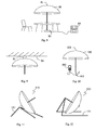
- Fig. 8 illustrates a speaker device making use of a parasol canopy 80 as a membrane.
- a transducer 81 is attached at the top of the canopy, and connected by means of internal wiring through a central shaft 82 to a connector 83 for audio input.
- a Hi-Fi equipment 84 is connected by cable to connector 83. Music or other audio content played by equipment 84 will be provided through the canopy membrane 80, and by mainly focused downwards. This way, a rich sound can be obtained for the people sitting at the parasol, while not bothering others in the vicinity. In this sense, the speaker device is directional.
- the parasol is preferably foldable and provided with a generally flexible canopy 80, but need not be.
- Fig. 9 illustrates a speaker device in mounted to a ceiling 90, e.g. in a conference room, with the transducer 91 at the centre of the speaker membrane.
- wiring is led from transducer 91 to an audio signal input for connection to e.g. a Hi-Fi equipment or a conference telephone.
- the speaker device when used for this basically stationary purpose, need not be foldable.
- Fig. 10 illustrates an embodiment where the speaker device is incorporated in an umbrella, with the umbrella canopy 100 acting as the membrane.
- the drawing illustrates schematically how a mobile phone 103 is connected from a speaker output connector and via a cable to an audio input connector 102 at the umbrella handle. Audio input connector 102 is internally connected to transducer 101.
- the speaker device may in this configuration be used as a loudspeaker when using the phone 103, but perhaps more preferably when using a built-in music player in the phone 103. It could in this context be noted that the narrow idea of combining a speaker with an umbrella has been suggested before by Nesbit in U.S. Patent 4,915,670 . However, in that case the umbrella canopy was simply a carrier for attached auxiliary speakers, and did not act as the membrane itself.
- Figs 11 and 12 illustrate two different concepts for mounting members, usable for placing the speaker device on a support surface such as a desktop or a floor.
- the tripod 111 of Fig. 11 attached at the top of side of the membrane of the speaker device 110, and the long feet arrangement 121 of Fig. 12 attached to the central shaft of the speaker device 120 are easily made foldable by use of suitable joints and hinges.
- the mounting members are devised for placing the speaker device with its membrane facing at least partly horizontally.
- a main sound output direction can be defined for the speaker device, basically the direction of the central support member 12 for a design such as that of Fig. 2, which main direction is tilted from a vertical direction.
- An alternative embodiment may include a spike for penetrating the ground, such that the speaker device can be conveniently arranged outdoors.
- Fig. 13 discloses a typical way of operating a speaker device according to the embodiment of Fig. 12.
- a portable speaker device 120 with a foldable mounting member 121 is connected to a mobile phone 130 by suitable connection means 131.
- a speaker cable 131 is used, but in an alternative embodiment a wireless connection means 131 using IR or radio, may be used, by including an adapted receiver in the speaker device 120.
- Fig. 14 illustrates a setup similar to that of Fig. 13, but where the audio device is an mp3 player 140, an where a stereo cable 141 is used, connected to two speaker devices 120.
- Fig. 15 illustrates another setup similar to that of Fig. 13, but where a speaker device 70 as illustrated in Fig. 7 is instead used, having a mounting member 151 which preferably is foldable.
Landscapes
- Engineering & Computer Science (AREA)
- Physics & Mathematics (AREA)
- Acoustics & Sound (AREA)
- Signal Processing (AREA)
- Multimedia (AREA)
- Audible-Bandwidth Dynamoelectric Transducers Other Than Pickups (AREA)
Abstract
Speaker device (10), comprising a transducer (18) devised to convert an electric signal into mechanical movement, a membrane (11), and a support structure (12,13,14,15) for the membrane, wherein the support structure is convertible between an active mode at which the membrane is held in a stretched state, and an inactive mode at which the membrane is folded. The support structure preferably has a central shaft (12) about which the membrane is suspended in an umbrella-like manner, with the transducer is connected to the central shaft.
Description
- The present invention relates to the field of speakers for audio players, devised to convert electric signals to sound waves. More particularly, the invention relates to a compact speaker solution which has excellent low frequency performance for its size and weight.
- The traditional speaker design involves a transducer, devised to transform electric signals to mechanical movement, attached to a membrane which transfers the movement of the transducer to a movement of a mass of air. The speaker is generally mounted in a box or baffle in order to avoid short-cutting the sound. As a result, low and mid range audio frequencies will be muted, dependent on the size of the speaker and the box. Low frequency sound, commonly referred to a bass, means long waves compared to high frequency sound, and therefore requires larger boxes. The bigger the box or baffle is, the better the low frequency performance will typically be.
- Obviously, size will at one point or another be a limiting issue, dependent on the intended use of the speaker. Furthermore, since the speaker box also needs to be rigid to avoid or at least limit unwanted resonances in the box, also the weight will increase with the size of the speaker box or baffle.
- A general object of the invention is to provide an improved speaker solution, providing good low frequency sound performance, and at the same time being compact and lightweight. An aspect of this object is to provide a speaker solution which is suitable for portable use.
- According to a first aspect of the invention, this object is fulfilled by a speaker device, comprising a transducer devised to convert an electric signal into mechanical movement, a membrane, and a support structure for the membrane, wherein the membrane is flexible, and held in a stretched state by the support structure.
- Preferably, the transducer is connected to the support structure.
- In one embodiment the support structure has a central support member and at least one suspension member connected between the membrane and the central support member.
- Preferably, the support structure has at least one spoke extending along the membrane between the central support member and a peripheral portion of the membrane, to which spoke the suspension member connects.
- In one embodiment the suspension member is a strut.
- In a preferred embodiment, the support structure has a central shaft about which the membrane is suspended in an umbrella-like manner.
- Preferably, the transducer is attached to the central shaft.
- In one embodiment the membrane forms a dome-shaped canopy in the stretched state.
- In one embodiment the support structure has a mounting member for placing the speaker device with its membrane facing at least partly horizontally.
- Preferably, the mounting member is foldable.
In one embodiment the membrane is a canopy of an umbrella or parasol. - According to a second aspect of the invention, the object of the invention is fulfilled by a speaker device, comprising a transducer devised to convert an electric signal into mechanical movement, a membrane, and a support structure for the membrane, wherein the support structure is convertible between an active mode at which the membrane is held in a stretched state, and an inactive mode at which the membrane is folded.
- In one embodiment, the transducer is connected to the support structure.
- In one embodiment, the support structure has a central support member and at least one suspension member which is connected to the membrane and displacable along the central support member for folding and unfolding the membrane.
- In one embodiment, the support structure has at least one spoke extending along the membrane between the central support member and a peripheral portion of the membrane, to which spoke the suspension member connects.
- In one embodiment, the suspension member is a strut.
- In one embodiment, the support structure has a central shaft about which the membrane is suspended in an umbrella-like manner.
- In one embodiment, the transducer is attached to the central shaft.
- In one embodiment, the membrane forms a dome-shaped canopy in the stretched state.
- In one embodiment, the support structure has a mounting member for placing the speaker device with its membrane facing at least partly horizontally.
- In one embodiment, the mounting member is foldable.
- In one embodiment, the membrane is a canopy of an umbrella or parasol.
- In one embodiment, the membrane is flexible.
- The features and advantages of the present invention will be more apparent from the following description of the preferred embodiments with reference to the accompanying drawings, on which
- Fig. 1 schematically illustrates a first embodiment of an umbrella-like speaker according to the invention, as seen from underneath;
- Fig. 2 schematically illustrates the embodiment of Fig. 1 from a cross-sectional side view;
- Fig. 3 schematically illustrates the embodiment of Figs 1 and 2 from a cross-sectional side view, in a folded state;
- Fig. 4 schematically illustrates a second embodiment of speaker according to the invention, as seen from underneath;
- Fig. 5 schematically illustrates the embodiment of Fig. 4 from a cross-sectional side view;
- Fig. 6 schematically illustrates the embodiment of Figs 4 and 5 from a cross-sectional side view, in a folded state;
- Fig. 7 schematically illustrates an alternative to the embodiment of Fig. 5; and
- Figs 8-15 schematically illustrates different fields of use and ways of mounting a speaker according to the invention;
- The present description relates to the field of loudspeakers for converting electric audio signals, provided by an audio device, into sound. The proposed speaker is usable together with any type of audio player having an output for a speaker signal, such as traditional stationary Hi-Fi equipment or a radio receiver. The speaker is also usable for providing real time sound from a microphone or similar, through suitable amplifying means. In particular, the invention has significant benefits as a portable speaker. As such, it may be used for transport between different sound sources, but even more advantageously, it may be carried along together with portable audio devices, such as portable radio receivers, MD or CD players, mp3 players and so on. It should be emphasised that the term comprising or comprises, when used in this description and in the appended claims to indicate included features, elements or steps, is in no way to be interpreted as excluding the presence of other features elements or steps than those expressly stated.
- The present invention relates to a speaker design, which involves a membrane with a relatively large surface. The membrane is attached to a support structure, but the speaker device does not need to include any box or baffle, and is therefore also lightweight. A transducer is used to convert electric audio signals into mechanical movement. The transducer may be attached to the membrane, but is preferably attached or built into the support structure, which in turn supports the membrane. The membrane may be such that it would fold or collapse unless held in the stretched state by the support structure, such as a flexible cloth or a pre-folded element. Exemplary embodiments will now be described with references made to the accompanying drawing.
- Figs 1-3 illustrate a first embodiment of a
speaker device 10, having an umbrella-like structure, which makes it possible to collapse the speaker to a very compact format. In Fig. 1 thespeaker device 10 is depicted in an active, unfolded state from what would correspond to the bottom side of an umbrella, which is a main sound output direction for the speaker.Speaker device 10 includes amembrane 11 carried by a support structure. The support structure includes acentral support member 12 attached to the membrane. Eight spoke-like members 13, hereinafter called spokes, project substantially radially from thecentral support member 12, in engagement withmembrane 11. Dashed line A--A indicate the cross-sectional side view from which Fig. 2 is taken. In Fig. 2, the umbrella-like appearance of the speaker device is even more clear.Central support member 12 includes a shaft extending substantially parallel to the main sound output direction ofspeaker device 10. A foldingmember 15 forms part of thecentral support member 12, and is displacable along the shaft of the central support member for folding and unfolding thespeaker device 10. At least one suspension member in the form of astrut 14 is connected between foldingmember 15 andspokes 13. As is well known from the traditional umbrella design, one strut may be included for each or e.g. every second spoke. Furthermore, the design may involve any number of spokes. The strut may also be divided into several parts linked together, as is e.g. common for compact umbrellas. - In the position shown in Figs 1 and 2, the speaker is shown in its active mode, meaning that
membrane 11 is held in a stretched state and thus usable for conveying sound. This is achieved by foldingmember 15 being placed in an upper position, whereby struts 14 force spokes outwardly. Foldingmember 15 is preferably fixed in the upper position by alock mechanism 16. The spokes are typically slightly flexible, and the shape ofmembrane 11 and the tension caused by stretching it, will therefore bend the spokes as illustrated. The material ofmembrane 11 is preferably flexible but substantially non-resilient. In an alternative embodiment, the membrane is a pre-folded element, similar to a lamp-shade, which typically assumes a generally cylindrical tube shape when folded. By expanding one end of that tube, the membrane will unfold to a pyramid shape. For a design with a flexible non-resilient membrane, such as a cloth, the shape obtained in the unfolded state is predominantly determined by how the membrane is cut, and the support structure is preferably designed such that tension is maintained throughout the entire membrane. Fig. 1 illustrates a dome-shaped membrane, which has shown excellent results in tests, but other shapes are also possible, such as a flat membrane, or a sail-shaped membrane, e.g. a spinnaker. In order to create sound waves, atransducer 18 is connected to the support structure. In the illustrated embodiment,transducer 18 is attached at a top portion of thecentral support member 12.Transducer 18 may alternatively be built into the support structure, or e.g. be attached at a side portion of the shaft ofcentral support member 12. When acoustic waves are induced in the support structure by means oftransducer 18,membrane 11 will be forced to follow, and thereby set the air surrounding themembrane 11 in motion. As a result, sound waves are emitted. In a traditional speaker, the membrane is generally non-flexible and its movement is piston-like. The present invention, in an embodiment such as that of Fig. 2 with a flexible and potentially foldable membrane, is believed to work differently, in that sound waves instead will propagate from the centrally placed transducer and radially outwards along the membrane. In tests made on an ordinary umbrella, fitted with atransducer 18 in a position as illustrated in the drawing of Fig. 2 and connected to an audio player, surprisingly rich and deep sound quality has been obtained. Particularly the low frequency performance has been surprisingly good. - Fig. 3 illustrates
speaker device 10 in an inactive mode, where it is folded such that there is no tension in themembrane 11. This folded position is obtained by releasinglock mechanism 16 and displacing foldingmember 15 downwards.Struts 14 are thereby forced to pull and pivot thespokes 13 towards the shaft ofcentral support member 12. In order for this to be possible,spokes 13 are preferably hinged tocentral support member 12, and struts 14 are preferably also hinged both tospokes 13 and to foldingmember 15. - Figs 4-6 illustrate a second embodiment of the speaker device according to the invention, where Figs 4 and 5 show the speaker in the active mode and Fig. 6 in the inactive mode. In Fig. 4 the
speaker device 40 is illustrated perpendicular to itsmembrane 41. As is shown more clearly in Fig. 5, seen from a cross-sectional side view indicated by dashed line B--B in Fig. 4,membrane 41 is substantially flat in this embodiment in its unfolded state.Membrane 41 is held by a support structure comprising a central support member with ashaft 42, and a foldingmember 45 corresponding to foldingmember 15 of the first embodiment. In this embodiment, however,shaft 42 of the central support is not by necessity attached to themembrane 41, even if it may be as will exemplified below. In the illustrated embodiment of Figs 4-6,membrane 41 is only suspended in peripheral portions byspokes 43, arranged underneath the membrane and extend at an angle away from the membrane to a pivotable connection point at the central support member. Suspension members in the form ofstruts 44 are connected between foldingmember 45 andspokes 44, such that displacement of foldingmember 45 downwards to the preferably locked position shown in Fig. 5pivots spokes 43 to stretchmembrane 41. Sincespokes 43 do not extend in engagement withmembrane 41, and are subjected to pulling and bending forces at connection points 47 tostruts 44,spokes 43 are preferably substantially non-resilient. Atransducer 48 is connected to the support structure to convey mechanical movement tomembrane 41, for emitting sound waves. In the illustrated embodiment,transducer 48 is connected to aspoke 43, at a position where the spoke is attached tomembrane 41. - Fig. 7 illustrates an alternative to the embodiment of Figs 4-6, in the active mode, also using the same reference numbers for like features. The difference is that in this
speaker device 70membrane 41 is also attached to the top ofcentral portion 42, similar to the first embodiment shown in Figs 1-3. Preferably,transducer 48 is also placed at the top portion of the central portion, close to themembrane 41. The speaker device may be designed such thatmembrane 41 is flat in the unfolded, stretched, state also in this embodiment, by the point of attachment of thecentral portion 42 tomembrane 41 being flush with a plane defined by the points of connection betweenspokes 43 andmembrane 41. However, in the illustrated embodiment, the point at whichmembrane 41 attaches tocentral portion 42 is somewhat lower than the plane defined by the points of connection betweenspokes 43 andmembrane 41. In the stretched state as shown in Fig. 14,membrane 41 will slope slightly inwardly towards the centre. - Fig. 6 illustrates
speaker device 40 in the inactive mode. This folded position is obtained by releasing alock mechanism 46 and displacing foldingmember 45 upwards.Struts 44 are thereby forced to push andpivot spokes 43 to collapse themembrane 41.Spokes 43 are preferably hinged tocentral support member 42, and struts 44 are preferably also hinged both tospokes 43 and to foldingmember 45. - As is illustrated in both Figs 3 and 6, the membrane of the speaker device will be non-stretched in the folded state, and the entire speaker device will be extremely compact. The speaker device may for example be transported in a protective cylinder casing.
- The speaker device as shown in the drawings is also devised with either an input for an electric audio signal, connected to the
transducer 18, or incorporate a built-in audio device, such as a radio or a music player. - Even though the speaker device in one embodiment resembles an umbrella, that type of embodiment does not necessarily have to be an umbrella. If the purpose is to provide a compact portable speaker for connection to a music player, such as a CD player or a mobile phone incorporating e.g. an mp3 player, the size of a speaker device need not be as large as a traditional umbrella, but rather with an unfolded diameter in the range of 5-50 cm.
- Furthermore, the membrane need not be designed to withstand rain and strong wind, but can be made from any material suitable for it to act as a speaker membrane, such as thin plastics high performance membrane material, or a woven material. To further improve the sound performance the membrane surface may be enforced, e.g. at the outer edges.
- The shape of the membrane may basically take any shape from triangular or rectangular, to multisided or circular, and it does not have to be symmetrical. As mentioned and as shown in the drawings, the surface of the membrane may also take different shapes, such as flat, conical, pyramid-shaped or dome-shaped.
- The transducer used in the speaker device may be an electro-dynamic transducer, a piezo-electric transducer, or an electrostatic transducer, but need not be restricted to these types.
- Different fields of use of a speaker according to the invention will now be described be reference to Figs 8-15, in which the speaker device is shown only schematically.
- Fig. 8 illustrates a speaker device making use of a
parasol canopy 80 as a membrane. Atransducer 81 is attached at the top of the canopy, and connected by means of internal wiring through a central shaft 82 to aconnector 83 for audio input. A Hi-Fi equipment 84 is connected by cable toconnector 83. Music or other audio content played byequipment 84 will be provided through thecanopy membrane 80, and by mainly focused downwards. This way, a rich sound can be obtained for the people sitting at the parasol, while not bothering others in the vicinity. In this sense, the speaker device is directional. The parasol is preferably foldable and provided with a generallyflexible canopy 80, but need not be. - Fig. 9 illustrates a speaker device in mounted to a
ceiling 90, e.g. in a conference room, with thetransducer 91 at the centre of the speaker membrane. Typically, wiring is led fromtransducer 91 to an audio signal input for connection to e.g. a Hi-Fi equipment or a conference telephone. The speaker device, when used for this basically stationary purpose, need not be foldable. - Fig. 10 illustrates an embodiment where the speaker device is incorporated in an umbrella, with the
umbrella canopy 100 acting as the membrane. The drawing illustrates schematically how amobile phone 103 is connected from a speaker output connector and via a cable to anaudio input connector 102 at the umbrella handle.Audio input connector 102 is internally connected totransducer 101. The speaker device may in this configuration be used as a loudspeaker when using thephone 103, but perhaps more preferably when using a built-in music player in thephone 103. It could in this context be noted that the narrow idea of combining a speaker with an umbrella has been suggested before by Nesbit inU.S. Patent 4,915,670 . However, in that case the umbrella canopy was simply a carrier for attached auxiliary speakers, and did not act as the membrane itself. - Figs 11 and 12 illustrate two different concepts for mounting members, usable for placing the speaker device on a support surface such as a desktop or a floor. Though not shown in detail, the
tripod 111 of Fig. 11 attached at the top of side of the membrane of thespeaker device 110, and thelong feet arrangement 121 of Fig. 12 attached to the central shaft of thespeaker device 120, are easily made foldable by use of suitable joints and hinges. Common for the embodiments of Figs 11 and 12 is that the mounting members are devised for placing the speaker device with its membrane facing at least partly horizontally. By facing at least partly horizontally is meant that a main sound output direction can be defined for the speaker device, basically the direction of thecentral support member 12 for a design such as that of Fig. 2, which main direction is tilted from a vertical direction. An alternative embodiment may include a spike for penetrating the ground, such that the speaker device can be conveniently arranged outdoors. - Fig. 13 discloses a typical way of operating a speaker device according to the embodiment of Fig. 12. In this case, a
portable speaker device 120 with a foldable mountingmember 121 is connected to amobile phone 130 by suitable connection means 131. Typically, aspeaker cable 131 is used, but in an alternative embodiment a wireless connection means 131 using IR or radio, may be used, by including an adapted receiver in thespeaker device 120. - Fig. 14 illustrates a setup similar to that of Fig. 13, but where the audio device is an mp3 player 140, an where a
stereo cable 141 is used, connected to twospeaker devices 120. - Fig. 15 illustrates another setup similar to that of Fig. 13, but where a
speaker device 70 as illustrated in Fig. 7 is instead used, having a mountingmember 151 which preferably is foldable. - It should of course be noted that the different embodiments shown in the drawings can be combined in different ways for adapting them to the different modes of operation shown in Fig 8-15. Furthermore, it should be kept in mind that the drawings and description disclose selected embodiments, whereas modifications may be made while still providing the same effects using substantially the same means. As an example, folding need not necessarily be achieved by sliding a folding member along a shaft, which is the traditional umbrella mechanism. A variant could instead involve a lever mechanism. Nevertheless, an extremely compact design for a speaker, particularly when not in use, is provided by the proposed foldable embodiment. The invention should therefore not be construed as being limited to the particular embodiments discussed above, which are illustrative rather than restrictive, and it should be appreciated that variations may be made in those embodiments by persons skilled in the art, without departing from the scope of the present invention as defined by the appended claims.
Claims (23)
- Speaker device (10), comprising a transducer (18) devised to convert an electric signal into mechanical movement, a membrane (11), and a support structure (12,13,14,15) for the membrane, characterised in that the membrane is flexible, and held in a stretched state by the support structure.
- The speaker device as recited in claim 1, characterised in that the transducer is connected to the support structure.
- The speaker device as recited in claim 1, characterised in that the support structure has a central support member (12) and at least one suspension member (14) which is connected between the membrane and the central support member.
- The speaker device as recited in claim 3, characterised in that the support structure has at least one spoke (13) extending along the membrane between the central support member and a peripheral portion of the membrane, to which spoke the suspension member connects.
- The speaker device as recited in claim 3, characterised in that the suspension member is a strut (14).
- The speaker device as recited in claim 1, characterised in that the support structure has a central shaft (12) about which the membrane is suspended in an umbrella-like manner.
- The speaker device as recited in claim 6, characterised in that the transducer is attached to the central shaft.
- The speaker device as recited in claim 1, characterised in that the membrane forms a dome-shaped canopy in the stretched state.
- The speaker device as recited in claim 1, characterised in that the support structure has a mounting member (121) for placing the speaker device (120) with its membrane facing at least partly horizontally.
- The speaker device as recited in claim 9, characterised in that the mounting member is foldable.
- The speaker device as recited in claim 1, characterised in that the membrane is a canopy (100,80) of an umbrella or parasol.
- Speaker device (10), comprising a transducer (18) devised to convert an electric signal into mechanical movement, a membrane (11), and a support structure (12,13,14,15) for the membrane, characterised in that the support structure is convertible between an active mode at which the membrane is held in a stretched state, and an inactive mode at which the membrane is folded.
- The speaker device as recited in claim 12, characterised in that the transducer is connected to the support structure.
- The speaker device as recited in claim 12, characterised in that the support structure has a central support member (12) and at least one suspension member (14) which is connected to the membrane and displacable along the central support member for folding and unfolding the membrane.
- The speaker device as recited in claim 14, characterised in that the support structure has at least one spoke (13) extending along the membrane between the central support member and a peripheral portion of the membrane, to which spoke the suspension member connects.
- The speaker device as recited in claim 14, characterised in that the suspension member is a strut (14).
- The speaker device as recited in claim 12, characterised in that the support structure has a central shaft (12) about which the membrane is suspended in an umbrella-like manner.
- The speaker device as recited in claim 17, characterised in that the transducer is attached to the central shaft.
- The speaker device as recited in claim 12, characterised in that the membrane forms a dome-shaped canopy in the stretched state.
- The speaker device as recited in claim 12, characterised in that the support structure has a mounting member (121) for placing the speaker device (120) with its membrane facing at least partly horizontally.
- The speaker device as recited in claim 20, characterised in that the mounting member is foldable.
- The speaker device as recited in claim 12, characterised in that the membrane is a canopy (100,80) of an umbrella or parasol.
- The speaker device as recited in claim 12, characterised in that the membrane is flexible.
Priority Applications (1)
| Application Number | Priority Date | Filing Date | Title |
|---|---|---|---|
| EP05103159A EP1732355A1 (en) | 2005-04-20 | 2005-04-20 | Foldable speaker |
Applications Claiming Priority (1)
| Application Number | Priority Date | Filing Date | Title |
|---|---|---|---|
| EP05103159A EP1732355A1 (en) | 2005-04-20 | 2005-04-20 | Foldable speaker |
Publications (1)
| Publication Number | Publication Date |
|---|---|
| EP1732355A1 true EP1732355A1 (en) | 2006-12-13 |
Family
ID=34981283
Family Applications (1)
| Application Number | Title | Priority Date | Filing Date |
|---|---|---|---|
| EP05103159A Withdrawn EP1732355A1 (en) | 2005-04-20 | 2005-04-20 | Foldable speaker |
Country Status (1)
| Country | Link |
|---|---|
| EP (1) | EP1732355A1 (en) |
Cited By (2)
| Publication number | Priority date | Publication date | Assignee | Title |
|---|---|---|---|---|
| CN101026894B (en) * | 2007-03-15 | 2011-06-29 | 成都统领万达工贸有限公司 | Multifunctional mobile audio |
| US12142254B1 (en) * | 2023-06-26 | 2024-11-12 | King Faisal University | Umbrella microphone with soundproofing |
Citations (3)
| Publication number | Priority date | Publication date | Assignee | Title |
|---|---|---|---|---|
| GB229382A (en) * | 1923-11-19 | 1925-02-19 | Henry Joseph Round | Improvements in loud speakers |
| JPS5533351A (en) * | 1978-08-30 | 1980-03-08 | Olympus Optical Co Ltd | Folding type cone speaker |
| US4915670A (en) * | 1988-05-23 | 1990-04-10 | Nesbit Mark S | Radio equipped umbrella |
-
2005
- 2005-04-20 EP EP05103159A patent/EP1732355A1/en not_active Withdrawn
Patent Citations (3)
| Publication number | Priority date | Publication date | Assignee | Title |
|---|---|---|---|---|
| GB229382A (en) * | 1923-11-19 | 1925-02-19 | Henry Joseph Round | Improvements in loud speakers |
| JPS5533351A (en) * | 1978-08-30 | 1980-03-08 | Olympus Optical Co Ltd | Folding type cone speaker |
| US4915670A (en) * | 1988-05-23 | 1990-04-10 | Nesbit Mark S | Radio equipped umbrella |
Non-Patent Citations (1)
| Title |
|---|
| PATENT ABSTRACTS OF JAPAN vol. 004, no. 063 (E - 010) 13 May 1980 (1980-05-13) * |
Cited By (2)
| Publication number | Priority date | Publication date | Assignee | Title |
|---|---|---|---|---|
| CN101026894B (en) * | 2007-03-15 | 2011-06-29 | 成都统领万达工贸有限公司 | Multifunctional mobile audio |
| US12142254B1 (en) * | 2023-06-26 | 2024-11-12 | King Faisal University | Umbrella microphone with soundproofing |
Similar Documents
| Publication | Publication Date | Title |
|---|---|---|
| CN113573215B (en) | Loudspeaker diaphragm, loudspeaker and audio device | |
| US10893366B1 (en) | Audio device with dynamic microphone and speaker | |
| US9596530B2 (en) | Configurable speaker | |
| US8867771B2 (en) | Portable vibration speaker | |
| US7282633B1 (en) | Sound augmentation system and method for a drum | |
| JPH09215087A (en) | Sound signal receiving device | |
| EP1732355A1 (en) | Foldable speaker | |
| US8155372B2 (en) | Wire suspension for speakers | |
| CN204046767U (en) | Portable audio amplifier | |
| CN218959099U (en) | Sound equipment, sunshade umbrella, swing and tent | |
| US6381337B1 (en) | Sound reproduction device or microphone | |
| JP5923213B1 (en) | Loudspeakers for portable electronic devices | |
| KR101627218B1 (en) | Slim speaker having variable space | |
| US20040120542A1 (en) | Loudspeaker with a bellow-shaped surround | |
| CN222802963U (en) | A speaker with low noise and strong sound layering | |
| KR102203141B1 (en) | All-in-one instrument case for amplifier and stand | |
| CN215773506U (en) | Multifunctional earphone head clip | |
| CN207505128U (en) | A kind of loud speaker bilayer dust cover structure | |
| CN221768205U (en) | An anti-interference household Bluetooth speaker | |
| CN220776024U (en) | Outdoor entertainment sound box | |
| CN205408127U (en) | Take stereo set of projecting apparatus | |
| CN205081957U (en) | speaker | |
| CN219107602U (en) | Multifunctional stage sound equipment | |
| CN214384715U (en) | Improved structure of loudspeaker | |
| CN210202021U (en) | Portable rotatable look screen audio amplifier |
Legal Events
| Date | Code | Title | Description |
|---|---|---|---|
| PUAI | Public reference made under article 153(3) epc to a published international application that has entered the european phase |
Free format text: ORIGINAL CODE: 0009012 |
|
| AK | Designated contracting states |
Kind code of ref document: A1 Designated state(s): AT BE BG CH CY CZ DE DK EE ES FI FR GB GR HU IE IS IT LI LT LU MC NL PL PT RO SE SI SK TR |
|
| AX | Request for extension of the european patent |
Extension state: AL BA HR LV MK YU |
|
| AKX | Designation fees paid | ||
| REG | Reference to a national code |
Ref country code: DE Ref legal event code: 8566 |
|
| STAA | Information on the status of an ep patent application or granted ep patent |
Free format text: STATUS: THE APPLICATION IS DEEMED TO BE WITHDRAWN |
|
| 18D | Application deemed to be withdrawn |
Effective date: 20060614 |