EP1732293A1 - Radio communication system, fixed information device, and mobile terminal device - Google Patents
Radio communication system, fixed information device, and mobile terminal device Download PDFInfo
- Publication number
- EP1732293A1 EP1732293A1 EP05719546A EP05719546A EP1732293A1 EP 1732293 A1 EP1732293 A1 EP 1732293A1 EP 05719546 A EP05719546 A EP 05719546A EP 05719546 A EP05719546 A EP 05719546A EP 1732293 A1 EP1732293 A1 EP 1732293A1
- Authority
- EP
- European Patent Office
- Prior art keywords
- radio communication
- mobile terminal
- terminal device
- unit
- stationary information
- Prior art date
- Legal status (The legal status is an assumption and is not a legal conclusion. Google has not performed a legal analysis and makes no representation as to the accuracy of the status listed.)
- Withdrawn
Links
Images



Classifications
-
- H—ELECTRICITY
- H04—ELECTRIC COMMUNICATION TECHNIQUE
- H04M—TELEPHONIC COMMUNICATION
- H04M1/00—Substation equipment, e.g. for use by subscribers
- H04M1/60—Substation equipment, e.g. for use by subscribers including speech amplifiers
- H04M1/6033—Substation equipment, e.g. for use by subscribers including speech amplifiers for providing handsfree use or a loudspeaker mode in telephone sets
- H04M1/6041—Portable telephones adapted for handsfree use
- H04M1/6075—Portable telephones adapted for handsfree use adapted for handsfree use in a vehicle
-
- B—PERFORMING OPERATIONS; TRANSPORTING
- B60—VEHICLES IN GENERAL
- B60R—VEHICLES, VEHICLE FITTINGS, OR VEHICLE PARTS, NOT OTHERWISE PROVIDED FOR
- B60R11/00—Arrangements for holding or mounting articles, not otherwise provided for
- B60R11/02—Arrangements for holding or mounting articles, not otherwise provided for for radio sets, television sets, telephones, or the like; Arrangement of controls thereof
-
- B—PERFORMING OPERATIONS; TRANSPORTING
- B60—VEHICLES IN GENERAL
- B60R—VEHICLES, VEHICLE FITTINGS, OR VEHICLE PARTS, NOT OTHERWISE PROVIDED FOR
- B60R11/00—Arrangements for holding or mounting articles, not otherwise provided for
- B60R2011/0042—Arrangements for holding or mounting articles, not otherwise provided for characterised by mounting means
- B60R2011/0049—Arrangements for holding or mounting articles, not otherwise provided for characterised by mounting means for non integrated articles
- B60R2011/005—Connection with the vehicle part
- B60R2011/0052—Connection with the vehicle part using screws, bolts, rivets or the like
-
- B—PERFORMING OPERATIONS; TRANSPORTING
- B60—VEHICLES IN GENERAL
- B60R—VEHICLES, VEHICLE FITTINGS, OR VEHICLE PARTS, NOT OTHERWISE PROVIDED FOR
- B60R11/00—Arrangements for holding or mounting articles, not otherwise provided for
- B60R2011/0042—Arrangements for holding or mounting articles, not otherwise provided for characterised by mounting means
- B60R2011/0049—Arrangements for holding or mounting articles, not otherwise provided for characterised by mounting means for non integrated articles
- B60R2011/0064—Connection with the article
- B60R2011/007—Connection with the article using magnetic means
-
- B—PERFORMING OPERATIONS; TRANSPORTING
- B60—VEHICLES IN GENERAL
- B60R—VEHICLES, VEHICLE FITTINGS, OR VEHICLE PARTS, NOT OTHERWISE PROVIDED FOR
- B60R11/00—Arrangements for holding or mounting articles, not otherwise provided for
- B60R2011/0042—Arrangements for holding or mounting articles, not otherwise provided for characterised by mounting means
- B60R2011/0049—Arrangements for holding or mounting articles, not otherwise provided for characterised by mounting means for non integrated articles
- B60R2011/0078—Quick-disconnect two-parts mounting means
-
- B—PERFORMING OPERATIONS; TRANSPORTING
- B60—VEHICLES IN GENERAL
- B60R—VEHICLES, VEHICLE FITTINGS, OR VEHICLE PARTS, NOT OTHERWISE PROVIDED FOR
- B60R11/00—Arrangements for holding or mounting articles, not otherwise provided for
- B60R11/02—Arrangements for holding or mounting articles, not otherwise provided for for radio sets, television sets, telephones, or the like; Arrangement of controls thereof
- B60R2011/0282—Arrangements for holding or mounting articles, not otherwise provided for for radio sets, television sets, telephones, or the like; Arrangement of controls thereof for the use of several passengers, e.g. simultaneously
-
- B—PERFORMING OPERATIONS; TRANSPORTING
- B60—VEHICLES IN GENERAL
- B60R—VEHICLES, VEHICLE FITTINGS, OR VEHICLE PARTS, NOT OTHERWISE PROVIDED FOR
- B60R11/00—Arrangements for holding or mounting articles, not otherwise provided for
- B60R11/02—Arrangements for holding or mounting articles, not otherwise provided for for radio sets, television sets, telephones, or the like; Arrangement of controls thereof
- B60R2011/0288—Apparatus made of several modules independently mounted
-
- B—PERFORMING OPERATIONS; TRANSPORTING
- B60—VEHICLES IN GENERAL
- B60R—VEHICLES, VEHICLE FITTINGS, OR VEHICLE PARTS, NOT OTHERWISE PROVIDED FOR
- B60R11/00—Arrangements for holding or mounting articles, not otherwise provided for
- B60R11/02—Arrangements for holding or mounting articles, not otherwise provided for for radio sets, television sets, telephones, or the like; Arrangement of controls thereof
- B60R2011/0294—Apparatus with multi-functionalities, e.g. radio and telephone
-
- H—ELECTRICITY
- H04—ELECTRIC COMMUNICATION TECHNIQUE
- H04M—TELEPHONIC COMMUNICATION
- H04M1/00—Substation equipment, e.g. for use by subscribers
- H04M1/60—Substation equipment, e.g. for use by subscribers including speech amplifiers
- H04M1/6033—Substation equipment, e.g. for use by subscribers including speech amplifiers for providing handsfree use or a loudspeaker mode in telephone sets
- H04M1/6041—Portable telephones adapted for handsfree use
- H04M1/6075—Portable telephones adapted for handsfree use adapted for handsfree use in a vehicle
- H04M1/6083—Portable telephones adapted for handsfree use adapted for handsfree use in a vehicle by interfacing with the vehicle audio system
- H04M1/6091—Portable telephones adapted for handsfree use adapted for handsfree use in a vehicle by interfacing with the vehicle audio system including a wireless interface
Definitions
- the present invention relates to a radio communication system that performs a radio information communication between a stationary information device and a mobile terminal device, and also to a stationary information device and a mobile terminal device that constitute such a radio communication system.
- a PDA is a small mobile information terminal that includes a microcomputer, a display, a pen-based function, a communication function, and the like.
- An information processing device of this type includes a system in which a mobile terminal device is placed near a distribution device so that a magnetic filed is generated from the distribution device and a switch on the mobile terminal is turned on by the magnetic field if the mobile terminal device is positioned close thereto, at which timing the two devices start communications (refer to Patent Document 1, for example).
- Patent Document 1 Japanese Patent Laid-Open Publication No. 8-278929
- the present invention was conceived in light of the above.
- the purpose of the invention is to achieve a radio communication system capable of reliably attaching a stationary information device and a mobile terminal device to each other with a simple structure and performing radio communications at a higher speed, and a stationary information device and a mobile terminal device that constitute this radio communication system.
- the invention according to claim 1 is a radio communication system that performs a radio communication between a stationary information device and a mobile terminal device.
- the stationary information device includes a first radio communication unit that performs a radio communication to detect an approach of the mobile terminal device; a detecting unit that detects the approach of the mobile terminal device based on a result of the radio communication by the first radio communication unit; and an attracting unit that generates, when the detecting unit detects the approach of the mobile terminal device, an attraction force for attracting and fixing the mobile terminal device.
- the mobile terminal device includes a second radio communication unit that performs a radio communication to detect an approach of the stationary information device; and an attracted unit that is attracted to the attraction force generated by the stationary information device.
- the invention according to claim 7 is a stationary information device that includes a first radio communication unit that performs a radio communication to detect approach of an external device; a detecting unit that detects the approach of the external device based on a result of the radio communication by the first radio communication unit; and an attracting unit that generates, when the detecting unit detects the approach of the external device, an attraction force for attracting and fixing the external device.
- the invention according to claim 13 is a mobile terminal device that includes a first radio communication unit that performs a radio communication to detect an approach of an external device; and an attracted unit that is attracted to an attraction force generated by the external device.
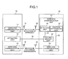
- FIG. 1 is a diagram for explaining the overview of a radio communication system according to the present invention
- Fig. 1 is a diagram for explaining the overview of a radio communication system according to the present invention.
- the radio communication system according to the present invention includes a mobile terminal device 10 that is detachable to be carried around, and a stationary information device 20 that performs information transmission for the mobile terminal device 10.
- the mobile terminal device 10 performs radio communications with the stationary information device 20 and obtains various pieces of information from the stationary information device 20.
- the mobile terminal device 10 includes a radio communication unit 11, an attracted unit 12 that is attracted with an electromagnetic attraction force, and a radio communication unit 13. Moreover, the radio communication unit 11 and the radio communication unit 13 include antenna units 14 and 15, respectively, which transmit and receive radio waves at the time of having radio communications with the stationary information device 20.
- the radio communication unit 11 performs radio communications with a radio communication unit 21 of the stationary information device 20, which will be described later, to detect how close the mobile terminal device 10 and the stationary information device 20 are positioned. Further, the radio communication unit 13 performs high-speed radio communications with a radio communication unit 23 of the stationary information device 20, which will be described later, to exchange information.
- the radio communication unit 11 and the radio communication unit 13 may be designed in such a manner as to operate with electrical power supplied from the power source (not shown) provided in the mobile terminal device 10, or may be designed to operate with electrical power from radio waves transmitted from the stationary information device 20.
- the radio communication unit 11 and the radio communication unit 13 are configured to consume very small transmission power for transmission and reception so that the mobile terminal device 10 can perform radio transmission to a device in its very close vicinity (in the range of less than tens of centimeters or several centimeters, for instance). With the configurations of the radio communication unit 11 and the radio communication unit 13 of the mobile terminal device 10, it barely interferes with other radio devices. Furthermore, improper operations are suppressed during activation of an electromagnet unit 22 as described later, realizing a system operation with high accuracy.
- the radio communication unit 11 and the radio communication unit 13 of the mobile terminal device 10 may be each assigned, for instance, with a personal code number so that the code numbers can be used to distinguish a counterpart device that is a communication target and thereby communicate with the counterpart device. This prevents an improper operation from occurring.
- a radio tag of a passive type is most suitable for the radio communication unit 11 as described above.
- the attracted unit 12 is a portion that is attracted by the electromagnetic attraction force of the electromagnet unit 22 of the stationary information device 20, which will be described later.
- the attracted unit 12 is not particularly limited as long as it is attracted with an electromagnetic attraction force, and can be formed of a metallic material, for example.
- the stationary information device 20 includes the radio communication unit 21, the electromagnet unit 22, and the radio communication unit 23.
- the radio communication unit 21 and the radio communication unit 23 include antenna units 24 and 25, respectively, which perform transmission and reception of radio waves at the time of performing a radio communication with the mobile terminal device 10.
- the radio communication unit 21 performs radio communications with the radio communication unit 11 of the mobile terminal device 10 to detect how close the mobile terminal device 10 and the stationary information device 20 are positioned. Further, the radio communication unit 23 performs high-speed radio communications with the radio communication unit 13 of the mobile terminal unit 10 to exchange information.
- the radio communication unit 21 and the radio communication unit 23 are designed in such a manner as to operate with electrical power supplied from the power source (not shown) provided in the stationary information device 20.
- the radio communication unit 21 and the radio communication unit 23 are configured to consume very small transmission power for transmission and reception so that the stationary information device 20 can perform radio transmission only to a device in its very close vicinity (in the range of less than tens of centimeters or several centimeters, for instance).
- the radio communication unit 21 and the radio communication unit 23 of the stationary information device 20 it barely interferes with other radio devices.
- improper operations are suppressed during activation of the electromagnet unit 22 as described later, realizing a system operation with high accuracy.
- the radio communication unit 21 and the radio communication unit 23 of the stationary information device 20 may be each assigned, for instance, with a personal code number so that the code numbers can be used to distinguish a counterpart device that is a communication target and thereby communicate with the counterpart device. This prevents an improper operation from occurring.
- the electromagnet unit 22 is formed, for example, with an iron core and a winding wire coil unit.
- the electromagnet unit 22 generates an electromagnetic attraction force 33 for fixing the mobile terminal device 10 and the stationary information device 20 to each other by attracting the attracted unit 12 of the mobile terminal device 10.
- the electromagnet unit 22 receives electrical power from the power source (not shown) of the stationary information device.
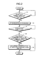
- Fig. 2 is a flowchart for explaining the operation of the radio communication system.
- the mobile terminal device 10 is brought into the close vicinity of the stationary information device 20.
- whether the radio communication unit 21 of the stationary information device 20 receives a radio signal transmitted from the radio communication unit 11 of the mobile terminal device 10 is determined (Step 1).
- the radio communication unit 21 of the stationary information device 20 is unable to detect the mobile terminal device brought in its vicinity, and thus the radio communication unit 21 of the stationary information device 20 stands by until a new radio communication is received.
- the radio communication unit 21 of the stationary information device 20 detects the approach of the mobile terminal device.
- the radio communication unit 21 may be provided inside itself with a detecting unit 26, for example, that detects the approach of the mobile terminal device 10 based on the result of receiving a radio signal, and the detecting unit 26 performs detection using the signal level of the radio signal, a radio transmitted code, or the like.
- the detecting unit 26 may be arranged separately outside the radio communication unit 21.
- the radio communication unit 21 of the stationary information device 20 a unit with the detection distance to the mobile terminal device 10, i.e. the signal reception distance, being as short as possible.
- the receiver sensitivity of the radio communication unit 21 is lowered, which reduces the consumption power of the radio communication unit 21 and enhance power savings.
- a unit with a high receiver sensitivity capable of performing reception in a long-distance range is not required. Because a low-priced radio communication unit with a relatively low receiver sensitivity can be adopted, cost reduction can be achieved.
- the radio communication unit 21 of the stationary information device 20 transmits an activation instruction 31 to the electromagnet unit 22.
- the electromagnet unit 22 activates the electromagnet (Step 2) to generate the electromagnetic attraction force 33.
- the attracted unit 12 of the mobile terminal device 10 is attracted with the electromagnetic attraction force 33 that is generated by the electromagnet unit 22. This brings the mobile terminal device 10 to a state of being in contact with the stationary information device 20, and this electromagnet unit 22 secures the mobile terminal device 10 to the stationary information device 20 with the electromagnetic attraction force 33.
- the mobile terminal device 10 and the stationary information device 20 are not fixed by a complex, mechanical fixing means, but with the electromagnetic attraction force 33 generated by the electromagnet unit 22.
- complex fixing units, fixing members, and the like are required on both the mobile terminal device 10 and the stationary information device 20, which make the structures of the mobile terminal device 10 and the stationary information device 20 complex.
- fixing units and fixing members need to be produced, the design of the equipment becomes complicated, which is a drawback, increasing the manufacturing man-hour and the manufacturing cost.
- the attracted unit 12 provided on the side of the mobile terminal device 10 and the electromagnet unit 22 provided on the side of the stationary information device 20 ensure the fixation of the mobile terminal device 10 to the stationary information device 20 with the electromagnetic attraction force 33 generated by the electromagnet unit 22.
- a complex fixing unit or a fixing member is not required to be arranged on the mobile terminal device 10 and the stationary information device 20 so that the structures of the mobile terminal device 10 and the stationary information device 20 can be simplified and that the mobile terminal device 10 and the stationary information device 20 can be reliably fixed to each other. This lowers the manufacturing man-hour and the manufacturing cost of the mobile terminal device 10 and the stationary information device 20, realizing cost reduction.
- the mobile terminal device 10 and the stationary information device 20 can be reliably fixed to each other with a simple structure.
- the fixation strength of the mobile terminal device 10 and the stationary information device 20 can be readily adjusted by adjusting the intensity of the electromagnetic attraction force 33 generated by the electromagnet unit 22. This allows the radio communication system to be used with the fixation strength of the mobile terminal device 10 and the stationary information device 20 being suitably adjusted in accordance with the environment in which the radio communication system is being used.
- the mobile terminal device 10 and the stationary information device 20 are fixed with a relatively small fixation strength when the vehicle is stopped.
- the intensity of the electromagnetic attraction force 33 generated by the electromagnet unit 22 is adjusted to be weakened.
- the mobile terminal device 10 and the stationary information device 20 are fixed with a larger fixation strength. In such a case, the intensity of the electromagnetic attraction force 33 generated by the electromagnet unit 22 is adjusted to be increased.
- the fixation strength of the mobile terminal device 10 and the stationary information device 20 can be readily adjusted by adjusting the intensity of the electromagnetic attraction force 33 generated by the electromagnet unit 22.
- the adjustment of the intensity of the electromagnetic attraction force 33 generated by the electromagnet unit 22 can be made by adjusting the power supply to the electromagnet unit 22.
- a personal code (a pin number determined by the user) may be input from the side of the mobile terminal device 10 for this purpose.
- Step 3 Whether the mounting of the mobile terminal device 10 on the stationary information device 20 is completed is thereby determined (Step 3).
- the fixation of the mobile terminal device 10 and the stationary information device 20, or the mounting of the mobile terminal device 10 onto the stationary information device 20, is determined as being completed (Step 3, Yes).
- the radio communication unit 11 of the mobile terminal device 10 and the radio communication unit 13 of the stationary information device 20 may stay in operation, or the operation may be stopped after the completion of the fixation of the mobile terminal device 10 and the stationary information device 20 is determined.
- a fixation determining unit 27 that determines the completion of the mounting of the mobile terminal device 10 onto the stationary information device 20, i.e.
- the completion of the attraction and fixation of the mobile terminal device 10 and the stationary information device 20 can be arranged, for example, in the radio communication unit 21 to provide a structure in which the determination is made at the fixation determining unit 27. It is certainly possible to arrange the fixation determining unit 27 separately outside the radio communication unit 21.
- the fixation of the mobile terminal device 10 and the stationary information device 20, i.e. the mounting of the mobile terminal device 10 onto the stationary information device 20, is determined as incomplete (Step 3, No), and the verification processes for mounting are repeated.
- the completion of the mounting of the mobile terminal device 10 onto the stationary information device 20 can be readily checked by arranging a displaying unit or the like that indicates whether it is mounted, in either the mobile terminal device 10 or the stationary information device 20 and controlling it to display.
- the radio communication unit 21 of the stationary information device 20 determines whether high-speed radio communications should be performed at the radio communication unit 23 (Step 4). For the determination as to whether the high-speed radio communications are performed, for example, the user may input into the stationary information device 20 information as to whether standard communications or high-speed radio communications are to be performed, and the determination may be made based on this information. If the high-speed radio communications are determined not to be performed according to the user's information (Step 4, No), the communications are performed at a standard speed.
- the radio communication unit 21 of the stationary information device 20 transmits an instruction 32 of executing high-speed communications to the radio communication unit 23.
- the radio communication unit 23 performs high-speed communications with the radio communication unit 11 of the mobile terminal device 10 (Step 5).
- the mobile terminal device 10 and the stationary information device 20 are fixed in a manner as described above, which brings the distance between the mobile terminal device 10 and the stationary information device 20 to 0.
- the transmission power required for radio transmission between the mobile terminal device 10 and the stationary information device 20 is remarkably small power, theoretically the smallest power to perform radio transmission between the mobile terminal device 10 and the stationary information device 20. It should be noted, however, that this transmission power may vary to some degree depending on conditions such as the distance between the radio communication unit of the mobile terminal device 10 and the radio communication unit of the stationary information device 20.
- radio transmission can be conducted between the mobile terminal device 10 and the stationary information device 20 with a remarkably small transmission power by fixing the mobile terminal device 10 and the stationary information device 20 to each other with the electromagnetic attraction force 33 of the electromagnet unit 22, as described above.
- a broader channel (bandwidth) is required for radio transmission to perform radio transmission at higher speed.
- a channel (bandwidth) allowed for a user is restricted to a specific level by the Radio Law, prohibiting a user from using a bandwidth beyond a specified value so that multiple users are able to use it at the same time.
- the transmission power available for a user is stipulated in a certain range.
- the use of transmission power beyond this stipulated range is considered as interference of other users' radio transmission.
- the present invention is featured in performing radio transmission with an available bandwidth expanded within the aforementioned range of stipulated values by setting the transmission power to a significantly low value.
- the transmission power consumed for a unit bandwidth to a significantly low value, the total transmission power in use stays within the aforementioned range of the stipulated values even when the available bandwidth is expanded.
- the radio communication unit 21 sends the radio communication unit 23 the instruction signal 32 which instructs it to start radio transmission through multiple channels by extending the radio bandwidth used between the radio communication unit of the mobile terminal device 10 and the radio communication unit of the stationary information device 20.
- the radio communication unit of the stationary information device 20 extends the radio bandwidth as indicated in Fig. 3 and starts radio transmission, i.e. high-speed radio communications through multiple channels.
- Fig. 3 indicates use of multiple channels, Channel 1 to Channel 4, in a certain frequency band by using the transmission power X per unit bandwidth (channel) and extending the radio band.
- the broken line Y in Fig. 3 is a line indicating a stipulation value stipulated by the Radio Law, for example.
- radio transmission is performed with a transmission power X in a range Z of frequencies f1 to f2 in the shaded portion.
- a communication method using the entire channel such as a spread spectrum method may be adopted other than the aforementioned method of using multiple channels in parallel that are identical to a channel of the transmission and reception method utilizing a unit bandwidth (channel).
- standard radio communications i.e. radio transmission
- radio transmission which uses a single channel
- a transmission power for a unit bandwidth (channel) is set to a significantly low value
- power saving can be achieved in standard-speed communications .
- the transmission power can be set to a power the least required for radio transmission between the mobile terminal device 10 and the stationary information device 20 by fixing the mobile terminal device 10 and the stationary information device 20 to each other by the electromagnetic attraction force 33 of the electromagnet unit 22, as described above.
- Radio transmission can thereby be performed in an expanded, large bandwidth while complying with the restriction stipulated by the Radio Law and causing no interference with radio transmission of other radio users.
- the radio transmission can be realized at higher speed.
- the radio communication unit 21 may be set to a transmission power smaller than a predetermined value to perform radio communications with, with a radio bandwidth expanded in advance.
- the magnetism of the electromagnet unit 22 is erased by stopping the power supply to the electromagnet unit 22. With the fixation strength eliminated between the mobile terminal device 10 and the stationary information device 20, the mobile terminal device 10 can be detached from the stationary information device 20. Further, the mobile terminal device 10 may be detached from the stationary information device 20 by gradually reducing the power supply to the electromagnet unit 22 with time to gradually weaken the electromagnetic attraction force 33 of the electromagnet unit 22 of the stationary information device 20, thereby weakening the fixation strength between the mobile terminal device 10 and the stationary information device 20.
- the mobile terminal device 10 may be detached from the stationary information device 20 by passing a current of a reversed phase to weaken the fixation strength between the mobile terminal device 10 and the stationary information device 20. Still further, the mobile terminal device 10 may be detached from the stationary information device 20 by inputting a personal code from the side of the mobile terminal device 10 to reduce the electromagnetic attraction force 33 of the electromagnet unit 22 of the stationary information device 20 and thereby weaken the fixation strength between the mobile terminal device 10 and the stationary information device 20.
- the mobile terminal device 10 and the stationary information device 20 are fixed to each other with the electromagnetic attraction force 33 of the electromagnet unit 22 after detecting the approach of the mobile terminal device 10 and the stationary information device 20.
- This ensures the fixation of the mobile terminal device 10 and the stationary information device 20, while simplifying the structures of the mobile terminal device 10 and the stationary information device 20.
- the present invention performs communications with a transmission power smaller than a predetermined level in a communication bandwidth expanded between the mobile terminal device 10 and the stationary information device 20. This allows for high-speed radio communications in an expanded, large bandwidth without causing interference with radio transmission of other radio users.
- an attracted unit metal unit
- the electromagnet unit 22 is arranged on the side of the stationary information device 20
- the present invention is not limited to this configuration, however.
- a structure in which an attracted unit (metal unit) and the electromagnet unit 22 are provided on each of the mobile terminal device 10 and the stationary information device 20 may be adopted.
- a structure in which the electromagnet unit 22 is provided on each of the mobile terminal device 10 and the stationary information device 20 so that the electromagnets are fixed to each other may be adopted.
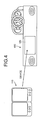
- a radio communication system that performs high-speed radio communications with an electronic-book-type mobile terminal device 110 fixed to a stationary information device 120 that is arranged on the dashboard of a vehicle will be explained, as illustrated in Fig. 4.
- the above explanation should be referred to regarding units similar to the ones that have been explained in the above modes of the invention, and thus detailed description will be omitted.
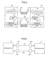
- Fig. 5 is a diagram for explaining the overview of the radio communication system according to the present embodiment.
- the radio communication system according to the present embodiment includes the electronic-book-type mobile terminal device 110 that is detachable and portable, and the stationary information device 120 that transmits information to the electronic-book-type mobile terminal device 110.
- the electronic-book-type mobile terminal device 110 performs radio communications with the stationary information device 120 and obtains various information from the stationary information device 120.
- the electronic-book-type mobile terminal device 110 includes a radio tag 111, a metal unit 112, and a radio communication unit 113. Further, the radio tag 111 and the radio communication unit 113 include antennas 114 and 115, respectively, which perform transmission and reception of radio waves in radio communications with the stationary information device 120.
- the radio tag 111 is designed to detect the approach of the electronic-book-type mobile terminal device 110 and the stationary information device 120 by performing radio communications with an interrogator 121 of the stationary information device 120, which will be discussed later.
- the radio communication unit 113 performs high-speed radio communications with a radio communication unit 123 of the stationary information unit 120, which will be discussed later, to exchange information.
- the metal unit 112 corresponds to the attracted unit 12, and is a unit that is to be attracted by an electromagnetic attraction force of an electromagnet unit 122 of the stationary information device 120, which will be discussed later.
- the stationary information device 120 includes the interrogator 121, the electromagnet unit 122, and the radio communication unit 123.
- the interrogator 121 and the radio communication unit 123 include antennas 124 and 125, respectively, which perform transmission and reception of radio waves in radio communications with the book-type mobile terminal device 110.
- the interrogator 121 is an RFID reader/writer, which corresponds to the aforementioned radio communication unit 21. In other words, it performs radio communications with the radio tag 111 of the book-type mobile terminal device 110 to detect the approach of the book-type mobile terminal device 110 and the stationary information device 120. Further, the radio communication unit 123 performs high-speed radio communications with the radio communication unit 113 of the book-type mobile terminal device 110 to exchange information.
- the interrogator 121 and the radio communication unit 123 are designed in such a manner as to operate with electrical power supplied from the power source (not shown) provided in the stationary information device 20. Moreover, the interrogator 121 and the radio communication unit 123 are configured to have very small transmission power for transmission and reception so that the stationary information device 120 can perform radio transmission to a device in its very close vicinity (in the range of less than several tens of centimeters or several centimeters, for instance). With the configurations of the interrogator 121 and the radio communication unit 123 of the stationary information device 120, it barely interferes with other radio devices. Furthermore, improper operations are suppressed at the time of activating the electromagnet unit 122 as described later, allowing for a system operation with high accuracy.
- the interrogator 121 and the radio communication unit 123 of the stationary information device 20 may be each assigned with a personal code number, for instance, so that the code numbers can be used to distinguish a counterpart device that is a communication target and to communicate with the counterpart device. This prevents an improper operation from occurring.
- the electromagnet unit 122 corresponds to the electromagnet unit 22 and generates an electromagnetic attraction force 133 to attract the metal unit 112 of the book-type mobile terminal device 110 and thereby fix the book-type mobile terminal device 110 and the stationary information device 20.
- the electromagnet unit 122 operates with electric power supplied from the power source (not shown) of the stationary information device.
- the antenna 124b of the interrogator 121 which functions as a reader/writer, transmits to the antenna 114b of the radio tag 111 power to be used in the electronic circuit of the radio tag 111, to the radio tag 111 via a carrier wave 121a.
- the antenna 114a of the radio tag 111 transmits a radio wave 111a modulated in the radio tag 111 to the interrogator 121, which is received by the antenna 124a of the interrogator 121.
- the approach of the book-type mobile terminal device 110 can be thereby detected in accordance with the signal level, code or the like of the received radio wave.
- the interrogator 121 is provided with a function of the above detecting unit.
- the use of two antennas for communications and for power supply is explained here, but they may be replaced with a single antenna.
- the radio tag 111 is not equipped with a power supply for operation. It receives with the antenna 114 the carrier wave 121a sent from the interrogator 121 as described above, rectifies part of the wave at a power-source regenerating circuit 141, and regenerates a power source that is necessary for operation. This process is controlled by an MPU 143. Further, the radio tag 111 is not equipped with a local transmitter for a carrier wave, or the like.
- the radio tag 111 modulates the carrier wave 121a sent from the interrogator 121 at a high-frequency circuit 144 of the radio tag 111 by use of the information written in a memory 142, and sends the signal out to transmit specific information to the interrogator 121.
- the interrogator 121 detects the approach of the mobile terminal device 10 and sends an activation instruction 131 to the electromagnet unit 122.
- the electromagnet unit 122 activates the electromagnet and generates an electromagnetic attraction force 33. Then, because the book-type mobile terminal device 110 is positioned in the close vicinity of the stationary information device 120 at this point, the metal unit 112 of the book-type mobile terminal device 110 is attracted with the electromagnetic attraction force 133 generated by the electromagnet unit 122.
- the fixation strength of the book-type mobile terminal device 110 and the stationary information device 120 can be readily adjusted by adjusting the intensity of the electromagnetic attraction force 133 generated by the electromagnet unit 122.
- the fixation strength of the book-type mobile terminal device 110 and the stationary information device 120 with the electromagnetic attraction force 133 can be increased by detecting the vehicle speed with reference to the vehicle speed pulse or the GPS information and increasing the power supply to the electromagnet unit 122 in accordance with the vehicle speed.
- the book-type mobile terminal device 110 and the stationary information device 120 can thereby be securely fixed to each other even under a condition where the vehicle moves at a high speed and vibration increases, realizing a system excellent in safety.
- the fixation strength of the book-type mobile terminal device 110 and the stationary information device 120 may be adjusted by receiving the information on the surrounding environment other than the vehicle speed, such as the vehicle acceleration and using the environmental information.
- the fixation strength of the book-type mobile terminal device 110 and the stationary information device 120 is weak, the book-type mobile terminal device 110 could be detached and stolen.
- the electromagnetic attraction force 133 of the electromagnet unit 122 is increased to enhance the fixation strength of the book-type mobile terminal device 110 and the stationary information device 120, by inputting a specific code through the book-type mobile terminal device 110 so that the book-type mobile terminal device 110 can be protected against theft.
- the fixation strength of the book-type mobile terminal device 110 and the stationary information device 120 can be set back to the normal level by inputting a specific code through the book-type mobile terminal device 110.
- a configuration is feasible in such that another radio device carried by the user can perform radio communications with the stationary information device 120 so that the user leaving the vehicle can be detected.
- the fixation strength of the book-type mobile terminal device 110 and the stationary information device 120 can thereby be increased to protect the book-type mobile terminal device 110 against theft.
- the mobile device carried by the user performs radio communications with the stationary information device 120 to detect the return of the user to the vehicle so that the fixation strength of the book-type mobile terminal device 110 and the stationary information device 120 can be set back to the normal level.
- the interrogator 121 sends an instruction 132 to the radio communication unit 123 to execute high-speed radio communications.
- the fixation determining unit may be arranged separately outside the interrogator 121.
- the high-speed radio communications are performed with a communication band expanded between the book-type mobile terminal device 110 and the stationary information device 120 in a similar manner to the aforementioned mode of the invention so that the communications can be performed with a transmission power lower than a predetermined level. This allows for high-speed radio communications with an expanded, large bandwidth, without interfering with radio transmission of other radio users.
- directional antennas for the antenna 115 and the antenna 125 and install them in such a manner that the antenna directivity is set in the antenna direction of each other, as illustrated in Fig. 8.
- the directional antennas With the directional antennas, the device itself is protected against interference from outside, and avoids interference with other devices.
- their capability of performing radio transmission stably even with a transmission power set low makes them more preferable.
- the approach of the book-type mobile terminal device 110 and the approach of the stationary information device 120 are detected by use of the radio tag 111 and the interrogator 121, respectively, to fix the book-type mobile terminal device 110 and the stationary information device 120 to each other with the electromagnetic attraction force 133 of the electromagnet unit 122.
- This allows for reliable fixation of the book-type mobile terminal device 110 and the stationary information device 120, while the structures of the book-type mobile terminal device 110 and the stationary information device 120 are designed to be simple.
- communications are performed with a transmission power lower than a predetermined level by expanding the communication band between the book-type mobile terminal device 110 and the stationary information device 120.
- high-speed radio communications can be performed with an expanded, large bandwidth, without interfering with radio transmission of other radio users.
- the structure may be such that, for example, multiple radio tags 152, interrogators 153, electromagnet units 154, and metal units 155 are arranged for mounting of a book-type mobile terminal device 150 onto a stationary information device 151, as illustrated in Fig. 9.
- the structure in Fig. 9 incorporates each unit in pairs.
- Such a structure allows for mounting of the book-type mobile terminal device 150 by detecting the top and bottom sides or left and right sides of the book-type mobile terminal device 150, and prevents failure from occurring, such as the device from being mounted upside down.
- the detachment can be facilitated by switching off the electromagnet unit 154 on the bottom side of the book-type mobile terminal device 150 first.
- the book-type mobile terminal device as a mobile terminal device was explained in the above description.
- the present invention should not be limited thereto, however, and various modes of radio communication devices such as a PDA, a cellular phone, and a card-type audio-visual device may be adopted.
Landscapes
- Engineering & Computer Science (AREA)
- Signal Processing (AREA)
- Mechanical Engineering (AREA)
- Mobile Radio Communication Systems (AREA)
- Telephone Function (AREA)
- Transceivers (AREA)
- Near-Field Transmission Systems (AREA)
- Telephone Set Structure (AREA)
Abstract
Description
- The present invention relates to a radio communication system that performs a radio information communication between a stationary information device and a mobile terminal device, and also to a stationary information device and a mobile terminal device that constitute such a radio communication system.
- Conventionally, information processing devices have been widely used. In recent years, as the size of an information processing device is reduced, various information processing terminals such as a personal digital assistant (PDA) have come into practical use. A PDA is a small mobile information terminal that includes a microcomputer, a display, a pen-based function, a communication function, and the like. An information processing device of this type includes a system in which a mobile terminal device is placed near a distribution device so that a magnetic filed is generated from the distribution device and a switch on the mobile terminal is turned on by the magnetic field if the mobile terminal device is positioned close thereto, at which timing the two devices start communications (refer to Patent Document 1, for example).
- [Patent Document 1]
Japanese Patent Laid-Open Publication No. 8-278929 - However, when such a mobile terminal is used, for example, by attaching it to a distribution device that is fixed inside a vehicle, it is necessary to ensure the attachment so that the terminal would not come off despite vibration created during the movement of the vehicle or the like. In conventional technology, the attachment is made in a mechanical manner, which leads to a problem of, for example, the structure and design of each device being complicated. Thus, it is preferable to adopt an attaching method other than a mechanical attachment. Furthermore, according to the aforementioned conventional technology, a technique of performing high-speed radio communications by use of mobile terminals of this type has not yet been considered, leaving much to be improved regarding a communication speed.
- The present invention was conceived in light of the above. The purpose of the invention is to achieve a radio communication system capable of reliably attaching a stationary information device and a mobile terminal device to each other with a simple structure and performing radio communications at a higher speed, and a stationary information device and a mobile terminal device that constitute this radio communication system.
- The invention according to claim 1 is a radio communication system that performs a radio communication between a stationary information device and a mobile terminal device. The stationary information device includes a first radio communication unit that performs a radio communication to detect an approach of the mobile terminal device; a detecting unit that detects the approach of the mobile terminal device based on a result of the radio communication by the first radio communication unit; and an attracting unit that generates, when the detecting unit detects the approach of the mobile terminal device, an attraction force for attracting and fixing the mobile terminal device. The mobile terminal device includes a second radio communication unit that performs a radio communication to detect an approach of the stationary information device; and an attracted unit that is attracted to the attraction force generated by the stationary information device.
- The invention according to claim 7 is a stationary information device that includes a first radio communication unit that performs a radio communication to detect approach of an external device; a detecting unit that detects the approach of the external device based on a result of the radio communication by the first radio communication unit; and an attracting unit that generates, when the detecting unit detects the approach of the external device, an attraction force for attracting and fixing the external device.
- The invention according to
claim 13 is a mobile terminal device that includes a first radio communication unit that performs a radio communication to detect an approach of an external device; and an attracted unit that is attracted to an attraction force generated by the external device. - [Fig. 1] Fig. 1 is a diagram for explaining the overview of a radio communication system according to the present invention;
- [Fig. 2] Fig. 2 is a flowchart for explaining the operation of the radio communication system;
- [Fig. 3] Fig. 3 is a diagram for explaining the relationship between radio bands and transmission power;
- [Fig. 4] Fig. 4 is a diagram for explaining the overview of the radio communication system of the present invention that is applied to an in-vehicle system;
- [Fig. 5] Fig. 5 is a diagram for explaining the overview of a radio communication system according to an embodiment of the present invention;
- [Fig. 6] Fig. 6 is a diagram for explaining communications between a radio tag and an interrogator;
- [Fig. 7] Fig. 7 is a schematic block diagram for explaining the structure of the radio tag;
- [Fig. 8] Fig. 8 is a diagram for explaining directional antennas; and
- [Fig. 9] Fig. 9 is a diagram of an example of the structures of a book-type mobile terminal device and a stationary information device.
-
- 10
- Mobile terminal device
- 11
- Radio communication unit
- 12
- Attracted unit
- 13
- Radio communication unit
- 20
- Stationary information device
- 21
- Radio communication unit
- 22
- Electromagnet unit
- 23
- Radio communication unit
- Exemplary embodiments of a stationary information device, a mobile terminal device, and a radio communication system according to the present invention will be explained in detail below with reference to the drawings. The present invention, however, is not limited to the exemplary embodiments.
- Fig. 1 is a diagram for explaining the overview of a radio communication system according to the present invention. As depicted in Fig. 1, the radio communication system according to the present invention includes a
mobile terminal device 10 that is detachable to be carried around, and astationary information device 20 that performs information transmission for themobile terminal device 10. Themobile terminal device 10 performs radio communications with thestationary information device 20 and obtains various pieces of information from thestationary information device 20. - The
mobile terminal device 10 includes aradio communication unit 11, an attractedunit 12 that is attracted with an electromagnetic attraction force, and aradio communication unit 13. Moreover, theradio communication unit 11 and theradio communication unit 13 includeantenna units stationary information device 20. - The
radio communication unit 11 performs radio communications with aradio communication unit 21 of thestationary information device 20, which will be described later, to detect how close themobile terminal device 10 and thestationary information device 20 are positioned. Further, theradio communication unit 13 performs high-speed radio communications with aradio communication unit 23 of thestationary information device 20, which will be described later, to exchange information. - Here, the
radio communication unit 11 and theradio communication unit 13 may be designed in such a manner as to operate with electrical power supplied from the power source (not shown) provided in themobile terminal device 10, or may be designed to operate with electrical power from radio waves transmitted from thestationary information device 20. In addition, theradio communication unit 11 and theradio communication unit 13 are configured to consume very small transmission power for transmission and reception so that themobile terminal device 10 can perform radio transmission to a device in its very close vicinity (in the range of less than tens of centimeters or several centimeters, for instance). With the configurations of theradio communication unit 11 and theradio communication unit 13 of themobile terminal device 10, it barely interferes with other radio devices. Furthermore, improper operations are suppressed during activation of anelectromagnet unit 22 as described later, realizing a system operation with high accuracy. - In addition, the
radio communication unit 11 and theradio communication unit 13 of themobile terminal device 10 may be each assigned, for instance, with a personal code number so that the code numbers can be used to distinguish a counterpart device that is a communication target and thereby communicate with the counterpart device. This prevents an improper operation from occurring. For theradio communication unit 11 as described above, a radio tag of a passive type is most suitable. - The attracted
unit 12 is a portion that is attracted by the electromagnetic attraction force of theelectromagnet unit 22 of thestationary information device 20, which will be described later. The attractedunit 12 is not particularly limited as long as it is attracted with an electromagnetic attraction force, and can be formed of a metallic material, for example. - Moreover, the
stationary information device 20 includes theradio communication unit 21, theelectromagnet unit 22, and theradio communication unit 23. Theradio communication unit 21 and theradio communication unit 23 includeantenna units terminal device 10. - The
radio communication unit 21 performs radio communications with theradio communication unit 11 of the mobileterminal device 10 to detect how close the mobileterminal device 10 and thestationary information device 20 are positioned. Further, theradio communication unit 23 performs high-speed radio communications with theradio communication unit 13 of the mobileterminal unit 10 to exchange information. - Here, the
radio communication unit 21 and theradio communication unit 23 are designed in such a manner as to operate with electrical power supplied from the power source (not shown) provided in thestationary information device 20. In addition, theradio communication unit 21 and theradio communication unit 23 are configured to consume very small transmission power for transmission and reception so that thestationary information device 20 can perform radio transmission only to a device in its very close vicinity (in the range of less than tens of centimeters or several centimeters, for instance). With the configurations of theradio communication unit 21 and theradio communication unit 23 of thestationary information device 20, it barely interferes with other radio devices. Furthermore, improper operations are suppressed during activation of theelectromagnet unit 22 as described later, realizing a system operation with high accuracy. - In addition, the
radio communication unit 21 and theradio communication unit 23 of thestationary information device 20 may be each assigned, for instance, with a personal code number so that the code numbers can be used to distinguish a counterpart device that is a communication target and thereby communicate with the counterpart device. This prevents an improper operation from occurring. - The
electromagnet unit 22 is formed, for example, with an iron core and a winding wire coil unit. Theelectromagnet unit 22 generates anelectromagnetic attraction force 33 for fixing the mobileterminal device 10 and thestationary information device 20 to each other by attracting the attractedunit 12 of the mobileterminal device 10. Theelectromagnet unit 22 receives electrical power from the power source (not shown) of the stationary information device. - Next, the operation of this radio communication system will be explained in detail with reference to Figs. 1 and 2. Fig. 2 is a flowchart for explaining the operation of the radio communication system. First, the mobile
terminal device 10 is brought into the close vicinity of thestationary information device 20. At this step, whether theradio communication unit 21 of thestationary information device 20 receives a radio signal transmitted from theradio communication unit 11 of the mobileterminal device 10 is determined (Step 1). When theradio communication unit 21 does not receive any radio signal transmitted from theradio communication unit 11 of the mobile terminal device 10 (Step 1, No), theradio communication unit 21 of thestationary information device 20 is unable to detect the mobile terminal device brought in its vicinity, and thus theradio communication unit 21 of thestationary information device 20 stands by until a new radio communication is received. - On the other hand, when the
radio communication unit 21 of thestationary information device 20 receives a radio signal transmitted from theradio communication unit 11 of the mobile terminal device 10 (Step 1, Yes), theradio communication unit 21 of thestationary information device 20 detects the approach of the mobile terminal device. For approach detection, theradio communication unit 21 may be provided inside itself with a detectingunit 26, for example, that detects the approach of the mobileterminal device 10 based on the result of receiving a radio signal, and the detectingunit 26 performs detection using the signal level of the radio signal, a radio transmitted code, or the like. Furthermore, the detectingunit 26 may be arranged separately outside theradio communication unit 21. - It is preferable to adopt, for the
radio communication unit 21 of thestationary information device 20, a unit with the detection distance to the mobileterminal device 10, i.e. the signal reception distance, being as short as possible. By using theradio communication unit 21 of thestationary information device 20 with a short reception distance, the receiver sensitivity of theradio communication unit 21 is lowered, which reduces the consumption power of theradio communication unit 21 and enhance power savings. Further, by shortening the detection distance, a unit with a high receiver sensitivity capable of performing reception in a long-distance range is not required. Because a low-priced radio communication unit with a relatively low receiver sensitivity can be adopted, cost reduction can be achieved. - Upon detection of the approach of the mobile
terminal device 10, theradio communication unit 21 of thestationary information device 20 transmits anactivation instruction 31 to theelectromagnet unit 22. In response to theactivation instruction 31, theelectromagnet unit 22 activates the electromagnet (Step 2) to generate theelectromagnetic attraction force 33. At this point, because the mobileterminal device 10 is positioned in the close vicinity of thestationary information device 20, the attractedunit 12 of the mobileterminal device 10 is attracted with theelectromagnetic attraction force 33 that is generated by theelectromagnet unit 22. This brings the mobileterminal device 10 to a state of being in contact with thestationary information device 20, and thiselectromagnet unit 22 secures the mobileterminal device 10 to thestationary information device 20 with theelectromagnetic attraction force 33. In other words, according to the present invention, the mobileterminal device 10 and thestationary information device 20 are not fixed by a complex, mechanical fixing means, but with theelectromagnetic attraction force 33 generated by theelectromagnet unit 22. For mechanical fixation, complex fixing units, fixing members, and the like are required on both the mobileterminal device 10 and thestationary information device 20, which make the structures of the mobileterminal device 10 and thestationary information device 20 complex. In addition, because such fixing units and fixing members need to be produced, the design of the equipment becomes complicated, which is a drawback, increasing the manufacturing man-hour and the manufacturing cost. Furthermore, in the event of damage to a fixing member at the time of installing, it creates another drawback of more labor and time for repairing such a complex structure. - However, according to the present invention, the attracted
unit 12 provided on the side of the mobileterminal device 10 and theelectromagnet unit 22 provided on the side of thestationary information device 20 ensure the fixation of the mobileterminal device 10 to thestationary information device 20 with theelectromagnetic attraction force 33 generated by theelectromagnet unit 22. With this fixation method, a complex fixing unit or a fixing member is not required to be arranged on the mobileterminal device 10 and thestationary information device 20 so that the structures of the mobileterminal device 10 and thestationary information device 20 can be simplified and that the mobileterminal device 10 and thestationary information device 20 can be reliably fixed to each other. This lowers the manufacturing man-hour and the manufacturing cost of the mobileterminal device 10 and thestationary information device 20, realizing cost reduction. In addition, because no complex fixing member is incorporated, the possibility of damage or failure is minimized, allowing for a highly reliable system. Thus, with this fixation method, the mobileterminal device 10 and thestationary information device 20 can be reliably fixed to each other with a simple structure. - Moreover, according to the present invention, the fixation strength of the mobile
terminal device 10 and thestationary information device 20 can be readily adjusted by adjusting the intensity of theelectromagnetic attraction force 33 generated by theelectromagnet unit 22. This allows the radio communication system to be used with the fixation strength of the mobileterminal device 10 and thestationary information device 20 being suitably adjusted in accordance with the environment in which the radio communication system is being used. - For instance, if it is used in the environment where vibration is generated such as in a vehicle, the mobile
terminal device 10 and thestationary information device 20 are fixed with a relatively small fixation strength when the vehicle is stopped. In such a case, the intensity of theelectromagnetic attraction force 33 generated by theelectromagnet unit 22 is adjusted to be weakened. When the vehicle is on the move, because vibration is generated owing to the movement and the mobileterminal device 10 and thestationary information device 20 may come off due to the vibration, the mobileterminal device 10 and thestationary information device 20 are fixed with a larger fixation strength. In such a case, the intensity of theelectromagnetic attraction force 33 generated by theelectromagnet unit 22 is adjusted to be increased. As described above, the fixation strength of the mobileterminal device 10 and thestationary information device 20 can be readily adjusted by adjusting the intensity of theelectromagnetic attraction force 33 generated by theelectromagnet unit 22. The adjustment of the intensity of theelectromagnetic attraction force 33 generated by theelectromagnet unit 22 can be made by adjusting the power supply to theelectromagnet unit 22. For instance, a personal code (a pin number determined by the user) may be input from the side of the mobileterminal device 10 for this purpose. - Under the current situation, a method of reliably detecting the coupling by the
electromagnetic attraction force 33 of an electromagnet is unavailable. In other words, there is no method of reliably detecting the fixation of the mobileterminal device 10 and thestationary information device 20 with theelectromagnetic attraction force 33 of theelectromagnet unit 22.
According to the present invention, the following verification process is therefore adopted as a method of detecting the fixation of the mobileterminal device 10 and thestationary information device 20 with theelectromagnetic attraction force 33 of theelectromagnet unit 22. -
- (1) After activating the
electromagnet unit 22, a predetermined period of latency time is provided. Then, after the predetermined latency time elapses, the coupling by theelectromagnetic attraction force 33 of theelectromagnet unit 22, or the fixation of the mobileterminal device 10 and thestationary information device 20 is considered to be completed. - (2) After activating the
electromagnet unit 22, a predetermined signal is transmitted from theradio communication unit 13 of the mobileterminal device 10, and the reception signal level is monitored at the time of theradio communication unit 23 of thestationary information device 20 receiving this signal. When the reception signal level of the signal received by theradio communication unit 23 of thestationary information device 20 is equal to or higher than a predetermined signal level, the coupling by theelectromagnetic attraction force 33 of theelectromagnet unit 22, or the fixation of the mobileterminal device 10 and thestationary information device 20 is considered to be completed. - (3) After the
electromagnet 22 is activated and a predetermined period of time elapses, a predetermined signal is transmitted by theradio communication unit 21 of thestationary information device 20 while the transmission power of theradio communication unit 21 is lowered. The reception state is examined at theradio communication unit 11 of the mobileterminal device 10. Otherwise, after theelectromagnet unit 22 is activated and a predetermined period of time elapses, a predetermined signal may be transmitted by theradio communication unit 23 of thestationary information device 20 while the transmission power of theradio communication unit 23 is lowered, and the reception state may be examined at theradio communication unit 13 of the mobileterminal device 10. Here, a data transmission signal may be used as a transmission signal, or a dummy signal special for this purpose may be used. Then, when the reception state of the signal at theradio communication unit 11 or theradio communication unit 13 of the mobileterminal device 10 is equal to or higher than a predetermined level of the reception state, the coupling by theelectromagnetic attraction force 33 of theelectromagnet unit 22, or the fixation of the mobileterminal device 10 and thestationary information device 20 is considered to be completed. - (4) After the processes (1) to (3) described above, a predetermined signal is transmitted from the
radio communication unit 23 of thestationary information device 20 while the transmission power of theradio communication unit 23 is lowered, and the reception signal level or the reception state is examined at theradio communication unit 13 of the mobileterminal device 10. Otherwise, after the processes (1) to (3) described above, a predetermined signal may be transmitted from theradio communication unit 13 of the mobileterminal device 10 while the transmission power of theradio communication unit 13 is lowered, and the reception level or the reception state may be examined at theradio communication unit 23 of thestationary information device 20. Then, when the reception signal level at theradio communication unit 13 of the mobileterminal device 10 or theradio communication unit 23 of thestationary information device 20 is equal to or higher than a predetermined signal level, or the reception state of the signal is equal to or higher than a predetermined level of the reception state, the coupling by theelectromagnetic attraction force 33 of theelectromagnet unit 22, or the fixation of the mobileterminal device 10 and thestationary information device 20 is considered to be completed. - Whether the mounting of the mobile
terminal device 10 on thestationary information device 20 is completed is thereby determined (Step 3). When the particular conditions are satisfied in the verification processes as described above, the fixation of the mobileterminal device 10 and thestationary information device 20, or the mounting of the mobileterminal device 10 onto thestationary information device 20, is determined as being completed (Step 3, Yes). Thereafter, theradio communication unit 11 of the mobileterminal device 10 and theradio communication unit 13 of thestationary information device 20 may stay in operation, or the operation may be stopped after the completion of the fixation of the mobileterminal device 10 and thestationary information device 20 is determined. Afixation determining unit 27 that determines the completion of the mounting of the mobileterminal device 10 onto thestationary information device 20, i.e. the completion of the attraction and fixation of the mobileterminal device 10 and thestationary information device 20 can be arranged, for example, in theradio communication unit 21 to provide a structure in which the determination is made at thefixation determining unit 27. It is certainly possible to arrange thefixation determining unit 27 separately outside theradio communication unit 21. - On the other hand, when the particular conditions are not satisfied in the verification processes as described above, the fixation of the mobile
terminal device 10 and thestationary information device 20, i.e. the mounting of the mobileterminal device 10 onto thestationary information device 20, is determined as incomplete (Step 3, No), and the verification processes for mounting are repeated. The completion of the mounting of the mobileterminal device 10 onto thestationary information device 20 can be readily checked by arranging a displaying unit or the like that indicates whether it is mounted, in either the mobileterminal device 10 or thestationary information device 20 and controlling it to display. - Once the completion of the mobile
terminal device 10 being mounted onto thestationary information device 20 is verified through the above verification processes, theradio communication unit 21 of thestationary information device 20 determines whether high-speed radio communications should be performed at the radio communication unit 23 (Step 4). For the determination as to whether the high-speed radio communications are performed, for example, the user may input into thestationary information device 20 information as to whether standard communications or high-speed radio communications are to be performed, and the determination may be made based on this information. If the high-speed radio communications are determined not to be performed according to the user's information (Step 4, No), the communications are performed at a standard speed. Moreover, if the high-speed radio communications are determined to be performed according to the user's information (Step 4, Yes), theradio communication unit 21 of thestationary information device 20 transmits aninstruction 32 of executing high-speed communications to theradio communication unit 23. Upon receipt of this instruction, theradio communication unit 23 performs high-speed communications with theradio communication unit 11 of the mobile terminal device 10 (Step 5). - Here, the mobile
terminal device 10 and thestationary information device 20 are fixed in a manner as described above, which brings the distance between the mobileterminal device 10 and thestationary information device 20 to 0. This means, in theory, that the arrangement is made in such a manner as to make the distance between theradio communication unit 13 of the mobileterminal device 10 and theradio communication unit 23 of thestationary information device 20 the shortest. Thus, the transmission power required for radio transmission between the mobileterminal device 10 and thestationary information device 20 is remarkably small power, theoretically the smallest power to perform radio transmission between the mobileterminal device 10 and thestationary information device 20. It should be noted, however, that this transmission power may vary to some degree depending on conditions such as the distance between the radio communication unit of the mobileterminal device 10 and the radio communication unit of thestationary information device 20. - Hence, according to the present invention, radio transmission can be conducted between the mobile
terminal device 10 and thestationary information device 20 with a remarkably small transmission power by fixing the mobileterminal device 10 and thestationary information device 20 to each other with theelectromagnetic attraction force 33 of theelectromagnet unit 22, as described above. - Here, when performing radio transmission between the mobile
terminal device 10 and thestationary information device 20, a broader channel (bandwidth) is required for radio transmission to perform radio transmission at higher speed. - Generally in the radio field, however, a channel (bandwidth) allowed for a user is restricted to a specific level by the Radio Law, prohibiting a user from using a bandwidth beyond a specified value so that multiple users are able to use it at the same time. In other words, the transmission power available for a user is stipulated in a certain range. The use of transmission power beyond this stipulated range is considered as interference of other users' radio transmission.
- Thus, the present invention is featured in performing radio transmission with an available bandwidth expanded within the aforementioned range of stipulated values by setting the transmission power to a significantly low value. In other words, by setting the transmission power consumed for a unit bandwidth to a significantly low value, the total transmission power in use stays within the aforementioned range of the stipulated values even when the available bandwidth is expanded.
- In addition, according to the present invention, when the fixation of the mobile
terminal device 10 and thestationary information device 20 by theelectromagnetic attraction force 33 of theelectromagnet unit 22 in the aforementioned verification processes is considered as being completed, theradio communication unit 21 sends theradio communication unit 23 theinstruction signal 32 which instructs it to start radio transmission through multiple channels by extending the radio bandwidth used between the radio communication unit of the mobileterminal device 10 and the radio communication unit of thestationary information device 20. Upon receipt of this instruction, the radio communication unit of thestationary information device 20 extends the radio bandwidth as indicated in Fig. 3 and starts radio transmission, i.e. high-speed radio communications through multiple channels. Fig. 3 indicates use of multiple channels, Channel 1 to Channel 4, in a certain frequency band by using the transmission power X per unit bandwidth (channel) and extending the radio band. Further, the broken line Y in Fig. 3 is a line indicating a stipulation value stipulated by the Radio Law, for example. In Fig. 3, radio transmission is performed with a transmission power X in a range Z of frequencies f1 to f2 in the shaded portion. - Moreover, according to the present invention, a communication method using the entire channel such as a spread spectrum method may be adopted other than the aforementioned method of using multiple channels in parallel that are identical to a channel of the transmission and reception method utilizing a unit bandwidth (channel).
- According to the present invention, it should be noted that standard radio communications, i.e. radio transmission, which uses a single channel can be performed other than high-speed communications using multiple channels. In such a case, because a transmission power for a unit bandwidth (channel) is set to a significantly low value, power saving can be achieved in standard-speed communications .
- According to the present invention, the transmission power can be set to a power the least required for radio transmission between the mobile
terminal device 10 and thestationary information device 20 by fixing the mobileterminal device 10 and thestationary information device 20 to each other by theelectromagnetic attraction force 33 of theelectromagnet unit 22, as described above. Radio transmission can thereby be performed in an expanded, large bandwidth while complying with the restriction stipulated by the Radio Law and causing no interference with radio transmission of other radio users. By performing radio transmission in the expanded, large bandwidth in such a manner, the radio transmission can be realized at higher speed. - In the above description, the
radio communication unit 21 may be set to a transmission power smaller than a predetermined value to perform radio communications with, with a radio bandwidth expanded in advance. - When communications are completed and the mobile
terminal device 10 is to be detached from thestationary information device 20, the magnetism of theelectromagnet unit 22 is erased by stopping the power supply to theelectromagnet unit 22. With the fixation strength eliminated between the mobileterminal device 10 and thestationary information device 20, the mobileterminal device 10 can be detached from thestationary information device 20. Further, the mobileterminal device 10 may be detached from thestationary information device 20 by gradually reducing the power supply to theelectromagnet unit 22 with time to gradually weaken theelectromagnetic attraction force 33 of theelectromagnet unit 22 of thestationary information device 20, thereby weakening the fixation strength between the mobileterminal device 10 and thestationary information device 20. In addition, the mobileterminal device 10 may be detached from thestationary information device 20 by passing a current of a reversed phase to weaken the fixation strength between the mobileterminal device 10 and thestationary information device 20. Still further, the mobileterminal device 10 may be detached from thestationary information device 20 by inputting a personal code from the side of the mobileterminal device 10 to reduce theelectromagnetic attraction force 33 of theelectromagnet unit 22 of thestationary information device 20 and thereby weaken the fixation strength between the mobileterminal device 10 and thestationary information device 20. - As explained above, according to the present invention, the mobile
terminal device 10 and thestationary information device 20 are fixed to each other with theelectromagnetic attraction force 33 of theelectromagnet unit 22 after detecting the approach of the mobileterminal device 10 and thestationary information device 20. This ensures the fixation of the mobileterminal device 10 and thestationary information device 20, while simplifying the structures of the mobileterminal device 10 and thestationary information device 20. Furthermore, the present invention performs communications with a transmission power smaller than a predetermined level in a communication bandwidth expanded between the mobileterminal device 10 and thestationary information device 20. This allows for high-speed radio communications in an expanded, large bandwidth without causing interference with radio transmission of other radio users. - In the above description, a structure in which an attracted unit (metal unit) is arranged on the side of the mobile
terminal device 10 and theelectromagnet unit 22 is arranged on the side of thestationary information device 20 was explained. The present invention is not limited to this configuration, however. For instance, a structure in which an attracted unit (metal unit) and theelectromagnet unit 22 are provided on each of the mobileterminal device 10 and thestationary information device 20 may be adopted. Otherwise, a structure in which theelectromagnet unit 22 is provided on each of the mobileterminal device 10 and thestationary information device 20 so that the electromagnets are fixed to each other may be adopted. - An embodiment which offers the aforementioned advantages will be explained below, using as an example a case where an electronic-book-type mobile terminal device is adopted. The present invention, however, should not be limited thereto, and is applicable for various devices as long as it is as a mobile information terminal device that can perform radio transmission.
- According to the present embodiment, a radio communication system that performs high-speed radio communications with an electronic-book-type
mobile terminal device 110 fixed to astationary information device 120 that is arranged on the dashboard of a vehicle will be explained, as illustrated in Fig. 4. For the present embodiment, the above explanation should be referred to regarding units similar to the ones that have been explained in the above modes of the invention, and thus detailed description will be omitted. - Fig. 5 is a diagram for explaining the overview of the radio communication system according to the present embodiment. As illustrated in Fig. 5, the radio communication system according to the present embodiment includes the electronic-book-type
mobile terminal device 110 that is detachable and portable, and thestationary information device 120 that transmits information to the electronic-book-typemobile terminal device 110. The electronic-book-typemobile terminal device 110 performs radio communications with thestationary information device 120 and obtains various information from thestationary information device 120. - The electronic-book-type
mobile terminal device 110 includes aradio tag 111, ametal unit 112, and aradio communication unit 113. Further, theradio tag 111 and theradio communication unit 113 includeantennas stationary information device 120. - The
radio tag 111 is designed to detect the approach of the electronic-book-typemobile terminal device 110 and thestationary information device 120 by performing radio communications with aninterrogator 121 of thestationary information device 120, which will be discussed later. In addition, theradio communication unit 113 performs high-speed radio communications with aradio communication unit 123 of thestationary information unit 120, which will be discussed later, to exchange information. - The
metal unit 112 corresponds to the attractedunit 12, and is a unit that is to be attracted by an electromagnetic attraction force of anelectromagnet unit 122 of thestationary information device 120, which will be discussed later. - The
stationary information device 120 includes theinterrogator 121, theelectromagnet unit 122, and theradio communication unit 123. Theinterrogator 121 and theradio communication unit 123 includeantennas mobile terminal device 110. - The
interrogator 121 is an RFID reader/writer, which corresponds to the aforementionedradio communication unit 21. In other words, it performs radio communications with theradio tag 111 of the book-typemobile terminal device 110 to detect the approach of the book-typemobile terminal device 110 and thestationary information device 120. Further, theradio communication unit 123 performs high-speed radio communications with theradio communication unit 113 of the book-typemobile terminal device 110 to exchange information. - The
interrogator 121 and theradio communication unit 123 are designed in such a manner as to operate with electrical power supplied from the power source (not shown) provided in thestationary information device 20. Moreover, theinterrogator 121 and theradio communication unit 123 are configured to have very small transmission power for transmission and reception so that thestationary information device 120 can perform radio transmission to a device in its very close vicinity (in the range of less than several tens of centimeters or several centimeters, for instance). With the configurations of theinterrogator 121 and theradio communication unit 123 of thestationary information device 120, it barely interferes with other radio devices. Furthermore, improper operations are suppressed at the time of activating theelectromagnet unit 122 as described later, allowing for a system operation with high accuracy. - In addition, the
interrogator 121 and theradio communication unit 123 of thestationary information device 20 may be each assigned with a personal code number, for instance, so that the code numbers can be used to distinguish a counterpart device that is a communication target and to communicate with the counterpart device.
This prevents an improper operation from occurring. - The
electromagnet unit 122 corresponds to theelectromagnet unit 22 and generates anelectromagnetic attraction force 133 to attract themetal unit 112 of the book-typemobile terminal device 110 and thereby fix the book-typemobile terminal device 110 and thestationary information device 20. Theelectromagnet unit 122 operates with electric power supplied from the power source (not shown) of the stationary information device. - Next, the operation of this radio communication system will be explained. First, the detection of the approach of the book-type
mobile terminal device 110 by use of the radio tag will be explained. As illustrated in Fig. 6, theantenna 124b of theinterrogator 121, which functions as a reader/writer, transmits to theantenna 114b of theradio tag 111 power to be used in the electronic circuit of theradio tag 111, to theradio tag 111 via acarrier wave 121a. Theantenna 114a of theradio tag 111 transmits aradio wave 111a modulated in theradio tag 111 to theinterrogator 121, which is received by theantenna 124a of theinterrogator 121. The approach of the book-typemobile terminal device 110 can be thereby detected in accordance with the signal level, code or the like of the received radio wave. In other words, theinterrogator 121 is provided with a function of the above detecting unit. The use of two antennas for communications and for power supply is explained here, but they may be replaced with a single antenna. - Next, the
radio tag 111 will be explained with reference to Fig. 7. Theradio tag 111 is not equipped with a power supply for operation. It receives with theantenna 114 thecarrier wave 121a sent from theinterrogator 121 as described above, rectifies part of the wave at a power-source regenerating circuit 141, and regenerates a power source that is necessary for operation. This process is controlled by anMPU 143. Further, theradio tag 111 is not equipped with a local transmitter for a carrier wave, or the like. Thus, theradio tag 111 modulates thecarrier wave 121a sent from theinterrogator 121 at a high-frequency circuit 144 of theradio tag 111 by use of the information written in amemory 142, and sends the signal out to transmit specific information to theinterrogator 121. - When the book-type
mobile terminal device 110 approaches, theinterrogator 121 detects the approach of the mobileterminal device 10 and sends anactivation instruction 131 to theelectromagnet unit 122. Upon receipt of theactivation instruction 131, theelectromagnet unit 122 activates the electromagnet and generates anelectromagnetic attraction force 33. Then, because the book-typemobile terminal device 110 is positioned in the close vicinity of thestationary information device 120 at this point, themetal unit 112 of the book-typemobile terminal device 110 is attracted with theelectromagnetic attraction force 133 generated by theelectromagnet unit 122. This brings the book-typemobile terminal device 110 to a state of being in contact with thestationary information device 120, and moreover, the book-typemobile terminal device 110 and thestationary information device 120 are fixed to each other with theelectromagnetic attraction force 133 of theelectromagnet unit 122. In other words, in this radio communication system, the book-typemobile terminal device 110 and thestationary information device 120 are not fixed by a complex, mechanical fixing means, but with theelectromagnetic attraction force 133 generated by theelectromagnet unit 122. This eliminates the need for arranging complex fixing units or fixing members on the book-typemobile terminal device 110 and thestationary information device 120, simplifies the structures of the book-typemobile terminal device 110 and thestationary information device 120, and ensures the fixation of the book-typemobile terminal device 110 and thestationary information device 120. - Furthermore, in the present embodiment also, the fixation strength of the book-type
mobile terminal device 110 and thestationary information device 120 can be readily adjusted by adjusting the intensity of theelectromagnetic attraction force 133 generated by theelectromagnet unit 122. - For instance, when used as an in-vehicle system as in the present embodiment, the fixation strength of the book-type
mobile terminal device 110 and thestationary information device 120 with theelectromagnetic attraction force 133 can be increased by detecting the vehicle speed with reference to the vehicle speed pulse or the GPS information and increasing the power supply to theelectromagnet unit 122 in accordance with the vehicle speed. The book-typemobile terminal device 110 and thestationary information device 120 can thereby be securely fixed to each other even under a condition where the vehicle moves at a high speed and vibration increases, realizing a system excellent in safety. Furthermore, the fixation strength of the book-typemobile terminal device 110 and thestationary information device 120 may be adjusted by receiving the information on the surrounding environment other than the vehicle speed, such as the vehicle acceleration and using the environmental information. - In addition, when used as an in-vehicle system as in the present embodiment, a situation where the user temporarily leaves the vehicle with the power of each device on may happen. In such a case, if the fixation strength of the book-type
mobile terminal device 110 and thestationary information device 120 is weak, the book-typemobile terminal device 110 could be detached and stolen. In the present embodiment, when the user temporarily leaves the vehicle, theelectromagnetic attraction force 133 of theelectromagnet unit 122 is increased to enhance the fixation strength of the book-typemobile terminal device 110 and thestationary information device 120, by inputting a specific code through the book-typemobile terminal device 110 so that the book-typemobile terminal device 110 can be protected against theft. Then, when the user returns to the vehicle, the fixation strength of the book-typemobile terminal device 110 and thestationary information device 120 can be set back to the normal level by inputting a specific code through the book-typemobile terminal device 110. - In addition, a configuration is feasible in such that another radio device carried by the user can perform radio communications with the
stationary information device 120 so that the user leaving the vehicle can be detected. The fixation strength of the book-typemobile terminal device 110 and thestationary information device 120 can thereby be increased to protect the book-typemobile terminal device 110 against theft. Then, when the user returns to the vehicle, the mobile device carried by the user performs radio communications with thestationary information device 120 to detect the return of the user to the vehicle so that the fixation strength of the book-typemobile terminal device 110 and thestationary information device 120 can be set back to the normal level. - Then, when the completion of fixation of the book-type
mobile terminal device 110 to thestationary information device 120 is verified in a similar manner to the aforementioned mode of the invention, theinterrogator 121 sends aninstruction 132 to theradio communication unit 123 to execute high-speed radio communications. Although theinterrogator 121 that is provided with a function of the aforementioned fixation determining unit is explained here, the fixation determining unit may be arranged separately outside theinterrogator 121. Upon receipt of this instruction, theradio communication unit 123 performs high-speed radio communications with theradio communication unit 111 of the book-typemobile terminal device 110. The high-speed radio communications are performed with a communication band expanded between the book-typemobile terminal device 110 and thestationary information device 120 in a similar manner to the aforementioned mode of the invention so that the communications can be performed with a transmission power lower than a predetermined level. This allows for high-speed radio communications with an expanded, large bandwidth, without interfering with radio transmission of other radio users. - Moreover, it is preferable to adopt directional antennas for the
antenna 115 and theantenna 125 and install them in such a manner that the antenna directivity is set in the antenna direction of each other, as illustrated in Fig. 8. With the directional antennas, the device itself is protected against interference from outside, and avoids interference with other devices. In addition, their capability of performing radio transmission stably even with a transmission power set low makes them more preferable. - In the radio communication system according to the present embodiment configured as described above, the approach of the book-type
mobile terminal device 110 and the approach of thestationary information device 120 are detected by use of theradio tag 111 and theinterrogator 121, respectively, to fix the book-typemobile terminal device 110 and thestationary information device 120 to each other with theelectromagnetic attraction force 133 of theelectromagnet unit 122. This allows for reliable fixation of the book-typemobile terminal device 110 and thestationary information device 120, while the structures of the book-typemobile terminal device 110 and thestationary information device 120 are designed to be simple. Then, communications are performed with a transmission power lower than a predetermined level by expanding the communication band between the book-typemobile terminal device 110 and thestationary information device 120. As a result, high-speed radio communications can be performed with an expanded, large bandwidth, without interfering with radio transmission of other radio users. - It should be noted that, as a modification of the present invention, the structure may be such that, for example,
multiple radio tags 152,interrogators 153,electromagnet units 154, andmetal units 155 are arranged for mounting of a book-typemobile terminal device 150 onto astationary information device 151, as illustrated in Fig. 9. The structure in Fig. 9 incorporates each unit in pairs. Such a structure allows for mounting of the book-typemobile terminal device 150 by detecting the top and bottom sides or left and right sides of the book-typemobile terminal device 150, and prevents failure from occurring, such as the device from being mounted upside down. Furthermore, when detaching the book-typemobile terminal device 150, the detachment can be facilitated by switching off theelectromagnet unit 154 on the bottom side of the book-typemobile terminal device 150 first. - In addition, the use of the book-type mobile terminal device as a mobile terminal device was explained in the above description. The present invention should not be limited thereto, however, and various modes of radio communication devices such as a PDA, a cellular phone, and a card-type audio-visual device may be adopted.
Claims (15)
- A radio communication system that performs a radio communication between a stationary information device and a mobile terminal device, wherein
the stationary information device includes
a first radio communication unit that performs a radio communication to detect an approach of the mobile terminal device;
a detecting unit that detects the approach of the mobile terminal device based on a result of the radio communication by the first radio communication unit; and
an attracting unit that generates, when the detecting unit detects the approach of the mobile terminal device, an attraction force for attracting and fixing the mobile terminal device, and
the mobile terminal device includes
a second radio communication unit that performs a radio communication to detect an approach of the stationary information device; and
an attracted unit that is attracted to the attraction force generated by the stationary information device. - The radio communication system according to claim 1, wherein
the attraction force for attracting and fixing the mobile terminal device is an electromagnetic attraction force. - The radio communication system according to claim 1, wherein
the stationary information device further includes a third radio communication unit that performs a radio communication with the mobile terminal device by using a frequency band more expanded than a unit frequency band in a state in which a transmission power per unit frequency band is set to be lower than a predetermined value, and
the mobile terminal device further includes a fourth radio communication unit that performs a radio communication with the stationary information device by using a frequency band more expanded than a unit frequency band in a state in which a transmission power per unit frequency band is set to be lower than a predetermined value. - The radio communication system according to claim 1, wherein
the stationary information device further includes a fixation determining unit that determines a completion of attracting and fixing the mobile terminal device with the attraction force. - The radio communication system according to claim 1, wherein
the first radio communication unit is an RFID reader/writer, and
the second radio communication unit is a radio tag. - The radio communication system according to claim 1, wherein
an intensity of the attraction force is adjustable. - A stationary information device comprising:a first radio communication unit that performs a radio communication to detect approach of an external device;a detecting unit that detects the approach of the external device based on a result of the radio communication by the first radio communication unit; andan attracting unit that generates, when the detecting unit detects the approach of the external device, an attraction force for attracting and fixing the external device.
- The stationary information device according to claim 7, wherein
the attraction force for attracting and fixing the mobile terminal device is an electromagnetic attraction force. - The stationary information device according to claim 7, further comprising:a second radio communication unit that performs a radio communication with the external device by using a frequency band more expanded than a unit frequency band in a state in which a transmission power per unit frequency band is set to be lower than a predetermined value.
- The stationary information device according to claim 7, further comprising:a fixation determining unit that determines a completion of attracting and fixing the external device with the attraction force.
- The stationary information device according to claim 7, wherein
the first radio communication unit is an RFID reader/writer. - The stationary information device according to claim 7, wherein
an intensity of the attraction force is adjustable. - A mobile terminal device comprising:a first radio communication unit that performs a radio communication to detect an approach of an external device; andan attracted unit that is attracted to an attraction force generated by the external device.
- The mobile terminal device according to claim 13, further comprising:a second radio communication unit that performs a radio communication with the external device by using a frequency band more expanded than a unit frequency band in a state in which a transmission power per unit frequency band is set to be lower than a predetermined value.
- The mobile terminal device according to claim 13, wherein
the first radio communication unit is a radio tag.
Applications Claiming Priority (2)
| Application Number | Priority Date | Filing Date | Title |
|---|---|---|---|
| JP2004096006 | 2004-03-29 | ||
| PCT/JP2005/003145 WO2005094046A1 (en) | 2004-03-29 | 2005-02-25 | Radio communication system, fixed information device, and mobile terminal device |
Publications (2)
| Publication Number | Publication Date |
|---|---|
| EP1732293A1 true EP1732293A1 (en) | 2006-12-13 |
| EP1732293A4 EP1732293A4 (en) | 2009-03-11 |
Family
ID=35056549
Family Applications (1)
| Application Number | Title | Priority Date | Filing Date |
|---|---|---|---|
| EP05719546A Withdrawn EP1732293A4 (en) | 2004-03-29 | 2005-02-25 | Radio communication system, fixed information device, and mobile terminal device |
Country Status (4)
| Country | Link |
|---|---|
| US (1) | US7577402B2 (en) |
| EP (1) | EP1732293A4 (en) |
| JP (1) | JPWO2005094046A1 (en) |
| WO (1) | WO2005094046A1 (en) |
Cited By (1)
| Publication number | Priority date | Publication date | Assignee | Title |
|---|---|---|---|---|
| CN102474905A (en) * | 2009-07-07 | 2012-05-23 | 株式会社Ntt都科摩 | Communication terminal and communication control method |
Families Citing this family (13)
| Publication number | Priority date | Publication date | Assignee | Title |
|---|---|---|---|---|
| JP4539462B2 (en) * | 2005-06-29 | 2010-09-08 | 日本電気株式会社 | Wireless tag and its read / write system |
| JP4882841B2 (en) * | 2007-04-09 | 2012-02-22 | ソニー株式会社 | COMMUNICATION DEVICE, COMMUNICATION METHOD, AND PROGRAM |
| JP5001107B2 (en) * | 2007-09-28 | 2012-08-15 | 富士フイルム株式会社 | Communication apparatus, communication method, communication program, and photographing apparatus |
| JP4841534B2 (en) * | 2007-11-20 | 2011-12-21 | 三菱電機株式会社 | Electronics |
| JP5500779B2 (en) * | 2008-04-01 | 2014-05-21 | キヤノン株式会社 | Wireless communication apparatus, control method therefor, and program |
| US8576092B2 (en) * | 2008-04-08 | 2013-11-05 | Anagog Ltd. | System and method for identifying parking spaces for a community of users |
| JP4650524B2 (en) * | 2008-06-24 | 2011-03-16 | ソニー株式会社 | COMMUNICATION DEVICE, COMMUNICATION METHOD, COMMUNICATION SYSTEM, AND COMPUTER PROGRAM |
| JP4585582B2 (en) * | 2008-07-24 | 2010-11-24 | 株式会社東芝 | Communication apparatus and communication control method |
| JP4405570B1 (en) * | 2008-08-06 | 2010-01-27 | 株式会社東芝 | Electronic equipment, fixed control method |
| JP2011259091A (en) * | 2010-06-07 | 2011-12-22 | Sony Corp | Signal transmission system, signal processor, reference signal transmitter, reference signal receiver, electronic apparatus, signal transmission method |
| JP2012216942A (en) * | 2011-03-31 | 2012-11-08 | Tokai Rika Co Ltd | In-vehicle wireless communication system |
| JP6586781B2 (en) * | 2015-06-11 | 2019-10-09 | 富士通株式会社 | Wireless communication apparatus, wireless communication program, and wireless communication method |
| JP2025067800A (en) * | 2023-10-13 | 2025-04-24 | 株式会社Jvcケンウッド | Suction device and suction system |
Family Cites Families (17)
| Publication number | Priority date | Publication date | Assignee | Title |
|---|---|---|---|---|
| GB2107063B (en) * | 1981-09-23 | 1985-09-11 | British Gas Corp | Fixing geographical reference of pipeline pigs in pipelines |
| JP3464720B2 (en) | 1993-10-01 | 2003-11-10 | 日立マクセル株式会社 | Portable information recording medium and data transmission device using the same |
| JPH08278929A (en) | 1995-04-05 | 1996-10-22 | Casio Comput Co Ltd | Data transfer system |
| JP3144286B2 (en) | 1995-12-08 | 2001-03-12 | 株式会社田村電機製作所 | Wireless phone charging method |
| US6362737B1 (en) * | 1998-06-02 | 2002-03-26 | Rf Code, Inc. | Object Identification system with adaptive transceivers and methods of operation |
| WO1999017858A1 (en) * | 1997-10-03 | 1999-04-15 | Parvia Corporation | Toy vehicular electromagnetic guidance apparatus |
| JP2000038092A (en) | 1998-07-24 | 2000-02-08 | Nissan Motor Co Ltd | Mobile phone holding device |
| US6122528A (en) * | 1998-07-27 | 2000-09-19 | Motorola, Inc. | Combination radio carry case and programmer |
| GB2358991B (en) | 1999-09-14 | 2002-02-13 | Motorola Inc | Wireless radio frequency peripheral interface for a cellular communication device |
| US6646555B1 (en) * | 2000-07-18 | 2003-11-11 | Marconi Communications Inc. | Wireless communication device attachment and detachment device and method |
| US6965773B2 (en) * | 2001-04-05 | 2005-11-15 | International Business Machines Corporation | Virtual cooperative network formed by local clients in zones without cellular services |
| JP3671881B2 (en) * | 2001-07-18 | 2005-07-13 | ソニー株式会社 | COMMUNICATION SYSTEM AND METHOD, INFORMATION PROCESSING DEVICE AND METHOD, COMMUNICATION TERMINAL AND METHOD, EXPANSION DEVICE, AND PROGRAM |
| AU2003278839A1 (en) * | 2002-09-17 | 2004-04-08 | Inductive Signature Technologies, Inc | Vehicle speed estimation using inductive vehicle detection systems |
| US7026939B2 (en) * | 2003-02-10 | 2006-04-11 | Phase Iv Engineering, Inc. | Livestock data acquisition and collection |
| TWI334984B (en) * | 2003-02-14 | 2010-12-21 | Honda Motor Co Ltd | Vehicle equipped with ic tag |
| JP2004280434A (en) * | 2003-03-14 | 2004-10-07 | Seiko Epson Corp | Contactless data communication system, contactless identification tag, and contactless identification tag control program |
| US7092815B2 (en) * | 2003-12-17 | 2006-08-15 | Vrbia, Inc. | Traffic control systems for vehicle spacing to dissipate traffic gridlock |
-
2005
- 2005-02-25 US US10/594,007 patent/US7577402B2/en not_active Expired - Fee Related
- 2005-02-25 EP EP05719546A patent/EP1732293A4/en not_active Withdrawn
- 2005-02-25 JP JP2006511405A patent/JPWO2005094046A1/en active Pending
- 2005-02-25 WO PCT/JP2005/003145 patent/WO2005094046A1/en not_active Ceased
Cited By (4)
| Publication number | Priority date | Publication date | Assignee | Title |
|---|---|---|---|---|
| CN102474905A (en) * | 2009-07-07 | 2012-05-23 | 株式会社Ntt都科摩 | Communication terminal and communication control method |
| CN102474905B (en) * | 2009-07-07 | 2014-07-02 | 株式会社Ntt都科摩 | Communication terminal and communication control method |
| US8838032B2 (en) | 2009-07-07 | 2014-09-16 | Ntt Docomo, Inc. | Communication terminal and communication control method |
| EP2453713A4 (en) * | 2009-07-07 | 2014-11-05 | Ntt Docomo Inc | COMMUNICATION TERMINAL AND COMMUNICATION CONTROL METHOD |
Also Published As
| Publication number | Publication date |
|---|---|
| US7577402B2 (en) | 2009-08-18 |
| US20070216530A1 (en) | 2007-09-20 |
| JPWO2005094046A1 (en) | 2008-02-14 |
| EP1732293A4 (en) | 2009-03-11 |
| WO2005094046A1 (en) | 2005-10-06 |
Similar Documents
| Publication | Publication Date | Title |
|---|---|---|
| US7577402B2 (en) | Radio communication system, fixed information device, and mobile terminal device | |
| KR101265234B1 (en) | Nfc device | |
| KR102015496B1 (en) | Electronic device, electronic vechicle, wireless power transfer apparatus | |
| US7929910B2 (en) | Portable electronic apparatus with near field communication (NFC) application and method of operating the portable electronic apparatus | |
| EP1521206B1 (en) | Relaying apparatus and communication system | |
| KR101691105B1 (en) | Wireless power transmitting apparatus | |
| CN113497641B (en) | Communication device and operation method | |
| US20130248601A1 (en) | Mobile computer with integrated near field communication antenna | |
| KR20050024976A (en) | Dual interface integrated circuit card | |
| KR102036637B1 (en) | A receiving coil of wireless power receiver including a coil unit for NFC and a coil unit for wireless power charging | |
| KR20150004635A (en) | Wireless power transmitter and method of wireless power transmittion | |
| CN103324333A (en) | Touch electronic device and method for reducing communication signal interference with touch sensing function | |
| CN102646875A (en) | Antenna and terminal | |
| KR20150072138A (en) | Wireless Battery Charging Module of vehicles | |
| US9215752B2 (en) | Electronic device with through-display near field communication capability | |
| US20190140358A1 (en) | NFC Antenna Device in a Metallic Environment | |
| KR20060060545A (en) | Wireless communication terminal, wireless communication terminal accommodating case, wireless communication terminal compatible sheet, and wireless communication terminal compatible display device | |
| EP1667056B1 (en) | Non-contact ic system and mobile terminal | |
| WO2014185687A1 (en) | Nfc antenna module and portable terminal comprising same | |
| EP1721785B1 (en) | Apparatus and method for remote control of an electronic device | |
| JP2026025857A (en) | Circuit unit and NFC device for realizing near field wireless communication | |
| WO2012053203A1 (en) | Short-distance wireless communication device | |
| EP2297679B1 (en) | Apparatuses and methods relating to radio frequency identification (rfid) tags | |
| KR20140089824A (en) | Electronic device having power dividing function for received wireless power and power dividing method | |
| JP4769972B2 (en) | Wireless communication apparatus and wireless communication method |
Legal Events
| Date | Code | Title | Description |
|---|---|---|---|
| PUAI | Public reference made under article 153(3) epc to a published international application that has entered the european phase |
Free format text: ORIGINAL CODE: 0009012 |
|
| 17P | Request for examination filed |
Effective date: 20060925 |
|
| AK | Designated contracting states |
Kind code of ref document: A1 Designated state(s): DE FR GB |
|
| DAX | Request for extension of the european patent (deleted) | ||
| RBV | Designated contracting states (corrected) |
Designated state(s): DE FR GB |
|
| A4 | Supplementary search report drawn up and despatched |
Effective date: 20090211 |
|
| RIC1 | Information provided on ipc code assigned before grant |
Ipc: H04M 1/725 20060101ALI20090205BHEP Ipc: H04M 1/04 20060101ALI20090205BHEP Ipc: H04B 7/26 20060101ALI20090205BHEP Ipc: H04M 1/02 20060101ALI20090205BHEP Ipc: H04M 1/00 20060101ALI20090205BHEP Ipc: B60R 11/02 20060101ALI20090205BHEP Ipc: H04M 1/10 20060101AFI20051011BHEP |
|
| 17Q | First examination report despatched |
Effective date: 20090331 |
|
| STAA | Information on the status of an ep patent application or granted ep patent |
Free format text: STATUS: THE APPLICATION IS DEEMED TO BE WITHDRAWN |
|
| 18D | Application deemed to be withdrawn |
Effective date: 20090811 |