EP1731835A1 - Device for burning gasified liquid fuels - Google Patents
Device for burning gasified liquid fuels Download PDFInfo
- Publication number
- EP1731835A1 EP1731835A1 EP06425339A EP06425339A EP1731835A1 EP 1731835 A1 EP1731835 A1 EP 1731835A1 EP 06425339 A EP06425339 A EP 06425339A EP 06425339 A EP06425339 A EP 06425339A EP 1731835 A1 EP1731835 A1 EP 1731835A1
- Authority
- EP
- European Patent Office
- Prior art keywords
- fuel
- piping
- supplying
- pump
- gasification
- Prior art date
- Legal status (The legal status is an assumption and is not a legal conclusion. Google has not performed a legal analysis and makes no representation as to the accuracy of the status listed.)
- Withdrawn
Links
Images
Classifications
-
- F—MECHANICAL ENGINEERING; LIGHTING; HEATING; WEAPONS; BLASTING
- F23—COMBUSTION APPARATUS; COMBUSTION PROCESSES
- F23D—BURNERS
- F23D11/00—Burners using a direct spraying action of liquid droplets or vaporised liquid into the combustion space
- F23D11/36—Details
- F23D11/44—Preheating devices; Vaporising devices
- F23D11/441—Vaporising devices incorporated with burners
- F23D11/448—Vaporising devices incorporated with burners heated by electrical means
-
- F—MECHANICAL ENGINEERING; LIGHTING; HEATING; WEAPONS; BLASTING
- F23—COMBUSTION APPARATUS; COMBUSTION PROCESSES
- F23D—BURNERS
- F23D11/00—Burners using a direct spraying action of liquid droplets or vaporised liquid into the combustion space
- F23D11/36—Details
- F23D11/44—Preheating devices; Vaporising devices
- F23D11/441—Vaporising devices incorporated with burners
- F23D11/443—Vaporising devices incorporated with burners heated by the main burner flame
-
- F—MECHANICAL ENGINEERING; LIGHTING; HEATING; WEAPONS; BLASTING
- F23—COMBUSTION APPARATUS; COMBUSTION PROCESSES
- F23D—BURNERS
- F23D2900/00—Special features of, or arrangements for burners using fluid fuels or solid fuels suspended in a carrier gas
- F23D2900/00014—Pilot burners specially adapted for ignition of main burners in furnaces or gas turbines
Definitions
- the present invention relates to a device for burning gasified liquid fuels.
- the device is intended to be utilized in both heating boilers and internal combustion engines and in turbine aeronautical motors too, or generally in all those applications in which one has the combustion of a liquid fuel.
- gasification By gasification the generation is meant of aeriform substances by transformation of solid and liquid fuels.
- liquid fuels the gasification of which brings noteworthy advantages which can be summarized in a complete combustion, given the enormous reaction surface the molecular dispersion ensures between the fuel and the comburant, in a better control of the quantity of air necessary for the combustion, in a long flame, in the possibility of interrupting and restarting the combustion at will, in the possibility of concentrating the flames in a restricted space and in the possibility of the recovery of the heat by the preheating of the fuel.
- This invention aims at creating a particular burner arrangement that allows an optimum gasification of a liquid fuel while this one is delivered into a combustion chamber.
- a device for burning gasified liquid fuels, which includes a central control unit, an electric transformer, a centrifugal pump for supplying air as a comburant, a pump for supplying a liquid state fuel, and, moreover, in communication with a combustion chamber:
- a central control unit by 1 and electric transformer by 2, a centrifugal pump for supplying air as a comburant by 3, a pump for supplying liquid state fuel by 4.
- Centrifugal pump 3 operates to supply air in the direction of arrow F.
- Such components are assembled in a structure not described and illustrated in detail, but within the skill of the man of the art. Such a structure is applied in a manner which is passing in the interior of a combustion chamber 5, to the wall of which in a refractory material 6 and metal sheet 7 it is fixed by bolts schematized at 8.
- the combustion chamber is surrounded by a hollow space or fumes box 20 for the exhaustion of fumes through a port 21, which also operates, in a rear part thereof, as a heat exchanger for an upper part of a chamber 22 for drawing heated air, indicated by arrow A, for the combustion.
- Chamber 22 for drawing air is connected through a piping 23 to centrifugal pump 3 for supplying air.
- a first piping 9 terminating in a first nozzle 10 for ejecting atomized liquid state fuel is connected to supply pump 4.
- First piping 9 is endowed with a first solenoid valve 11 for supplying fuel.
- First piping 9 is endowed with a first solenoid valve 11 for the supply of the fuel.
- the ejected fuel by virtue of the fine crumbling of the droplets, is ignited by an electrode 12, which, connected to the electric transformer 2, is excited under the control of central control unit 1.
- a first burner stage is so realized, which develops a priming flame in an ignition zone 16 of combustion chamber 5.
- a second burner stage is formed of a second piping 13 connected with pump 4 for supplying the fuel and endowed with a second solenoid valve 14 for supplying the fuel at a steady state.
- Second piping 13 has a gasification tract 15, formed as a pipe coil, which passes in the ignition zone 16 of combustion chamber 5. As ignition zone 16 is heated by the priming flame, in gasification tract 15 of second piping 13, one has the transformation of the fuel, which passes inside it, from the liquid state to the aeriform state. Second piping 13 terminates in a distribution passage 17, preferably cylindrical, to be distributed in an aeriform state in ignition zone 16. A combustion chamber is formed therein, caused by the priming flame of the first burner. Thereafter, the priming flame is cut out controlled by central control unit 1. A photoelectric cell 18 for controlling the flame is connected with central control unit 1. As soon as photoelectric cell 18 sees the flame in a steady state, it sends a signal of consent to regular operation to central control unit 1.
- gasification tract 15 is to be realized in a material fit for withstanding the temperatures of the flame in the steady state of the second stage of the burner, which it is subjected to when the priming flame is cut out and only continues the combustion of the fuel coming out of the passageway for the distribution of the fuel in aeriform phase.
- a governor 19 of flow of fuel to burner 17 is envisaged in the second piping.
- Governor 19 of the flow of fuel which serves to adjust the flame at the steady state, can be realized under the form of a calibrated-hole plate, interposed in the fuel flow.
- centrifugal pump 3 for supplying air as a comburant draws air for combustion in an upper part of chamber 22 for drawing air.
- the supply air is heated at the expense of the exhaust fumes. So, the temperature can even be increased of the combustion chamber, achieving an optimum combustion, substantially devoid of unburnt particles.
- the environmental pollution is also reduced in such a way.
- gasification tract could be externally endowed with other means for heating the fuel which passes inside it, such as for instance an electric resistance, which cooperates to the gasification of the fuel under the control of the central control unit.
- the device according to the present invention can be applied to normal boilers which burn liquid fuels, but also to the combustion in other fields, such as turbine aeronautical motors and internal combustion motors.
- the position of the chamber having float and metering rod is to be modified to reduce the excessive inflow of liquid fuel.
- the pipe coil is foreseen of the device according to this invention, coiled around one of the pipes for exhausting fumes. In this way the liquid fuel is allowed to pass to the aeriform state and to arrive in this state into the combustion chamber of the motor. It is apparent that in this way the environmental pollution is lowered, whilst the fuel consumption is reduced.
Landscapes
- Engineering & Computer Science (AREA)
- Chemical & Material Sciences (AREA)
- Combustion & Propulsion (AREA)
- Mechanical Engineering (AREA)
- General Engineering & Computer Science (AREA)
- Pressure-Spray And Ultrasonic-Wave- Spray Burners (AREA)
Abstract
A device for burning gasified liquid fuels includes a central control unit (1), an electric transformer (2), an air pump (3), a fuel pump (4). A first piping (9) terminating in a first nozzle (10) for ejecting the fuel in an atomized liquid state is connected to the supply pump (4). The ejected fuel is ignited by an electrode (12). In addition to such a first burner stage which develops a priming flame in an ignition zone (16), there is a second burner stage formed of a second piping (13) connected to the fuel supply pump (4) for supplying the fuel in a steady state. The second piping (13) has a gasification tract (15), formed as a pipe coil, which passes in the ignition zone (16). The second piping (13) terminates in a passageway (17) for distributing the fuel in the aeriform state in the ignition zone (16).
Description
- The present invention relates to a device for burning gasified liquid fuels. The device is intended to be utilized in both heating boilers and internal combustion engines and in turbine aeronautical motors too, or generally in all those applications in which one has the combustion of a liquid fuel.
- By gasification the generation is meant of aeriform substances by transformation of solid and liquid fuels. The interest is addressed in the present invention to liquid fuels, the gasification of which brings noteworthy advantages which can be summarized in a complete combustion, given the enormous reaction surface the molecular dispersion ensures between the fuel and the comburant, in a better control of the quantity of air necessary for the combustion, in a long flame, in the possibility of interrupting and restarting the combustion at will, in the possibility of concentrating the flames in a restricted space and in the possibility of the recovery of the heat by the preheating of the fuel.
- This invention aims at creating a particular burner arrangement that allows an optimum gasification of a liquid fuel while this one is delivered into a combustion chamber.
- Therefore, according to this invention a device is provided for burning gasified liquid fuels, which includes a central control unit, an electric transformer, a centrifugal pump for supplying air as a comburant, a pump for supplying a liquid state fuel, and, moreover, in communication with a combustion chamber:
- a first burner stage, having a first piping and a first nozzle for ejecting the fuel in an atomized liquid state, the first piping being connected to the pump for supplying the fuel and endowed with a first solenoid valve for supplying the priming fuel, the ejected fuel being ignited by an electrode excited by the electric transformer under the control of the central control unit, the first burner stage developing a priming flame in a ignition zone of the combustion chamber;
- a second burner stage, having a second piping connected to the pump for supplying the fuel and endowed with a second solenoid valve for the steady-state supply of the fuel, the second piping having a gasification tract passing in said ignition zone such as to allow the transformation of the fuel, which passes inside it, from the liquid state to the aeriform state and terminating in a distribution passageway to be distributed in the aeriform state in said ignition zone, to form a combustion flame caused by said priming flame of the first burner, which is cut out after the ignition of the second burner stage.
- This invention is described to an indicative and not limiting object in an embodiment thereof, referring to the annexed drawing, wherein:
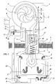
- Figure 1 is a schematic, partially cutaway view, of a device for burning gasified liquid fuels according to this invention.
- Referring to the drawing, one has marked a central control unit by 1, and electric transformer by 2, a centrifugal pump for supplying air as a comburant by 3, a pump for supplying liquid state fuel by 4.
Centrifugal pump 3 operates to supply air in the direction of arrow F. Such components are assembled in a structure not described and illustrated in detail, but within the skill of the man of the art. Such a structure is applied in a manner which is passing in the interior of acombustion chamber 5, to the wall of which in arefractory material 6 andmetal sheet 7 it is fixed by bolts schematized at 8. As schematized, the combustion chamber is surrounded by a hollow space orfumes box 20 for the exhaustion of fumes through aport 21, which also operates, in a rear part thereof, as a heat exchanger for an upper part of achamber 22 for drawing heated air, indicated by arrow A, for the combustion.Chamber 22 for drawing air is connected through apiping 23 tocentrifugal pump 3 for supplying air. - A
first piping 9 terminating in afirst nozzle 10 for ejecting atomized liquid state fuel is connected to supply pump 4.First piping 9 is endowed with afirst solenoid valve 11 for supplying fuel.First piping 9 is endowed with afirst solenoid valve 11 for the supply of the fuel. The ejected fuel, by virtue of the fine crumbling of the droplets, is ignited by anelectrode 12, which, connected to theelectric transformer 2, is excited under the control of central control unit 1. A first burner stage is so realized, which develops a priming flame in anignition zone 16 ofcombustion chamber 5. A second burner stage is formed of asecond piping 13 connected with pump 4 for supplying the fuel and endowed with asecond solenoid valve 14 for supplying the fuel at a steady state.Second piping 13 has agasification tract 15, formed as a pipe coil, which passes in theignition zone 16 ofcombustion chamber 5. Asignition zone 16 is heated by the priming flame, ingasification tract 15 ofsecond piping 13, one has the transformation of the fuel, which passes inside it, from the liquid state to the aeriform state.Second piping 13 terminates in adistribution passage 17, preferably cylindrical, to be distributed in an aeriform state inignition zone 16. A combustion chamber is formed therein, caused by the priming flame of the first burner. Thereafter, the priming flame is cut out controlled by central control unit 1. Aphotoelectric cell 18 for controlling the flame is connected with central control unit 1. As soon asphotoelectric cell 18 sees the flame in a steady state, it sends a signal of consent to regular operation to central control unit 1. These interactions are schematically indicated by arrows without reference numbers. The burner in its steady state continues the regular operation, tillphotoelectric cell 18 sees the flame burning. The flame in the steady state frees fumes schematically indicated by lines with arrows in succession, marked with f. - It is clear that
gasification tract 15 is to be realized in a material fit for withstanding the temperatures of the flame in the steady state of the second stage of the burner, which it is subjected to when the priming flame is cut out and only continues the combustion of the fuel coming out of the passageway for the distribution of the fuel in aeriform phase. - Suitably, a
governor 19 of flow of fuel toburner 17 is envisaged in the second piping.Governor 19 of the flow of fuel, which serves to adjust the flame at the steady state, can be realized under the form of a calibrated-hole plate, interposed in the fuel flow. - As regards the supply of air,
centrifugal pump 3 for supplying air as a comburant draws air for combustion in an upper part ofchamber 22 for drawing air. In this way, the supply air is heated at the expense of the exhaust fumes. So, the temperature can even be increased of the combustion chamber, achieving an optimum combustion, substantially devoid of unburnt particles. The environmental pollution is also reduced in such a way. - It should be apparent that the gasification tract could be externally endowed with other means for heating the fuel which passes inside it, such as for instance an electric resistance, which cooperates to the gasification of the fuel under the control of the central control unit.
- The device according to the present invention can be applied to normal boilers which burn liquid fuels, but also to the combustion in other fields, such as turbine aeronautical motors and internal combustion motors.
- Though not being part of the present invention, the fact is to be taken into account that in combustion motors having traditional carburetion, the position of the chamber having float and metering rod is to be modified to reduce the excessive inflow of liquid fuel. After the chamber having float and metering rod, positioned downstream of the pump for supplying the fuel, the pipe coil is foreseen of the device according to this invention, coiled around one of the pipes for exhausting fumes. In this way the liquid fuel is allowed to pass to the aeriform state and to arrive in this state into the combustion chamber of the motor. It is apparent that in this way the environmental pollution is lowered, whilst the fuel consumption is reduced.
Claims (7)
- Device for burning gasified liquid fuels, which includes a central control unit (1), an electric transformer (2), a centrifugal pump (3) for supplying air as a comburant, a pump (4) for supplying a liquid state fuel, and, moreover, in communication with a combustion chamber (5):a first burner stage, having a first piping (9) and a first nozzle (10) for ejecting the fuel in an atomized liquid state, the first piping (9) being connected to the pump (4) for supplying the fuel and endowed with a first solenoid valve (11) for supplying the priming fuel, the ejected fuel being ignited by an electrode (12) excited by the electric transformer under the control of the central control unit (1), the first burner stage developing a priming flame in a ignition zone (16) of the combustion chamber (5);a second burner stage, having a second piping (13) connected to the pump (4) for supplying the fuel and endowed with a second solenoid valve (14) for the steady-state supply of the fuel, the second piping (13) having a gasification tract (15) passing in said ignition zone (16) such as to allow the transformation of the fuel, which passes inside it, from the liquid state to the aeriform state and terminating in a distribution passageway (17) to be distributed in the aeriform state in said ignition zone (16), to form a combustion flame caused by said priming flame of the first burner, which is cut out after the ignition of the second burner stage.
- Device according to Claim 1, characterized in that said gasification tract (15) is formed as a pipe coil.
- Device according to Claim 1, characterized in that it also includes a photoelectric cell (18) for controlling the flame, connected to said central control unit (1).
- Device according to Claim 1, characterized in that it also includes a governor (19) of the flow of the fuel on said second piping (13).
- Device according to Claim 4, characterized in that said governor (19) of the flow of fuel is a calibrated-hole plate interposed to the flow of fuel.
- Device according to Claim 1, characterized in that said centrifugal pump (3) for supplying air as a comburant draws air for the combustion in an upper part of a drawing chamber (22) in heat exchange with the rear part of a fumes box (20).
- Device according to Claim 1, characterized in that said gasification tract is externally endowed with an electric resistance, which under the control of the central control unit cooperates in the gasification of the fuel.
Applications Claiming Priority (1)
| Application Number | Priority Date | Filing Date | Title |
|---|---|---|---|
| IT000260A ITRM20050260A1 (en) | 2005-05-25 | 2005-05-25 | DEVICE FOR BURNING LIQUID LIQUID FUELS. |
Publications (1)
| Publication Number | Publication Date |
|---|---|
| EP1731835A1 true EP1731835A1 (en) | 2006-12-13 |
Family
ID=37189033
Family Applications (1)
| Application Number | Title | Priority Date | Filing Date |
|---|---|---|---|
| EP06425339A Withdrawn EP1731835A1 (en) | 2005-05-25 | 2006-05-19 | Device for burning gasified liquid fuels |
Country Status (3)
| Country | Link |
|---|---|
| US (1) | US20060266350A1 (en) |
| EP (1) | EP1731835A1 (en) |
| IT (1) | ITRM20050260A1 (en) |
Families Citing this family (4)
| Publication number | Priority date | Publication date | Assignee | Title |
|---|---|---|---|---|
| CN103471096B (en) * | 2012-06-08 | 2016-04-20 | 佛山市源威科技开发有限公司 | A kind of biological alcohol oil combustion device |
| CN103982895B (en) * | 2014-05-23 | 2016-08-24 | 山西圣火伟业科技有限公司 | Alcohol-based fuel boiler vapourizing unit |
| CN110375295B (en) * | 2019-07-29 | 2021-03-02 | 中润海精密科技有限公司 | A working method of gasification combustion of a liquid fuel burner |
| CN110671698B (en) * | 2019-11-20 | 2025-04-25 | 郑州大学 | Alcohol-based fuel burner |
Citations (5)
| Publication number | Priority date | Publication date | Assignee | Title |
|---|---|---|---|---|
| DE2453539A1 (en) * | 1974-11-12 | 1976-05-13 | Anton Lurz | Open air ground heating system - has evaporator oil burner with burner pipe extended into heat conduction pipe |
| US4332547A (en) * | 1979-10-01 | 1982-06-01 | Macdonald Jr James D | Thrust augmenter ejector combustion device |
| EP0413214A2 (en) * | 1989-08-17 | 1991-02-20 | Alfred Kärcher GmbH & Co. | Pressurized vaporising burner, particularly for field ranges |
| US5002481A (en) * | 1986-08-08 | 1991-03-26 | Forschungszentrum Julich Gmbh | Apparatus for generating a combustible gaseous mixture |
| US5474442A (en) * | 1989-08-21 | 1995-12-12 | Advanced Mechanical Technology, Inc. | Vaporizing diesel burner |
Family Cites Families (2)
| Publication number | Priority date | Publication date | Assignee | Title |
|---|---|---|---|---|
| JPS5123342B2 (en) * | 1972-07-31 | 1976-07-16 | ||
| US4438705A (en) * | 1981-03-27 | 1984-03-27 | Basic J N Sen | Incinerator with two reburn stages, and, optionally, heat recovery |
-
2005
- 2005-05-25 IT IT000260A patent/ITRM20050260A1/en unknown
-
2006
- 2006-05-19 EP EP06425339A patent/EP1731835A1/en not_active Withdrawn
- 2006-05-25 US US11/441,382 patent/US20060266350A1/en not_active Abandoned
Patent Citations (5)
| Publication number | Priority date | Publication date | Assignee | Title |
|---|---|---|---|---|
| DE2453539A1 (en) * | 1974-11-12 | 1976-05-13 | Anton Lurz | Open air ground heating system - has evaporator oil burner with burner pipe extended into heat conduction pipe |
| US4332547A (en) * | 1979-10-01 | 1982-06-01 | Macdonald Jr James D | Thrust augmenter ejector combustion device |
| US5002481A (en) * | 1986-08-08 | 1991-03-26 | Forschungszentrum Julich Gmbh | Apparatus for generating a combustible gaseous mixture |
| EP0413214A2 (en) * | 1989-08-17 | 1991-02-20 | Alfred Kärcher GmbH & Co. | Pressurized vaporising burner, particularly for field ranges |
| US5474442A (en) * | 1989-08-21 | 1995-12-12 | Advanced Mechanical Technology, Inc. | Vaporizing diesel burner |
Also Published As
| Publication number | Publication date |
|---|---|
| ITRM20050260A1 (en) | 2005-08-24 |
| US20060266350A1 (en) | 2006-11-30 |
Similar Documents
| Publication | Publication Date | Title |
|---|---|---|
| CA1297397C (en) | Burner | |
| US7225998B2 (en) | Apparatus and method for preparing and delivering fuel | |
| US7481048B2 (en) | Regeneration assembly | |
| EP1936296B1 (en) | A heating appliance | |
| AU2009270341B2 (en) | Micro-pilot for gas appliance | |
| CN102353054A (en) | Gas burner capable of adjusting premix | |
| CN101688664B (en) | Method for burning liquid fuel | |
| CN110594743B (en) | Mixed fuel burner for burning low-heat-value waste gas by using high-heat-value waste liquid | |
| US20060266350A1 (en) | Device for burning gasified liquid fuels | |
| CN101178175A (en) | Lean oil heat intensified firing actuating apparatus of pulverized coal boiler | |
| US20050079458A1 (en) | Heater with an atomizer nozzle | |
| CN101769599B (en) | Negative-pressure infrared combusting device | |
| JPH04227408A (en) | Method of operating liquid-fuel supply type burner | |
| CN110260367B (en) | An alcohol-based gasification wall-mounted boiler | |
| CN111765634A (en) | Novel gas and liquid combined heating boiler and ignition method thereof | |
| CN105090950A (en) | Pre-evaporation self-turbulence fuel combustion machine | |
| KR100840539B1 (en) | Liquid fuel burners for easy ignition and combustion | |
| CN101413660B (en) | Heavy oil and low-oil-consumption ignition coal powder combustor | |
| CN201826984U (en) | Fuel heater using fuel gas fold-back double-side heaters and exchangers | |
| CN213178319U (en) | Ignition primary air combustion heating device of coal-fired boiler of power station | |
| JP2010196907A (en) | Combustion device | |
| CN102032591A (en) | Pulverized coal ignition system and control method thereof | |
| JP3685131B2 (en) | Combustion equipment | |
| KR200176905Y1 (en) | A hot wind device using a water and oil as a fuel | |
| EP3438531B1 (en) | Coal nozzle with a flow constriction |
Legal Events
| Date | Code | Title | Description |
|---|---|---|---|
| PUAI | Public reference made under article 153(3) epc to a published international application that has entered the european phase |
Free format text: ORIGINAL CODE: 0009012 |
|
| AK | Designated contracting states |
Kind code of ref document: A1 Designated state(s): AT BE BG CH CY CZ DE DK EE ES FI FR GB GR HU IE IS IT LI LT LU LV MC NL PL PT RO SE SI SK TR |
|
| AX | Request for extension of the european patent |
Extension state: AL BA HR MK YU |
|
| AKX | Designation fees paid | ||
| REG | Reference to a national code |
Ref country code: DE Ref legal event code: 8566 |
|
| STAA | Information on the status of an ep patent application or granted ep patent |
Free format text: STATUS: THE APPLICATION IS DEEMED TO BE WITHDRAWN |
|
| 18D | Application deemed to be withdrawn |
Effective date: 20070614 |