EP1731765A2 - External gear pump for a propeller drivable in both directions - Google Patents
External gear pump for a propeller drivable in both directions Download PDFInfo
- Publication number
- EP1731765A2 EP1731765A2 EP06252908A EP06252908A EP1731765A2 EP 1731765 A2 EP1731765 A2 EP 1731765A2 EP 06252908 A EP06252908 A EP 06252908A EP 06252908 A EP06252908 A EP 06252908A EP 1731765 A2 EP1731765 A2 EP 1731765A2
- Authority
- EP
- European Patent Office
- Prior art keywords
- pump
- gear
- propeller
- female spline
- recited
- Prior art date
- Legal status (The legal status is an assumption and is not a legal conclusion. Google has not performed a legal analysis and makes no representation as to the accuracy of the status listed.)
- Granted
Links
Images


Classifications
-
- F—MECHANICAL ENGINEERING; LIGHTING; HEATING; WEAPONS; BLASTING
- F04—POSITIVE - DISPLACEMENT MACHINES FOR LIQUIDS; PUMPS FOR LIQUIDS OR ELASTIC FLUIDS
- F04C—ROTARY-PISTON, OR OSCILLATING-PISTON, POSITIVE-DISPLACEMENT MACHINES FOR LIQUIDS; ROTARY-PISTON, OR OSCILLATING-PISTON, POSITIVE-DISPLACEMENT PUMPS
- F04C15/00—Component parts, details or accessories of machines, pumps or pumping installations, not provided for in groups F04C2/00 - F04C14/00
- F04C15/0057—Driving elements, brakes, couplings, transmission specially adapted for machines or pumps
- F04C15/0061—Means for transmitting movement from the prime mover to driven parts of the pump, e.g. clutches, couplings, transmissions
- F04C15/0073—Couplings between rotors and input or output shafts acting by interengaging or mating parts, i.e. positive coupling of rotor and shaft
-
- F—MECHANICAL ENGINEERING; LIGHTING; HEATING; WEAPONS; BLASTING
- F04—POSITIVE - DISPLACEMENT MACHINES FOR LIQUIDS; PUMPS FOR LIQUIDS OR ELASTIC FLUIDS
- F04C—ROTARY-PISTON, OR OSCILLATING-PISTON, POSITIVE-DISPLACEMENT MACHINES FOR LIQUIDS; ROTARY-PISTON, OR OSCILLATING-PISTON, POSITIVE-DISPLACEMENT PUMPS
- F04C14/00—Control of, monitoring of, or safety arrangements for, machines, pumps or pumping installations
- F04C14/04—Control of, monitoring of, or safety arrangements for, machines, pumps or pumping installations specially adapted for reversible machines or pumps
-
- F—MECHANICAL ENGINEERING; LIGHTING; HEATING; WEAPONS; BLASTING
- F04—POSITIVE - DISPLACEMENT MACHINES FOR LIQUIDS; PUMPS FOR LIQUIDS OR ELASTIC FLUIDS
- F04C—ROTARY-PISTON, OR OSCILLATING-PISTON, POSITIVE-DISPLACEMENT MACHINES FOR LIQUIDS; ROTARY-PISTON, OR OSCILLATING-PISTON, POSITIVE-DISPLACEMENT PUMPS
- F04C14/00—Control of, monitoring of, or safety arrangements for, machines, pumps or pumping installations
- F04C14/24—Control of, monitoring of, or safety arrangements for, machines, pumps or pumping installations characterised by using valves controlling pressure or flow rate, e.g. discharge valves or unloading valves
-
- F—MECHANICAL ENGINEERING; LIGHTING; HEATING; WEAPONS; BLASTING
- F04—POSITIVE - DISPLACEMENT MACHINES FOR LIQUIDS; PUMPS FOR LIQUIDS OR ELASTIC FLUIDS
- F04C—ROTARY-PISTON, OR OSCILLATING-PISTON, POSITIVE-DISPLACEMENT MACHINES FOR LIQUIDS; ROTARY-PISTON, OR OSCILLATING-PISTON, POSITIVE-DISPLACEMENT PUMPS
- F04C15/00—Component parts, details or accessories of machines, pumps or pumping installations, not provided for in groups F04C2/00 - F04C14/00
- F04C15/0057—Driving elements, brakes, couplings, transmission specially adapted for machines or pumps
- F04C15/0076—Fixing rotors on shafts, e.g. by clamping together hub and shaft
-
- F—MECHANICAL ENGINEERING; LIGHTING; HEATING; WEAPONS; BLASTING
- F04—POSITIVE - DISPLACEMENT MACHINES FOR LIQUIDS; PUMPS FOR LIQUIDS OR ELASTIC FLUIDS
- F04C—ROTARY-PISTON, OR OSCILLATING-PISTON, POSITIVE-DISPLACEMENT MACHINES FOR LIQUIDS; ROTARY-PISTON, OR OSCILLATING-PISTON, POSITIVE-DISPLACEMENT PUMPS
- F04C15/00—Component parts, details or accessories of machines, pumps or pumping installations, not provided for in groups F04C2/00 - F04C14/00
- F04C15/0057—Driving elements, brakes, couplings, transmission specially adapted for machines or pumps
- F04C15/008—Prime movers
-
- F—MECHANICAL ENGINEERING; LIGHTING; HEATING; WEAPONS; BLASTING
- F04—POSITIVE - DISPLACEMENT MACHINES FOR LIQUIDS; PUMPS FOR LIQUIDS OR ELASTIC FLUIDS
- F04C—ROTARY-PISTON, OR OSCILLATING-PISTON, POSITIVE-DISPLACEMENT MACHINES FOR LIQUIDS; ROTARY-PISTON, OR OSCILLATING-PISTON, POSITIVE-DISPLACEMENT PUMPS
- F04C2/00—Rotary-piston machines or pumps
- F04C2/08—Rotary-piston machines or pumps of intermeshing-engagement type, i.e. with engagement of co-operating members similar to that of toothed gearing
- F04C2/12—Rotary-piston machines or pumps of intermeshing-engagement type, i.e. with engagement of co-operating members similar to that of toothed gearing of other than internal-axis type
- F04C2/14—Rotary-piston machines or pumps of intermeshing-engagement type, i.e. with engagement of co-operating members similar to that of toothed gearing of other than internal-axis type with toothed rotary pistons
- F04C2/18—Rotary-piston machines or pumps of intermeshing-engagement type, i.e. with engagement of co-operating members similar to that of toothed gearing of other than internal-axis type with toothed rotary pistons with similar tooth forms
Definitions
- the present invention relates to a pump system, and more particularly to a pump system which may be interchangeably utilized for either a clockwise or counterclockwise propeller shaft rotation.
- Multi-engine propeller aircraft utilize pump systems which are driven by a propeller system gearbox.
- a pump system is mounted to a bulkhead within an engine nacelle of each engine to locate the main pump in proximity to the propeller system and associated gearbox.
- the propeller on adjacent engines typically rotates in opposite direction to counteract torque. That is, the propeller system of engine one rotates clockwise, the propeller system of engine two rotates counterclockwise, the propeller system of engine three rotates clockwise, and the propeller system of engine four rotates counterclockwise.
- Conventional pump systems include a male drive shaft that extends from the pump system. Such conventional pump systems are designed to be driven from either end by switching the shaft. That is, a mounting structure is located on one end of the pump and a relatively significant blanking plate is bolted to the unused end to close the unused end of the pump against full pump pressure. This permits any single pump to accommodate either a clockwise or counterclockwise driven propeller system.
- a pump system includes an inlet port, a discharge port, a drive aperture and a drain aperture.
- the drive aperture and the drain aperture are interchangeable such that the pump system may be utilized on either a clockwise or counterclockwise driven propeller.
- a gearbox driven male pump drive shaft is mounted into either aperture such that the aperture which receives the drive shaft becomes the drive aperture while the other aperture becomes the drain aperture.
- a first pump gear is the driver gear in meshing engagement with a second pump gear which is the driven gear.
- the pump gears each include external gears in meshing engagement which communicate the fluid around the outside of the gears to provide the fluid pumping action from the inlet port to the discharge port. Fluid which is not communicated to the discharge port eventually collects within the second pump gear and is communicated to a gearbox drain through the drain aperture.
- the pump system may accommodate either a clockwise or counterclockwise propeller gearbox.
- the present invention therefore provides a lightweight engine driven pump system which accommodates either a clockwise or counterclockwise propeller shaft rotation.
- Figure 1 illustrates a general schematic rear view of a multi-engine aircraft 10.
- the aircraft 10 includes a multiple of engines 12 each mounted to an aircraft wing 14.
- Each engine 12 is typically contained within an engine nacelle 16 having a bulkhead 18 through which passes a propeller shaft 20 to drive a propeller system 22 about an axis of rotation A.
- a pump system 24 (Figure 2) is mounted to each bulkhead 18 within the nacelle 16 of each engine 12.
- the pump system 24 is driven by a propeller gearbox 26 (illustrated schematically).
- the propeller system 22 on adjacent engines 12 typically rotate in opposite direction (illustrated by arrow R) to counteract torque. That is, the propeller shaft 20a of engine one 12a rotates clockwise, the propeller shaft 20b of engine two 12b rotates counterclockwise, the propeller shaft 20c engine three 12c rotates clockwise and the propeller shaft 20d of engine four 12d rotates counterclockwise as respectively driven by the gearbox 26.
- each associated pump system 24 be driven in a direction commensurate therewith.
- a mounting pad 27 is attached to each bulkhead 18 to mount the pump system 24 such that a pump drive shaft 28 rotates in a rotational direction (illustrated schematically by arrow r) relative to the propeller shaft 20 rotational direction R.
- the pump drive shaft 28 is preferably a male splined shaft.
- the pump shaft 28 rotates opposite the propeller shaft 20, however, other rotational schemes are also usable with the present invention.
- the male pump drive shaft 28 extends through the mounting pad 27 and is driven by the propeller gearbox 26 to drive the pump system 24.
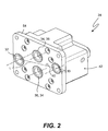
- the pump system 24 includes an inlet port 30, a discharge port 32, a drive aperture 34 and a drain aperture 36 ( Figure 2).
- the drive aperture 34 and the drain aperture 36 are interchangeable such that the pump system 24 may be utilized on either a clockwise or counterclockwise driven propeller. That is, the male pump drive shaft 28 is mounted into either aperture 34, 36. Whichever aperture 34, 36 the drive shaft 28 is installed into becomes the drive aperture 34 while the other aperture 36, 34 becomes the drain aperture 36.
- a locator pin 38 extends from the mounting pad 27 and is received into a locating aperture 40 formed into a seal plate 54 of pump housing 42 ( Figure 2).
- the locating pin 38 is in opposite positions on the mounting pad 27 depending upon whether the propeller system is clockwise or counterclockwise driven to assure proper mounting of the pump system 24.
- the locating aperture 40 is in only a single position on the pump system 24 ( Figure 2) to assure that fluid is pumped from the inlet port 30 to the discharge port 32 irrespective of which handed propeller gearbox the pump system 24 is mounted to.
- the inlet port 30 and the discharge port 32 are preferably located opposite each other and are spaced generally horizontally relative the vertically mounted apertures 34, 36. Such arrangement permits the drain aperture 36 to always be at the lowest point when the pump system 24 is mounted to the aircraft ( Figure 1). It should be understood that relative positional terms such as “forward,” “aft,” “upper,” “lower,” “above,” “below,” “horizontal,” “vertical,” and the like are with reference to the normal operational attitude of the vehicle and should not be considered otherwise limiting.
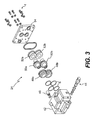
- the pump system 24 generally includes the pump housing 42, a relief valve assembly 44, a discharge check valve assembly 46, a first and second floating bearing 48a, 48b, a first and second pump gear 50a, 50b, a first and second fixed bearing 52a, 52b and a seal plate 54.
- a multitude of seals S assure a fluid seal between the rotating components when the seal plate 54 is fastened to the pump housing 42 by a multitude of fasteners f.
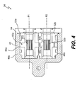
- the first pump gear 50a, the first floating bearing 48a and the first fixed bearing 52a defines a gear system along a first axis of rotation P 1 .
- the second pump gear 50b, the second floating bearing 48b and the second fixed bearing 52b defines a gear system along a second axis of rotation P 2 .
- the axes of rotation are P 1 and P 2 are parallel and generally transverse to a line L drawing between the inlet port 30 and discharge port 32 ( Figure 2).
- the first and second pump gear 50a, 50b each include an internal female spline 54a, 54b and an external gear 56a, 56b.
- the internal female spline 54a, 54b are equivalent and splined to receive the drive shaft 28 (Figure 5).
- the drive shaft 28 extends from the propeller gearbox 26 ( Figure 5) and is pressed into the appropriate internal female spline 54a, 54b depending upon whether the gearbox is of clockwise or counterclockwise rotation. Preferably, such installation may be accomplished at a field level environment.
- Either internal female spline 54a, 54b interchangeably receive the drive shaft 28 such that when the first internal female spline 54a receives the drive shaft 28, the first pump gear 50a is the driver gear, the first internal female spline 54a becomes the drive aperture 34, and the second internal female spline 54b becomes the drain aperture 36.
- the second internal female spline 54b receives the drive shaft 28
- the second pump gear 50b is the driver gear
- the second internal female spline 54b becomes the drive aperture 34
- the first internal female spline 54a becomes the drain aperture 36.
- the first pump gear 50a is the driver gear in meshing engagement with the second pump gear 50b which is the driven gear.
- the external gears 56a, 56b communicate the fluid around the outside of the gears 50a, 50b to provide the fluid pumping action from the inlet port 30 to the discharge port 32.
- the gear mesh operates as a seal. Fluid which is not communicated to the discharge port 32 eventually collects within and around the second pump gear 50b and is communicated to a gearbox drain through the internal female spline 54a and the drain aperture 36.
Landscapes
- Engineering & Computer Science (AREA)
- Mechanical Engineering (AREA)
- General Engineering & Computer Science (AREA)
- Rotary Pumps (AREA)
- Details And Applications Of Rotary Liquid Pumps (AREA)
Abstract
Description
- The present invention relates to a pump system, and more particularly to a pump system which may be interchangeably utilized for either a clockwise or counterclockwise propeller shaft rotation.
- Multi-engine propeller aircraft utilize pump systems which are driven by a propeller system gearbox. Typically, a pump system is mounted to a bulkhead within an engine nacelle of each engine to locate the main pump in proximity to the propeller system and associated gearbox. On multi-engine propeller aircraft, the propeller on adjacent engines typically rotates in opposite direction to counteract torque. That is, the propeller system of engine one rotates clockwise, the propeller system of engine two rotates counterclockwise, the propeller system of engine three rotates clockwise, and the propeller system of engine four rotates counterclockwise. Although an advantage from a propulsion perspective, such alternating rotations complicate pump installations as the engine gearboxes are also rotating in opposite directions. The associated pump drive systems must accommodate these specific rotations.
- Conventional pump systems include a male drive shaft that extends from the pump system. Such conventional pump systems are designed to be driven from either end by switching the shaft. That is, a mounting structure is located on one end of the pump and a relatively significant blanking plate is bolted to the unused end to close the unused end of the pump against full pump pressure. This permits any single pump to accommodate either a clockwise or counterclockwise driven propeller system.
- Disadvantageously, such conventional pump systems require that a clockwise mounting plate, a counterclockwise mounting plate and blanking plate be carried on the pump system at all times which increases system weight. The male drive shaft must also be removed and replaced to the opposite side to change the pump system to an opposite propeller rotation position. Such changeover requires disassembly of the pump at a significant depot level maintenance facilities which may increase aircraft downtime. The changeover to assure proper drive direction is a relatively complicated procedure which may further complicates maintenance time and expense.
- Accordingly, it is desirable to provide a lightweight engine driven pump system which accommodates either a clockwise or counterclockwise propeller shaft rotation.
- A pump system according to an embodiment of the present invention includes an inlet port, a discharge port, a drive aperture and a drain aperture. The drive aperture and the drain aperture are interchangeable such that the pump system may be utilized on either a clockwise or counterclockwise driven propeller. A gearbox driven male pump drive shaft is mounted into either aperture such that the aperture which receives the drive shaft becomes the drive aperture while the other aperture becomes the drain aperture.
- A first pump gear is the driver gear in meshing engagement with a second pump gear which is the driven gear. The pump gears each include external gears in meshing engagement which communicate the fluid around the outside of the gears to provide the fluid pumping action from the inlet port to the discharge port. Fluid which is not communicated to the discharge port eventually collects within the second pump gear and is communicated to a gearbox drain through the drain aperture. As either pumping gear may become the driver gear by receiving the male drive shaft, the pump system may accommodate either a clockwise or counterclockwise propeller gearbox.
- The present invention therefore provides a lightweight engine driven pump system which accommodates either a clockwise or counterclockwise propeller shaft rotation.
- The various features and advantages of this invention will become apparent to those skilled in the art from the following detailed description of the currently preferred embodiment. The drawings that accompany the detailed description can be briefly described as follows:
- Figure 1 is a general rear schematic view of a multi-engine aircraft for use with the present invention;
- Figure 2 is a perspective view of a pump system of the present invention;
- Figure 3 is an exploded view of a pump system of the present invention;
- Figure 4 is a sectional view of the pump system taken along line 4-4 in Figure 2; and
- Figure 5 is a schematic view of fluid flow through the pump system of the present invention.
- Figure 1 illustrates a general schematic rear view of a
multi-engine aircraft 10. Theaircraft 10 includes a multiple of engines 12 each mounted to anaircraft wing 14. Each engine 12 is typically contained within anengine nacelle 16 having abulkhead 18 through which passes apropeller shaft 20 to drive apropeller system 22 about an axis of rotation A. - A pump system 24 (Figure 2) is mounted to each
bulkhead 18 within thenacelle 16 of each engine 12. Thepump system 24 is driven by a propeller gearbox 26 (illustrated schematically). On multi-engine prop aircraft, thepropeller system 22 on adjacent engines 12 typically rotate in opposite direction (illustrated by arrow R) to counteract torque. That is, thepropeller shaft 20a of engine one 12a rotates clockwise, thepropeller shaft 20b of engine two 12b rotates counterclockwise, thepropeller shaft 20c engine three 12c rotates clockwise and thepropeller shaft 20d of engine four 12d rotates counterclockwise as respectively driven by thegearbox 26. - Such an alternating propeller rotation scheme requires that each associated
pump system 24 be driven in a direction commensurate therewith. Amounting pad 27 is attached to eachbulkhead 18 to mount thepump system 24 such that apump drive shaft 28 rotates in a rotational direction (illustrated schematically by arrow r) relative to thepropeller shaft 20 rotational direction R. Thepump drive shaft 28 is preferably a male splined shaft. Typically, thepump shaft 28 rotates opposite thepropeller shaft 20, however, other rotational schemes are also usable with the present invention. The malepump drive shaft 28 extends through themounting pad 27 and is driven by thepropeller gearbox 26 to drive thepump system 24. - The
pump system 24 includes aninlet port 30, adischarge port 32, adrive aperture 34 and a drain aperture 36 (Figure 2). Notably, thedrive aperture 34 and thedrain aperture 36 are interchangeable such that thepump system 24 may be utilized on either a clockwise or counterclockwise driven propeller. That is, the malepump drive shaft 28 is mounted into eitheraperture aperture drive shaft 28 is installed into becomes thedrive aperture 34 while theother aperture drain aperture 36. - Preferably, a
locator pin 38 extends from themounting pad 27 and is received into a locatingaperture 40 formed into aseal plate 54 of pump housing 42 (Figure 2). Notably, the locatingpin 38 is in opposite positions on themounting pad 27 depending upon whether the propeller system is clockwise or counterclockwise driven to assure proper mounting of thepump system 24. The locatingaperture 40 is in only a single position on the pump system 24 (Figure 2) to assure that fluid is pumped from theinlet port 30 to thedischarge port 32 irrespective of which handed propeller gearbox thepump system 24 is mounted to. - The
inlet port 30 and thedischarge port 32 are preferably located opposite each other and are spaced generally horizontally relative the vertically mountedapertures drain aperture 36 to always be at the lowest point when thepump system 24 is mounted to the aircraft (Figure 1). It should be understood that relative positional terms such as "forward," "aft," "upper," "lower," "above," "below," "horizontal," "vertical," and the like are with reference to the normal operational attitude of the vehicle and should not be considered otherwise limiting. - Referring to Figure 3, the
pump system 24 generally includes thepump housing 42, arelief valve assembly 44, a dischargecheck valve assembly 46, a first and second floating bearing 48a, 48b, a first andsecond pump gear seal plate 54. A multitude of seals S assure a fluid seal between the rotating components when theseal plate 54 is fastened to thepump housing 42 by a multitude of fasteners f. - Referring to Figure 4, the
first pump gear 50a, the first floating bearing 48a and the first fixed bearing 52a defines a gear system along a first axis of rotation P1. Thesecond pump gear 50b, the second floating bearing 48b and the second fixed bearing 52b defines a gear system along a second axis of rotation P2. The axes of rotation are P1 and P2 are parallel and generally transverse to a line L drawing between theinlet port 30 and discharge port 32 (Figure 2). - The first and
second pump gear female spline external gear female spline drive shaft 28 extends from the propeller gearbox 26 (Figure 5) and is pressed into the appropriate internalfemale spline - Either internal
female spline drive shaft 28 such that when the first internalfemale spline 54a receives thedrive shaft 28, thefirst pump gear 50a is the driver gear, the first internalfemale spline 54a becomes thedrive aperture 34, and the second internalfemale spline 54b becomes thedrain aperture 36. Alternatively, when the second internalfemale spline 54b receives thedrive shaft 28, thesecond pump gear 50b is the driver gear, the second internalfemale spline 54b becomes thedrive aperture 34, and the first internalfemale spline 54a becomes thedrain aperture 36. - Referring to Figure 5, the
first pump gear 50a is the driver gear in meshing engagement with thesecond pump gear 50b which is the driven gear. Theexternal gears gears inlet port 30 to thedischarge port 32. The gear mesh operates as a seal. Fluid which is not communicated to thedischarge port 32 eventually collects within and around thesecond pump gear 50b and is communicated to a gearbox drain through the internalfemale spline 54a and thedrain aperture 36. - It should be understood that although a particular component arrangement is disclosed in the illustrated embodiment, other arrangements will benefit from the instant invention.
- Although particular step sequences are shown, described, and claimed, it should be understood that steps may be performed in any order, separated or combined unless otherwise indicated and will still benefit from the present invention.
- The foregoing description is exemplary rather than defined by the limitations within. Many modifications and variations of the present invention are possible in light of the above teachings. The preferred embodiments of this invention have been disclosed, however, one of ordinary skill in the art would recognize that certain modifications would come within the scope of this invention. It is, therefore, to be understood that within the scope of the appended claims, the invention may be practiced otherwise than as specifically described. For that reason the following claims should be studied to determine the true scope and content of this invention.
Claims (18)
- A pump system (24) comprising:a first gear system (50a); anda second gear system (50b) in meshing engagement with said first gear system to pump a fluid from a pump inlet (30) to a pump discharge (32) wherein one of said first gear system and said second gear system is in communication with a drain aperture (36).
- The pump system as recited in claim 1, further comprising a shaft (28) located through a drive aperture (34) and engageable with the other of said first gear system (50a) and said second gear system (50b).
- The pump system as recited in claim 1, wherein said first gear system (50a) includes a first external gear (56a) and a first internal female spline (54a) and said second gear system (50b) includes a second external gear (56b) and a second internal female spline (54b), said first external gear (56a) in meshing engagement with said second external gear (56b), said first internal female spline (54a) in communication with a drive aperture (34) and said second internal female spline (54b) in communication with said drain aperture (36).
- The pump system as recited in claim 3, wherein said first female spline (54a) communicates with a pump drain.
- The pump system as recited in claim 3 or 4, further comprising a male shaft receivable in the other of said first female spline (54a) and said second female spline (54b) not in communication with said drain aperture (36).
- The pump system as recited in claim 3, 4 or 5, wherein said first external gear (56a) is coaxial with said first internal female spline (54a) and said second external gear (56b) is coaxial with said second internal female spline (54b).
- The pump system as recited in any of claims 3 to 6, wherein said first external gear (56a) and said second external gear (56b) pump a fluid about an outer periphery thereof.
- The pump system as recited in any preceding claim, wherein said first gear system (50a) rotates about a first axis and said second gear system (50b) rotates about a second axis parallel to said first axis.
- The pump system as recited in claim 8, wherein a line connecting said pump inlet (30) and said pump discharge (32) is transverse to said first and second axes.
- The pump system as recited in any preceding claim, further comprising a pump mounting pad (27) having a locating feature (38) which extends therefrom, said locating feature (38) engageable with said pump system to orient said pump system relative a propeller rotational direction.
- A propeller system (10) comprising:a pump mounting pad (27) for a propeller system driven in a propeller rotational direction;a shaft (28) which extends though said pump mounting plate (27), said shaft (28) driven in a shaft rotational direction relative to the propeller rotational direction of the propeller system; anda pump system (24) mounted to said pump mounting pad (27), said pump system comprising:a first gear system (50a) having a first female spline (54a); anda second gear system (50b) in meshing engagement with said first gear system (50a) to pump a fluid from a pump inlet (30) to a pump discharge (32), said second gear system (50b) having a second female spline (54b), said shaft (28) receivable in one of said first female spline (54a) or said second female spline (54b) in response to the rotational direction of the propeller system, the other of said first female spline (54a) and said second female spline (54b) in communication with a drain aperture (36).
- The propeller system as recited in claim 11, wherein said pump mounting pad (27) includes a locating feature (38) which engages said pump system to rotationally orient said pump system such that said male shaft (28) is receivable in said one of said first female spline (54a) or said second female spline (54b) in response to the rotational direction of the propeller system.
- The propeller system as recited in claim 11 or 12, wherein said drain aperture (36) is located below said shaft (28) relative a rotational axis of the propeller system.
- A method of mounting a pump system (24) to either a clockwise or counterclockwise rotating drive system comprising the steps of:(1) driving a shaft (28) in a rotational direction related to a rotational direction of a rotating drive system;(2) engaging the shaft (28) with one of a first and second gear system (50a,50b) of a pump system (24) depending on the rotational direction of the rotational drive system, the first and second gear systems (50a,50b) in meshing engagement such that the first and second gear systems (50a,50b) pumps a fluid from a pump inlet (30) to a pump discharge (32).
- A method as recited in claim 14, wherein said step (1) further comprises:(a) driving the shaft (28) with a propeller gearbox (26).
- A method as recited in claim 14 or 15, wherein said step (2) further comprises:(a) engaging the shaft (28) with an internal spline engagement (54a,54b) of the one of the first and second gear systems (50a,50b).
- A method as recited in claim 14, 15 or 16, further comprising the steps of:(3) orienting the pump system (24) with respect to the rotational direction of the rotating system.
- A method as recited in any of claims 14 to 17, wherein said step (2) further comprises:(a) communicating the other of the first and second gear system (50a,50b) with a drain aperture (36).
Applications Claiming Priority (1)
| Application Number | Priority Date | Filing Date | Title |
|---|---|---|---|
| US11/146,813 US8092202B2 (en) | 2005-06-07 | 2005-06-07 | Propeller pump system for handed propeller applications |
Publications (3)
| Publication Number | Publication Date |
|---|---|
| EP1731765A2 true EP1731765A2 (en) | 2006-12-13 |
| EP1731765A3 EP1731765A3 (en) | 2010-05-05 |
| EP1731765B1 EP1731765B1 (en) | 2013-10-09 |
Family
ID=36813645
Family Applications (1)
| Application Number | Title | Priority Date | Filing Date |
|---|---|---|---|
| EP06252908.6A Active EP1731765B1 (en) | 2005-06-07 | 2006-06-06 | External gear pump for a propeller drivable in both directions |
Country Status (2)
| Country | Link |
|---|---|
| US (1) | US8092202B2 (en) |
| EP (1) | EP1731765B1 (en) |
Cited By (1)
| Publication number | Priority date | Publication date | Assignee | Title |
|---|---|---|---|---|
| EP1985859A3 (en) * | 2007-04-24 | 2016-09-28 | ABER- Embraiagens e Comandos Hidraulicos Antonio Bernardes, Lda. | Hydraulic pump system with integrated distributor valve |
Families Citing this family (4)
| Publication number | Priority date | Publication date | Assignee | Title |
|---|---|---|---|---|
| US9574558B2 (en) | 2014-03-14 | 2017-02-21 | Woodward, Inc. | High pressure gear pump with dual wall housing |
| US9975424B2 (en) | 2015-05-15 | 2018-05-22 | Cnh Industrial America Llc | Dropbox assembly for transmission of work vehicle |
| WO2017009994A1 (en) * | 2015-07-16 | 2017-01-19 | 株式会社Ihi | Triple gear pump and fluid supplying device |
| FR3098258B1 (en) * | 2019-07-03 | 2021-07-16 | Safran Aircraft Engines | Tilting gear pump for a turbomachine, which can be incorporated into an aircraft engine lubrication circuit |
Citations (2)
| Publication number | Priority date | Publication date | Assignee | Title |
|---|---|---|---|---|
| WO1981001315A1 (en) | 1979-10-30 | 1981-05-14 | Tyrone Hydraulics | Contaminant resistant gear pumps and motors |
| US20050022381A1 (en) | 2002-10-28 | 2005-02-03 | Soqi Kabushiki Kaisha | Method of making gear pump |
Family Cites Families (18)
| Publication number | Priority date | Publication date | Assignee | Title |
|---|---|---|---|---|
| US1687523A (en) * | 1926-02-15 | 1928-10-16 | Edwin G Staude | Fluid-pressure pump for power-propelled vehicle-controlling means |
| US2000500A (en) * | 1934-01-06 | 1935-05-07 | Turner Louis Joseph | Power transmitting mechanism |
| US2258077A (en) * | 1937-07-28 | 1941-10-07 | Robert S Taylor | Oiling system for gearing |
| GB526260A (en) | 1938-03-18 | 1940-09-13 | James Pontus Johnson | Improvements in or relating to gear pumps |
| US2606498A (en) * | 1946-10-28 | 1952-08-12 | Eureka Williams Corp | Pump unit |
| US2571377A (en) * | 1947-05-15 | 1951-10-16 | Prec Developments Co Ltd | Rotary displacement pump |
| US2665636A (en) * | 1949-11-19 | 1954-01-12 | Borg Warner | Reversible gear pump |
| US3076413A (en) * | 1959-12-29 | 1963-02-05 | Parker Hannifin Corp | High pressure aircraft gear pump |
| US3059584A (en) * | 1960-01-13 | 1962-10-23 | Sonic Eng Corp | Rotary pumps and compressors |
| US3286643A (en) * | 1963-10-14 | 1966-11-22 | Dowty Technical Dev Ltd | Gear pumps and motors |
| US3244110A (en) * | 1965-01-15 | 1966-04-05 | Planet Products Corp | Pump |
| FR2119294A5 (en) | 1970-12-24 | 1972-08-04 | Joyeux Jean Pierre | |
| IT1152206B (en) * | 1981-05-30 | 1986-12-31 | Rolls Royce | GEAR PUMPS |
| US6200117B1 (en) * | 1998-12-04 | 2001-03-13 | Antony Mark Brown | Rotary lobe pumps |
| US6979185B2 (en) * | 2000-08-01 | 2005-12-27 | Kaempe Staffan I | Bi-rotational pump/hydraulic actuator |
| US6716011B2 (en) * | 2001-06-14 | 2004-04-06 | Monarch Hydraulics, Inc. | Hydraulic pump utilizing floating shafts |
| JP4333422B2 (en) * | 2003-06-02 | 2009-09-16 | 株式会社島津製作所 | Gear pump or motor |
| US7124662B2 (en) * | 2004-01-30 | 2006-10-24 | Pratt & Whitney Canada Corp. | Reversible driving apparatus for PCU pumps |
-
2005
- 2005-06-07 US US11/146,813 patent/US8092202B2/en active Active
-
2006
- 2006-06-06 EP EP06252908.6A patent/EP1731765B1/en active Active
Patent Citations (2)
| Publication number | Priority date | Publication date | Assignee | Title |
|---|---|---|---|---|
| WO1981001315A1 (en) | 1979-10-30 | 1981-05-14 | Tyrone Hydraulics | Contaminant resistant gear pumps and motors |
| US20050022381A1 (en) | 2002-10-28 | 2005-02-03 | Soqi Kabushiki Kaisha | Method of making gear pump |
Cited By (1)
| Publication number | Priority date | Publication date | Assignee | Title |
|---|---|---|---|---|
| EP1985859A3 (en) * | 2007-04-24 | 2016-09-28 | ABER- Embraiagens e Comandos Hidraulicos Antonio Bernardes, Lda. | Hydraulic pump system with integrated distributor valve |
Also Published As
| Publication number | Publication date |
|---|---|
| US8092202B2 (en) | 2012-01-10 |
| US20060275117A1 (en) | 2006-12-07 |
| EP1731765A3 (en) | 2010-05-05 |
| EP1731765B1 (en) | 2013-10-09 |
Similar Documents
| Publication | Publication Date | Title |
|---|---|---|
| EP1918550B1 (en) | Lubrication of windmilling journal bearing | |
| US9481437B2 (en) | Outboard motor | |
| US9518687B2 (en) | Device for the blind coupling of fluidic, electrical or similar supplies, to a receiving control mechanism | |
| EP1731765B1 (en) | External gear pump for a propeller drivable in both directions | |
| US8079886B2 (en) | Cooling system for outboard motor | |
| US10112483B2 (en) | Hydraulic pump assembly with forward driveshaft clearance | |
| EP0543601B1 (en) | Rotary assemblies | |
| US9726272B2 (en) | Assembly for adjustably mounting a gear of a pump to a gear of a driver equipment | |
| US20090180827A1 (en) | Mounting Arrangement | |
| JP2009149186A (en) | Outboard motor | |
| JPS5996092A (en) | Double reversal propeller apparatus | |
| EP2439411B1 (en) | Pump assembly, in particular for helicopter lubrication | |
| US9708044B2 (en) | Outboard motor | |
| US12092107B2 (en) | Dual input pump assembly | |
| EP3339583B1 (en) | Distributed fan lubrication system | |
| CN109555602B (en) | Oil return system of transmission box | |
| US11391362B2 (en) | Oil pump receiving bore lip | |
| EP3945204A1 (en) | Oil standpipe assembly for servicing and oil level maintenance of a starter in a gas turbine engine | |
| US6679741B2 (en) | Propulsion system having means dedicated for driving accessories in a boat | |
| US8166927B2 (en) | Outboard motor | |
| US20200116213A1 (en) | Hydraulic pump for a hydraulic connection interface of a clutch mechanism | |
| US12491977B1 (en) | Gearcase assemblies for marine drives having torpedo plugs | |
| CN109630276B (en) | Transmission box body | |
| EP3070349A1 (en) | Variable coaxial shaft for hydraulic unit | |
| CN109578143B (en) | Transmission box oil pumping device |
Legal Events
| Date | Code | Title | Description |
|---|---|---|---|
| PUAI | Public reference made under article 153(3) epc to a published international application that has entered the european phase |
Free format text: ORIGINAL CODE: 0009012 |
|
| AK | Designated contracting states |
Kind code of ref document: A2 Designated state(s): AT BE BG CH CY CZ DE DK EE ES FI FR GB GR HU IE IS IT LI LT LU LV MC NL PL PT RO SE SI SK TR |
|
| AX | Request for extension of the european patent |
Extension state: AL BA HR MK YU |
|
| PUAL | Search report despatched |
Free format text: ORIGINAL CODE: 0009013 |
|
| AK | Designated contracting states |
Kind code of ref document: A3 Designated state(s): AT BE BG CH CY CZ DE DK EE ES FI FR GB GR HU IE IS IT LI LT LU LV MC NL PL PT RO SE SI SK TR |
|
| AX | Request for extension of the european patent |
Extension state: AL BA HR MK RS |
|
| RIC1 | Information provided on ipc code assigned before grant |
Ipc: B64C 11/38 20060101ALI20100326BHEP Ipc: F04C 2/18 20060101AFI20060829BHEP Ipc: F04C 15/00 20060101ALI20100326BHEP |
|
| 17P | Request for examination filed |
Effective date: 20101029 |
|
| 17Q | First examination report despatched |
Effective date: 20101206 |
|
| AKX | Designation fees paid |
Designated state(s): DE FR GB IT |
|
| GRAP | Despatch of communication of intention to grant a patent |
Free format text: ORIGINAL CODE: EPIDOSNIGR1 |
|
| GRAS | Grant fee paid |
Free format text: ORIGINAL CODE: EPIDOSNIGR3 |
|
| GRAA | (expected) grant |
Free format text: ORIGINAL CODE: 0009210 |
|
| AK | Designated contracting states |
Kind code of ref document: B1 Designated state(s): DE FR GB IT |
|
| REG | Reference to a national code |
Ref country code: GB Ref legal event code: FG4D |
|
| REG | Reference to a national code |
Ref country code: DE Ref legal event code: R096 Ref document number: 602006038759 Country of ref document: DE Effective date: 20131205 |
|
| REG | Reference to a national code |
Ref country code: DE Ref legal event code: R097 Ref document number: 602006038759 Country of ref document: DE |
|
| PLBE | No opposition filed within time limit |
Free format text: ORIGINAL CODE: 0009261 |
|
| STAA | Information on the status of an ep patent application or granted ep patent |
Free format text: STATUS: NO OPPOSITION FILED WITHIN TIME LIMIT |
|
| 26N | No opposition filed |
Effective date: 20140710 |
|
| REG | Reference to a national code |
Ref country code: DE Ref legal event code: R097 Ref document number: 602006038759 Country of ref document: DE Effective date: 20140710 |
|
| REG | Reference to a national code |
Ref country code: DE Ref legal event code: R119 Ref document number: 602006038759 Country of ref document: DE |
|
| REG | Reference to a national code |
Ref country code: DE Ref legal event code: R119 Ref document number: 602006038759 Country of ref document: DE Effective date: 20150101 |
|
| PG25 | Lapsed in a contracting state [announced via postgrant information from national office to epo] |
Ref country code: DE Free format text: LAPSE BECAUSE OF NON-PAYMENT OF DUE FEES Effective date: 20150101 Ref country code: IT Free format text: LAPSE BECAUSE OF NON-PAYMENT OF DUE FEES Effective date: 20140606 |
|
| REG | Reference to a national code |
Ref country code: FR Ref legal event code: PLFP Year of fee payment: 11 |
|
| REG | Reference to a national code |
Ref country code: FR Ref legal event code: PLFP Year of fee payment: 12 |
|
| REG | Reference to a national code |
Ref country code: FR Ref legal event code: PLFP Year of fee payment: 13 |
|
| P01 | Opt-out of the competence of the unified patent court (upc) registered |
Effective date: 20230522 |
|
| PGFP | Annual fee paid to national office [announced via postgrant information from national office to epo] |
Ref country code: GB Payment date: 20250520 Year of fee payment: 20 |
|
| PGFP | Annual fee paid to national office [announced via postgrant information from national office to epo] |
Ref country code: FR Payment date: 20250520 Year of fee payment: 20 |