EP1731763A2 - Displacement control valve of variable displacement compressor - Google Patents
Displacement control valve of variable displacement compressor Download PDFInfo
- Publication number
- EP1731763A2 EP1731763A2 EP06115175A EP06115175A EP1731763A2 EP 1731763 A2 EP1731763 A2 EP 1731763A2 EP 06115175 A EP06115175 A EP 06115175A EP 06115175 A EP06115175 A EP 06115175A EP 1731763 A2 EP1731763 A2 EP 1731763A2
- Authority
- EP
- European Patent Office
- Prior art keywords
- valve
- chamber
- valve body
- axis
- rod
- Prior art date
- Legal status (The legal status is an assumption and is not a legal conclusion. Google has not performed a legal analysis and makes no representation as to the accuracy of the status listed.)
- Granted
Links
Images


Classifications
-
- F—MECHANICAL ENGINEERING; LIGHTING; HEATING; WEAPONS; BLASTING
- F04—POSITIVE - DISPLACEMENT MACHINES FOR LIQUIDS; PUMPS FOR LIQUIDS OR ELASTIC FLUIDS
- F04B—POSITIVE-DISPLACEMENT MACHINES FOR LIQUIDS; PUMPS
- F04B27/00—Multi-cylinder pumps specially adapted for elastic fluids and characterised by number or arrangement of cylinders
- F04B27/08—Multi-cylinder pumps specially adapted for elastic fluids and characterised by number or arrangement of cylinders having cylinders coaxial with, or parallel or inclined to, main shaft axis
- F04B27/14—Control
- F04B27/16—Control of pumps with stationary cylinders
- F04B27/18—Control of pumps with stationary cylinders by varying the relative positions of a swash plate and a cylinder block
- F04B27/1804—Controlled by crankcase pressure
-
- F—MECHANICAL ENGINEERING; LIGHTING; HEATING; WEAPONS; BLASTING
- F04—POSITIVE - DISPLACEMENT MACHINES FOR LIQUIDS; PUMPS FOR LIQUIDS OR ELASTIC FLUIDS
- F04B—POSITIVE-DISPLACEMENT MACHINES FOR LIQUIDS; PUMPS
- F04B27/00—Multi-cylinder pumps specially adapted for elastic fluids and characterised by number or arrangement of cylinders
- F04B27/08—Multi-cylinder pumps specially adapted for elastic fluids and characterised by number or arrangement of cylinders having cylinders coaxial with, or parallel or inclined to, main shaft axis
- F04B27/10—Multi-cylinder pumps specially adapted for elastic fluids and characterised by number or arrangement of cylinders having cylinders coaxial with, or parallel or inclined to, main shaft axis having stationary cylinders
- F04B27/1009—Distribution members
- F04B27/1018—Cylindrical distribution members
-
- F—MECHANICAL ENGINEERING; LIGHTING; HEATING; WEAPONS; BLASTING
- F04—POSITIVE - DISPLACEMENT MACHINES FOR LIQUIDS; PUMPS FOR LIQUIDS OR ELASTIC FLUIDS
- F04B—POSITIVE-DISPLACEMENT MACHINES FOR LIQUIDS; PUMPS
- F04B27/00—Multi-cylinder pumps specially adapted for elastic fluids and characterised by number or arrangement of cylinders
- F04B27/08—Multi-cylinder pumps specially adapted for elastic fluids and characterised by number or arrangement of cylinders having cylinders coaxial with, or parallel or inclined to, main shaft axis
- F04B27/10—Multi-cylinder pumps specially adapted for elastic fluids and characterised by number or arrangement of cylinders having cylinders coaxial with, or parallel or inclined to, main shaft axis having stationary cylinders
- F04B27/1036—Component parts, details, e.g. sealings, lubrication
- F04B27/1081—Casings, housings
-
- F—MECHANICAL ENGINEERING; LIGHTING; HEATING; WEAPONS; BLASTING
- F04—POSITIVE - DISPLACEMENT MACHINES FOR LIQUIDS; PUMPS FOR LIQUIDS OR ELASTIC FLUIDS
- F04B—POSITIVE-DISPLACEMENT MACHINES FOR LIQUIDS; PUMPS
- F04B27/00—Multi-cylinder pumps specially adapted for elastic fluids and characterised by number or arrangement of cylinders
- F04B27/08—Multi-cylinder pumps specially adapted for elastic fluids and characterised by number or arrangement of cylinders having cylinders coaxial with, or parallel or inclined to, main shaft axis
- F04B27/14—Control
- F04B27/16—Control of pumps with stationary cylinders
- F04B27/18—Control of pumps with stationary cylinders by varying the relative positions of a swash plate and a cylinder block
- F04B27/1804—Controlled by crankcase pressure
- F04B2027/1809—Controlled pressure
- F04B2027/1813—Crankcase pressure
-
- F—MECHANICAL ENGINEERING; LIGHTING; HEATING; WEAPONS; BLASTING
- F04—POSITIVE - DISPLACEMENT MACHINES FOR LIQUIDS; PUMPS FOR LIQUIDS OR ELASTIC FLUIDS
- F04B—POSITIVE-DISPLACEMENT MACHINES FOR LIQUIDS; PUMPS
- F04B27/00—Multi-cylinder pumps specially adapted for elastic fluids and characterised by number or arrangement of cylinders
- F04B27/08—Multi-cylinder pumps specially adapted for elastic fluids and characterised by number or arrangement of cylinders having cylinders coaxial with, or parallel or inclined to, main shaft axis
- F04B27/14—Control
- F04B27/16—Control of pumps with stationary cylinders
- F04B27/18—Control of pumps with stationary cylinders by varying the relative positions of a swash plate and a cylinder block
- F04B27/1804—Controlled by crankcase pressure
- F04B2027/1822—Valve-controlled fluid connection
- F04B2027/1827—Valve-controlled fluid connection between crankcase and discharge chamber
-
- F—MECHANICAL ENGINEERING; LIGHTING; HEATING; WEAPONS; BLASTING
- F04—POSITIVE - DISPLACEMENT MACHINES FOR LIQUIDS; PUMPS FOR LIQUIDS OR ELASTIC FLUIDS
- F04B—POSITIVE-DISPLACEMENT MACHINES FOR LIQUIDS; PUMPS
- F04B27/00—Multi-cylinder pumps specially adapted for elastic fluids and characterised by number or arrangement of cylinders
- F04B27/08—Multi-cylinder pumps specially adapted for elastic fluids and characterised by number or arrangement of cylinders having cylinders coaxial with, or parallel or inclined to, main shaft axis
- F04B27/14—Control
- F04B27/16—Control of pumps with stationary cylinders
- F04B27/18—Control of pumps with stationary cylinders by varying the relative positions of a swash plate and a cylinder block
- F04B27/1804—Controlled by crankcase pressure
- F04B2027/184—Valve controlling parameter
- F04B2027/1845—Crankcase pressure
-
- F—MECHANICAL ENGINEERING; LIGHTING; HEATING; WEAPONS; BLASTING
- F04—POSITIVE - DISPLACEMENT MACHINES FOR LIQUIDS; PUMPS FOR LIQUIDS OR ELASTIC FLUIDS
- F04B—POSITIVE-DISPLACEMENT MACHINES FOR LIQUIDS; PUMPS
- F04B27/00—Multi-cylinder pumps specially adapted for elastic fluids and characterised by number or arrangement of cylinders
- F04B27/08—Multi-cylinder pumps specially adapted for elastic fluids and characterised by number or arrangement of cylinders having cylinders coaxial with, or parallel or inclined to, main shaft axis
- F04B27/14—Control
- F04B27/16—Control of pumps with stationary cylinders
- F04B27/18—Control of pumps with stationary cylinders by varying the relative positions of a swash plate and a cylinder block
- F04B27/1804—Controlled by crankcase pressure
- F04B2027/184—Valve controlling parameter
- F04B2027/1854—External parameters
-
- F—MECHANICAL ENGINEERING; LIGHTING; HEATING; WEAPONS; BLASTING
- F04—POSITIVE - DISPLACEMENT MACHINES FOR LIQUIDS; PUMPS FOR LIQUIDS OR ELASTIC FLUIDS
- F04B—POSITIVE-DISPLACEMENT MACHINES FOR LIQUIDS; PUMPS
- F04B27/00—Multi-cylinder pumps specially adapted for elastic fluids and characterised by number or arrangement of cylinders
- F04B27/08—Multi-cylinder pumps specially adapted for elastic fluids and characterised by number or arrangement of cylinders having cylinders coaxial with, or parallel or inclined to, main shaft axis
- F04B27/14—Control
- F04B27/16—Control of pumps with stationary cylinders
- F04B27/18—Control of pumps with stationary cylinders by varying the relative positions of a swash plate and a cylinder block
- F04B27/1804—Controlled by crankcase pressure
- F04B2027/184—Valve controlling parameter
- F04B2027/1859—Suction pressure
-
- F—MECHANICAL ENGINEERING; LIGHTING; HEATING; WEAPONS; BLASTING
- F05—INDEXING SCHEMES RELATING TO ENGINES OR PUMPS IN VARIOUS SUBCLASSES OF CLASSES F01-F04
- F05B—INDEXING SCHEME RELATING TO WIND, SPRING, WEIGHT, INERTIA OR LIKE MOTORS, TO MACHINES OR ENGINES FOR LIQUIDS COVERED BY SUBCLASSES F03B, F03D AND F03G
- F05B2210/00—Working fluid
- F05B2210/10—Kind or type
- F05B2210/12—Kind or type gaseous, i.e. compressible
-
- F—MECHANICAL ENGINEERING; LIGHTING; HEATING; WEAPONS; BLASTING
- F05—INDEXING SCHEMES RELATING TO ENGINES OR PUMPS IN VARIOUS SUBCLASSES OF CLASSES F01-F04
- F05B—INDEXING SCHEME RELATING TO WIND, SPRING, WEIGHT, INERTIA OR LIKE MOTORS, TO MACHINES OR ENGINES FOR LIQUIDS COVERED BY SUBCLASSES F03B, F03D AND F03G
- F05B2210/00—Working fluid
- F05B2210/10—Kind or type
- F05B2210/14—Refrigerants with particular properties, e.g. HFC-134a
-
- Y—GENERAL TAGGING OF NEW TECHNOLOGICAL DEVELOPMENTS; GENERAL TAGGING OF CROSS-SECTIONAL TECHNOLOGIES SPANNING OVER SEVERAL SECTIONS OF THE IPC; TECHNICAL SUBJECTS COVERED BY FORMER USPC CROSS-REFERENCE ART COLLECTIONS [XRACs] AND DIGESTS
- Y10—TECHNICAL SUBJECTS COVERED BY FORMER USPC
- Y10S—TECHNICAL SUBJECTS COVERED BY FORMER USPC CROSS-REFERENCE ART COLLECTIONS [XRACs] AND DIGESTS
- Y10S417/00—Pumps
Definitions
- the present invention relates to a displacement control valve which constitutes a refrigerant circulation path and is used in a variable displacement compressor capable of changing a refrigerant displacement on the basis of a pressure in a control pressure zone within the compressor.
- variable displacement compressor forms a part of the circulation path in which a refrigerant gas corresponding to a fluid circulates, for example, in an air conditioner for a vehicle.
- the variable displacement compressor is provided with a control pressure chamber (a control pressure zone), and a swash plate is arranged in the control pressure chamber in such a manner that a inclination thereof can be changed.
- the inclination of the swash plate is changed in correspondence to a pressure in the control pressure chamber.
- the pressure in the control pressure chamber becomes higher, and an inclination angle of the swash plate becomes smaller, a stroke of pistons becomes smaller, and a displacement of the refrigerant gas is reduced.
- the pressure in the control pressure chamber becomes lower, and the inclination angle of the swash plate becomes larger, the stroke of the pistons becomes larger, and the displacement of the refrigerant gas is increased.
- variable displacement compressor there are connected a gas passage for supplying the refrigerant gas to the control pressure chamber from the discharge pressure zone, and a displacement control valve for opening and closing the gas passage.
- the displacement control valve is provided with a solenoid portion, and a pressure sensing means for actuating a valve body in correspondence to the pressure of the refrigerant gas.
- the solenoid portion is provided with a tubular fixed iron core, and a movable iron core and a rod coupled to the movable iron core are inserted to the fixed iron core.
- the displacement control valve is provided with a valve chamber within a housing, and a valve body is arranged in the valve chamber so as to be capable of reciprocating.
- the valve chamber is provided with a guide portion for moving the valve body along an axis of the valve chamber.
- the valve body is fixed to an end portion in an opposite side to the movable iron core in the rod.
- the valve body reciprocates together with the rod.
- the valve portion of the valve body selectively contacts and separate from a valve seat of the valve chamber on the basis of a reciprocation of the valve body. Accordingly, a valve hole and the gas passage are selectively opened and closed so as to adjust a supply amount of the refrigerant gas from the discharge pressure zone to the control pressure chamber.
- a displacement control valve disclosed in Japanese Laid-Open Patent Publication No. 2003-322086 is structured such that no excessive pressure is applied to the pressure sensing means at a time when the valve body is opened, by introducing a pressure in a suction pressure zone into the valve body.
- a pressure in a suction pressure zone into the valve body.
- an open passage is formed within the rod and the valve body in such a manner as to communicate with the suction pressure zone.
- one aspect of the present invention provides a displacement control valve that forms a part of a circulation path of a refrigerant gas and is used in a variable displacement compressor capable of changing a displacement of the refrigerant gas.
- the displacement control valve includes a valve chamber, a valve body, a rod, actuation means, a flow passage, and a guide portion.
- the valve chamber is provided within the displacement control valve and forms a part of a gas passage in which the refrigerant gas flows.
- the valve chamber has an axis and a valve seat.
- the valve body is movably arranged within the valve chamber.
- the valve body has a valve portion.
- the valve portion selectively contacts and separates from the valve seat of the valve chamber, whereby the gas passage is selectively opened and closed.
- the rod is integrally moving with the valve body.
- the actuation means actuates the rod for positioning the valve body within the valve chamber.
- the flow passage is provided within the rod and the valve body.
- the refrigerant gas flows through the flow passage.
- the guide portion moves the valve body along an axis of the valve chamber. At least one of the valve portion and the valve seat is formed along a surface of an imaginary sphere in which an intermediate point of a length of the guide portion along the axis of the valve chamber is set to a center on the axis, and a distance from the intermediate point to the contact point between the valve seat and the valve portion is set to a radius.
- the seal structure includes a valve chamber, a valve body, a rod, actuation means, a flow passage, and a guide portion.
- the valve chamber is provided within the valve apparatus and forms a flow path in which a fluid flows.
- the valve chamber has an axis and a valve seat.
- the valve body is movably arranged within the valve chamber.
- the valve body has a valve portion. The valve portion selectively contacts and separates from the valve seat of the valve chamber, whereby the flow path is selectively opened and closed.
- the rod integrally moves with the valve body.
- the actuation means actuates the rod for positioning the valve body within the valve chamber.
- the flow passage is provided within the rod and the valve body. The fluid flows through the flow passage.
- the guide portion moves the valve body along an axis of the valve chamber.
- At least one of the valve portion and the valve seat is formed along a surface of an imaginary sphere in which an intermediate point of a length of the guide portion along the axis of the valve chamber is set to a center on the axis, and a distance from the intermediate point to the contact point between the valve seat and the valve portion is set to a radius.
- a variable displacement compressor 10 is provided with a cylinder block 11, and a front housing member 12 is attached to a front end of the cylinder block 11. Further, a rear housing member 13 is attached to a rear end of the cylinder block 11 via a valve and port forming body 14.
- a control pressure chamber C is defined between the front housing member 12 and the cylinder block 11.
- a front end portion of a shaft body 18 is rotatably supported to the front housing member 12 via a first radial bearing 19, and a rear end portion of the shaft body 18 is rotatably supported to the cylinder block 11 via a second radial bearing 20.
- a rotary support 21 is fixed to an approximately center of the shaft body 18, and a swash plate 22 is supported thereto in such a manner as to be slidable along an axis of the shaft body 18 and be tiltable with respect to the axis.
- the swash plate 22 is coupled to the rotary support 21 via a hinge mechanism 23.
- the hinge mechanism 23 supports the swash plate 22 in such a manner as to be tiltable with respect to the rotary support 21, and couples the rotary support 21 and the swash plate 22 in such a manner that a torque is transmitted to the swash plate 22 from the shaft body 18.
- a center portion of the swash plate 22 moves close to the rotary support 21, inclination of the swash plate 22 with respect to the axis of the shaft body 18 becomes large.
- the inclination of the swash plate 22 is regulated on the basis of a contact between the rotary support 21 and the swash plate 22.
- a solid line in Fig. 1 shows a state in which the inclination angle of the swash plate 22 is maximum, and a two-dot chain line shows a state in which the inclination angle of the swash plate 22 is minimum.
- a plurality of cylinder bores 11a are formed in the cylinder block 11.
- a piston 24 is accommodated within each of the cylinder bores 11a (only one cylinder bore 11a is illustrated in Fig. 1). If the shaft body 18 is rotated and the swash plate 22 is rotated, a rotating motion is converted into a reciprocating motion of the pistons 24 within the cylinder bores 11a via shoes 25.
- a suction chamber 13a and a discharge chamber 13b are defined within the rear housing member 13. In this case, a suction pressure of the refrigerant gas in the suction chamber 13a is referred to as Ps, and a discharge pressure of the refrigerant gas in the discharge chamber 13b is referred to as Pd.
- Suction ports 14a and suction valve flaps 15a are formed in the valve and port forming body 14 in correspondence to the suction chamber 13a, and discharge ports 14b and discharge valve flaps 15b are formed therein in correspondence to the discharge chamber 13b. Further, a pressure of the refrigerant gas in the control pressure chamber C is referred to as a control pressure Pc.
- the suction chamber 13a corresponds to the suction pressure zone
- the discharge chamber 13b corresponds to the discharge pressure zone
- the control pressure chamber C corresponds to the control pressure zone.
- each piston 24 is moved to a front side (in a direction F shown in Fig. 1), the refrigerant gas within the suction chamber 13a opens the suction valve flap 15a and flows into the cylinder bore 11a from the suction port 14a. If the piston 24 is moved to a rear side (in a direction R shown in Fig. 1), the refrigerant gas flowing into the cylinder bore 11a opens the discharge valve flap 15b and is discharged to the discharge chamber 13b from the discharge port 14b.
- the refrigerant gas is discharged to the discharge chamber 13b from the cylinder bores 11a, is thereafter supplied to an evaporation chamber G via a condensation chamber P and an expansion valve T, and is again returned to the suction chamber 13a.
- the refrigerant circulation path is constituted by the variable displacement compressor 10, the condensation chamber P, the expansion valve T and the evaporation chamber G.
- An electromagnetic type displacement control valve 32 is disposed in the rear housing member 13 of the variable displacement compressor 10. As shown in Fig. 2, a displacement chamber 34 is defined within a valve housing 33 constituting a lower portion of a displacement control valve 32. Further, a valve hole 35 communicating with the displacement chamber 34 is formed within the valve housing 33. A diameter of the valve hole 35 is smaller than a diameter of the displacement chamber 34. Further, a valve chamber 36 communicating with the valve hole 35 is defined within the valve housing 33. A diameter of the valve chamber 36 is larger than the diameter of the valve hole 35. A step is formed in a boundary portion between the valve chamber 36 and the valve hole 35, and the step is served as a valve seat 36a.
- an actuation chamber 37 communicating with the valve chamber 36 is defined within the valve housing 33.
- a rod 31 is arranged within the valve housing 33 so as to be movable along an axis L2 thereof.
- the rod 31 reciprocates within the valve housing 33 while approximately bringing the axis L2 into line with an axis L1 of the valve chamber 36.
- a valve body 30 is fixed to a lower end portion of the rod 31, and the valve body 30 is arranged within the valve chamber 36.
- the valve body 30 reciprocates within the valve chamber 36 in accordance with the reciprocation of the rod 31.
- a valve portion 30a of the valve body 30 selectively contacts and separates from the valve seat 36a in accordance with the reciprocation of the rod 31. That is, if the valve portion 30a contacts the valve seat 36a, the valve hole 35 is closed, and a seal structure is formed between the valve portion 30a and the valve seat 36a. On the basis of this seal structure, the leakage of the refrigerant gas is prevented. On the other hand, if the valve portion 30a separates from the valve seat 36a, the valve hole 35 is opened, and the seal structure mentioned above is cancelled.
- a first communication path 38 communicating with the valve chamber 36 is formed within the valve housing' 33.
- the first communication path 38 communicates with a discharge chamber 13b of the variable displacement compressor 10.
- the refrigerant gas having the discharge pressure Pd is introduced to the valve chamber 36 from the discharge chamber 13b via the first communication path 38.
- a detection communication path 43 communicating with the actuation chamber 37 is formed within the'valve housing 33.
- the detection communication path 43 communicates with the suction chamber 13a of the variable displacement compressor 10.
- the refrigerant gas having the suction pressure Ps is introduced to the actuation chamber 37 from the suction chamber 13a via the detection communication path 43.
- the valve chamber 36 corresponds to the discharge pressure zone
- the actuation chamber 37 corresponds to the suction pressure zone.
- a second communication path 39 communicating with the displacement chamber 34 is formed within the valve housing 33.
- a communication path 29 (refer to Fig. 1) communicating with the control pressure chamber C is formed in the variable displacement compressor 10, and a second communication path 39 of the displacement control valve 32 communicates with the communication path 29.
- the refrigerant gas having the discharge pressure Pd is supplied to the control pressure chamber C within the variable displacement compressor 10 from the displacement control valve 32 via the communication path 29.
- the gas passage (the flow path) is constituted by the first communication path 38, the valve chamber 36, the valve hole 35 and the displacement chamber 34.
- an inner circumferential surface of the valve chamber 36 is formed as a guide portion 40 for guiding the movement of the valve body 30.
- the valve body 30 is reciprocated within the valve chamber 36 along the guide portion 40 while approximately bringing an axis L3 thereof into line with the axis L1 of the valve chamber 36.
- the guide portion 40 sections the valve chamber 36 and the actuation chamber 37 (refer to Fig. 2).
- a predetermined clearance CL is formed between the inner circumferential surface of the guide portion 40 and an outer circumferential surface of the valve body 30.
- a dimension of the clearance CL is set so as to prevent the refrigerant gas within the valve chamber 36 from leaking to the actuation chamber 37.
- a coupling portion 46 is installed to the lower end of the rod 31, and an engagement portion 42 is detachably installed to the coupling portion 46.
- a pressure sensing member 41 constituted by a bellows is arranged within the displacement chamber 34. An upper end of the pressure sensing member 41 is fixed to the engagement portion 42, and a lower end of the pressure sensing member 41 is fixed to the valve housing 33.
- a spring 50 is arranged within the pressure sensing member 41. An expansion and contraction amount of the pressure sensing member 41 is determined on the basis of a correlation between an urging force of the bellows and the spring 50, and the discharge pressure Pd and the control pressure Pc.
- An open chamber 52 is formed between the engagement portion 42 and the coupling portion 46, and an open passage 53 corresponding to the flow path is formed within the valve body 30 and the rod 31.
- the open passage 53 extends along the axes L3 and L2 of the valve body 30 and the rod 31.
- the open passage 53 connects the open chamber 52 with the actuation chamber 37, and allows the refrigerant gas to flow from the actuation chamber 37 to the open chamber 52. Accordingly, the open chamber 52 forms the suction pressure zone (the suction pressure Ps).
- An accommodation tube 61 is fixed within a solenoid housing 60 structuring the upper portion of the displacement control valve 32, and a fixed iron core 62 is fixed within the accommodation tube 61.
- a movable iron core 63 is arranged between an upper wall of the accommodation tube 61 and the fixed iron core 62.
- a spring 66 is arranged between the fixed iron core 62 and the movable iron core 63.
- the movable iron core 63 is urged in a direction moving away from the fixed iron core 62 on the basis of the urging.force of the spring 66.
- An insertion hole 64 is formed in the center of the fixed iron core 62, and the rod 31 is movably arranged in the insertion hole 64.
- the movable iron core 63 is fixed to an upper end portion of the rod 31. In order to make the rod 31 movable, a predetermined clearance is formed between an outer circumferential surface of the rod 31 and an inner circumferential surface of the fixed iron core 62.
- a coil 67 is arranged within the solenoid housing 60 so as to be along an outer periphery of the accommodation tube 61. If an electric power is supplied to the coil 67, an electromagnetic force is generated in correspondence to a magnitude of the electric power. Further, since the valve body 30 moves downward together with the rod 31 on the basis of the electromagnetic force, the valve hole 35 is closed.
- a solenoid portion 59 corresponding to the actuation means is constituted by the fixed iron core 62, the movable iron core 63, the spring 66 and the coil 67.
- a position of the valve body 30 in a height direction is determined on the basis of the suction pressure Ps of the refrigerant gas and the urging force of the pressure sensing member 41 (the spring 50), and an opened and closed state of the valve hole 35 is determined.
- the position of the valve body 30 in the height direction is determined on the basis of the electromagnetic force from the coil 67 in addition to the suction pressure Ps and the urging force of the pressure sensing member 41, and the opened and closed state of the valve hole 35 is determined.
- An amount of the refrigerant gas having the discharge pressure Pd flowed into the displacement chamber 34 from the first communication path 38 is regulated by opening and closing the valve hole 35. Further, it is possible to regulate an amount of the refrigerant gas having the discharge pressure Pd flowed into the control pressure chamber C within the variable displacement compressor 10 via the second communication path 39 and the communication path 29. Accordingly, a differential pressure between the control pressure Pc of the control pressure chamber C and the suction pressure Ps of the suction chamber 13a is changed, and an angle of inclination of the swash plate 22 of the variable displacement compressor 10 is changed in correspondence to the differential pressure. As a result, a stroke amount of the pistons 24 is changed, and the displacement of the variable displacement compressor 10 is regulated.
- the valve seat 36a is tapered and is expanded toward the valve chamber 36' from the valve hole 35.
- the valve portion 30a of the valve body 30 is formed in a circular arc cross sectional shape along a surface of an imaginary sphere K in which an intermediate point N of a length of the guide portion 40 along the axis L1 of the valve chamber 36 is set to a center on the axis L1, and a distance from the intermediate point N to a contact point between a valve seat 36a and the valve portion 30a is set to a radius r.
- valve body 30 when the valve body 30 is brought into contact with the valve seat 36a while bringing the axis L3 thereof into line with the axis L1 of the valve chamber 36, the valve portion 30a of the valve body 30 and the surface (a circular arc of a virtual circle in Fig. 3) of the sphere K are partly in line.
- valve portion 30a of the valve body 30 is in line contact with the tapered valve seat 36a.
- a seal structure is formed between the valve portion 30a and the valve seat 36a on the basis of the line contact between the valve portion 30a and the valve seat 36a.
- a range forming the circular arc cross sectional shape is set while taking into consideration the clearance CL between the valve body 30 and the guide portion 40. There is a case that the clearance CL that is formed along the outer circumferential surface of the valve body 30 allows the valve body 30 to tilt. As long as the range forming the circular arc cross sectional shape is properly set in the valve portion 30a, the line contact between the valve portion 30a and the valve seat 36a is securely maintained even if the valve body 30 is tilted.
- the clearance is formed between the outer circumferential surface of the rod 31 and the inner circumferential surface of the fixed iron core 62.
- the valve body 30 is tilted together with the rod 31 due to the clearance.
- the valve body 30 is tilted around the intermediate point N (the center of the sphere K) shown in Fig. 3.
- the valve portion 30a of the valve body 30 is formed in the circular arc cross sectional shape along the surface (the circular arc of the virtual circle shown in Fig. 3) of the sphere K. Accordingly, even if the valve body 30 is tilted, the'valve portion 30a is not disconnected from the valve seat 36a, and the line contact between the valve portion 30a and the valve seat 36a is maintained. As a result, the gap is not formed between the valve body 30 and the valve seat 36a.
- the clearance CL exists along the outer circumferential surface of the valve body 30, within the guide portion 40. Further, there is a case that the valve body 30 is tilted around the intermediate point N (the center of the sphere K) shown in Fig. 3 due to the clearance CL.
- the valve portion 30a of the valve body 30 is formed in the circular arc cross sectional shape along the surface of the sphere K.shown in Fig. 3, it is possible to securely maintain the line contact between the valve portion 30a and the valve seat 36a even if the valve body 30 is tilted, and it is possible to maintain the seal structure formed between the valve portion 30a and the valve seat 36a.
- the valve portion 30a of the valve body 30 is different from the first embodiment and is constituted by an end edge of the columnar valve body 30.
- the valve portion 30a is constituted by a corner portion of the valve body 30, and is formed in a right angle cross sectional shape.
- the valve seat 36a of the valve chamber 36 is formed in the circular arc cross sectional shape along the surface (the circular arc of the imaginary circle) of the imaginary sphere K in which the intermediate point N of the length of the guide portion 40 along the axis L1 of the valve chamber 36 is set to the center on the axis L1, and the distance from the intermediate point N to the contact point between the valve seat 36a and the valve portion 30a is set to the radius r. Accordingly, since the valve portion 30a is moved along the surface of the sphere K even if the valve body 30 is tilted, it is possible to maintain the line contact between the valve portion 30a and the valve seat 36a.
- valve portion 30a is constituted by the corner portion of the valve body 30, the pressure receiving surface receiving the pressure of the refrigerant gas does not exist in the lower surface of the valve body 30 in a state in which the valve hole 35 is closed. In other words, in the state in which the valve hole 35 is closed, only the outer circumferential surface of the valve body 30 forms the pressure receiving surface receiving the pressure of the refrigerant gas.
- the structure may be made such that the valve portion 30a is formed in the circular arc cross sectional shape along the surface of the sphere K, and the valve seat 36a is formed as the end edge of the valve hole 35. In this case, in a state in which the valve hole 35 is closed, a part of the valve portion 30a of the valve body 30 enters the valve hole 35.
- the structure may be made such that both of the valve portion 30a and the valve seat 36a are formed in the circular arc cross sectional shape along the surface of the sphere K, and the valve portion 30a and the valve seat 36a are brought into surface contact with each other.
- the displacement control valve 32 may be changed to other structures instead of the structure in each of the embodiments.
- the displacement control valve 32 may be formed as a control valve executing the displacement control of the displacement control valve 32 in correspondence to the differential pressure of the discharge pressure.
- the seal structure formed between the valve portion 30a and the valve seat 36a may be applied to other seal structures than the displacement control valve 32.
- the seal structure may be applied to a seal structure of a refrigerant flow path of a refrigerant circulation path, a valve apparatus of a hydraulic circuit and the like.
- a spring may be employed as the actuation means of the displacement control valve 32, in place of the solenoid portion 59.
- a displacement control valve (32) is connected to a variable displacement compressor.
- An open passage (53) in which a refrigerant gas flows is formed within a rod (31) and a valve body (30) of the displacement control valve (32).
- an inner circumferential surface of a valve chamber (36) is formed as a guide portion (40) for moving the valve body (30) along an axis (L1) of the valve chamber (36)
- a valve portion (30a) of the valve body (30) is formed in a circular arc cross sectional shape along a surface of a sphere (K) in which an intermediate point (N) of a length of the guide portion (40) along the axis (L1) of the valve chamber (36) is set to a center on the axis (L1), and a distance from the intermediate point (N) to a contact point between a valve seat (36a) and the valve portion (30a) is set to a radius (r).
Landscapes
- Engineering & Computer Science (AREA)
- Mechanical Engineering (AREA)
- General Engineering & Computer Science (AREA)
- Compressors, Vaccum Pumps And Other Relevant Systems (AREA)
- Control Of Positive-Displacement Pumps (AREA)
Abstract
Description
- The present invention relates to a displacement control valve which constitutes a refrigerant circulation path and is used in a variable displacement compressor capable of changing a refrigerant displacement on the basis of a pressure in a control pressure zone within the compressor.
- This kind of variable displacement compressor forms a part of the circulation path in which a refrigerant gas corresponding to a fluid circulates, for example, in an air conditioner for a vehicle. The variable displacement compressor is provided with a control pressure chamber (a control pressure zone), and a swash plate is arranged in the control pressure chamber in such a manner that a inclination thereof can be changed. The inclination of the swash plate is changed in correspondence to a pressure in the control pressure chamber. In this variable displacement compressor, if the pressure in the control pressure chamber becomes higher, and an inclination angle of the swash plate becomes smaller, a stroke of pistons becomes smaller, and a displacement of the refrigerant gas is reduced. On the other hand, if the pressure in the control pressure chamber becomes lower, and the inclination angle of the swash plate becomes larger, the stroke of the pistons becomes larger, and the displacement of the refrigerant gas is increased.
- To the variable displacement compressor, there are connected a gas passage for supplying the refrigerant gas to the control pressure chamber from the discharge pressure zone, and a displacement control valve for opening and closing the gas passage. The displacement control valve is provided with a solenoid portion, and a pressure sensing means for actuating a valve body in correspondence to the pressure of the refrigerant gas. The solenoid portion is provided with a tubular fixed iron core, and a movable iron core and a rod coupled to the movable iron core are inserted to the fixed iron core.
- The displacement control valve is provided with a valve chamber within a housing, and a valve body is arranged in the valve chamber so as to be capable of reciprocating. The valve chamber is provided with a guide portion for moving the valve body along an axis of the valve chamber. The valve body is fixed to an end portion in an opposite side to the movable iron core in the rod. In this displacement control valve, if an electromagnetic force is generated in the solenoid portion, the valve body reciprocates together with the rod. The valve portion of the valve body selectively contacts and separate from a valve seat of the valve chamber on the basis of a reciprocation of the valve body. Accordingly, a valve hole and the gas passage are selectively opened and closed so as to adjust a supply amount of the refrigerant gas from the discharge pressure zone to the control pressure chamber.
- For example, a displacement control valve disclosed in
Japanese Laid-Open Patent Publication No. 2003-322086 - In this displacement control valve, in order to smoothly move the rod and the valve body, a clearance is formed between the rod and the fixed iron core, and between the valve body and the guide portion. There is a case that the clearance allows the valve body and the rod to tilt with respect to an axis of the valve chamber. If the valve hole is closed in this state, a problem happens that a gap is formed between the valve body and the valve seat and the refrigerant gas leaks from the gap. Particularly, in the case that the open passage is formed within the rod and the valve body, it is necessary to make diameters of the rod and the valve body large. Accordingly, the gap between the valve body and the valve seat becomes large, and a leaking amount of the refrigerant gas from the gap is increased.
- Accordingly, it is an objective of the present invention to provide a displacement control valve of a variable displacement compressor which prevents a refrigerant gas from leaking from a portion between a valve portion and a valve seat, even if a circulation path is formed within a rod and a valve body.
- To achieve the foregoing and other objectives, one aspect of the present invention provides a displacement control valve that forms a part of a circulation path of a refrigerant gas and is used in a variable displacement compressor capable of changing a displacement of the refrigerant gas. The displacement control valve includes a valve chamber, a valve body, a rod, actuation means, a flow passage, and a guide portion. The valve chamber is provided within the displacement control valve and forms a part of a gas passage in which the refrigerant gas flows. The valve chamber has an axis and a valve seat. The valve body is movably arranged within the valve chamber. The valve body has a valve portion. The valve portion selectively contacts and separates from the valve seat of the valve chamber, whereby the gas passage is selectively opened and closed. The rod is integrally moving with the valve body. The actuation means actuates the rod for positioning the valve body within the valve chamber. The flow passage is provided within the rod and the valve body. The refrigerant gas flows through the flow passage. The guide portion moves the valve body along an axis of the valve chamber. At least one of the valve portion and the valve seat is formed along a surface of an imaginary sphere in which an intermediate point of a length of the guide portion along the axis of the valve chamber is set to a center on the axis, and a distance from the intermediate point to the contact point between the valve seat and the valve portion is set to a radius.
- Another aspect of the present invention provides a seal structure of a valve apparatus. The seal structure includes a valve chamber, a valve body, a rod, actuation means, a flow passage, and a guide portion. The valve chamber is provided within the valve apparatus and forms a flow path in which a fluid flows. The valve chamber has an axis and a valve seat. The valve body is movably arranged within the valve chamber. The valve body has a valve portion. The valve portion selectively contacts and separates from the valve seat of the valve chamber, whereby the flow path is selectively opened and closed. The rod integrally moves with the valve body. The actuation means actuates the rod for positioning the valve body within the valve chamber. The flow passage is provided within the rod and the valve body. The fluid flows through the flow passage. The guide portion moves the valve body along an axis of the valve chamber. At least one of the valve portion and the valve seat is formed along a surface of an imaginary sphere in which an intermediate point of a length of the guide portion along the axis of the valve chamber is set to a center on the axis, and a distance from the intermediate point to the contact point between the valve seat and the valve portion is set to a radius.
- Other aspects and advantages of the present invention will become apparent from the following description, taken in conjunction with the accompanying drawings, illustrating by way of example the principles of the invention.
-
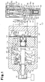
- Fig. 1 is a longitudinal cross-sectional view showing a variable displacement compressor and a displacement control valve in accordance with first and second embodiments;
- Fig. 2 is a longitudinal cross-sectional view showing the displacement control valve in accordance with the first and second embodiments;
- Fig. 3 is a partly enlarged cross-sectional view showing a valve portion and a valve seat in accordance with the first embodiment;
- Fig. 4 is a partly enlarged cross-sectional view showing the valve portion and the valve seat at a time when a valve body is tilted; and
- Fig. 5 is a partly enlarged cross-sectional view showing a valve portion and a valve seat in accordance with the second embodiment.
- A description will be given below of a first embodiment according to the present invention with reference to Figs. 1 to 4.
- As shown in Fig. 1, a
variable displacement compressor 10 is provided with acylinder block 11, and afront housing member 12 is attached to a front end of thecylinder block 11. Further, arear housing member 13 is attached to a rear end of thecylinder block 11 via a valve andport forming body 14. - A control pressure chamber C is defined between the
front housing member 12 and thecylinder block 11. In the control chamber C, a front end portion of ashaft body 18 is rotatably supported to thefront housing member 12 via a firstradial bearing 19, and a rear end portion of theshaft body 18 is rotatably supported to thecylinder block 11 via a secondradial bearing 20. Arotary support 21 is fixed to an approximately center of theshaft body 18, and aswash plate 22 is supported thereto in such a manner as to be slidable along an axis of theshaft body 18 and be tiltable with respect to the axis. Theswash plate 22 is coupled to therotary support 21 via ahinge mechanism 23. Thehinge mechanism 23 supports theswash plate 22 in such a manner as to be tiltable with respect to therotary support 21, and couples therotary support 21 and theswash plate 22 in such a manner that a torque is transmitted to theswash plate 22 from theshaft body 18. - If a center portion of the
swash plate 22 moves close to therotary support 21, inclination of theswash plate 22 with respect to the axis of theshaft body 18 becomes large. The inclination of theswash plate 22 is regulated on the basis of a contact between therotary support 21 and theswash plate 22. A solid line in Fig. 1 shows a state in which the inclination angle of theswash plate 22 is maximum, and a two-dot chain line shows a state in which the inclination angle of theswash plate 22 is minimum. - A plurality of cylinder bores 11a are formed in the
cylinder block 11. Apiston 24 is accommodated within each of the cylinder bores 11a (only one cylinder bore 11a is illustrated in Fig. 1). If theshaft body 18 is rotated and theswash plate 22 is rotated, a rotating motion is converted into a reciprocating motion of thepistons 24 within the cylinder bores 11a via shoes 25. Asuction chamber 13a and adischarge chamber 13b are defined within therear housing member 13. In this case, a suction pressure of the refrigerant gas in thesuction chamber 13a is referred to as Ps, and a discharge pressure of the refrigerant gas in thedischarge chamber 13b is referred to as Pd.Suction ports 14a and suction valve flaps 15a are formed in the valve andport forming body 14 in correspondence to thesuction chamber 13a, and dischargeports 14b and discharge valve flaps 15b are formed therein in correspondence to thedischarge chamber 13b. Further, a pressure of the refrigerant gas in the control pressure chamber C is referred to as a control pressure Pc. In the present embodiment, thesuction chamber 13a corresponds to the suction pressure zone, thedischarge chamber 13b corresponds to the discharge pressure zone, and the control pressure chamber C corresponds to the control pressure zone. - If each
piston 24 is moved to a front side (in a direction F shown in Fig. 1), the refrigerant gas within thesuction chamber 13a opens thesuction valve flap 15a and flows into the cylinder bore 11a from thesuction port 14a. If thepiston 24 is moved to a rear side (in a direction R shown in Fig. 1), the refrigerant gas flowing into the cylinder bore 11a opens thedischarge valve flap 15b and is discharged to thedischarge chamber 13b from thedischarge port 14b. On the basis of the reciprocating motion of thepistons 24 mentioned above, the refrigerant gas is discharged to thedischarge chamber 13b from the cylinder bores 11a, is thereafter supplied to an evaporation chamber G via a condensation chamber P and an expansion valve T, and is again returned to thesuction chamber 13a. In the present embodiment, the refrigerant circulation path is constituted by thevariable displacement compressor 10, the condensation chamber P, the expansion valve T and the evaporation chamber G. - An electromagnetic type
displacement control valve 32 is disposed in therear housing member 13 of thevariable displacement compressor 10. As shown in Fig. 2, adisplacement chamber 34 is defined within avalve housing 33 constituting a lower portion of adisplacement control valve 32. Further, avalve hole 35 communicating with thedisplacement chamber 34 is formed within thevalve housing 33. A diameter of thevalve hole 35 is smaller than a diameter of thedisplacement chamber 34. Further, avalve chamber 36 communicating with thevalve hole 35 is defined within thevalve housing 33. A diameter of thevalve chamber 36 is larger than the diameter of thevalve hole 35. A step is formed in a boundary portion between thevalve chamber 36 and thevalve hole 35, and the step is served as avalve seat 36a. - Further, an
actuation chamber 37 communicating with thevalve chamber 36 is defined within thevalve housing 33. Arod 31 is arranged within thevalve housing 33 so as to be movable along an axis L2 thereof. Therod 31 reciprocates within thevalve housing 33 while approximately bringing the axis L2 into line with an axis L1 of thevalve chamber 36. Avalve body 30 is fixed to a lower end portion of therod 31, and thevalve body 30 is arranged within thevalve chamber 36. Thevalve body 30 reciprocates within thevalve chamber 36 in accordance with the reciprocation of therod 31. - A
valve portion 30a of thevalve body 30 selectively contacts and separates from thevalve seat 36a in accordance with the reciprocation of therod 31. That is, if thevalve portion 30a contacts thevalve seat 36a, thevalve hole 35 is closed, and a seal structure is formed between thevalve portion 30a and thevalve seat 36a. On the basis of this seal structure, the leakage of the refrigerant gas is prevented. On the other hand, if thevalve portion 30a separates from thevalve seat 36a, thevalve hole 35 is opened, and the seal structure mentioned above is cancelled. - A
first communication path 38 communicating with thevalve chamber 36 is formed within the valve housing' 33. Thefirst communication path 38 communicates with adischarge chamber 13b of thevariable displacement compressor 10. The refrigerant gas having the discharge pressure Pd is introduced to thevalve chamber 36 from thedischarge chamber 13b via thefirst communication path 38. Further, adetection communication path 43 communicating with theactuation chamber 37 is formed withinthe'valve housing 33. Thedetection communication path 43 communicates with thesuction chamber 13a of thevariable displacement compressor 10. The refrigerant gas having the suction pressure Ps is introduced to theactuation chamber 37 from thesuction chamber 13a via thedetection communication path 43. In the present embodiment, thevalve chamber 36 corresponds to the discharge pressure zone, and theactuation chamber 37 corresponds to the suction pressure zone. - Further, a
second communication path 39 communicating with thedisplacement chamber 34 is formed within thevalve housing 33. A communication path 29 (refer to Fig. 1) communicating with the control pressure chamber C is formed in thevariable displacement compressor 10, and asecond communication path 39 of thedisplacement control valve 32 communicates with thecommunication path 29. The refrigerant gas having the discharge pressure Pd is supplied to the control pressure chamber C within thevariable displacement compressor 10 from thedisplacement control valve 32 via thecommunication path 29. In the present embodiment, the gas passage (the flow path) is constituted by thefirst communication path 38, thevalve chamber 36, thevalve hole 35 and thedisplacement chamber 34. - As shown in Fig. 3, an inner circumferential surface of the
valve chamber 36 is formed as aguide portion 40 for guiding the movement of thevalve body 30. Thevalve body 30 is reciprocated within thevalve chamber 36 along theguide portion 40 while approximately bringing an axis L3 thereof into line with the axis L1 of thevalve chamber 36. Further, theguide portion 40 sections thevalve chamber 36 and the actuation chamber 37 (refer to Fig. 2). In order to smoothly reciprocate thevalve body 30 within thevalve chamber 36, a predetermined clearance CL is formed between the inner circumferential surface of theguide portion 40 and an outer circumferential surface of thevalve body 30. In this case, a dimension of the clearance CL is set so as to prevent the refrigerant gas within thevalve chamber 36 from leaking to theactuation chamber 37. - As shown in Fig. 2, a
coupling portion 46 is installed to the lower end of therod 31, and anengagement portion 42 is detachably installed to thecoupling portion 46. Apressure sensing member 41 constituted by a bellows is arranged within thedisplacement chamber 34. An upper end of thepressure sensing member 41 is fixed to theengagement portion 42, and a lower end of thepressure sensing member 41 is fixed to thevalve housing 33. Aspring 50 is arranged within thepressure sensing member 41. An expansion and contraction amount of thepressure sensing member 41 is determined on the basis of a correlation between an urging force of the bellows and thespring 50, and the discharge pressure Pd and the control pressure Pc. When a moving speed of therod 31 is high, and thevalve body 30 is disconnected rapidly from thevalve seat 36a, thecoupling portion 46 is disconnected from theengagement portion 42. - An
open chamber 52 is formed between theengagement portion 42 and thecoupling portion 46, and anopen passage 53 corresponding to the flow path is formed within thevalve body 30 and therod 31. Theopen passage 53 extends along the axes L3 and L2 of thevalve body 30 and therod 31. Theopen passage 53 connects theopen chamber 52 with theactuation chamber 37, and allows the refrigerant gas to flow from theactuation chamber 37 to theopen chamber 52. Accordingly, theopen chamber 52 forms the suction pressure zone (the suction pressure Ps). - An
accommodation tube 61 is fixed within asolenoid housing 60 structuring the upper portion of thedisplacement control valve 32, and a fixediron core 62 is fixed within theaccommodation tube 61. Amovable iron core 63 is arranged between an upper wall of theaccommodation tube 61 and the fixediron core 62. Aspring 66 is arranged between the fixediron core 62 and themovable iron core 63. Themovable iron core 63 is urged in a direction moving away from the fixediron core 62 on the basis of the urging.force of thespring 66. Aninsertion hole 64 is formed in the center of the fixediron core 62, and therod 31 is movably arranged in theinsertion hole 64. Themovable iron core 63 is fixed to an upper end portion of therod 31. In order to make therod 31 movable, a predetermined clearance is formed between an outer circumferential surface of therod 31 and an inner circumferential surface of the fixediron core 62. - A
coil 67 is arranged within thesolenoid housing 60 so as to be along an outer periphery of theaccommodation tube 61. If an electric power is supplied to thecoil 67, an electromagnetic force is generated in correspondence to a magnitude of the electric power. Further, since thevalve body 30 moves downward together with therod 31 on the basis of the electromagnetic force, thevalve hole 35 is closed. In the present embodiment, asolenoid portion 59 corresponding to the actuation means is constituted by the fixediron core 62, themovable iron core 63, thespring 66 and thecoil 67. - On the other hand, in the case that the electric power is not supplied to the
coil 67, a position of thevalve body 30 in a height direction is determined on the basis of the suction pressure Ps of the refrigerant gas and the urging force of the pressure sensing member 41 (the spring 50), and an opened and closed state of thevalve hole 35 is determined. On the other hand, in the case that thecoil 67 is excited, the position of thevalve body 30 in the height direction is determined on the basis of the electromagnetic force from thecoil 67 in addition to the suction pressure Ps and the urging force of thepressure sensing member 41, and the opened and closed state of thevalve hole 35 is determined. An amount of the refrigerant gas having the discharge pressure Pd flowed into thedisplacement chamber 34 from thefirst communication path 38 is regulated by opening and closing thevalve hole 35. Further, it is possible to regulate an amount of the refrigerant gas having the discharge pressure Pd flowed into the control pressure chamber C within thevariable displacement compressor 10 via thesecond communication path 39 and thecommunication path 29. Accordingly, a differential pressure between the control pressure Pc of the control pressure chamber C and the suction pressure Ps of thesuction chamber 13a is changed, and an angle of inclination of theswash plate 22 of thevariable displacement compressor 10 is changed in correspondence to the differential pressure. As a result, a stroke amount of thepistons 24 is changed, and the displacement of thevariable displacement compressor 10 is regulated. - As shown in Fig. 3, the
valve seat 36a is tapered and is expanded toward the valve chamber 36' from thevalve hole 35. On the other hand, thevalve portion 30a of thevalve body 30 is formed in a circular arc cross sectional shape along a surface of an imaginary sphere K in which an intermediate point N of a length of theguide portion 40 along the axis L1 of thevalve chamber 36 is set to a center on the axis L1, and a distance from the intermediate point N to a contact point between avalve seat 36a and thevalve portion 30a is set to a radius r.. That is, when thevalve body 30 is brought into contact with thevalve seat 36a while bringing the axis L3 thereof into line with the axis L1 of thevalve chamber 36, thevalve portion 30a of thevalve body 30 and the surface (a circular arc of a virtual circle in Fig. 3) of the sphere K are partly in line. - In a state in which the
valve hole 35 is closed as mentioned above, thevalve portion 30a of thevalve body 30 is in line contact with the taperedvalve seat 36a. A seal structure is formed between thevalve portion 30a and thevalve seat 36a on the basis of the line contact between thevalve portion 30a and thevalve seat 36a. In thevalve portion 30a, a range forming the circular arc cross sectional shape is set while taking into consideration the clearance CL between thevalve body 30 and theguide portion 40. There is a case that the clearance CL that is formed along the outer circumferential surface of thevalve body 30 allows thevalve body 30 to tilt. As long as the range forming the circular arc cross sectional shape is properly set in thevalve portion 30a, the line contact between thevalve portion 30a and thevalve seat 36a is securely maintained even if thevalve body 30 is tilted. - Next, a description will be an operation in the case that the
rod 31 is tilted, with reference to Figs. 1 and 4. - As shown in Fig. 1, in the
displacement control valve 32 mentioned above, the clearance is formed between the outer circumferential surface of therod 31 and the inner circumferential surface of the fixediron core 62. As shown in Fig. 4, there is a possibility that thevalve body 30 is tilted together with therod 31 due to the clearance. At that time, in a state in which thevalve hole 35 is closed, there is a case that thevalve body 30 is tilted around the intermediate point N (the center of the sphere K) shown in Fig. 3. - In the present embodiment, the
valve portion 30a of thevalve body 30 is formed in the circular arc cross sectional shape along the surface (the circular arc of the virtual circle shown in Fig. 3) of the sphere K. Accordingly, even if thevalve body 30 is tilted,the'valve portion 30a is not disconnected from thevalve seat 36a, and the line contact between thevalve portion 30a and thevalve seat 36a is maintained. As a result, the gap is not formed between thevalve body 30 and thevalve seat 36a. - Further, the clearance CL exists along the outer circumferential surface of the
valve body 30, within theguide portion 40. Further, there is a case that thevalve body 30 is tilted around the intermediate point N (the center of the sphere K) shown in Fig. 3 due to the clearance CL. In the present embodiment, since thevalve portion 30a of thevalve body 30 is formed in the circular arc cross sectional shape along the surface of the sphere K.shown in Fig. 3, it is possible to securely maintain the line contact between thevalve portion 30a and thevalve seat 36a even if thevalve body 30 is tilted, and it is possible to maintain the seal structure formed between thevalve portion 30a and thevalve seat 36a. - In accordance with the first embodiment, the following advantages are obtained.
- (1) The
valve portion 30a of thevalve body 30 is formed in the circular arc cross sectional shape along the surface of the sphere K. Accordingly, since thevalve portion 30a is moved along the surface of the sphere K even if thevalve body 30 is tilted, it is possible to maintain the line contact between thevalve portion 30a and thevalve seat 36a. Therefore, it is possible to maintain the seal structure between thevalve portion 30a and thevalve seat 36a, and it is possible to prevent the refrigerant gas from leaking from the portion between thevalve portion 30a and thevalve seat 36a.
Particularly, in the case that theopen passage 53 is formed within therod 31 and thevalve body 30, the gap between thevalve portion 30a and thevalve seat 36a is prone to become large at a time when thevalve body 30 is tilted. On that point, in the present embodiment, since thevalve portion 30a is formed in the circular arc cross sectional shape along the surface of the sphere K, the line contact between thevalve portion 30a and thevalve seat 36a is maintained even if thevalve body 30 is tilted. Accordingly, since it is possible to maintain the seal structure between thevalve portion 30a and thevalve seat 36a, it is possible to prevent the refrigerant gas from leaking through the space between thevalve portion 30a and thevalve seat 36a. Accordingly, it is possible to close thevalve hole 35 while preventing the refrigerant gas from leaking, whereby it is possible to accurately control thedisplacement control valve 32. - (2) The
valve portion 30a is formed in the circular arc cross sectional shape along the surface of the sphere K. Accordingly, even if thevalve body 30 is tilted due to the clearance CL existing along the outer circumferential surface of thevalve body 30, it is possible to maintain the line contact between thevalve portion 30a and thevalve seat 36a. - (3) The range forming the circular arc cross sectional shape of the valve portion 3Oa is set by taking into consideration the clearance CL between the
valve body 30 and theguide portion 40. Accordingly, even if thevalve body 30 is tilted, it is possible to further prevent the gap from being formed between thevalve portion 30a and thevalve seat 36a. - (4) While the
valve portion 30a is formed in the circular arc cross sectional shape, thevalve seat 36a is formed in the taper shape. It is possible to bring thevalve portion 30a into line contact with the valve seat 3-6a on the basis of these shapes. In this case, it is possible to reduce a friction surface generated between thevalve portion 30a and thevalve seat 36a, in comparison with the case that thevalve portion 30a and thevalve seat 36a are brought into surface contact with each other. Accordingly, since the deformation of thevalve seat 36a due to the abrasion is suppressed, it is possible to contribute to the prevention of the leakage of the refrigerant gas. - Next, a description will be given of a second embodiment according to the present invention with reference to Fig. 5. Since the second embodiment is structured only by changing the shapes of the
valve portion 30a and thevalve seat 36a in the first embodiment, a detailed description of the same portions of those of the first embodiment will be omitted. - As shown in Fig. 5, the
valve portion 30a of thevalve body 30 is different from the first embodiment and is constituted by an end edge of thecolumnar valve body 30. In other words, thevalve portion 30a is constituted by a corner portion of thevalve body 30, and is formed in a right angle cross sectional shape. On the other hand, thevalve seat 36a of thevalve chamber 36 is formed in the circular arc cross sectional shape along the surface (the circular arc of the imaginary circle) of the imaginary sphere K in which the intermediate point N of the length of theguide portion 40 along the axis L1 of thevalve chamber 36 is set to the center on the axis L1, and the distance from the intermediate point N to the contact point between thevalve seat 36a and thevalve portion 30a is set to the radius r. Accordingly, since thevalve portion 30a is moved along the surface of the sphere K even if thevalve body 30 is tilted, it is possible to maintain the line contact between thevalve portion 30a and thevalve seat 36a. - Further, in this embodiment, since the
valve portion 30a is constituted by the corner portion of thevalve body 30, the pressure receiving surface receiving the pressure of the refrigerant gas does not exist in the lower surface of thevalve body 30 in a state in which thevalve hole 35 is closed. In other words, in the state in which thevalve hole 35 is closed, only the outer circumferential surface of thevalve body 30 forms the pressure receiving surface receiving the pressure of the refrigerant gas. - Therefore, in accordance with the second embodiment, the following advantage is achieved.
- (5) In the
displacement control valve 32 in accordance with the second embodiment, the pressure receiving surface receiving the pressure of the refrigerant gas does not exist in the lower surface of thevalve body 30, unlike the first embodiment. Accordingly, it is possible to minimize an influence to thevalve body 30 by the refrigerant gas from thefirst communication path 38. Therefore, even if the refrigerant gas is introduced to thevalve chamber 36, it is possible to prevent thevalve body 30 from moving to the upper side by the refrigerant gas so as to open thevalve hole 35. Accordingly, it is possible to more precisely execute the displacement control of thedisplacement control valve 32. - The embodiments mentioned above may be modified as follows.
- In each of the embodiments, the structure may be made such that the
valve portion 30a is formed in the circular arc cross sectional shape along the surface of the sphere K, and thevalve seat 36a is formed as the end edge of thevalve hole 35. In this case, in a state in which thevalve hole 35 is closed, a part of thevalve portion 30a of thevalve body 30 enters thevalve hole 35. - In each of the embodiments mentioned above, the structure may be made such that both of the
valve portion 30a and thevalve seat 36a are formed in the circular arc cross sectional shape along the surface of the sphere K, and thevalve portion 30a and thevalve seat 36a are brought into surface contact with each other. - In each of the embodiments mentioned above, the
displacement control valve 32 may be changed to other structures instead of the structure in each of the embodiments. For example, thedisplacement control valve 32 may be formed as a control valve executing the displacement control of thedisplacement control valve 32 in correspondence to the differential pressure of the discharge pressure. - In each of the embodiments mentioned above, the seal structure formed between the
valve portion 30a and thevalve seat 36a may be applied to other seal structures than thedisplacement control valve 32. For example, the seal structure may be applied to a seal structure of a refrigerant flow path of a refrigerant circulation path, a valve apparatus of a hydraulic circuit and the like. - In each of the embodiments mentioned above, a spring may be employed as the actuation means of the
displacement control valve 32, in place of thesolenoid portion 59. - A displacement control valve (32) is connected to a variable displacement compressor. An open passage (53) in which a refrigerant gas flows is formed within a rod (31) and a valve body (30) of the displacement control valve (32). Further, an inner circumferential surface of a valve chamber (36) is formed as a guide portion (40) for moving the valve body (30) along an axis (L1) of the valve chamber (36) A valve portion (30a) of the valve body (30) is formed in a circular arc cross sectional shape along a surface of a sphere (K) in which an intermediate point (N) of a length of the guide portion (40) along the axis (L1) of the valve chamber (36) is set to a center on the axis (L1), and a distance from the intermediate point (N) to a contact point between a valve seat (36a) and the valve portion (30a) is set to a radius (r).
Claims (8)
- A displacement control valve that forms a part of a circulation path of a refrigerant gas, used in a variable displacement compressor capable of changing a displacement of the refrigerant gas, and provided with a valve chamber forming a part of a gas passage in which the refrigerant gas flows, a valve body movably arranged within the valve chamber and selectively contacting and separating from a valve seat of the valve chamber, thereby selectively opening and closing the gas passage, a rod integrally moving with the valve body, actuation means for actuating the rod for positioning the valve body, a flow passage provided within the rod and the valve body, and causing the refrigerant gas to flow, and a guide portion for moving the valve body along an axis of the valve chamber,
the displacement control valve being characterized in that at least one of the valve portion and the valve seat is formed along a surface of an imaginary sphere in which an intermediate point of a length of the guide portion along the axis of the valve chamber is set to a center on the axis, and a distance from the intermediate point to the contact point between the valve seat and the valve portion is set to a radius. - The displacement control valve according to claim 1, characterized in that only the valve portion is formed in a circular arc cross sectional shape.
- The displacement control valve according to claim 1, characterized in that the valve seat is formed in a circular arc cross sectional shape, and the valve portion is formed by an end edge of the valve body.
- The displacement control valve according to any one of claims 1 to 3, characterized in that the valve seat and the valve portion are in line contact.
- A seal structure of a valve apparatus, the seal structure comprising: a valve chamber provided within the valve apparatus and forming a flow path in which a fluid flows; a valve body movably arranged within the valve chamber, and contacting and separating from a valve seat of the valve chamber, thereby opening and closing the flow path; a rod integrally moving with the valve body; actuation means for actuating the rod for positioning the valve body; a flow passage provided within the rod and'the valve body, and causing the fluid to flow therethrough; and a guide portion for moving the valve body along an axis of the valve chamber,
the seal structure being characterized in that at least one of the valve portion and the valve seat is formed along a surface of an imaginary sphere in which an intermediate point of a length of the guide portion along the axis of the valve chamber is set to a center on the axis, and a distance from the intermediate point to the contact point between the valve seat and the valve portion is set to a radius. - The seal structure of a valve apparatus according to claim 5, characterized in that the flow path is formed by a gas passage connecting a control pressure zone and a discharge pressure zone in a variable displacement compressor forming a part of the refrigerant circulation path, and the fluid is a refrigerant gas compressed by the variable displacement compressor.
- The seal structure of a valve apparatus according to claim 5 or 6, characterized in that the valve portion is formed in a circular arc cross sectional shape.
- The seal structure of a valve apparatus according to claims 5 to 7, characterized in that the valve seat is formed in a circular arc cross sectional shape, and the valve portion is formed by an end edge of the valve body.
Applications Claiming Priority (1)
| Application Number | Priority Date | Filing Date | Title |
|---|---|---|---|
| JP2005168707A JP4516892B2 (en) | 2005-06-08 | 2005-06-08 | Capacity control valve of variable capacity compressor |
Publications (3)
| Publication Number | Publication Date |
|---|---|
| EP1731763A2 true EP1731763A2 (en) | 2006-12-13 |
| EP1731763A3 EP1731763A3 (en) | 2010-11-24 |
| EP1731763B1 EP1731763B1 (en) | 2012-07-18 |
Family
ID=36685936
Family Applications (1)
| Application Number | Title | Priority Date | Filing Date |
|---|---|---|---|
| EP06115175A Active EP1731763B1 (en) | 2005-06-08 | 2006-06-08 | Displacement control valve of variable displacement compressor |
Country Status (5)
| Country | Link |
|---|---|
| US (1) | US7806666B2 (en) |
| EP (1) | EP1731763B1 (en) |
| JP (1) | JP4516892B2 (en) |
| KR (1) | KR100793124B1 (en) |
| CN (1) | CN100513784C (en) |
Families Citing this family (21)
| Publication number | Priority date | Publication date | Assignee | Title |
|---|---|---|---|---|
| CN101410620B (en) * | 2006-03-15 | 2011-03-23 | 伊格尔工业股份有限公司 | Capacity control valve |
| JP4695032B2 (en) * | 2006-07-19 | 2011-06-08 | サンデン株式会社 | Volume control valve for variable capacity compressor |
| JP2008038856A (en) * | 2006-08-10 | 2008-02-21 | Toyota Industries Corp | Control valve for variable displacement compressor |
| JP4861956B2 (en) * | 2007-10-24 | 2012-01-25 | 株式会社豊田自動織機 | Capacity control valve in variable capacity compressor |
| JP4959525B2 (en) * | 2007-11-29 | 2012-06-27 | 株式会社不二工機 | Control valve for variable displacement compressor |
| JP2009221965A (en) * | 2008-03-17 | 2009-10-01 | Sanden Corp | Capacity control valve of variable displacement compressor, and reciprocating type variable displacement compressor |
| JP5281320B2 (en) * | 2008-05-28 | 2013-09-04 | サンデン株式会社 | Capacity control system for variable capacity compressor |
| JP2011163313A (en) * | 2010-02-15 | 2011-08-25 | Shinhan Electro-Mechanics Co Ltd | Capacity control valve for variable displacement compressor, and assembling method of the same |
| JP5907432B2 (en) * | 2011-06-15 | 2016-04-26 | イーグル工業株式会社 | Capacity control valve |
| CN103452813B (en) * | 2012-05-31 | 2017-07-04 | 华域三电汽车空调有限公司 | The control valve of variable compressor |
| JP6136461B2 (en) | 2013-03-29 | 2017-05-31 | 株式会社豊田自動織機 | Variable capacity compressor |
| EP3564528B1 (en) * | 2016-12-28 | 2022-08-03 | Eagle Industry Co., Ltd. | Capacity control valve |
| JP7051238B2 (en) * | 2017-02-18 | 2022-04-11 | イーグル工業株式会社 | Capacity control valve |
| CN110770441B (en) | 2017-07-05 | 2021-12-14 | 伊格尔工业股份有限公司 | volume control valve |
| WO2019009266A1 (en) * | 2017-07-06 | 2019-01-10 | イーグル工業株式会社 | Capacity control valve |
| CN107975470A (en) * | 2017-11-27 | 2018-05-01 | 山西中航锦恒科技有限公司 | A kind of motor-operated control valve of inside with throttling arrangement |
| US11994120B2 (en) | 2018-07-12 | 2024-05-28 | Eagle Industry Co., Ltd. | Capacity control valve |
| CN112513460B (en) | 2018-08-08 | 2023-04-28 | 伊格尔工业股份有限公司 | Capacity control valve |
| CN109442068B (en) * | 2018-12-29 | 2024-04-26 | 绵阳富临精工机械股份有限公司 | An electric control valve structure with exhaust channel |
| US12292130B2 (en) * | 2019-01-21 | 2025-05-06 | Eagle Industry Co., Ltd. | Capacity control valve |
| CN115427684B (en) | 2020-04-23 | 2025-08-05 | 伊格尔工业股份有限公司 | Capacity control valve |
Family Cites Families (12)
| Publication number | Priority date | Publication date | Assignee | Title |
|---|---|---|---|---|
| JPS53166125U (en) | 1977-06-03 | 1978-12-26 | ||
| JPS6427487U (en) | 1987-08-10 | 1989-02-16 | ||
| JPH066855U (en) * | 1992-06-26 | 1994-01-28 | エヌオーケー株式会社 | Control valve |
| US5702235A (en) * | 1995-10-31 | 1997-12-30 | Tgk Company, Ltd. | Capacity control device for valiable-capacity compressor |
| JP3432995B2 (en) * | 1996-04-01 | 2003-08-04 | 株式会社豊田自動織機 | Control valve for variable displacement compressor |
| JPH10332016A (en) * | 1997-05-28 | 1998-12-15 | Kubota Corp | Air valve |
| JP2000249051A (en) | 1999-03-01 | 2000-09-12 | Toyota Autom Loom Works Ltd | Control valve for variable displacement swash plate type compressor |
| JP2001132632A (en) * | 1999-11-10 | 2001-05-18 | Toyota Autom Loom Works Ltd | Control valve of variable displacement compressor |
| JP2002364533A (en) * | 2001-06-07 | 2002-12-18 | Saginomiya Seisakusho Inc | Solenoid control valve |
| JP4246975B2 (en) * | 2002-02-04 | 2009-04-02 | イーグル工業株式会社 | Capacity control valve |
| JP4242624B2 (en) * | 2002-09-26 | 2009-03-25 | イーグル工業株式会社 | Capacity control valve and control method thereof |
| JP4331653B2 (en) * | 2004-05-31 | 2009-09-16 | 株式会社テージーケー | Control valve for variable capacity compressor |
-
2005
- 2005-06-08 JP JP2005168707A patent/JP4516892B2/en not_active Expired - Lifetime
-
2006
- 2006-06-07 US US11/449,419 patent/US7806666B2/en active Active
- 2006-06-08 EP EP06115175A patent/EP1731763B1/en active Active
- 2006-06-08 CN CNB2006100945105A patent/CN100513784C/en active Active
- 2006-06-08 KR KR1020060051650A patent/KR100793124B1/en active Active
Non-Patent Citations (1)
| Title |
|---|
| None |
Also Published As
| Publication number | Publication date |
|---|---|
| EP1731763A3 (en) | 2010-11-24 |
| EP1731763B1 (en) | 2012-07-18 |
| JP2006342718A (en) | 2006-12-21 |
| US20060280616A1 (en) | 2006-12-14 |
| US7806666B2 (en) | 2010-10-05 |
| CN1877123A (en) | 2006-12-13 |
| CN100513784C (en) | 2009-07-15 |
| KR100793124B1 (en) | 2008-01-10 |
| JP4516892B2 (en) | 2010-08-04 |
| KR20060128713A (en) | 2006-12-14 |
Similar Documents
| Publication | Publication Date | Title |
|---|---|---|
| EP1731763B1 (en) | Displacement control valve of variable displacement compressor | |
| US6010312A (en) | Control valve unit with independently operable valve mechanisms for variable displacement compressor | |
| EP2366901B1 (en) | Variable displacement compressor | |
| EP2113662B1 (en) | Variable displacement type compressor with displacement control mechanism | |
| EP1936192A2 (en) | Electromagnetic displacement control valve in clutchless type variable displacement compressor | |
| US20050287014A1 (en) | Displacement control valve for variable displacement compressor | |
| KR20090042171A (en) | Capacity control valve in variable displacement compressor | |
| EP1918583A2 (en) | Suction throttle valve of a compressor | |
| EP2784319B1 (en) | Double-headed piston swash plate type compressor | |
| KR100462032B1 (en) | Control valve of variable displacement compressor | |
| KR19980064124A (en) | Control Valves for Variable Capacity Compressors | |
| EP1890036A2 (en) | Displacement control valve for variable displacement compressor | |
| US8439652B2 (en) | Suction throttle valve for variable displacement type compressor | |
| EP1236899B1 (en) | Control valve for variable displacement compressor using electromagnetic actuator | |
| US6443707B1 (en) | Control valve for variable displacement compressor | |
| KR20030069040A (en) | Control device for variable displacement compressor | |
| KR100726752B1 (en) | Capacity control valves for clutchless variable displacement compressors | |
| EP1033489A2 (en) | Displacement control valve for variable displacement type compressors | |
| EP2784318B1 (en) | Variable displacement swash plate compressor | |
| EP1936191A2 (en) | Variable displacement compressor | |
| US20160047366A1 (en) | Variable displacement swash plate type compressor | |
| KR100455239B1 (en) | Control valve for a variable capacity compressor | |
| EP1081379A1 (en) | Control valve for variable displacement compressor | |
| JP2019002383A (en) | Control valve of variable displacement compressor | |
| JP2016169697A (en) | Variable capacity type swash plate compressor |
Legal Events
| Date | Code | Title | Description |
|---|---|---|---|
| PUAI | Public reference made under article 153(3) epc to a published international application that has entered the european phase |
Free format text: ORIGINAL CODE: 0009012 |
|
| 17P | Request for examination filed |
Effective date: 20060608 |
|
| AK | Designated contracting states |
Kind code of ref document: A2 Designated state(s): AT BE BG CH CY CZ DE DK EE ES FI FR GB GR HU IE IS IT LI LT LU LV MC NL PL PT RO SE SI SK TR |
|
| AX | Request for extension of the european patent |
Extension state: AL BA HR MK YU |
|
| RAP1 | Party data changed (applicant data changed or rights of an application transferred) |
Owner name: EAGLE INDUSTRY CO., LTD. |
|
| PUAL | Search report despatched |
Free format text: ORIGINAL CODE: 0009013 |
|
| AK | Designated contracting states |
Kind code of ref document: A3 Designated state(s): AT BE BG CH CY CZ DE DK EE ES FI FR GB GR HU IE IS IT LI LT LU LV MC NL PL PT RO SE SI SK TR |
|
| AX | Request for extension of the european patent |
Extension state: AL BA HR MK RS |
|
| 17Q | First examination report despatched |
Effective date: 20110318 |
|
| AKX | Designation fees paid |
Designated state(s): DE FR IT |
|
| GRAP | Despatch of communication of intention to grant a patent |
Free format text: ORIGINAL CODE: EPIDOSNIGR1 |
|
| RTI1 | Title (correction) |
Free format text: DISPLACEMENT CONTROL VALVE OF VARIABLE DISPLACEMENT COMPRESSOR |
|
| GRAS | Grant fee paid |
Free format text: ORIGINAL CODE: EPIDOSNIGR3 |
|
| GRAA | (expected) grant |
Free format text: ORIGINAL CODE: 0009210 |
|
| AK | Designated contracting states |
Kind code of ref document: B1 Designated state(s): DE FR IT |
|
| REG | Reference to a national code |
Ref country code: DE Ref legal event code: R096 Ref document number: 602006030811 Country of ref document: DE Effective date: 20120913 |
|
| PLBE | No opposition filed within time limit |
Free format text: ORIGINAL CODE: 0009261 |
|
| STAA | Information on the status of an ep patent application or granted ep patent |
Free format text: STATUS: NO OPPOSITION FILED WITHIN TIME LIMIT |
|
| 26N | No opposition filed |
Effective date: 20130419 |
|
| REG | Reference to a national code |
Ref country code: DE Ref legal event code: R097 Ref document number: 602006030811 Country of ref document: DE Effective date: 20130419 |
|
| REG | Reference to a national code |
Ref country code: FR Ref legal event code: PLFP Year of fee payment: 11 |
|
| REG | Reference to a national code |
Ref country code: FR Ref legal event code: PLFP Year of fee payment: 12 |
|
| REG | Reference to a national code |
Ref country code: FR Ref legal event code: PLFP Year of fee payment: 13 |
|
| PGFP | Annual fee paid to national office [announced via postgrant information from national office to epo] |
Ref country code: DE Payment date: 20250429 Year of fee payment: 20 |
|
| PGFP | Annual fee paid to national office [announced via postgrant information from national office to epo] |
Ref country code: IT Payment date: 20250522 Year of fee payment: 20 |
|
| PGFP | Annual fee paid to national office [announced via postgrant information from national office to epo] |
Ref country code: FR Payment date: 20250508 Year of fee payment: 20 |