EP1731740A1 - System and method for fuel injection control of a Diesel engine of an automotive vehicle - Google Patents
System and method for fuel injection control of a Diesel engine of an automotive vehicle Download PDFInfo
- Publication number
- EP1731740A1 EP1731740A1 EP06290905A EP06290905A EP1731740A1 EP 1731740 A1 EP1731740 A1 EP 1731740A1 EP 06290905 A EP06290905 A EP 06290905A EP 06290905 A EP06290905 A EP 06290905A EP 1731740 A1 EP1731740 A1 EP 1731740A1
- Authority
- EP
- European Patent Office
- Prior art keywords
- injection
- interval
- crankshaft angle
- late
- combustion
- Prior art date
- Legal status (The legal status is an assumption and is not a legal conclusion. Google has not performed a legal analysis and makes no representation as to the accuracy of the status listed.)
- Granted
Links
Images


Classifications
-
- F—MECHANICAL ENGINEERING; LIGHTING; HEATING; WEAPONS; BLASTING
- F02—COMBUSTION ENGINES; HOT-GAS OR COMBUSTION-PRODUCT ENGINE PLANTS
- F02D—CONTROLLING COMBUSTION ENGINES
- F02D41/00—Electrical control of supply of combustible mixture or its constituents
- F02D41/30—Controlling fuel injection
- F02D41/38—Controlling fuel injection of the high pressure type
- F02D41/40—Controlling fuel injection of the high pressure type with means for controlling injection timing or duration
- F02D41/402—Multiple injections
- F02D41/405—Multiple injections with post injections
-
- F—MECHANICAL ENGINEERING; LIGHTING; HEATING; WEAPONS; BLASTING
- F02—COMBUSTION ENGINES; HOT-GAS OR COMBUSTION-PRODUCT ENGINE PLANTS
- F02D—CONTROLLING COMBUSTION ENGINES
- F02D35/00—Controlling engines, dependent on conditions exterior or interior to engines, not otherwise provided for
- F02D35/02—Controlling engines, dependent on conditions exterior or interior to engines, not otherwise provided for on interior conditions
- F02D35/023—Controlling engines, dependent on conditions exterior or interior to engines, not otherwise provided for on interior conditions by determining the cylinder pressure
-
- F—MECHANICAL ENGINEERING; LIGHTING; HEATING; WEAPONS; BLASTING
- F02—COMBUSTION ENGINES; HOT-GAS OR COMBUSTION-PRODUCT ENGINE PLANTS
- F02D—CONTROLLING COMBUSTION ENGINES
- F02D35/00—Controlling engines, dependent on conditions exterior or interior to engines, not otherwise provided for
- F02D35/02—Controlling engines, dependent on conditions exterior or interior to engines, not otherwise provided for on interior conditions
- F02D35/028—Controlling engines, dependent on conditions exterior or interior to engines, not otherwise provided for on interior conditions by determining the combustion timing or phasing
-
- Y—GENERAL TAGGING OF NEW TECHNOLOGICAL DEVELOPMENTS; GENERAL TAGGING OF CROSS-SECTIONAL TECHNOLOGIES SPANNING OVER SEVERAL SECTIONS OF THE IPC; TECHNICAL SUBJECTS COVERED BY FORMER USPC CROSS-REFERENCE ART COLLECTIONS [XRACs] AND DIGESTS
- Y02—TECHNOLOGIES OR APPLICATIONS FOR MITIGATION OR ADAPTATION AGAINST CLIMATE CHANGE
- Y02T—CLIMATE CHANGE MITIGATION TECHNOLOGIES RELATED TO TRANSPORTATION
- Y02T10/00—Road transport of goods or passengers
- Y02T10/10—Internal combustion engine [ICE] based vehicles
- Y02T10/40—Engine management systems
Definitions
- the present invention relates to a system and a method for controlling the operation of a motor vehicle diesel engine.
- the present invention relates to such a method and such a system for an engine equipped with fuel supply means of the cylinders thereof according to at least one main injection and a late injection of fuel according to a predetermined setpoint. Crankshaft angle interval separation of the late injection of the main injection.
- the fuel supply of a cylinder of a diesel engine of a motor vehicle is divided into at least one injection main fuel located substantially at the top dead center of the cylinder cycle and one or more late fuel injections during the relaxation phase of the cycle.
- control systems of the fuel supply of the prior art cylinders open-loop late injection according to a predetermined set of crank angle angles.
- these systems do not guarantee that the real interval separating these two injections is equal to the interval setpoint and are generally very sensitive to any type of disturbance, such as the aging of the cylinder injector by example.
- the emission of pollutants can rapidly deteriorate and a registration of the injection of fuel into the cylinder, or even a replacement of worn parts, is then regularly necessary to ensure an optimum emission level of pollutants.
- the object of the present invention is to solve the aforementioned problems by proposing a system for controlling the operation of a motor vehicle diesel engine that is less sensitive to disturbances on the fuel injection characteristics in the cylinders thereof.
- the subject of the present invention is a system for controlling the operation of a motor vehicle diesel engine equipped with means for supplying the cylinders with fuel in at least one main injection and a late injection of fuel. according to a predetermined set of crankshaft separation interval separation of the late injection of the main injection, characterized in that it comprises means for estimating the crank angle interval separating the late injection of the main injection in at least one cylinder and control means of the supply means adapted to enslave this estimated interval on the interval setpoint.
- the present invention also relates to a method for controlling the operation of a motor vehicle diesel engine comprising means for supplying the cylinders with fuel in at least one main injection and a late injection of fuel as a function of the engine. a predetermined set of crank angle intervals separation of the late injection of the main injection, characterized in that it comprises a step of estimating the crank angle interval separating the late injection of the main injection into at least one cylinder and a piloting step of supply means for slaving this estimated interval to the interval setpoint.
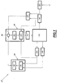
- FIG. 1 there is schematically illustrated a system 10 for controlling the operation of a diesel engine 12 of a motor vehicle.
- This engine 12 is equipped with means 14 common rail fuel supply cylinders thereof.
- the power supply means 14 are controlled by means 16 for controlling their operation and information processing.
- the means 16 are adapted to drive the means 14 so that the latter feed each cylinder of the engine 12 according to a pilot injection, a main injection and at least one late injection during the relaxation phase of the cylinder cycle.
- the motor 12 is associated with a chain 18 for acquiring its rotation speed and a chain 20 for acquiring the desired engine torque by the driver of the vehicle, these acquisition chains being known per se in the state of the art. .
- These chains 18, 20 are connected to means 22 forming a map comprising a predetermined map of fuel injection instructions in each cylinder as a function of torque values of rotation speed and engine torque.
- These mapping means 22 are able to evaluate, for the speed and the torque acquired by the chains 18 and 20, their mapping of instructions and to deliver to the means 16 piloting a corresponding fuel injection instruction in the cylinders, as is known per se in the state of the art.
- mapping means 22 are adapted to deliver, as a function of the speed and torque acquired, a crankshaft angle interval setpoint separating the late injection from the main injection.
- the engine 12 is also associated with chains 24, 26 for acquiring the crankshaft angle and the pressure in the combustion chamber, or cylinder pressure, of each cylinder of the engine.
- the system 10 comprises, connected to the chains 24, 26 for acquisition of the crankshaft angle and the cylinder cylinder pressure and to the control means 16, means 28 for estimating the range of angles. crankshaft separating the late injection from the main injection of fuel into the cylinder, as will be explained in more detail later.
- the control means 16 are adapted to implement a servocontrol of the range of angles estimated by the means 28 to the angle interval setpoint delivered by the means 22 forming a map.
- control means 16 are able to implement a regulation of the estimated interval on the interval setpoint so that the actual crank angle interval between the late injection on the main injection is substantially equal to the interval setpoint.
- the control means 32 comprise, for example, a self-adaptive mapping and / or a cycle-to-cycle regulator or a combination thereof.
- the slow loop may, for example, include a so-called "self-adaptive" mapping that makes it possible to store and update interval errors according to their location in the motor field defined for example by the engine torque and the speed.
- the means 28 for estimating the crankshaft angle interval separating the late injection and the main injection comprise means 36 for calculating the instantaneous release of heat caused by the combustion of the mixture of fuel and fresh gas, or mixture in the cylinder during the combustion phase of the cycle thereof.
- d Q d ⁇ 1 k - 1 ⁇ V ⁇ d P d ⁇ - k ⁇ P ⁇ d V d ⁇
- d ⁇ is a predetermined variation of the crankshaft angle ⁇ of the cylinder
- dQ is the amount of instantaneous heat released by the combustion of the mixture during the variation d ⁇ of the crankshaft angle
- V and P are the volume of the combustion chamber and the pressure therein at the moment of commencement of the variation d ⁇ of the crankshaft angle respectively, the volume V being for example tabulated in the means 36 as a function of the crankshaft angle
- dV and dP are the variations of the volume the combustion chamber and the pressure therein corresponding to the variation d ⁇ of the crankshaft angle respectively
- k a predetermined polytropic coefficient.
- the means 36 for calculating the heat evolution are connected to estimating means 38 adapted to estimate the crankshaft angle interval separating the late injection from the main injection as a function of the calculated heat release, in a manner which will be explained in more detail later.
- FIG. 2 is a graph of a heat release curve calculated by the calculation means 36 as a function of the crankshaft angle of the cylinder for a predetermined range of crankshaft angles [ ⁇ _min, ⁇ _max] of the cylinder in which the pilot and main injections as well as late injection.
- This range is for example equal to [-20, 90] degrees crankshaft, the zero corresponding to the top dead center of the cylinder cycle, and this range will be designated in the rest of the description by the terms "search" range.
- a step 50 the rotation speed of the motor 12 and the desired torque by the driver are acquired by the acquisition chains 18, 20 and an interval setpoint is determined. by the means 22 forming mapping according to them.
- a next step 52 the cylinder pressure and the crankshaft angle of the cylinder are acquired by the acquisition chains 24, 36 for the current engine cycle, then, at 54, the heat release for the search range is calculated by the calculation means 36 as a function of the pressure and the acquired crankshaft angle.
- a step 56 of estimating the interval of angles separating the late injection from the main injection is then triggered.
- This step 56 implemented by the estimating means 38, comprises a step 58 of determining the maximum h_max of the heat release on the search range [ ⁇ _min, ⁇ _max] and its corresponding crankshaft angle a_peak.
- This global maximum over the range [ ⁇ _min, ⁇ _max] corresponds to the maximum heat released during the combustion of the mixture resulting from the main injection.
- a step 60 the set of local minima, and their corresponding angular positions, are determined over the range of angles [ ⁇ _min, ⁇ _peak]. For example, these minima and their crank angles are calculated by determining the angular positions for which the derivative of the heat generation calculated by the means 36 is canceled and changes sign by passing from a negative value to a positive value.
- the minimum of the determined minima whose angular position ⁇ _1 is closest to the angular position ⁇ _peak of the maximum h_max is selected at 62 and the value h_1 of the heat release for the angle ⁇ _1 is stored.
- a crankshaft angle ⁇ _soc of the start of the combustion of the mixture resulting from the main injection is then determined at 64 by selecting the crankshaft angle of the range [ ⁇ _1, ⁇ _peak] for which the value of the release of heat is substantially equal to the sum h_1 + h_hreshold heat release value h_1 for angle ⁇ _1 and a predetermined threshold value h_seuil.
- the threshold value h_seuil is preferably between 0 and 5 J / deg.
- the operation of the system according to the invention is then continued by determining the combustion start angle of the late injection in a crankshaft angle range substantially comprising that it, for example the range [ ⁇ _peak, ⁇ _max] .
- a step 66 of step 56 of estimating the interval separating the late injection from the main injection consists in determining the set of maxima and minima of the release of heat in the range of angles. crankshaft [ ⁇ _peak, ⁇ _max].
- a difference ⁇ Q1, ⁇ Q2,..., ⁇ Qn between the release of heat for this minimum and the release of heat for the successive maximum and the closest thereto is calculated.
- the maximum of the deviations ⁇ Q1, ⁇ Q2,..., ⁇ Qn thus calculated is selected at 70.
- the angular position ⁇ _split of the minimum of the selected deviation corresponds to the crankshaft start angle of the combustion in the cylinder of the mixture coming from late injection.
- crank angle interval separating the late injection from the main injection is then calculated at 72.
- the interval separating these injections is defined as being the crankshaft angle interval ⁇ 1 separating the ⁇ _split angle from the start of combustion of the mixture resulting from the late injection of the ⁇ _soc angle of the beginning. combustion of the mixture from the main injection.
- the interval separating these injections is defined as being the crankshaft angle interval ⁇ 2 separating the angle ⁇ _split from the start of combustion of the mixture resulting from the late injection of the angle ⁇ _peak of the maximum combustion of the mixture from the main injection.
- a next step 74 of the operation of the system of FIG. 1 is a step of regulating the estimated interval on the interval setpoint and is implemented by the means 16 for controlling the supply means.
- This step 74 comprises a step 76 of formation by the subtractor 60 of the difference between the interval setpoint determined at 50 and the estimated interval at 56.
- a regulation signal is then calculated at 78 by the regulating means 32 as a function of this difference and then delivered to the means 34 for controlling the supply means 14.
- the means 34 then control at 80 the supply means 14 as a function of the calculated regulation signal and then step 80 loops on step 50 for a new calculation cycle.
- crankshaft angle interval separating the late injection from the main injection in the cylinder is regulated on the interval setpoint delivered by the means 22 forming injection instructions.
Abstract
Description
La présente invention concerne un système et un procédé de contrôle du fonctionnement d'un moteur Diesel de véhicule automobile.The present invention relates to a system and a method for controlling the operation of a motor vehicle diesel engine.
Plus particulièrement, la présente invention concerne un tel procédé et un tel système pour un moteur équipé de moyens d'alimentation en carburant des cylindres de celui-ci selon au moins une injection principale et une injection tardive de carburant en fonction d'une consigne prédéterminée d'intervalle d'angles vilebrequin de séparation de l'injection tardive de l'injection principale.More particularly, the present invention relates to such a method and such a system for an engine equipped with fuel supply means of the cylinders thereof according to at least one main injection and a late injection of fuel according to a predetermined setpoint. Crankshaft angle interval separation of the late injection of the main injection.
De manière typique, l'alimentation en carburant d'un cylindre d'un moteur Diesel de véhicule automobile, et plus particulièrement l'alimentation d'un moteur Diesel équipé d'une rampe commune d'alimentation, est fractionnée en au moins une injection principale de carburant située sensiblement au point mort haut du cycle du cylindre et une ou plusieurs injections tardives de carburant lors de la phase de détente du cycle.Typically, the fuel supply of a cylinder of a diesel engine of a motor vehicle, and more particularly the supply of a diesel engine equipped with a common supply rail, is divided into at least one injection main fuel located substantially at the top dead center of the cylinder cycle and one or more late fuel injections during the relaxation phase of the cycle.
L'utilisation d'une ou plusieurs de ces injections tardives a pour effet de minimiser la quantité de polluants émise par le moteur tout en conservant un niveau de bruit de combustion satisfaisant.The use of one or more of these late injections has the effect of minimizing the amount of pollutants emitted by the engine while maintaining a satisfactory level of combustion noise.
Or de manière typique, une variation dans les caractéristiques d'une post-injection, et tout particulièrement l'intervalle d'angles vilebrequin la séparant de l'injection principale, induit une variation importante de la quantité de polluants émise.Typically, a variation in the characteristics of a post-injection, and especially the crank angle interval separating it from the main injection, induces a significant variation in the amount of pollutants emitted.
Toutefois, les systèmes de contrôle de l'alimentation en carburant des cylindres de l'état de la technique commandent en boucle ouverte l'injection tardive en fonction d'une consigne prédéterminée d'intervalle d'angles vilebrequin. De fait, ces systèmes ne garantissent pas que l'intervalle réel séparant ces deux injections soit égal à la consigne d'intervalle et sont d'une manière générale très sensibles à tout type de perturbation, comme le vieillissement de l'injecteur du cylindre par exemple.However, the control systems of the fuel supply of the prior art cylinders open-loop late injection according to a predetermined set of crank angle angles. In fact, these systems do not guarantee that the real interval separating these two injections is equal to the interval setpoint and are generally very sensitive to any type of disturbance, such as the aging of the cylinder injector by example.
Ainsi, l'émission de polluants peut rapidement se dégrader et un recalage de l'injection de carburant dans le cylindre, voire un remplacement des pièces usées, est alors régulièrement nécessaire pour garantir un niveau d'émission de polluants optimum.Thus, the emission of pollutants can rapidly deteriorate and a registration of the injection of fuel into the cylinder, or even a replacement of worn parts, is then regularly necessary to ensure an optimum emission level of pollutants.
Le but de la présente invention est de résoudre les problèmes susmentionnés en proposant un système de contrôle du fonctionnement d'un moteur Diesel de véhicule automobile moins sensible aux perturbations sur les caractéristiques d'injection de carburant dans les cylindres de celui-ci.The object of the present invention is to solve the aforementioned problems by proposing a system for controlling the operation of a motor vehicle diesel engine that is less sensitive to disturbances on the fuel injection characteristics in the cylinders thereof.
A cet effet, la présente invention a pour objet un système de contrôle du fonctionnement d'un moteur Diesel de véhicule automobile équipé de moyens d'alimentation en carburant des cylindres de celui-ci selon au moins une injection principale et une injection tardive de carburant en fonction d'une consigne prédéterminée d'intervalle d'angles vilebrequin de séparation de l'injection tardive de l'injection principale, caractérisé en ce qu'il comprend des moyens d'estimation de l'intervalle d'angles vilebrequin séparant l'injection tardive de l'injection principale dans au moins un cylindre et des moyens de pilotage des moyens d'alimentation propres à asservir cet intervalle estimé sur la consigne d'intervalle.For this purpose, the subject of the present invention is a system for controlling the operation of a motor vehicle diesel engine equipped with means for supplying the cylinders with fuel in at least one main injection and a late injection of fuel. according to a predetermined set of crankshaft separation interval separation of the late injection of the main injection, characterized in that it comprises means for estimating the crank angle interval separating the late injection of the main injection in at least one cylinder and control means of the supply means adapted to enslave this estimated interval on the interval setpoint.
Suivant des modes particuliers de réalisation, le système comporte une ou plusieurs des caractéristiques suivantes :
- des moyens d'acquisition de la pression cylindre et de l'angle vilebrequin du au moins un cylindre, et les moyens d'estimation de l'intervalle d'angles vilebrequin séparant l'injection tardive de l'injection principale comprennent des moyens de détermination du dégagement de chaleur provoqué par la combustion du mélange dans le au moins un cylindre en fonction de la pression et de l'angle vilebrequin acquis et des moyens d'estimation de l'intervalle d'angles vilebrequin séparant l'injection tardive de l'injection principale en fonction du dégagement de chaleur déterminé ;
- les moyens d'estimation de l'intervalle d'angles vilebrequin en fonction du dégagement de chaleur sont propres à déterminer l'angle vilebrequin (α_peak) du maximum (h_max) du dégagement de chaleur déterminée et un angle vilebrequin (α_split) de début de combustion d'un mélange issu de l'injection tardive et à calculer l'intervalle d'angles vilebrequin séparant l'injection tardive de l'injection principale en fonction de la différence entre l'angle vilebrequin (α_split) de début de combustion du mélange issu de l'injection tardive et l'angle (α_peak) du maximum (h_max) de dégagement de chaleur déterminés ;
- les moyens d'estimation de l'intervalle d'angles vilebrequin en fonction du dégagement de chaleur sont propres à déterminer un angle vilebrequin (α_soc) de début de combustion d'un mélange issu de l'injection principale dans le au moins un cylindre et un angle vilebrequin (α_split) de début de combustion d'un mélange issu de l'injection tardive et à calculer l'intervalle d'angles vilebrequin séparant l'injection tardive de l'injection principale en fonction de la différence entre l'angle vilebrequin (α_split) de début de combustion du mélange issu de l'injection tardive et l'angle vilebrequin (α_soc) de début de combustion du mélange issu d'injection principale ;
- les moyens d'estimation de l'intervalle d'angles vilebrequin en fonction du dégagement de chaleur sont propres à déterminer des minima et des maxima dans un intervalle d'angles vilebrequin comprenant sensiblement uniquement que l'injection tardive et à détecter l'angle vilebrequin (α_split) de début de combustion du mélange issu de l'injection tardive comme étant l'angle du minimum détecté associé au plus grand dégagement de chaleur entre ce minimum et le maximum détecté successif le plus proche ;
- les moyens de pilotage des moyens d'alimentation comprennent des moyens de régulation de l'intervalle estimé sur la consigne d'intervalle ; et
- les moyens de régulation comprennent des moyens formant cartographie auto-adaptative ou des moyens de régulation cycle à cycle ou une combinaison de ceux-ci.
- means for acquiring the cylinder pressure and the crankshaft angle of the at least one cylinder, and the means for estimating the crankshaft angle interval separating the late injection from the main injection comprise determining means the heat generated by the combustion of the mixture in the at least one cylinder as a function of the pressure and crankshaft angle acquired and means for estimating the crankshaft angle interval separating the late injection of the main injection according to the determined heat release;
- the means for estimating the crankshaft angle interval as a function of the heat generation are suitable for determining the crankshaft angle (α_peak) of the maximum (h_max) of the determined heat release and a starting crank angle (α_split) of combustion of a mixture resulting from the late injection and calculating the crankshaft angle interval separating the late injection from the main injection as a function of the difference between the crankshaft angle (α_split) of the combustion start of the mixture from the late injection and the angle ( α_peak ) of the maximum (h_max) of heat release determined;
- the means for estimating the crankshaft angle interval as a function of the heat evolution are suitable for determining a crankshaft angle (α_soc) of the start of combustion of a mixture resulting from the main injection into the at least one cylinder and a crankshaft angle (α_split) of the start of combustion of a mixture resulting from the late injection and calculating the crankshaft angle interval separating the late injection from the main injection as a function of the difference between the crankshaft angle (α_split) start of combustion of the mixture resulting from the late injection and the crankshaft angle (α_soc) of start of combustion of the mixture resulting from the main injection;
- the means for estimating the crankshaft angle interval as a function of the heat generation are suitable for determining minima and maxima in a crankshaft angle interval comprising substantially only the late injection and detecting the crankshaft angle (α_split) start of combustion of the mixture resulting from the late injection as being the angle of the detected minimum associated with the greatest heat release between this minimum and the nearest successive detected maximum;
- the control means of the supply means comprise means for regulating the estimated interval on the interval setpoint; and
- the regulating means comprise means for self-adaptive mapping or cycle-to-cycle regulation means or a combination thereof.
La présente invention a également pour objet un procédé de contrôle du fonctionnement d'un moteur Diesel de véhicule automobile comprenant des moyens d'alimentation en carburant des cylindres de celui-ci selon au moins une injection principale et une injection tardive de carburant en fonction d'une consigne prédéterminée d'intervalle d'angles vilebrequin de séparation de l'injection tardive de l'injection principale, caractérisé en ce qu'il comprend une étape d'estimation de l'intervalle d'angles vilebrequin séparant l'injection tardive de l'injection principale dans au moins un cylindre et une étape de pilotage des moyens d'alimentation pour asservir cet intervalle estimé sur la consigne d'intervalle.The present invention also relates to a method for controlling the operation of a motor vehicle diesel engine comprising means for supplying the cylinders with fuel in at least one main injection and a late injection of fuel as a function of the engine. a predetermined set of crank angle intervals separation of the late injection of the main injection, characterized in that it comprises a step of estimating the crank angle interval separating the late injection of the main injection into at least one cylinder and a piloting step of supply means for slaving this estimated interval to the interval setpoint.
L'invention sera mieux comprise à la lecture de la description qui va suivre, donnée uniquement à titre d'exemple, et faite en relation avec les dessins annexés, dans lesquels :
- la figure 1 est une vue schématique d'un système selon l'invention associé à une unité de propulsion à rampe commune d'alimentation ;
- la figure 2 est un graphique illustrant le dégagement de chaleur dans un cylindre alimenté selon une injection pilote, une injection principale et une injection tardive de carburant ; et
- la figure 3 est un organigramme du fonctionnement du système de la figure 1 illustrant le procédé selon l'invention.
- Figure 1 is a schematic view of a system according to the invention associated with a propulsion unit common supply rail;
- FIG. 2 is a graph illustrating the heat generation in a cylinder fed with a pilot injection, a main injection and a late fuel injection; and
- Figure 3 is a flow diagram of the operation of the system of Figure 1 illustrating the method according to the invention.
Sur la figure 1, on a illustré de manière schématique un système 10 de contrôle du fonctionnement d'un moteur Diesel 12 de véhicule automobile.In Figure 1, there is schematically illustrated a
Ce moteur 12 est équipé de moyens 14 à rampe commune d'alimentation en carburant des cylindres de celui-ci. Les moyens 14 d'alimentation sont pilotés par des moyens 16 de contrôle de leur fonctionnement et de traitement d'informations.This
Plus particulièrement, les moyens 16 sont propres à piloter les moyens 14 pour que ces derniers alimentent chaque cylindre du moteur 12 selon une injection pilote, une injection principale et au moins une injection tardive lors de la phase de détente du cycle du cylindre.More particularly, the
Le moteur 12 est associé à une chaîne 18 d'acquisition de son régime de rotation et une chaîne 20 d'acquisition du couple moteur souhaité par le conducteur du véhicule, ces chaînes d'acquisition étant connues en soi dans l'état de la technique.The
Ces chaînes 18, 20 sont connectées à des moyens 22 formant cartographie comportant une cartographie prédéterminée de consignes d'injections de carburant dans chaque cylindre en fonction de couples de valeurs de régime de rotation et de couple moteur. Ces moyens 22 formant cartographie sont propres à évaluer, pour le régime et le couple acquis par les chaînes 18 et 20, leur cartographie de consignes et délivrer aux moyens 16 de pilotage une consigne correspondante d'injection de carburant dans les cylindres, comme cela est connu en soi dans l'état de la technique.These
Plus particulièrement, les moyens 22 formant cartographie sont adaptés pour délivrer en fonction du régime et du couple acquis une consigne d'intervalle d'angles vilebrequin séparant l'injection tardive de l'injection principale.More particularly, the mapping means 22 are adapted to deliver, as a function of the speed and torque acquired, a crankshaft angle interval setpoint separating the late injection from the main injection.
Le moteur 12 est également associé à des chaînes 24, 26 d'acquisition de l'angle vilebrequin et de la pression dans la chambre de combustion, ou pression cylindre, de chaque cylindre du moteur.The
Le système 10 selon l'invention comporte, connectés aux chaînes 24, 26 d'acquisition de l'angle vilebrequin et de la pression cylindre du cylindre et aux moyens 16 de pilotage, des moyens 28 d'estimation de l'intervalle d'angles vilebrequin séparant l'injection tardive de l'injection principale de carburant dans le cylindre, comme cela sera expliqué plus en détail par la suite.The
Les moyens 16 de pilotage sont propres à mettre en oeuvre un asservissement de l'intervalle d'angles estimé par les moyens 28 sur la consigne d'intervalle d'angles délivrée par les moyens 22 formant cartographie.The control means 16 are adapted to implement a servocontrol of the range of angles estimated by the
Plus particulièrement, les moyens 16 de pilotage sont propres à mettre en oeuvre une régulation de l'intervalle estimé sur la consigne d'intervalle de sorte que l'intervalle réel d'angles vilebrequin entre l'injection tardive sur l'injection principale est sensiblement égal à la consigne d'intervalle.More particularly, the control means 16 are able to implement a regulation of the estimated interval on the interval setpoint so that the actual crank angle interval between the late injection on the main injection is substantially equal to the interval setpoint.
Les moyens 16 de pilotage comprennent à cet effet :
- un
soustracteur 30 connecté auxmoyens 22 et 28 et formant la différence entre la consigne d'intervalle et l'intervalle estimé, ou erreur de régulation ; - des
moyens 32 de régulation connectés ausoustracteur 30 et propres à mettant en oeuvre une loi de régulation prédéterminée de l'intervalle estimé sur la consigne d'intervalle et ainsi délivrer en sortie un signal de régulation en fonction de l'erreur de régulation; et - des
moyens 34 de commande, connectés auxmoyens 32 de régulation, aux chaînes d'acquisition 24, 18 du régime de rotation du moteur et de l'angle vilebrequin du cylindre et auxmoyens 14 d'alimentation. Lesmoyens 34 de commande sont propres à commander lesmoyens 14 d'alimentation en fonction des signaux qu'ils reçoivent pour le déclenchement des impulsions de commande d'un injecteur du cylindre, comme cela est connu dans l'état de la technique.
- a
subtractor 30 connected to themeans - regulating means 32 connected to the
subtractor 30 and adapted to implement a predetermined regulation law of the estimated interval on the interval setpoint and thus outputting a regulation signal as a function of the regulation error; and - control means 34, connected to the regulating means 32, the
acquisition chains means 14 for supplying power. function of the signals they receive for triggering the control pulses of a cylinder injector, as is known in the state of the art.
Les moyens 32 de régulation comprennent par exemple une cartographie auto-adaptative et/ou un régulateur cycle à cycle ou une combinaison de ceux-ci. La boucle lente peut, par exemple, comporter une cartographie dite « auto-adaptative » qui permet de stocker et d'actualiser les erreurs d'intervalle en fonction de leur localisation dans le champ moteur défini par exemple par le couple moteur et le régime.The control means 32 comprise, for example, a self-adaptive mapping and / or a cycle-to-cycle regulator or a combination thereof. The slow loop may, for example, include a so-called "self-adaptive" mapping that makes it possible to store and update interval errors according to their location in the motor field defined for example by the engine torque and the speed.
Les moyens 28 d'estimation de l'intervalle d'angles vilebrequin séparant l'injection tardive et l'injection principale comprennent des moyens 36 de calcul du dégagement instantané de chaleur provoqué par la combustion du mélange de carburant et de gaz frais, ou mélange, dans le cylindre lors de la phase de combustion du cycle de celui-ci.The
Ce calcul est réalisé par les moyens 36 de calcul à partir du premier principe de la thermodynamique et plus particulièrement selon la relation : 
Les moyens 36 de calcul du dégagement de chaleur sont connectés à des moyens 38 d'estimation adaptés pour estimer l'intervalle d'angles vilebrequin séparant l'injection tardive de l'injection principale en fonction du dégagement de chaleur calculé, d'une manière qui sera expliquée plus en détail par la suite.The
II va maintenant être décrit en relation avec les figures 2 et 3 le fonctionnement du système selon l'invention et plus particulièrement le fonctionnement des moyens 38 d'estimation.It will now be described in connection with Figures 2 and 3 the operation of the system according to the invention and more particularly the operation of the
La figure 2 est un graphique d'une courbe du dégagement de chaleur calculé par les moyens 36 de calcul en fonction de l'angle vilebrequin du cylindre pour une plage prédéterminée d'angles vilebrequin [α_min,α_max] du cylindre dans laquelle se tiennent les injections pilote et principale ainsi que l'injection tardive. Cette plage est par exemple égale à [-20, 90] degrés vilebrequin, le zéro correspondant au point mort haut du cycle du cylindre, et cette plage sera désignée dans la suite de la description par les termes de plage « de recherche ».FIG. 2 is a graph of a heat release curve calculated by the calculation means 36 as a function of the crankshaft angle of the cylinder for a predetermined range of crankshaft angles [α_min, α_max] of the cylinder in which the pilot and main injections as well as late injection. This range is for example equal to [-20, 90] degrees crankshaft, the zero corresponding to the top dead center of the cylinder cycle, and this range will be designated in the rest of the description by the terms "search" range.
En se référant à l'organigramme de la figure 3, dans une étape 50, le régime de rotation du moteur 12 et le couple souhaité par le conducteur sont acquis par les chaînes 18, 20 d'acquisition et une consigne d'intervalle est déterminée par les moyens 22 formant cartographie en fonction de ceux-ci.Referring to the flowchart of FIG. 3, in a
Dans une étape 52 suivante, la pression cylindre et l'angle vilebrequin du cylindre sont acquis par les chaînes 24, 36 d'acquisition pour le cycle moteur courant, puis, en 54, le dégagement de chaleur pour la plage de recherche est calculé par les moyens 36 de calcul en fonction de la pression et de l'angle vilebrequin acquis.In a
Une étape 56 d'estimation de l'intervalle d'angles séparant l'injection tardive de l'injection principale est ensuite déclenchée.A
Cette étape 56, mise en oeuvre par les moyens 38 d'estimation, comprend une étape 58 de détermination du maximum h_max du dégagement de chaleur sur la plage de recherche [α_min,α_max] et de son angle vilebrequin correspondant a_peak. Ce maximum global sur la plage [α_min,α_max] correspond au maximum de chaleur dégagée lors de la combustion du mélange issu de l'injection principale.This
Ensuite, dans une étape 60, l'ensemble des minima locaux, et leurs positions angulaires correspondantes, sont déterminés sur la plage d'angles [α_min,α_peak]. Par exemple, ces minima et leurs angles vilebrequin sont calculés en déterminant les positions angulaires pour lesquelles la dérivée du dégagement de chaleur calculé par les moyens 36 s'annule et change de signe en passant d'une valeur négative à une valeur positive.Then, in a
Le minimum parmi les minima déterminés dont la position angulaire α_1 est la plus proche de la position angulaire α_peak du maximum h_max est sélectionné en 62 et la valeur h_1 du dégagement de chaleur pour l'angle α_1 est mémorisée.The minimum of the determined minima whose angular position α_1 is closest to the angular position α_peak of the maximum h_max is selected at 62 and the value h_1 of the heat release for the angle α_1 is stored.
Un angle vilebrequin α_soc du début de la combustion du mélange issu de l'injection principale est ensuite déterminé en 64 en sélectionnant l'angle vilebrequin de la plage [α_1,α_peak] pour lequel la valeur du dégagement de chaleur est sensiblement égale à la somme h_1+h_seuil de la valeur h_1 du dégagement de chaleur pour l'angle α_1 et d'une valeur de seuil h_seuil prédéterminée. La valeur de seuil h_seuil est de préférence comprise entre 0 et 5 J/deg.A crankshaft angle α_soc of the start of the combustion of the mixture resulting from the main injection is then determined at 64 by selecting the crankshaft angle of the range [α_1, α_peak] for which the value of the release of heat is substantially equal to the sum h_1 + h_hreshold heat release value h_1 for angle α_1 and a predetermined threshold value h_seuil. The threshold value h_seuil is preferably between 0 and 5 J / deg.
Le fonctionnement du système selon l'invention se poursuit ensuite par la détermination de l'angle de début de combustion de l'injection tardive dans une plage d'angles vilebrequin comprenant sensiblement que celle-ci, par exemple la plage [α_peak,α_max].The operation of the system according to the invention is then continued by determining the combustion start angle of the late injection in a crankshaft angle range substantially comprising that it, for example the range [α_peak, α_max] .
Dans un premier temps, un étape 66 de l'étape 56 d'estimation de l'intervalle séparant l'injection tardive de l'injection principale consiste à déterminer l'ensemble des maxima et minima du dégagement de chaleur dans la plage d'angles vilebrequin [α_peak,α_max].Firstly, a
Ensuite dans une étape 68, pour chaque minimum déterminé en 66, un écart ΔQ1, ΔQ2, ..., ΔQn entre le dégagement de chaleur pour ce minimum et le dégagement de chaleur pour le maximum successif et le plus proche de celui-ci est calculé.Then, in a
Le maximum parmi les écarts ΔQ1, ΔQ2, ... , ΔQn ainsi calculés est sélectionné en 70. La position angulaire α_split du minimum de l'écart sélectionné correspond à l'angle vilebrequin de début de la combustion dans le cylindre du mélange issu de l'injection tardive.The maximum of the deviations ΔQ1, ΔQ2,..., ΔQn thus calculated is selected at 70. The angular position α_split of the minimum of the selected deviation corresponds to the crankshaft start angle of the combustion in the cylinder of the mixture coming from late injection.
L'intervalle d'angles vilebrequin séparant l'injection tardive de l'injection principale est alors calculé en 72.The crank angle interval separating the late injection from the main injection is then calculated at 72.
Dans un premier mode de réalisation, l'intervalle séparant ces injections est défini comme étant l'intervalle d'angles vilebrequin δ1 séparant l'angle α_split du début de la combustion du mélange issu de l'injection tardive de l'angle α_soc du début de la combustion du mélange issu de l'injection principale. Cet intervalle δ1 est alors estimé selon la relation δ1=α_split-α_soc.In a first embodiment, the interval separating these injections is defined as being the crankshaft angle interval δ1 separating the α_split angle from the start of combustion of the mixture resulting from the late injection of the α_soc angle of the beginning. combustion of the mixture from the main injection. This interval δ1 is then estimated according to the relation δ1 = α_split-α_soc.
Dans un second mode de réalisation, l'intervalle séparant ces injections est défini comme étant l'intervalle d'angles vilebrequin δ2 séparant l'angle α_split du début de la combustion du mélange issu de l'injection tardive de l'angle α_peak du maximum de la combustion du mélange issu de l'injection principale. Cet intervalle δ2 est alors estimé selon la relation δ2 = α_split - α_peak.In a second embodiment, the interval separating these injections is defined as being the crankshaft angle interval δ2 separating the angle α_split from the start of combustion of the mixture resulting from the late injection of the angle α_peak of the maximum combustion of the mixture from the main injection. This interval δ2 is then estimated according to the relation δ2 = α_split - α_peak.
Une étape 74 suivante du fonctionnement du système de la figure 1 est une étape de régulation de l'intervalle estimé sur la consigne d'intervalle et est mise en oeuvre par les moyens 16 de pilotage des moyens d'alimentation.A
Cette étape 74 comprend une étape 76 de formation par le soustracteur 60 de la différence entre la consigne d'intervalle déterminée en 50 et l'intervalle estimé en 56.This
Un signal de régulation est alors calculé en 78 par les moyens 32 de régulation en fonction de cette différence puis délivré aux moyens 34 de commande des moyens 14 d'alimentation.A regulation signal is then calculated at 78 by the regulating means 32 as a function of this difference and then delivered to the
Les moyens 34 commandent alors en 80 les moyens 14 d'alimentation en fonction du signal de régulation calculé puis l'étape 80 boucle sur l'étape 50 pour un nouveau cycle de calcul.The means 34 then control at 80 the supply means 14 as a function of the calculated regulation signal and then step 80 loops on
Ainsi, l'intervalle d'angle vilebrequin séparant l'injection tardive de l'injection principale dans le cylindre est régulé sur la consigne d'intervalle délivrée par les moyens 22 formant cartographie de consignes d'injection.Thus, the crankshaft angle interval separating the late injection from the main injection in the cylinder is regulated on the interval setpoint delivered by the
Claims (8)
Applications Claiming Priority (1)
| Application Number | Priority Date | Filing Date | Title |
|---|---|---|---|
| FR0505783A FR2886679B1 (en) | 2005-06-07 | 2005-06-07 | SYSTEM AND METHOD FOR CONTROLLING THE FUEL INJECTION OF A DIESEL ENGINE OF A MOTOR VEHICLE |
Publications (2)
| Publication Number | Publication Date |
|---|---|
| EP1731740A1 true EP1731740A1 (en) | 2006-12-13 |
| EP1731740B1 EP1731740B1 (en) | 2009-10-14 |
Family
ID=36201444
Family Applications (1)
| Application Number | Title | Priority Date | Filing Date |
|---|---|---|---|
| EP06290905A Not-in-force EP1731740B1 (en) | 2005-06-07 | 2006-06-02 | System and method for fuel injection control of a Diesel engine of an automotive vehicle |
Country Status (6)
| Country | Link |
|---|---|
| US (1) | US20060272611A1 (en) |
| EP (1) | EP1731740B1 (en) |
| JP (1) | JP2006342807A (en) |
| AT (1) | ATE445774T1 (en) |
| DE (1) | DE602006009723D1 (en) |
| FR (1) | FR2886679B1 (en) |
Cited By (4)
| Publication number | Priority date | Publication date | Assignee | Title |
|---|---|---|---|---|
| EP1936156A1 (en) * | 2006-12-21 | 2008-06-25 | Delphi Technologies, Inc. | Method of controlling an internal combustion engine |
| WO2008110346A2 (en) * | 2007-03-13 | 2008-09-18 | Fev Motorentechnik Gmbh | Method for regulating an injection of an injector of a direct-injection internal combustion engine, and direct-injection internal combustion engine |
| WO2008110345A2 (en) * | 2007-03-13 | 2008-09-18 | Fev Motorentechnik Gmbh | Injection method and related internal combustion engine |
| EP2184472A1 (en) | 2008-11-10 | 2010-05-12 | Delphi Technologies Holding S.à.r.l. | Engine Control System and Method |
Families Citing this family (3)
| Publication number | Priority date | Publication date | Assignee | Title |
|---|---|---|---|---|
| DE102007010263B3 (en) * | 2007-03-02 | 2008-04-10 | Siemens Ag | Operation device for piezoactuator used in e.g. fuel injection valve for vehicle internal combustion (IC) engine, uses two energy control units, each producing control signal for current threshold value of charging current of piezoactuator |
| SE537190C2 (en) * | 2013-04-25 | 2015-03-03 | Scania Cv Ab | Method and system for controlling an internal combustion engine through control of combustion in an internal combustion chamber during the current combustion cycle |
| CN105143004B (en) * | 2013-04-26 | 2017-09-01 | 丰田自动车株式会社 | Start control device |
Citations (7)
| Publication number | Priority date | Publication date | Assignee | Title |
|---|---|---|---|---|
| EP0889220A2 (en) * | 1997-07-01 | 1999-01-07 | Toyota Jidosha Kabushiki Kaisha | A fuel injecting device for an engine |
| JPH11125141A (en) * | 1997-10-22 | 1999-05-11 | Isuzu Motors Ltd | Method and device for detecting ignition timing of real fuel in engine and method and device for controlling fuel injection timing in engine |
| JP2002168141A (en) * | 2000-11-30 | 2002-06-14 | Mazda Motor Corp | Fuel injection control device of diesel engine |
| EP1316704A2 (en) * | 2001-12-01 | 2003-06-04 | Robert Bosch Gmbh | Method and apparatus for controlling an internal combustion engine |
| WO2004022959A1 (en) * | 2002-09-09 | 2004-03-18 | Toyota Jidosha Kabushiki Kaisha | Control device of internal combustion engine |
| JP2004100567A (en) * | 2002-09-09 | 2004-04-02 | Toyota Motor Corp | Fuel injection control device for internal combustion engine |
| US20050005902A1 (en) * | 2003-07-08 | 2005-01-13 | Peugeot Citroen Automobiles Sa | System for controlling the combustion noise a motor vehicle diesel engine |
Family Cites Families (4)
| Publication number | Priority date | Publication date | Assignee | Title |
|---|---|---|---|---|
| JPS61286541A (en) * | 1985-06-13 | 1986-12-17 | Diesel Kiki Co Ltd | Fuel injection lead angle controller for fuel injection pump |
| CA2441686C (en) * | 2003-09-23 | 2004-12-21 | Westport Research Inc. | Method for controlling combustion in an internal combustion engine and predicting performance and emissions |
| DE102004001118B4 (en) * | 2004-01-07 | 2018-08-23 | Robert Bosch Gmbh | Method and device for controlling an internal combustion engine |
| JP4501720B2 (en) * | 2004-05-12 | 2010-07-14 | 株式会社デンソー | Exhaust gas purification device for internal combustion engine |
-
2005
- 2005-06-07 FR FR0505783A patent/FR2886679B1/en not_active Expired - Fee Related
-
2006
- 2006-06-02 AT AT06290905T patent/ATE445774T1/en not_active IP Right Cessation
- 2006-06-02 EP EP06290905A patent/EP1731740B1/en not_active Not-in-force
- 2006-06-02 DE DE602006009723T patent/DE602006009723D1/en active Active
- 2006-06-06 US US11/422,595 patent/US20060272611A1/en not_active Abandoned
- 2006-06-06 JP JP2006157286A patent/JP2006342807A/en not_active Withdrawn
Patent Citations (8)
| Publication number | Priority date | Publication date | Assignee | Title |
|---|---|---|---|---|
| EP0889220A2 (en) * | 1997-07-01 | 1999-01-07 | Toyota Jidosha Kabushiki Kaisha | A fuel injecting device for an engine |
| JPH11125141A (en) * | 1997-10-22 | 1999-05-11 | Isuzu Motors Ltd | Method and device for detecting ignition timing of real fuel in engine and method and device for controlling fuel injection timing in engine |
| JP2002168141A (en) * | 2000-11-30 | 2002-06-14 | Mazda Motor Corp | Fuel injection control device of diesel engine |
| EP1316704A2 (en) * | 2001-12-01 | 2003-06-04 | Robert Bosch Gmbh | Method and apparatus for controlling an internal combustion engine |
| WO2004022959A1 (en) * | 2002-09-09 | 2004-03-18 | Toyota Jidosha Kabushiki Kaisha | Control device of internal combustion engine |
| JP2004100567A (en) * | 2002-09-09 | 2004-04-02 | Toyota Motor Corp | Fuel injection control device for internal combustion engine |
| EP1538325A1 (en) * | 2002-09-09 | 2005-06-08 | Toyota Jidosha Kabushiki Kaisha | Control device of internal combustion engine |
| US20050005902A1 (en) * | 2003-07-08 | 2005-01-13 | Peugeot Citroen Automobiles Sa | System for controlling the combustion noise a motor vehicle diesel engine |
Non-Patent Citations (3)
| Title |
|---|
| PATENT ABSTRACTS OF JAPAN vol. 1999, no. 10 31 August 1999 (1999-08-31) * |
| PATENT ABSTRACTS OF JAPAN vol. 2002, no. 10 10 October 2002 (2002-10-10) * |
| PATENT ABSTRACTS OF JAPAN vol. 2003, no. 12 5 December 2003 (2003-12-05) * |
Cited By (8)
| Publication number | Priority date | Publication date | Assignee | Title |
|---|---|---|---|---|
| EP1936156A1 (en) * | 2006-12-21 | 2008-06-25 | Delphi Technologies, Inc. | Method of controlling an internal combustion engine |
| WO2008084170A2 (en) * | 2006-12-21 | 2008-07-17 | Delphi Technologies, Inc. | Method for tuning an internal combustion engine |
| WO2008084170A3 (en) * | 2006-12-21 | 2008-11-27 | Delphi Tech Inc | Method for tuning an internal combustion engine |
| WO2008110346A2 (en) * | 2007-03-13 | 2008-09-18 | Fev Motorentechnik Gmbh | Method for regulating an injection of an injector of a direct-injection internal combustion engine, and direct-injection internal combustion engine |
| WO2008110345A2 (en) * | 2007-03-13 | 2008-09-18 | Fev Motorentechnik Gmbh | Injection method and related internal combustion engine |
| WO2008110345A3 (en) * | 2007-03-13 | 2008-10-30 | Fev Motorentech Gmbh | Injection method and related internal combustion engine |
| WO2008110346A3 (en) * | 2007-03-13 | 2008-11-20 | Fev Motorentech Gmbh | Method for regulating an injection of an injector of a direct-injection internal combustion engine, and direct-injection internal combustion engine |
| EP2184472A1 (en) | 2008-11-10 | 2010-05-12 | Delphi Technologies Holding S.à.r.l. | Engine Control System and Method |
Also Published As
| Publication number | Publication date |
|---|---|
| ATE445774T1 (en) | 2009-10-15 |
| US20060272611A1 (en) | 2006-12-07 |
| FR2886679A1 (en) | 2006-12-08 |
| FR2886679B1 (en) | 2007-10-05 |
| DE602006009723D1 (en) | 2009-11-26 |
| EP1731740B1 (en) | 2009-10-14 |
| JP2006342807A (en) | 2006-12-21 |
Similar Documents
| Publication | Publication Date | Title |
|---|---|---|
| EP1731740B1 (en) | System and method for fuel injection control of a Diesel engine of an automotive vehicle | |
| KR100564069B1 (en) | Method for determining the advance ignition angle in internal combustion engine ignition systems | |
| US20150066335A1 (en) | Output control device for vehicle | |
| CN103443430B (en) | Pilot injection time control method during the combustion diagnosis abnormal signal of motor and device | |
| MXPA01011031A (en) | System and method for controlling fuel injections. | |
| EP1731745B1 (en) | Control system for operating a Diesel engine of an automotive vehicle | |
| EP0954689A1 (en) | Device for controlling an internal combustion engine with controlled ignition and direct injection | |
| CN100540884C (en) | The ignition control device of motor and have the vehicle of this ignition control device | |
| KR20130140575A (en) | Method and device for adapting the torque of an internal combustion engine | |
| CN103362671B (en) | The fuel injection control system of internal-combustion engine | |
| CN103362672B (en) | The fuel injection control system of internal-combustion engine | |
| US20090319152A1 (en) | Method and device for controlling an internal combustion engine | |
| JP2871270B2 (en) | Slope estimation method | |
| EP1760295B1 (en) | Control system for a diesel engine equipped with exhaust recriculation means | |
| EP2673491B1 (en) | Internal combustion engine power output control in response to an anomalous running condition | |
| EP1693559B1 (en) | Control system for operating a Diesel engine with exhaust gas recirculation means | |
| FR2928418A1 (en) | DEVICE AND METHOD FOR CONTROLLING THE AIR RESERVE IN PILOT INTERNAL COMBUSTION ENGINES BASED ON ROTATION SPEED | |
| JPS63314371A (en) | Ignition timing controller for internal combustion engine | |
| US20240005707A1 (en) | Engine diagnosis method and engine diagnosis device | |
| EP4234909A1 (en) | Method for controlling richness in a carburized mixture of an internal combustion engine of a motor vehicle | |
| JP2660620B2 (en) | Idle speed control device for internal combustion engine | |
| KR20140059738A (en) | Method for operating an electric fuel pump of an injection system of an internal combustion engine | |
| WO2013104842A1 (en) | Method for controlling ignition advance for the controlled ignition of an internal combustion engine | |
| FR2715440A1 (en) | Procedure for control of fuel injected into engines | |
| EP2158393A2 (en) | Method and device for controlling injection in an engine, and automobile fitted with such device |
Legal Events
| Date | Code | Title | Description |
|---|---|---|---|
| PUAI | Public reference made under article 153(3) epc to a published international application that has entered the european phase |
Free format text: ORIGINAL CODE: 0009012 |
|
| AK | Designated contracting states |
Kind code of ref document: A1 Designated state(s): AT BE BG CH CY CZ DE DK EE ES FI FR GB GR HU IE IS IT LI LT LU LV MC NL PL PT RO SE SI SK TR |
|
| AX | Request for extension of the european patent |
Extension state: AL BA HR MK YU |
|
| 17P | Request for examination filed |
Effective date: 20070524 |
|
| 17Q | First examination report despatched |
Effective date: 20070705 |
|
| AKX | Designation fees paid |
Designated state(s): AT BE BG CH CY CZ DE DK EE ES FI FR GB GR HU IE IS IT LI LT LU LV MC NL PL PT RO SE SI SK TR |
|
| GRAP | Despatch of communication of intention to grant a patent |
Free format text: ORIGINAL CODE: EPIDOSNIGR1 |
|
| GRAS | Grant fee paid |
Free format text: ORIGINAL CODE: EPIDOSNIGR3 |
|
| GRAA | (expected) grant |
Free format text: ORIGINAL CODE: 0009210 |
|
| AK | Designated contracting states |
Kind code of ref document: B1 Designated state(s): AT BE BG CH CY CZ DE DK EE ES FI FR GB GR HU IE IS IT LI LT LU LV MC NL PL PT RO SE SI SK TR |
|
| REG | Reference to a national code |
Ref country code: GB Ref legal event code: FG4D Free format text: NOT ENGLISH |
|
| REG | Reference to a national code |
Ref country code: CH Ref legal event code: EP |
|
| REG | Reference to a national code |
Ref country code: IE Ref legal event code: FG4D |
|
| REF | Corresponds to: |
Ref document number: 602006009723 Country of ref document: DE Date of ref document: 20091126 Kind code of ref document: P |
|
| LTIE | Lt: invalidation of european patent or patent extension |
Effective date: 20091014 |
|
| NLV1 | Nl: lapsed or annulled due to failure to fulfill the requirements of art. 29p and 29m of the patents act | ||
| PG25 | Lapsed in a contracting state [announced via postgrant information from national office to epo] |
Ref country code: FI Free format text: LAPSE BECAUSE OF FAILURE TO SUBMIT A TRANSLATION OF THE DESCRIPTION OR TO PAY THE FEE WITHIN THE PRESCRIBED TIME-LIMIT Effective date: 20091014 Ref country code: ES Free format text: LAPSE BECAUSE OF FAILURE TO SUBMIT A TRANSLATION OF THE DESCRIPTION OR TO PAY THE FEE WITHIN THE PRESCRIBED TIME-LIMIT Effective date: 20100125 Ref country code: IS Free format text: LAPSE BECAUSE OF FAILURE TO SUBMIT A TRANSLATION OF THE DESCRIPTION OR TO PAY THE FEE WITHIN THE PRESCRIBED TIME-LIMIT Effective date: 20100214 Ref country code: LT Free format text: LAPSE BECAUSE OF FAILURE TO SUBMIT A TRANSLATION OF THE DESCRIPTION OR TO PAY THE FEE WITHIN THE PRESCRIBED TIME-LIMIT Effective date: 20091014 Ref country code: SE Free format text: LAPSE BECAUSE OF FAILURE TO SUBMIT A TRANSLATION OF THE DESCRIPTION OR TO PAY THE FEE WITHIN THE PRESCRIBED TIME-LIMIT Effective date: 20091014 Ref country code: PT Free format text: LAPSE BECAUSE OF FAILURE TO SUBMIT A TRANSLATION OF THE DESCRIPTION OR TO PAY THE FEE WITHIN THE PRESCRIBED TIME-LIMIT Effective date: 20100215 |
|
| REG | Reference to a national code |
Ref country code: IE Ref legal event code: FD4D |
|
| PG25 | Lapsed in a contracting state [announced via postgrant information from national office to epo] |
Ref country code: LV Free format text: LAPSE BECAUSE OF FAILURE TO SUBMIT A TRANSLATION OF THE DESCRIPTION OR TO PAY THE FEE WITHIN THE PRESCRIBED TIME-LIMIT Effective date: 20091014 Ref country code: PL Free format text: LAPSE BECAUSE OF FAILURE TO SUBMIT A TRANSLATION OF THE DESCRIPTION OR TO PAY THE FEE WITHIN THE PRESCRIBED TIME-LIMIT Effective date: 20091014 Ref country code: SI Free format text: LAPSE BECAUSE OF FAILURE TO SUBMIT A TRANSLATION OF THE DESCRIPTION OR TO PAY THE FEE WITHIN THE PRESCRIBED TIME-LIMIT Effective date: 20091014 |
|
| PG25 | Lapsed in a contracting state [announced via postgrant information from national office to epo] |
Ref country code: AT Free format text: LAPSE BECAUSE OF FAILURE TO SUBMIT A TRANSLATION OF THE DESCRIPTION OR TO PAY THE FEE WITHIN THE PRESCRIBED TIME-LIMIT Effective date: 20091014 |
|
| PG25 | Lapsed in a contracting state [announced via postgrant information from national office to epo] |
Ref country code: BG Free format text: LAPSE BECAUSE OF FAILURE TO SUBMIT A TRANSLATION OF THE DESCRIPTION OR TO PAY THE FEE WITHIN THE PRESCRIBED TIME-LIMIT Effective date: 20100114 Ref country code: IE Free format text: LAPSE BECAUSE OF FAILURE TO SUBMIT A TRANSLATION OF THE DESCRIPTION OR TO PAY THE FEE WITHIN THE PRESCRIBED TIME-LIMIT Effective date: 20091014 Ref country code: EE Free format text: LAPSE BECAUSE OF FAILURE TO SUBMIT A TRANSLATION OF THE DESCRIPTION OR TO PAY THE FEE WITHIN THE PRESCRIBED TIME-LIMIT Effective date: 20091014 Ref country code: RO Free format text: LAPSE BECAUSE OF FAILURE TO SUBMIT A TRANSLATION OF THE DESCRIPTION OR TO PAY THE FEE WITHIN THE PRESCRIBED TIME-LIMIT Effective date: 20091014 Ref country code: DK Free format text: LAPSE BECAUSE OF FAILURE TO SUBMIT A TRANSLATION OF THE DESCRIPTION OR TO PAY THE FEE WITHIN THE PRESCRIBED TIME-LIMIT Effective date: 20091014 |
|
| PGFP | Annual fee paid to national office [announced via postgrant information from national office to epo] |
Ref country code: FR Payment date: 20100623 Year of fee payment: 5 |
|
| PLBE | No opposition filed within time limit |
Free format text: ORIGINAL CODE: 0009261 |
|
| STAA | Information on the status of an ep patent application or granted ep patent |
Free format text: STATUS: NO OPPOSITION FILED WITHIN TIME LIMIT |
|
| PG25 | Lapsed in a contracting state [announced via postgrant information from national office to epo] |
Ref country code: SK Free format text: LAPSE BECAUSE OF FAILURE TO SUBMIT A TRANSLATION OF THE DESCRIPTION OR TO PAY THE FEE WITHIN THE PRESCRIBED TIME-LIMIT Effective date: 20091014 Ref country code: CZ Free format text: LAPSE BECAUSE OF FAILURE TO SUBMIT A TRANSLATION OF THE DESCRIPTION OR TO PAY THE FEE WITHIN THE PRESCRIBED TIME-LIMIT Effective date: 20091014 |
|
| PGFP | Annual fee paid to national office [announced via postgrant information from national office to epo] |
Ref country code: IT Payment date: 20100601 Year of fee payment: 5 |
|
| 26N | No opposition filed |
Effective date: 20100715 |
|
| PG25 | Lapsed in a contracting state [announced via postgrant information from national office to epo] |
Ref country code: GR Free format text: LAPSE BECAUSE OF FAILURE TO SUBMIT A TRANSLATION OF THE DESCRIPTION OR TO PAY THE FEE WITHIN THE PRESCRIBED TIME-LIMIT Effective date: 20100115 |
|
| PGFP | Annual fee paid to national office [announced via postgrant information from national office to epo] |
Ref country code: DE Payment date: 20100610 Year of fee payment: 5 Ref country code: GB Payment date: 20100521 Year of fee payment: 5 |
|
| BERE | Be: lapsed |
Owner name: DELPHI TECHNOLOGIES, INC. Effective date: 20100630 Owner name: PEUGEOT CITROEN AUTOMOBILES S.A. Effective date: 20100630 |
|
| PG25 | Lapsed in a contracting state [announced via postgrant information from national office to epo] |
Ref country code: MC Free format text: LAPSE BECAUSE OF NON-PAYMENT OF DUE FEES Effective date: 20100630 |
|
| REG | Reference to a national code |
Ref country code: CH Ref legal event code: PL |
|
| PG25 | Lapsed in a contracting state [announced via postgrant information from national office to epo] |
Ref country code: LI Free format text: LAPSE BECAUSE OF NON-PAYMENT OF DUE FEES Effective date: 20100630 Ref country code: CH Free format text: LAPSE BECAUSE OF NON-PAYMENT OF DUE FEES Effective date: 20100630 |
|
| PG25 | Lapsed in a contracting state [announced via postgrant information from national office to epo] |
Ref country code: BE Free format text: LAPSE BECAUSE OF NON-PAYMENT OF DUE FEES Effective date: 20100630 |
|
| GBPC | Gb: european patent ceased through non-payment of renewal fee |
Effective date: 20110602 |
|
| PG25 | Lapsed in a contracting state [announced via postgrant information from national office to epo] |
Ref country code: IT Free format text: LAPSE BECAUSE OF NON-PAYMENT OF DUE FEES Effective date: 20110602 |
|
| REG | Reference to a national code |
Ref country code: FR Ref legal event code: ST Effective date: 20120229 |
|
| REG | Reference to a national code |
Ref country code: DE Ref legal event code: R119 Ref document number: 602006009723 Country of ref document: DE Effective date: 20120103 |
|
| PG25 | Lapsed in a contracting state [announced via postgrant information from national office to epo] |
Ref country code: FR Free format text: LAPSE BECAUSE OF NON-PAYMENT OF DUE FEES Effective date: 20110630 Ref country code: DE Free format text: LAPSE BECAUSE OF NON-PAYMENT OF DUE FEES Effective date: 20120103 |
|
| PG25 | Lapsed in a contracting state [announced via postgrant information from national office to epo] |
Ref country code: GB Free format text: LAPSE BECAUSE OF NON-PAYMENT OF DUE FEES Effective date: 20110602 |
|
| PG25 | Lapsed in a contracting state [announced via postgrant information from national office to epo] |
Ref country code: CY Free format text: LAPSE BECAUSE OF FAILURE TO SUBMIT A TRANSLATION OF THE DESCRIPTION OR TO PAY THE FEE WITHIN THE PRESCRIBED TIME-LIMIT Effective date: 20091014 |
|
| PG25 | Lapsed in a contracting state [announced via postgrant information from national office to epo] |
Ref country code: NL Free format text: LAPSE BECAUSE OF FAILURE TO SUBMIT A TRANSLATION OF THE DESCRIPTION OR TO PAY THE FEE WITHIN THE PRESCRIBED TIME-LIMIT Effective date: 20091014 Ref country code: HU Free format text: LAPSE BECAUSE OF FAILURE TO SUBMIT A TRANSLATION OF THE DESCRIPTION OR TO PAY THE FEE WITHIN THE PRESCRIBED TIME-LIMIT Effective date: 20100415 Ref country code: LU Free format text: LAPSE BECAUSE OF NON-PAYMENT OF DUE FEES Effective date: 20100602 |
|
| PG25 | Lapsed in a contracting state [announced via postgrant information from national office to epo] |
Ref country code: TR Free format text: LAPSE BECAUSE OF FAILURE TO SUBMIT A TRANSLATION OF THE DESCRIPTION OR TO PAY THE FEE WITHIN THE PRESCRIBED TIME-LIMIT Effective date: 20091014 |