EP1731739A1 - Pressure sensor for fuel injection device - Google Patents
Pressure sensor for fuel injection device Download PDFInfo
- Publication number
- EP1731739A1 EP1731739A1 EP05721696A EP05721696A EP1731739A1 EP 1731739 A1 EP1731739 A1 EP 1731739A1 EP 05721696 A EP05721696 A EP 05721696A EP 05721696 A EP05721696 A EP 05721696A EP 1731739 A1 EP1731739 A1 EP 1731739A1
- Authority
- EP
- European Patent Office
- Prior art keywords
- casing
- pressure sensor
- pressure
- suction air
- receiving chamber
- Prior art date
- Legal status (The legal status is an assumption and is not a legal conclusion. Google has not performed a legal analysis and makes no representation as to the accuracy of the status listed.)
- Granted
Links
Images



Classifications
-
- G—PHYSICS
- G01—MEASURING; TESTING
- G01L—MEASURING FORCE, STRESS, TORQUE, WORK, MECHANICAL POWER, MECHANICAL EFFICIENCY, OR FLUID PRESSURE
- G01L23/00—Devices or apparatus for measuring or indicating or recording rapid changes, such as oscillations, in the pressure of steam, gas, or liquid; Indicators for determining work or energy of steam, internal-combustion, or other fluid-pressure engines from the condition of the working fluid
- G01L23/24—Devices or apparatus for measuring or indicating or recording rapid changes, such as oscillations, in the pressure of steam, gas, or liquid; Indicators for determining work or energy of steam, internal-combustion, or other fluid-pressure engines from the condition of the working fluid specially adapted for measuring pressure in inlet or exhaust ducts of internal-combustion engines
-
- F—MECHANICAL ENGINEERING; LIGHTING; HEATING; WEAPONS; BLASTING
- F02—COMBUSTION ENGINES; HOT-GAS OR COMBUSTION-PRODUCT ENGINE PLANTS
- F02M—SUPPLYING COMBUSTION ENGINES IN GENERAL WITH COMBUSTIBLE MIXTURES OR CONSTITUENTS THEREOF
- F02M69/00—Low-pressure fuel-injection apparatus ; Apparatus with both continuous and intermittent injection; Apparatus injecting different types of fuel
- F02M69/04—Injectors peculiar thereto
- F02M69/042—Positioning of injectors with respect to engine, e.g. in the air intake conduit
- F02M69/044—Positioning of injectors with respect to engine, e.g. in the air intake conduit for injecting into the intake conduit downstream of an air throttle valve
-
- F—MECHANICAL ENGINEERING; LIGHTING; HEATING; WEAPONS; BLASTING
- F02—COMBUSTION ENGINES; HOT-GAS OR COMBUSTION-PRODUCT ENGINE PLANTS
- F02M—SUPPLYING COMBUSTION ENGINES IN GENERAL WITH COMBUSTIBLE MIXTURES OR CONSTITUENTS THEREOF
- F02M69/00—Low-pressure fuel-injection apparatus ; Apparatus with both continuous and intermittent injection; Apparatus injecting different types of fuel
- F02M69/46—Details, component parts or accessories not provided for in, or of interest apart from, the apparatus covered by groups F02M69/02 - F02M69/44
- F02M69/48—Arrangement of air sensors
Definitions
- the present invention relates to a pressure sensor detecting an absolute pressure within a throttle body constituting a fuel injection device, or a suction air passage provided so as to pass through a suction air pipe, and more particularly to a semiconductor type pressure sensor in which a pressure conversion element amplifies a change on the basis of a pressure distortion of an electric current circulating through a resistance formed in a bridge shape on a silicone chip so as to output while utilizing a piezo resistance effect of the chip, and this pressure sensor is used as one signal at a time of measuring a suction air flow rate in a fuel injection device.
- a pressure sensor used in a conventional fuel injection device is disclosed in Figs. 6 and 7.
- Fig. 6 is a vertical sectional view of a main portion of a pressure sensor
- Fig. 7 is a plan view of an upper portion of the pressure sensor shown in Fig. 6.
- Reference numeral 60 denotes a first casing arranged in a lower side in the drawing.
- the first casing is structured as follows.
- Reference symbol 60a denotes a first collar portion formed in a thick disc shape in an upper portion of the first casing.
- An annular groove portion 60b which is open in a ring shape toward an upper side is provided in an outer peripheral portion of the first collar portion 60a.
- a negative pressure introduction boss 60c is formed in a center portion of the first collar portion 60a so as to protrude toward a lower side, and a negative pressure introduction path 60e is pierced through from a lower end of the negative pressure introduction boss 60c toward an upper surface 60d of the first collar portion 60a.
- a ring groove 60f is provided in an outer periphery of the negative pressure introduction boss 60c, and an O-ring 60g for seal is installed within the ring groove 60f.
- a mounting flange 60h extending toward a side portion is formed in the first casing 60, and a mounting hole 60j is provided in the mounting flange 60h.
- Reference numeral 61 denotes a second casing arranged in an upper side of the first casing 60.
- the second casing 61 is structured as follows.
- Reference symbol 61a denotes a second collar portion formed in a thick disc shape in an upper portion of the second casing.
- a tube portion 61b is formed toward a lower side in an outer peripheral portion thereof, and a ring-shaped thin tube portion 61c going into the annular groove portion 60b of the first casing 60 from a lower end of the tube portion 61b is formed toward a lower side.
- a connector portion 61d with an opening is provided toward a left side from the second casing 61, one end of a terminal 61e out-molded within the second casing 61 is arranged so as to protrude into the connector portion 61d, and the other end thereof is arranged on a bottom surface 61f of the second collar portion 61a.
- Reference numeral 62 denotes a semiconductor type pressure sensor in which a resistance is formed in a bridge shape on a silicone chip.
- the semiconductor type pressure sensor is structured such that a terminal 62a is arranged so as to protrude toward a left side.
- the pressure sensor 62 is arranged on the bottom surface 61f of the second collar portion 61a of the second casing 61, and is fixed onto the bottom surface 61f by a fixing means such as adhesion, welding or the like.
- the terminal 62a of the pressure sensor 62 and the other end of the terminal 61e out-molded in the second casing 61 are electrically connected by soldering, electro-deposition or the like.
- first casing 60 and the second casing 61 are fixed by making the thin tube portion 61c of the second casing 61 enter into the annular groove portion 60b of the first casing 60 and adhering or welding the approach portion.
- a sealed pressure receiving chamber 63 is formed by the upper surface 60d of the first casing 60, an inner peripheral portion of the tube portion 61b of the second casing 61, and the bottom surface 61f of the second casing 61, and the pressure sensor 62 is fixedly arranged within the pressure receiving chamber 63.
- the terminal 62a of the pressure sensor 62 is connected to the other end of the terminal 61e out-molded in the second casing 61, and one end of the terminal 61e is arranged to protrude so as to face to an inner side of the connector portion 61d.
- the negative pressure introduction path 60e pierced in the first casing 60 is arranged to open within the pressure receiving chamber 63.
- the pressure sensor mentioned above is attached to the throttle body in the following manner.
- Reference numeral 64 denotes a throttle body provided in a state in which a suction air passage 65 passes through an inner portion. An opening area of the suction air passage 65 is controlled by a throttle valve 67 attached to a throttle valve shaft 66.
- An upstream side (a right side in the drawing) of the suction air passage 65 is connected to an air cleaner (not shown), and a downstream side (a left side in the drawing) is connected to an engine via a suction air pipe (not shown).
- a support boss 68 is formed to protrude on an outer periphery of the throttle body 64, and a support hole 69 is provided so as to pass through from an outer end surface of the support boss 68 toward an inner side of the suction air passage 65.
- the negative pressure introduction boss 60c of the pressure sensor is arranged so as to be inserted into the support hole 68 of the throttle body 64, and the pressure sensor is fixed to the throttle body 64 via the mounting hole 60j of the mounting flange 60h of the pressure sensor by screwing. Further, airtightness between the support hole 69 of the throttle body 64 and the negative pressure introduction boss 60c is kept by the O-ring 60g arranged within the ring groove 60f.
- Fig. 8 is a vertical sectional view in a state in which the pressure sensor is attached to the throttle body
- Fig. 9 is a plan view of an upper portion of Fig. 8.
- the pressure generated within the suction air passage 65 is introduced into the pressure receiving chamber 63 via the support hole 69 and the pressure introduction path 60e, and the pressure sensor 62 senses the pressure within the pressure receiving chamber 63, and outputs an electric signal corresponding to the pressure via the terminal 62a.
- the negative pressure introduction boss 60c of the pressure sensor is arranged so as to be inserted to the support hole 69 of the throttle body 64, and it is necessary to accurately position a leading end portion 60k of the negative pressure introduction boss 60c with respect to the inner peripheral surface 65a of the suction air passage 65.
- an outer diameter of the negative pressure introduction boss 60c formed below the ring groove 60f is formed smaller than an inner diameter of the support hole 69 of the throttle body 64, whereby an annular gap C is formed between an inner periphery of the support hole 69 and an outer periphery of the negative pressure introduction boss 60c. Since the annular gap C is open so as to face to the inner side of the suction air passage 65, an air stream flowing within the suction air passage 65 generates an eddy current in the annular gap C, and disturbs the pressure applied to the negative pressure introduction path 60e.
- the pressure sensor is fixed by screwing to a female thread hole provided in the throttle body via the mounting hole 60j of the first casing 60, and in accordance with the structure mentioned above, it is impossible to freely change an open position of the connector portion 61d formed in the second casing 61. At a time of this change, it is necessary to change a position of the female thread hole of the throttle body or a position of the mounting hole 60j of the first casing 60.
- a pressure sensor for a fuel injection device in accordance with the present invention is made by taking the problems mentioned above into consideration, and an object of the present invention is to provide a pressure sensor which can accurately and stably introduce a pressure generated within a suction air passage into a pressure receiving chamber via a negative pressure introduction path.
- Another object of the present invention is to provide a pressure sensor which can extremely simply and freely change a response speed of a pressure from an inner side of the suction air passage toward the pressure receiving chamber.
- Another object of the present invention is to provide a pressure sensor which can extremely simply change an opening position of a connector portion of the pressure sensor.
- a pressure sensor for a fuel injection device comprising:
- the second casing is rotatably arranged on the throttle body or the suction air pipe constituting the first casing, and the second casing is fixedly arranged on the first casing by a fixing member after the second casing being positioned in a rotational direction.
- an elastic ring for seal is arranged compressedly in opposing rotation support portions of the second casing and the first casing.
- a guide tube portion coaxially formed with a rotation support portion of the second casing is provided so as to protrude on an upper bottom portion of the second casing, and the second casing is fixed to the first casing by screwing a plate corresponding to a fixing member, which is inserted to an outer periphery of the guide tube portion and arranged on an upper bottom portion, to the throttle body or the suction air tube.
- the negative pressure introduction hole is open toward a pressure receiving chamber outside a transverse projection plane orthogonal to a center line of the pressure sensor.
- the pressure receiving chamber of the pressure sensor is formed by the first casing and the second casing, and the first casing and the negative pressure introduction path, which connects the pressure receiving chamber and the suction air passage, is integrally formed in the throttle body or the suction air pipe.
- the pressure generated within the suction air passage is introduced into the pressure receiving chamber formed in the throttle body via the negative pressure introduction path directly pierced in the throttle body.
- the negative pressure introduction path is always arranged to open at a fixed position with respect to an inner peripheral surface of the suction air passage, it is possible to introduce the stable pressure within the suction air passage into the pressure receiving chamber.
- the airtightness between the pressure sensor and the atmospheric air can be achieved only by the elastic ring.
- the first seal portion is required in the annular groove portion between the first casing and the second casing, and the O-ring 60g is required in the outer periphery of the negative pressure introduction boss.
- the plate corresponding to the fixing member is arranged on the upper bottom portion of the second casing and is arranged in the outer periphery of the guide tube portion formed so as to protrude to the upper bottom portion of the second casing, and the plate is firmly fixed to the throttle body. Accordingly, the second casing is firmly fixed to the throttle body corresponding to the first casing.
- the guide tube portion is coaxially formed in the rotation support portion of the second casing, it is possible to arrange the second casing freely in the rotational direction with respect to the first casing. Therefore, it is possible to arrange the connector portion toward a desired position.
- Fig. 2 is a plan view of an upper portion in Fig. 1.
- Fig. 3 is an enlarged vertical sectional view of a main portion of the pressure sensor in Fig. 1.
- Reference numeral 1 denotes a throttle body in which a suction air passage 2 is provided through in an inner portion.
- the suction air passage 2 is opened and closed by a throttle valve 4 attached to a throttle valve shaft 3.
- Reference numeral 5 denotes a first casing integrally formed in the throttle body 1.
- the first casing 5 is structured as follows.
- Reference symbol 5a denotes a cylindrical first tube portion formed in an outer periphery of the throttle body 1 so as to protrude toward an upper side.
- a cylindrical second tube portion 5b having a smaller diameter than the first tube portion 5a is formed so as to protrude toward a further upper side from an upper end of the first tube portion 5a.
- the first tube portion 5a and the second tube portion 5b form a rotation support portion 5c in the first casing 5 side.
- reference symbol P denotes a negative pressure introduction path directly pierced in the throttle body 1 corresponding to the first casing 5. A lower end thereof is open toward the suction air passage 2, and an upper end thereof is open to an upper bottom portion 5d of the second tube portion 5b.
- reference symbol 1a denotes a mounting boss provided uprightly on the throttle body 1
- reference symbol 1b denotes a female thread hole provided in the mounting boss 1a.
- the first concave portion 6c and the second concave portion 6b form a rotation support portion 6d in the second casing 6 side.
- Reference symbol 6e denotes a connector portion formed so as to open toward an outer side from the rotation support portion 6d of the second casing 6.
- a right end of a terminal 6f out-molded within the second casing 6 is arranged within the connector portion 6e so as to protrude.
- the pressure sensor 62 is fixedly arranged by a potting material t.
- reference symbol 6g denotes a guide tube portion formed so as to extend to an upper side of the upper bottom portion 6a of the second casing 6.
- the guide tube portion 6g is coaxially formed with the rotation support portion 6d (the first concave portion 6c and the second concave portion 6b) in the second casing 6 side.
- the pressure sensor for the fuel injection device is formed as follows.
- a plate-shaped fixing member 7 is arranged on the upper bottom portion 6a of the second casing 6, and a first guide hole 7a inserting a guide tube portion 6g of the second casing 6 and a second guide hole 7b for inserting a screw are provided in the fixing member 7.
- the fixing member 7 is arranged on the upper bottom portion 6a of the second casing 6, the first guide hole 7a is inserted toward the guide tube portion 6g, and a screw 8 inserted into the second guide hole 7b is screwed toward the female thread hole 1b of the throttle body 1.
- the pressure sensor 62 is fixedly arranged within the pressure chamber 9, the terminal 62a of the pressure sensor 62 is electrically connected to the terminal 6f, and a right end thereof is arranged so as to protrude into the connector portion 6e.
- the pressure generated within the suction air passage 2 is introduced into the pressure receiving chamber 9 which is in a sealed state via the negative pressure introduction path P, and the pressure sensor 62 senses the pressure within the pressure receiving chamber 9, and outputs an electric signal in correspondence to the pressure from the terminal 6f.
- an opening Pa of the negative pressure introduction path P to the suction air passage 2 can be always open at a fixed position.
- the negative pressure introduction path P is formed in the throttle body 1, and a sufficient thickness portion is provided in the periphery thereof, it is possible to freely select the hole diameter of the negative pressure introduction path P.
- the guide tube portion 6g is provided so as to protrude on the upper bottom portion 6a of the second casing 6, the guide tube portion is coaxially formed with the rotation support portion 6d (the second concave portion 6b and the first concave portion 6c) in the second casing 6 side, the fixing member 7 fixed by screw to the throttle body 1 is arranged on the upper bottom portion 6a of the second casing 6 and the first guide hole 7a provided in the fixing member 7 is arranged so as to be inserted to the outer periphery of the guide tube portion 6g.
- the second casing 6 so as to be rotatable with respect to the throttle body 1 corresponding to the first casing 5, and the fixing member 7 presses the upper bottom portion 6a of the second casing 6 by fixing and screwing the fixing member 7 with respect to the throttle body 1 by the screw 8, whereby it is possible to position and fix the second casing 6.
- the fixing member 7 is formed in a flat plate shape, and the first guide hole 7a and the second guide hole 7b are formed to be simple through holes, it is possible to extremely inexpensively manufacture the fixing member 7 and the assembly thereof can be achieved by arranging the fixing member 7 on the upper bottom portion 6a of the second casing 6 and screwing it toward the throttle body 1 by the screw 8, whereby it is possible to improve a workability.
- the embodiment mentioned above is structured such that the throttle body 1 is used as the first casing 5, however, the structure may be made such that the first casing is provided in the suction air pipe 10 having the fuel injection valve J and the suction air passage 11, as shown in Fig. 4.
- the pressure receiving chamber 9 is formed by the second casing 6 and the first casing 5, and the first casing 5 and the negative pressure introduction path P are formed by the throttle body 1 or the suction air pipe 10, it is possible to stably introduce the pressure within the suction air passages 2 and 11 into the pressure receiving chamber 9.
- the throttle body 1 or the suction air pipe 10 is utilized as the first casing 5, it is possible to achieve a common use of parts, and it is possible to lower a manufacturing cost.
- the second casing 6 is rotatably arranged with respect to the first casing 5, and the second casing 6 is fixed to the first casing 5 by the fixing member 7 after positioning the second casing 6, it is possible to make the opening of the connector portion 6e formed in the second casing 6 to be open toward an optional position, and it is possible to improve a general purpose property.
- the opening Pb of the negative pressure introduction path P to the pressure receiving chamber 9 is open to the outer side of the transverse projection plane W orthogonal to the center line X-X of the pressure sensor 62, it is possible to stably use the pressure sensor 62 for a long term.
Landscapes
- Engineering & Computer Science (AREA)
- Chemical & Material Sciences (AREA)
- Combustion & Propulsion (AREA)
- Mechanical Engineering (AREA)
- General Engineering & Computer Science (AREA)
- Physics & Mathematics (AREA)
- General Physics & Mathematics (AREA)
- Analytical Chemistry (AREA)
- Measuring Fluid Pressure (AREA)
- Control Of Throttle Valves Provided In The Intake System Or In The Exhaust System (AREA)
Abstract
Description
- The present invention relates to a pressure sensor detecting an absolute pressure within a throttle body constituting a fuel injection device, or a suction air passage provided so as to pass through a suction air pipe, and more particularly to a semiconductor type pressure sensor in which a pressure conversion element amplifies a change on the basis of a pressure distortion of an electric current circulating through a resistance formed in a bridge shape on a silicone chip so as to output while utilizing a piezo resistance effect of the chip, and this pressure sensor is used as one signal at a time of measuring a suction air flow rate in a fuel injection device.
- A pressure sensor used in a conventional fuel injection device is disclosed in Figs. 6 and 7.
- Fig. 6 is a vertical sectional view of a main portion of a pressure sensor, and Fig. 7 is a plan view of an upper portion of the pressure sensor shown in Fig. 6.
-
Reference numeral 60 denotes a first casing arranged in a lower side in the drawing. The first casing is structured as follows. - Reference symbol 60a denotes a first collar portion formed in a thick disc shape in an upper portion of the first casing. An annular groove portion 60b which is open in a ring shape toward an upper side is provided in an outer peripheral portion of the first collar portion 60a.
- Further, a negative
pressure introduction boss 60c is formed in a center portion of the first collar portion 60a so as to protrude toward a lower side, and a negativepressure introduction path 60e is pierced through from a lower end of the negativepressure introduction boss 60c toward anupper surface 60d of the first collar portion 60a. Further, aring groove 60f is provided in an outer periphery of the negativepressure introduction boss 60c, and an O-ring 60g for seal is installed within thering groove 60f. - Further, a
mounting flange 60h extending toward a side portion is formed in thefirst casing 60, and amounting hole 60j is provided in themounting flange 60h. -
Reference numeral 61 denotes a second casing arranged in an upper side of thefirst casing 60. Thesecond casing 61 is structured as follows. - Reference symbol 61a denotes a second collar portion formed in a thick disc shape in an upper portion of the second casing. A
tube portion 61b is formed toward a lower side in an outer peripheral portion thereof, and a ring-shaped thin tube portion 61c going into the annular groove portion 60b of thefirst casing 60 from a lower end of thetube portion 61b is formed toward a lower side. Further, aconnector portion 61d with an opening is provided toward a left side from thesecond casing 61, one end of a terminal 61e out-molded within thesecond casing 61 is arranged so as to protrude into theconnector portion 61d, and the other end thereof is arranged on abottom surface 61f of the second collar portion 61a. -
Reference numeral 62 denotes a semiconductor type pressure sensor in which a resistance is formed in a bridge shape on a silicone chip. The semiconductor type pressure sensor is structured such that aterminal 62a is arranged so as to protrude toward a left side. - The
pressure sensor 62 is arranged on thebottom surface 61f of the second collar portion 61a of thesecond casing 61, and is fixed onto thebottom surface 61f by a fixing means such as adhesion, welding or the like. - In this case, the
terminal 62a of thepressure sensor 62 and the other end of theterminal 61e out-molded in thesecond casing 61 are electrically connected by soldering, electro-deposition or the like. - Further, the
first casing 60 and thesecond casing 61 are fixed by making the thin tube portion 61c of thesecond casing 61 enter into the annular groove portion 60b of thefirst casing 60 and adhering or welding the approach portion. - In accordance with the structure mentioned above, a sealed
pressure receiving chamber 63 is formed by theupper surface 60d of thefirst casing 60, an inner peripheral portion of thetube portion 61b of thesecond casing 61, and thebottom surface 61f of thesecond casing 61, and thepressure sensor 62 is fixedly arranged within thepressure receiving chamber 63. - Further, the
terminal 62a of thepressure sensor 62 is connected to the other end of theterminal 61e out-molded in thesecond casing 61, and one end of theterminal 61e is arranged to protrude so as to face to an inner side of theconnector portion 61d. - Further, the negative
pressure introduction path 60e pierced in thefirst casing 60 is arranged to open within thepressure receiving chamber 63. - Further, the pressure sensor mentioned above is attached to the throttle body in the following manner.
- A description will be given with reference to Figs. 8 and 9.
Reference numeral 64 denotes a throttle body provided in a state in which asuction air passage 65 passes through an inner portion. An opening area of thesuction air passage 65 is controlled by athrottle valve 67 attached to athrottle valve shaft 66. - An upstream side (a right side in the drawing) of the
suction air passage 65 is connected to an air cleaner (not shown), and a downstream side (a left side in the drawing) is connected to an engine via a suction air pipe (not shown). - Further, a
support boss 68 is formed to protrude on an outer periphery of thethrottle body 64, and asupport hole 69 is provided so as to pass through from an outer end surface of thesupport boss 68 toward an inner side of thesuction air passage 65. - Further, the negative
pressure introduction boss 60c of the pressure sensor is arranged so as to be inserted into thesupport hole 68 of thethrottle body 64, and the pressure sensor is fixed to thethrottle body 64 via themounting hole 60j of themounting flange 60h of the pressure sensor by screwing. Further, airtightness between thesupport hole 69 of thethrottle body 64 and the negativepressure introduction boss 60c is kept by the O-ring 60g arranged within thering groove 60f. - Fig. 8 is a vertical sectional view in a state in which the pressure sensor is attached to the throttle body, and Fig. 9 is a plan view of an upper portion of Fig. 8.
- In accordance with the structure mentioned above, the pressure generated within the
suction air passage 65 is introduced into thepressure receiving chamber 63 via thesupport hole 69 and thepressure introduction path 60e, and thepressure sensor 62 senses the pressure within thepressure receiving chamber 63, and outputs an electric signal corresponding to the pressure via theterminal 62a. - In accordance with the conventional pressure sensor mentioned above, the negative
pressure introduction boss 60c of the pressure sensor is arranged so as to be inserted to thesupport hole 69 of thethrottle body 64, and it is necessary to accurately position a leadingend portion 60k of the negativepressure introduction boss 60c with respect to the innerperipheral surface 65a of thesuction air passage 65. - In Fig. 8, it is necessary to keep a distance e between the leading
end portion 60k and the innerperipheral surface 65a to be constant. - If any dispersion is generated in the positioning of the leading
endportion 60k, a dispersion is generated in the pressure introduced into thepressure receiving chamber 63 from the negativepressure introduction path 60e. - Further, an outer diameter of the negative
pressure introduction boss 60c formed below thering groove 60f is formed smaller than an inner diameter of thesupport hole 69 of thethrottle body 64, whereby an annular gap C is formed between an inner periphery of thesupport hole 69 and an outer periphery of the negativepressure introduction boss 60c. Since the annular gap C is open so as to face to the inner side of thesuction air passage 65, an air stream flowing within thesuction air passage 65 generates an eddy current in the annular gap C, and disturbs the pressure applied to the negativepressure introduction path 60e. - Further, it is possible to adjust a response speed of the pressure within the
suction air passage 65 with respect to thepressure receiving chamber 63 by changing the passage diameter d of the negativepressure introduction path 60e. It is possible to accelerate the response speed by making the passage diameter d smaller than a reference diameter, and it is possible to decelerate the response speed by making it larger. - In this case, in the structure in which the negative
pressure introduction path 60e is pierced in the negativepressure introduction boss 60c, it is hard to make the diameter of the passage larger after once setting the passage diameter d of the negativepressure introduction path 60e. - At the time mentioned above, it is necessary to newly manufacture a metal mold of the
first casing 60c so as to make the diameter of the negativepressure introduction boss 60c larger. - Further, the pressure sensor is fixed by screwing to a female thread hole provided in the throttle body via the
mounting hole 60j of thefirst casing 60, and in accordance with the structure mentioned above, it is impossible to freely change an open position of theconnector portion 61d formed in thesecond casing 61. At a time of this change, it is necessary to change a position of the female thread hole of the throttle body or a position of themounting hole 60j of thefirst casing 60. - A pressure sensor for a fuel injection device in accordance with the present invention is made by taking the problems mentioned above into consideration, and an object of the present invention is to provide a pressure sensor which can accurately and stably introduce a pressure generated within a suction air passage into a pressure receiving chamber via a negative pressure introduction path.
- Another object of the present invention is to provide a pressure sensor which can extremely simply and freely change a response speed of a pressure from an inner side of the suction air passage toward the pressure receiving chamber.
- Another object of the present invention is to provide a pressure sensor which can extremely simply change an opening position of a connector portion of the pressure sensor.
- In order to achieve the object mentioned above, in accordance with a first aspect of the present invention, there is provided a pressure sensor for a fuel injection device comprising:
- a pressure receiving chamber formed by a first casing and a second casing;
- a semiconductor type pressure sensor arranged so as to be contained within the pressure receiving chamber; and
- a terminal extended out toward an inner side of a connector portion from the pressure sensor,
- Further, in accordance with a second aspect of the present invention, in addition to the first aspect mentioned above, the second casing is rotatably arranged on the throttle body or the suction air pipe constituting the first casing, and the second casing is fixedly arranged on the first casing by a fixing member after the second casing being positioned in a rotational direction.
- Further, in accordance with a third aspect of the present invention, in addition to the second aspect mentioned above, an elastic ring for seal is arranged compressedly in opposing rotation support portions of the second casing and the first casing.
- Further, in accordance with a fourth aspect of the present invention, in addition to the second aspect mentioned above, a guide tube portion coaxially formed with a rotation support portion of the second casing is provided so as to protrude on an upper bottom portion of the second casing, and the second casing is fixed to the first casing by screwing a plate corresponding to a fixing member, which is inserted to an outer periphery of the guide tube portion and arranged on an upper bottom portion, to the throttle body or the suction air tube.
- Further, in accordance with a fifth aspect of the present invention, in addition to the first aspect mentioned above, the negative pressure introduction hole is open toward a pressure receiving chamber outside a transverse projection plane orthogonal to a center line of the pressure sensor.
- In accordance with the first aspect of the present invention, the pressure receiving chamber of the pressure sensor is formed by the first casing and the second casing, and the first casing and the negative pressure introduction path, which connects the pressure receiving chamber and the suction air passage, is integrally formed in the throttle body or the suction air pipe.
- The pressure generated within the suction air passage is introduced into the pressure receiving chamber formed in the throttle body via the negative pressure introduction path directly pierced in the throttle body.
- In accordance with the structure mentioned above, since the negative pressure introduction path is always arranged to open at a fixed position with respect to an inner peripheral surface of the suction air passage, it is possible to introduce the stable pressure within the suction air passage into the pressure receiving chamber.
- Further, since a diameter of the negative pressure introduction path can be made, for example, by selecting a drill diameter at a time of drilling the throttle body, it is possible to extremely simply and inexpensively change a response speed of the pressure generated in the suction air passage with respect to the inner side of the pressure receiving chamber.
- Further, in accordance with the second aspect of the present invention, since the second casing is rotatably arranged with respect to the throttle body constituting the first casing, and the second casing is fixedly arranged in the throttle body by the fixing member.
- Accordingly, it is possible to make the opening of the connector portion open to an optional position by fixedly arranging the second casing at a desired position, whereby it is possible to provide a pressure sensor having a high general purpose property.
- Further, in accordance with the third aspect of the present invention, the throttle body constituting the first casing and the second casing are held airtightly by arranging the elastic ring compressedly in the opposing rotation support portions, and the pressure receiving chamber formed by the first casing and the second casing is shut off from the atmospheric air.
- Further, the airtightness between the pressure sensor and the atmospheric air can be achieved only by the elastic ring. (In the conventional pressure sensor, the first seal portion is required in the annular groove portion between the first casing and the second casing, and the O-
ring 60g is required in the outer periphery of the negative pressure introduction boss.) - Further, in accordance with the fourth aspect of the present invention, the plate corresponding to the fixing member is arranged on the upper bottom portion of the second casing and is arranged in the outer periphery of the guide tube portion formed so as to protrude to the upper bottom portion of the second casing, and the plate is firmly fixed to the throttle body. Accordingly, the second casing is firmly fixed to the throttle body corresponding to the first casing. At this time, since the guide tube portion is coaxially formed in the rotation support portion of the second casing, it is possible to arrange the second casing freely in the rotational direction with respect to the first casing. Therefore, it is possible to arrange the connector portion toward a desired position.
- Further, in accordance with the fifth aspect of the present invention, the pressure introduced toward the inner side of the pressure receiving chamber from the negative pressure introduction path is not directly applied to the pressure sensor.
- Accordingly, when a sudden pressure change such as a backfire or the like is generated within the suction air passage, the great pressure is not directly applied to the pressure sensor, and it is possible to prevent the elements or the like contained within the pressure sensor from being broken.
-
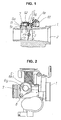
- Fig. 1 is a vertical sectional view showing a first embodiment of a pressure sensor for a fuel injection device in accordance with the present invention;
- Fig. 2 is a plan view of an upper portion in Fig. 1;
- Fig. 3 is an enlarged vertical sectional view of a main portion of a pressure sensor portion in Fig. 1 ;
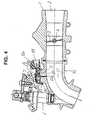
- Fig. 4 is a vertical sectional view showing a second embodiment of the pressure sensor for the fuel injection device in accordance with the present invention;
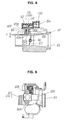
- Fig. 5 is an enlarged vertical cross sectional view of a main portion showing another embodiment of the pressure sensor for the fuel injection device in accordance with the present invention;
- Fig. 6 is a vertical sectional view of a conventional pressure sensor;
- Fig. 7 is a plan view of an upper portion in Fig. 6;
- Fig. 8 is a vertical sectional view showing a state in which the pressure sensor shown in Fig. 6 is installed to a throttle body; and
- Fig. 9 is a plan view of an upper portion in Fig. 8.
- A description will be given below of an embodiment of a pressure sensor for a fuel injection device in accordance with the present invention with reference to the accompanying drawings.
- Fig. 1 is a vertical sectional view of a throttle body provided with a pressure sensor.
- Fig. 2 is a plan view of an upper portion in Fig. 1.
- Fig. 3 is an enlarged vertical sectional view of a main portion of the pressure sensor in Fig. 1.
-
Reference numeral 1 denotes a throttle body in which asuction air passage 2 is provided through in an inner portion. Thesuction air passage 2 is opened and closed by a throttle valve 4 attached to a throttle valve shaft 3. -
Reference numeral 5 denotes a first casing integrally formed in thethrottle body 1. Thefirst casing 5 is structured as follows. -
Reference symbol 5a denotes a cylindrical first tube portion formed in an outer periphery of thethrottle body 1 so as to protrude toward an upper side. A cylindricalsecond tube portion 5b having a smaller diameter than thefirst tube portion 5a is formed so as to protrude toward a further upper side from an upper end of thefirst tube portion 5a. - The
first tube portion 5a and thesecond tube portion 5b form arotation support portion 5c in thefirst casing 5 side. - Further, reference symbol P denotes a negative pressure introduction path directly pierced in the
throttle body 1 corresponding to thefirst casing 5. A lower end thereof is open toward thesuction air passage 2, and an upper end thereof is open to an upper bottom portion 5d of thesecond tube portion 5b. - Further, reference symbol 1a denotes a mounting boss provided uprightly on the
throttle body 1, and reference symbol 1b denotes a female thread hole provided in the mounting boss 1a. -
Reference numeral 6 denotes a cup-shaped second casing arranged so as to face to thefirst casing 5. A secondconcave portion 6b to which thesecond tube portion 5b of thefirst casing 5 is inserted, and a firstconcave portion 6c to which thefirst tube portion 5a of thefirst casing 5 is inserted are continuously provided from an outer periphery of the upper bottom portion 6a toward a lower side. - The first
concave portion 6c and the secondconcave portion 6b form arotation support portion 6d in thesecond casing 6 side. -
Reference symbol 6e denotes a connector portion formed so as to open toward an outer side from therotation support portion 6d of thesecond casing 6. A right end of a terminal 6f out-molded within thesecond casing 6 is arranged within theconnector portion 6e so as to protrude. - Further, a
pressure sensor 62 is fixedly arranged in an inner side of the upper bottom portion 6a of thesecond casing 6, and a terminal 62a extending to a side portion from thepressure sensor 62 is electrically connected to a left end of theterminal 6f out-molded to thesecond casing 6 in accordance with welding or the like. - In the present embodiment, the
pressure sensor 62 is fixedly arranged by a potting material t. - Further,
reference symbol 6g denotes a guide tube portion formed so as to extend to an upper side of the upper bottom portion 6a of thesecond casing 6. Theguide tube portion 6g is coaxially formed with therotation support portion 6d (the firstconcave portion 6c and the secondconcave portion 6b) in thesecond casing 6 side. - Further, the pressure sensor for the fuel injection device is formed as follows.
- First, the
second casing 6, in which thepressure sensor 62 is fixedly arranged in the inner portion, is installed to thethrottle body 1 corresponding to thefirst casing 5, the secondconcave portion 6b of thesecond casing 6 is inserted to the outer periphery of thesecond tube portion 5b of thethrottle body 1, the firstconcave portion 6c of thesecond casing 6 is inserted to the outer periphery of thefirst tube portion 5a of thethrottle body 1, and an elastic ring R such as an O-ring, a square ring or the like made of a rubber material is arranged compressedly within an annular gap S formed between an outer periphery of thesecond tube portion 5b and an inner periphery of the firstconcave portion 6c at this time. - Secondly, a plate-shaped fixing
member 7 is arranged on the upper bottom portion 6a of thesecond casing 6, and afirst guide hole 7a inserting aguide tube portion 6g of thesecond casing 6 and a second guide hole 7b for inserting a screw are provided in the fixingmember 7. - In other words, the fixing
member 7 is arranged on the upper bottom portion 6a of thesecond casing 6, thefirst guide hole 7a is inserted toward theguide tube portion 6g, and ascrew 8 inserted into the second guide hole 7b is screwed toward the female thread hole 1b of thethrottle body 1. - In accordance with the structure mentioned above, the
second casing 6 is pressed and fixed toward thethrottle body 1 by the fixingmember 7. Accordingly, thepressure receiving chamber 9 is formed by the inner portion of the upper bottom portion 6a and the inner portion of the secondconcave portion 6b in thesecond casing 6, and the upper bottom portion 5d of thesecond casing portion 5b corresponding to thefirst casing 5, and thepressure receiving chamber 9 is held by the elastic ring R so as to be airtight with respect to the atmospheric air and is connected with thesuction air passage 2 of thethrottle body 1 by the negative pressure introduction path P. - Further, the
pressure sensor 62 is fixedly arranged within thepressure chamber 9, the terminal 62a of thepressure sensor 62 is electrically connected to the terminal 6f, and a right end thereof is arranged so as to protrude into theconnector portion 6e. - In accordance with the structure mentioned above, the pressure generated within the
suction air passage 2 is introduced into thepressure receiving chamber 9 which is in a sealed state via the negative pressure introduction path P, and thepressure sensor 62 senses the pressure within thepressure receiving chamber 9, and outputs an electric signal in correspondence to the pressure from the terminal 6f. - In accordance with the pressure sensor for the fuel injection device on the basis of the present invention having the structure mentioned above, the
pressure receiving chamber 9 is formed by thesecond casing 6 and thethrottle body 1 corresponding to thefirst casing 5, the negative pressure introduction path P is directly pierced in thethrottle body 1, an upper end thereof is open to an inner side of thepressure receiving chamber 9, and a lower end thereof is open to thesuction air passage 2. - In accordance with the structure mentioned above, an opening Pa of the negative pressure introduction path P to the
suction air passage 2 can be always open at a fixed position. - In other words, it is possible to prevent the opening Pa of the negative pressure introduction path P from protruding to the inner side of the
suction air passage 2 or being concaved from thesuction air passage 2 so as to be open. - In accordance with the structure mentioned above, since it is possible to maintain an eddy current applied to the opening Pa of the negative pressure introduction path P to be constant, it is possible to introduce a stable pressure into the
pressure receiving chamber 9 via the negative pressure introduction path P, whereby it is possible to detect an accurate pressure within thesuction air passage 2. - Further, it is possible to adjust the response speed of the pressure generated in the suction air passage with respect to the
pressure receiving chamber 9 by selecting the hole diameter of the negative pressure introduction path P. - Further, since the negative pressure introduction path P is formed in the
throttle body 1, and a sufficient thickness portion is provided in the periphery thereof, it is possible to freely select the hole diameter of the negative pressure introduction path P. - No limitation is applied to the selection of the large diameter and the selection of the small diameter in the drill diameter.
- Further, the
second casing 6 is rotatably arranged with respect to thethrottle body 1 corresponding to thefirst casing 5, thesecond casing 6 is rotatably moved with respect to thefirst casing 5 so as to be positioned, and then thesecond casing 6 is fixed to thefirst casing 5 by the fixingmember 7 in a state in which thesecond casing 6 is positioned. - In accordance with the structure mentioned above, it is possible to appropriately set the opening position of the
connector portion 6e of thesecond casing 6 to a desired position, and it is possible to provide the pressure sensor having a high general purpose property. - Further, since the rotational movement of the
second casing 6 with respect to thefirst casing 5 is executed by therotation support portion 5c (thesecond tube portion 5b and or thefirst tube portion 5a) in thefirst casing 5 side, and therotation support portion 6d (the secondconcave portion 6b and the firstconcave portion 6c) in thesecond casing 6 side, it is possible to stably support the rotation of thesecond casing 6. - Further, since the elastic ring R for seal is arranged compressedly in the annular gap S formed between the
rotation support portion 5c in thefirst casing 5 side and therotation support portion 6d in thesecond casing 6 side which are arranged so as to be opposed, it is possible to stably keep the airtightness within thepressure receiving chamber 9 at a time when thesecond casing 6 is rotationally moved. - Further, the
guide tube portion 6g is provided so as to protrude on the upper bottom portion 6a of thesecond casing 6, the guide tube portion is coaxially formed with therotation support portion 6d (the secondconcave portion 6b and the firstconcave portion 6c) in thesecond casing 6 side, the fixingmember 7 fixed by screw to thethrottle body 1 is arranged on the upper bottom portion 6a of thesecond casing 6 and thefirst guide hole 7a provided in the fixingmember 7 is arranged so as to be inserted to the outer periphery of theguide tube portion 6g. Accordingly, it is possible to arrange thesecond casing 6 so as to be rotatable with respect to thethrottle body 1 corresponding to thefirst casing 5, and the fixingmember 7 presses the upper bottom portion 6a of thesecond casing 6 by fixing and screwing the fixingmember 7 with respect to thethrottle body 1 by thescrew 8, whereby it is possible to position and fix thesecond casing 6. - In this case, particularly, since the fixing
member 7 is formed in a flat plate shape, and thefirst guide hole 7a and the second guide hole 7b are formed to be simple through holes, it is possible to extremely inexpensively manufacture the fixingmember 7 and the assembly thereof can be achieved by arranging the fixingmember 7 on the upper bottom portion 6a of thesecond casing 6 and screwing it toward thethrottle body 1 by thescrew 8, whereby it is possible to improve a workability. - In this case, the embodiment mentioned above is structured such that the
throttle body 1 is used as thefirst casing 5, however, the structure may be made such that the first casing is provided in thesuction air pipe 10 having the fuel injection valve J and the suction air passage 11, as shown in Fig. 4. - In this case, the same reference numerals are used for the same constituting portions as those in Fig. 1.
- A second embodiment is shown in Fig. 5.
- In the present embodiment, the opening Pb of the negative pressure introduction path P to the inner side of the
pressure receiving chamber 9 is open at an outer side of a transverse projection plane W in a transverse plane orthogonal to a center line X-X of thepressure sensor 62. - In accordance with the present embodiment, when the sudden pressure change is generated within the
suction air passages 2 and 11 due to a backfire or the like, great pressure comes into collision with the wall portion constituting thepressure receiving chamber 9, and is not directly applied to thepressure sensor 62. Accordingly, it is possible to prevent the elements constituting thepressure sensor 62 frombeing broken. - As mentioned above, in accordance with the pressure sensor for the fuel injection device on the basis of the present invention, since the
pressure receiving chamber 9 is formed by thesecond casing 6 and thefirst casing 5, and thefirst casing 5 and the negative pressure introduction path P are formed by thethrottle body 1 or thesuction air pipe 10, it is possible to stably introduce the pressure within thesuction air passages 2 and 11 into thepressure receiving chamber 9. - Further, it is possible to freely change the hole diameter of the negative pressure introduction path P, and it is possible to extremely easily and optionally set the response speed of the pressure with respect to the
pressure receiving chamber 9. - Further, since the
throttle body 1 or thesuction air pipe 10 is utilized as thefirst casing 5, it is possible to achieve a common use of parts, and it is possible to lower a manufacturing cost. - Further, since the
second casing 6 is rotatably arranged with respect to thefirst casing 5, and thesecond casing 6 is fixed to thefirst casing 5 by the fixingmember 7 after positioning thesecond casing 6, it is possible to make the opening of theconnector portion 6e formed in thesecond casing 6 to be open toward an optional position, and it is possible to improve a general purpose property. - Further, since the opening Pb of the negative pressure introduction path P to the
pressure receiving chamber 9 is open to the outer side of the transverse projection plane W orthogonal to the center line X-X of thepressure sensor 62, it is possible to stably use thepressure sensor 62 for a long term.
Claims (5)
- A pressure sensor for a fuel injection device comprising:a pressure receiving chamber formed by a first casing and a second casing;a semiconductor type pressure sensor arranged so as to be contained within said pressure receiving chamber; anda terminal extended out toward an inner side of a connector portion from the pressure sensor,wherein said first casing (5) and a negative pressure introduction path (P) introducing a pressure in a suction air passage (2, 11) into the pressure receiving chamber (9) are integrally formed in a throttle body (1) or a suction air pipe (10).
- A pressure sensor for a fuel injection device as claimed in claim 1, wherein said second casing is rotatably arranged on the throttle body (1) or the suction air pipe (10) constituting the first casing (5), and the second casing (6) is fixedly arranged on the first casing (5) by a fixing member (7) after the second casing (6) being positioned in a rotational direction.
- A pressure sensor for a fuel injection device as claimed in claim 2, wherein an elastic ring (R) for seal is arranged compressedly in opposing rotation support portions (5c, 6d) of said second casing and the first casing.
- A pressure sensor for a fuel injection device as claimed in claim 2, wherein a guide tube portion (6g) coaxially formed with a rotation support portion (6d) of the second casing (6) is provided so as to protrude on an upper bottom portion (6a) of said second casing, and the second casing (6) is fixed to the first casing (5) by screwing a plate corresponding to a fixing member (7), which is inserted to an outer periphery of the guide tube portion (6g) and arranged on an upper bottom portion (6a), to the throttle body (1) or the suction air pipe (10).
- A pressure sensor for a fuel injection device as claimed in claim 1, wherein said negative pressure introduction path is open toward a pressure receiving chamber (9) outside a transverse projection plane orthogonal to a center line (X-X) of the pressure sensor (62).
Applications Claiming Priority (2)
| Application Number | Priority Date | Filing Date | Title |
|---|---|---|---|
| JP2004098554 | 2004-03-30 | ||
| PCT/JP2005/006556 WO2005095776A1 (en) | 2004-03-30 | 2005-03-29 | Pressure sensor for fuel injection device |
Publications (3)
| Publication Number | Publication Date |
|---|---|
| EP1731739A1 true EP1731739A1 (en) | 2006-12-13 |
| EP1731739A4 EP1731739A4 (en) | 2010-12-01 |
| EP1731739B1 EP1731739B1 (en) | 2017-05-10 |
Family
ID=35063840
Family Applications (1)
| Application Number | Title | Priority Date | Filing Date |
|---|---|---|---|
| EP05721696.2A Expired - Lifetime EP1731739B1 (en) | 2004-03-30 | 2005-03-29 | Pressure sensor for fuel injection device |
Country Status (5)
| Country | Link |
|---|---|
| EP (1) | EP1731739B1 (en) |
| JP (1) | JP4546463B2 (en) |
| CN (1) | CN100562656C (en) |
| TW (1) | TWI281023B (en) |
| WO (1) | WO2005095776A1 (en) |
Families Citing this family (7)
| Publication number | Priority date | Publication date | Assignee | Title |
|---|---|---|---|---|
| JP2007192693A (en) * | 2006-01-20 | 2007-08-02 | Keihin Corp | Pressure sensor |
| WO2008001610A1 (en) * | 2006-06-29 | 2008-01-03 | Aisan Kogyo Kabushiki Kaisha | Air intake device for engine |
| JP4818840B2 (en) * | 2006-07-21 | 2011-11-16 | 愛三工業株式会社 | Engine intake system |
| JP2008088937A (en) * | 2006-10-04 | 2008-04-17 | Mitsubishi Electric Corp | Detection device and engine control device |
| JP6399018B2 (en) * | 2016-03-03 | 2018-10-03 | トヨタ自動車株式会社 | Internal combustion engine |
| DE102016219954B3 (en) * | 2016-10-13 | 2018-01-25 | Continental Automotive Gmbh | Method for checking a pressure sensor of a high-pressure injection system, control device, high-pressure injection system and motor vehicle |
| JP7040138B2 (en) | 2018-03-06 | 2022-03-23 | 株式会社アイシン | Intake device |
Family Cites Families (14)
| Publication number | Priority date | Publication date | Assignee | Title |
|---|---|---|---|---|
| JPS6081234U (en) * | 1983-11-08 | 1985-06-05 | 愛三工業株式会社 | Sensor mounting structure in electronically controlled fuel injection device |
| JP2732665B2 (en) * | 1988-07-08 | 1998-03-30 | 株式会社日本自動車部品総合研究所 | Intake pipe pressure detector |
| JPH07279705A (en) * | 1994-04-06 | 1995-10-27 | Daihatsu Motor Co Ltd | Sensor installation structure |
| US5412994A (en) * | 1994-06-14 | 1995-05-09 | Cook; James D. | Offset pressure sensor |
| JPH08261080A (en) * | 1995-03-28 | 1996-10-08 | Mikuni Corp | Throttle body pressure introduction passage structure |
| DE19517676B4 (en) * | 1995-05-13 | 2008-01-31 | Robert Bosch Gmbh | Pressure sensor for an internal combustion engine with an intake pipe |
| JP3693074B2 (en) * | 1996-03-27 | 2005-09-07 | スズキ株式会社 | Intake pressure detector |
| JPH10141112A (en) * | 1996-11-08 | 1998-05-26 | Aisan Ind Co Ltd | Intake pressure measuring device |
| DE19813756A1 (en) * | 1998-03-27 | 1999-10-07 | Siemens Ag | Fluid pressure measuring method |
| JP3532776B2 (en) * | 1998-10-20 | 2004-05-31 | 株式会社日立製作所 | Mounting structure for automotive sensors |
| JP4281200B2 (en) * | 1999-10-07 | 2009-06-17 | 株式会社デンソー | Pressure detection device |
| JP2001124652A (en) * | 1999-10-26 | 2001-05-11 | Denso Corp | Pressure sensor |
| DE10006657A1 (en) * | 2000-02-15 | 2001-08-23 | Siemens Ag | Pressure sensor device |
| DE10228000A1 (en) * | 2002-06-22 | 2004-01-08 | Robert Bosch Gmbh | Pressure measuring device |
-
2005
- 2005-03-28 TW TW94109538A patent/TWI281023B/en not_active IP Right Cessation
- 2005-03-29 CN CNB2005800105163A patent/CN100562656C/en not_active Expired - Lifetime
- 2005-03-29 JP JP2006511856A patent/JP4546463B2/en not_active Expired - Lifetime
- 2005-03-29 WO PCT/JP2005/006556 patent/WO2005095776A1/en not_active Ceased
- 2005-03-29 EP EP05721696.2A patent/EP1731739B1/en not_active Expired - Lifetime
Also Published As
| Publication number | Publication date |
|---|---|
| EP1731739B1 (en) | 2017-05-10 |
| JP4546463B2 (en) | 2010-09-15 |
| CN1938504A (en) | 2007-03-28 |
| TWI281023B (en) | 2007-05-11 |
| TW200537084A (en) | 2005-11-16 |
| WO2005095776A1 (en) | 2005-10-13 |
| JPWO2005095776A1 (en) | 2007-08-16 |
| EP1731739A4 (en) | 2010-12-01 |
| CN100562656C (en) | 2009-11-25 |
Similar Documents
| Publication | Publication Date | Title |
|---|---|---|
| KR100327879B1 (en) | Gas supply equipment with pressure type flow rate control device | |
| US7934419B2 (en) | Intake air mass flow measurement device | |
| US9921121B2 (en) | Pressure measuring instrument | |
| EP1731739B1 (en) | Pressure sensor for fuel injection device | |
| JP2008309623A (en) | Air flow measurement device | |
| WO2019106960A1 (en) | Valve, method for diagnosing abnormality of valve, and computer program | |
| JP7189631B2 (en) | Fluid control equipment | |
| CN105745521A (en) | Pressure sensor arrangement for detecting a pressure of a fluid medium in a measurement chamber | |
| JP2003329495A (en) | Air flow measuring device and its mounting structure | |
| CN107532935B (en) | Sensor for determining at least one parameter of a fluid medium flowing through a measurement channel | |
| US6550338B1 (en) | Pressure sensing device | |
| CN118442446A (en) | Flow regulating device and mass flow controller | |
| CN113685581A (en) | Modularized gas flow path distribution device | |
| JP3797325B2 (en) | Sensor mounting device | |
| WO2004083618A1 (en) | Throttle body | |
| JP2002022049A (en) | Motor valve | |
| JP2019052948A (en) | Pressure temperature sensor | |
| US20090260448A1 (en) | Apparatus for Measuring Pressure by Using Diaphragm and Method of Pressure Measurement by Using Diaphragm | |
| JP2004132698A (en) | Differential pressure / absolute pressure converter for load lock control | |
| JPH09329473A (en) | Gas flow rate measuring device | |
| JP2000346682A (en) | Flow rate detection mechanism | |
| CN220556054U (en) | mass flow controller | |
| JP3160345U (en) | Flow control unit | |
| CN220569089U (en) | Flow controller | |
| TWI880179B (en) | Airflow controlling assembly, and sensing and controlling module of airflow for an active aerosol suction device |
Legal Events
| Date | Code | Title | Description |
|---|---|---|---|
| PUAI | Public reference made under article 153(3) epc to a published international application that has entered the european phase |
Free format text: ORIGINAL CODE: 0009012 |
|
| 17P | Request for examination filed |
Effective date: 20060928 |
|
| AK | Designated contracting states |
Kind code of ref document: A1 Designated state(s): DE FR GB |
|
| DAX | Request for extension of the european patent (deleted) | ||
| RBV | Designated contracting states (corrected) |
Designated state(s): DE FR GB |
|
| A4 | Supplementary search report drawn up and despatched |
Effective date: 20101104 |
|
| RIC1 | Information provided on ipc code assigned before grant |
Ipc: G01L 23/24 20060101ALI20101028BHEP Ipc: F02D 35/00 20060101AFI20051020BHEP Ipc: F02M 35/10 20060101ALI20101028BHEP |
|
| 17Q | First examination report despatched |
Effective date: 20121022 |
|
| GRAP | Despatch of communication of intention to grant a patent |
Free format text: ORIGINAL CODE: EPIDOSNIGR1 |
|
| INTG | Intention to grant announced |
Effective date: 20161102 |
|
| GRAS | Grant fee paid |
Free format text: ORIGINAL CODE: EPIDOSNIGR3 |
|
| GRAA | (expected) grant |
Free format text: ORIGINAL CODE: 0009210 |
|
| STAA | Information on the status of an ep patent application or granted ep patent |
Free format text: STATUS: THE PATENT HAS BEEN GRANTED |
|
| AK | Designated contracting states |
Kind code of ref document: B1 Designated state(s): DE FR GB |
|
| REG | Reference to a national code |
Ref country code: GB Ref legal event code: FG4D |
|
| REG | Reference to a national code |
Ref country code: DE Ref legal event code: R096 Ref document number: 602005051912 Country of ref document: DE |
|
| REG | Reference to a national code |
Ref country code: DE Ref legal event code: R097 Ref document number: 602005051912 Country of ref document: DE |
|
| PLBE | No opposition filed within time limit |
Free format text: ORIGINAL CODE: 0009261 |
|
| STAA | Information on the status of an ep patent application or granted ep patent |
Free format text: STATUS: NO OPPOSITION FILED WITHIN TIME LIMIT |
|
| 26N | No opposition filed |
Effective date: 20180213 |
|
| GBPC | Gb: european patent ceased through non-payment of renewal fee |
Effective date: 20180329 |
|
| PG25 | Lapsed in a contracting state [announced via postgrant information from national office to epo] |
Ref country code: GB Free format text: LAPSE BECAUSE OF NON-PAYMENT OF DUE FEES Effective date: 20180329 |
|
| PG25 | Lapsed in a contracting state [announced via postgrant information from national office to epo] |
Ref country code: FR Free format text: LAPSE BECAUSE OF NON-PAYMENT OF DUE FEES Effective date: 20180331 |
|
| REG | Reference to a national code |
Ref country code: DE Ref legal event code: R081 Ref document number: 602005051912 Country of ref document: DE Owner name: HITACHI ASTEMO, LTD., HITACHINAKA-SHI, JP Free format text: FORMER OWNER: KEIHIN CORPORATION, TOKYO, JP |
|
| PGFP | Annual fee paid to national office [announced via postgrant information from national office to epo] |
Ref country code: DE Payment date: 20240130 Year of fee payment: 20 |
|
| REG | Reference to a national code |
Ref country code: DE Ref legal event code: R071 Ref document number: 602005051912 Country of ref document: DE |