EP1731406A2 - Electric power steering unit and controller thereof - Google Patents
Electric power steering unit and controller thereof Download PDFInfo
- Publication number
- EP1731406A2 EP1731406A2 EP06011862A EP06011862A EP1731406A2 EP 1731406 A2 EP1731406 A2 EP 1731406A2 EP 06011862 A EP06011862 A EP 06011862A EP 06011862 A EP06011862 A EP 06011862A EP 1731406 A2 EP1731406 A2 EP 1731406A2
- Authority
- EP
- European Patent Office
- Prior art keywords
- controller
- terminal
- power steering
- electric power
- steering unit
- Prior art date
- Legal status (The legal status is an assumption and is not a legal conclusion. Google has not performed a legal analysis and makes no representation as to the accuracy of the status listed.)
- Withdrawn
Links
Images





Classifications
-
- H—ELECTRICITY
- H01—ELECTRIC ELEMENTS
- H01R—ELECTRICALLY-CONDUCTIVE CONNECTIONS; STRUCTURAL ASSOCIATIONS OF A PLURALITY OF MUTUALLY-INSULATED ELECTRICAL CONNECTING ELEMENTS; COUPLING DEVICES; CURRENT COLLECTORS
- H01R4/00—Electrically-conductive connections between two or more conductive members in direct contact, i.e. touching one another; Means for effecting or maintaining such contact; Electrically-conductive connections having two or more spaced connecting locations for conductors and using contact members penetrating insulation
- H01R4/28—Clamped connections, spring connections
- H01R4/30—Clamped connections, spring connections utilising a screw or nut clamping member
- H01R4/34—Conductive members located under head of screw
-
- B—PERFORMING OPERATIONS; TRANSPORTING
- B62—LAND VEHICLES FOR TRAVELLING OTHERWISE THAN ON RAILS
- B62D—MOTOR VEHICLES; TRAILERS
- B62D5/00—Power-assisted or power-driven steering
- B62D5/04—Power-assisted or power-driven steering electrical, e.g. using an electric servo-motor connected to, or forming part of, the steering gear
- B62D5/0403—Power-assisted or power-driven steering electrical, e.g. using an electric servo-motor connected to, or forming part of, the steering gear characterised by constructional features, e.g. common housing for motor and gear box
Definitions
- the present invention relates to an electric power steering unit and a controller thereof. More specifically, the present invention relates to improvements in the structure of connecting a harness of an electric motor, which is a drive source of an electric power steering unit, to a controller.
- this electric power steering unit includes: a torque sensor for detecting a steering torque given to a steered wheel; and an electric motor for assisting a driver when the driver conducts steering operation.
- This electric power steering unit drives the electric motor according to a steering torque detected by the torque sensor.
- a rotational output of the electric motor becomes an assisting steering torque.
- a rotational speed of this rotational output of the electric motor is reduced by a gear mechanism and transmitted to an output shaft of a steering mechanism. Due to the foregoing, while a steering force given to the steering wheel is being assisted, a steering operation is conducted on the vehicle.
- a controller In order to control this electric power steering unit, a controller is mounted on a vehicle.
- This controller includes an electric control circuit (a circuit such as CPU, referred to as ECU) which receives a steering torque signal sent from the torque sensor and also receives signals sent from various sensors and processes these signals with a predetermined algorithm. According to the result of processing conducted by the electric control circuit, a drive current supplied from an electric power source to the electric motor is controlled.
- ECU electric control circuit
- Patent Document 1 shows an example of the electric power steering circuit unit.
- the circuit unit (ECU) which is made up of a conductive plate, on which wiring is provided, a connector is arranged, and the wiring (harness) of the electric circuit and the wiring (harness) of the electric motor are connected to each other via this connector. Due to this structure, it becomes possible to increase an intensity of the electric current capable of being supplied to the electric motor.
- Patent Document 1 JP-A-2003-26010
- an engagement direction (a connecting direction) at the time of connecting the terminal of the harness of the electric motor to the connector is limited to an inserting direction of inserting the terminal into the connector. Therefore, an arranging direction and an arranging position of the electric motor of the electric power steering unit in the vehicle are restricted. Accordingly, a degree of freedom of designing the layout of the electric power steering unit is low, and it takes time to conduct designing the electric power steering unit. Further, a layout of another device becomes too tight when it is designed.
- An object of the present invention is to provide an electric power steering unit characterized in that: a contact resistance at a connecting portion between a lead wire of an electric motor and an electric control circuit (ECU) is positively controlled so that a high intensity of electric current can be made to flow and a high voltage can be impressed; and a degree of freedom of designing a layout of the electric power steering unit in a vehicle can be enhanced.
- ECU electric control circuit
- the present invention provides an electric power steering unit including: an electric motor for driving an electric power steering unit of a vehicle; a controller for controlling a drive of the electric motor; and a bolt-fastening type connecting section arranged in the controller, constituting a signal terminal of the controller, wherein a terminal of a harness extending from the electric motor is fastened to the connecting section by means of bolt-fastening.
- a controller used for an electric power steering unit which controls a drive of an electric motor to be used as a drive source of driving an electric power steering unit of a vehicle.
- This controller includes a terminal base provided integrally with the controller, having a connecting section of a bolt-fastening structure constituting a signal terminal of the controller, wherein a terminal of the harness extending from the electric motor is fastened to the connecting section by means of bolt-fastening.
- the electric power steering unit and the controller thereof of the present invention it is possible to positively control a contact resistance at a connecting portion of the lead wire of the electric motor to the controller so that a high intensity of electric current can made to flow in the electric power steering unit and a high voltage can be impressed upon the electric power steering unit. Further, it is possible to enhance a degree of freedom of designing a layout of the electric power steering unit in a vehicle.
- this electric power steering unit includes: a steering wheel 2; a steering mechanism 3 interposed between a right and a left steered wheel DW, DW; and a controller (ECU) 4 for controlling a generation of a steering force from this steering mechanism 3.
- ECU controller
- the steering mechanism 3 includes: a steering shaft 11 connected to the steering wheel 2; an intermediate shaft 12; a reduction gear 13 interposed between the steering shaft 11 and the intermediate shaft 12; a gear 14 connected between the intermediate shaft 12 and steered wheels DW, DW; and a rack 15 connected between the intermediate shaft 12 and steered wheels DW, DW.
- An output shaft 16A of a three-phase AC electric motor 16, which is the electric motor described above, is also meshed with the reduction gear 13.
- the electric motor 16 is driven when it receives a command (a drive current) from the controller 4. When the electric motor 16 is driven in this way, an assisting steering force is given to the steering mechanism 3.
- a steering force given to the steering wheel 2 is transmitted to the reduction gear 13 via the steering shaft 11.
- the reduction gear 13 includes a reduction mechanism not shown in the drawing. Therefore, although not shown in the drawing, the reduction gear 13 changes a rotational direction of the output from the output shaft 16A of the electric motor 16 into a direction perpendicular to the direction concerned, and while the reduction gear 13 is reducing a rotational speed of the output from the output shaft 16A of the electric motor 16, it generates an assisting torque.
- the thus generated assisting torque is added to the steering torque and transmitted to the intermediate shaft 12. Therefore, the assisting torque, which is based on the electric motor 16, is given to the steered wheels DW, DW. In this way, an assisting steering force can be given by the electric motor 16.
- the controller 4 receives a signal from a torque sensor (not shown) for detecting a steering force. Further, the controller 4 receives pieces of information such as a steering angle and a vehicle running speed which express a state of a running vehicle. According to these pieces of information, a desired assisting force is calculated at a predetermined time, and a drive current for generating the rotational direction and the rotational torque corresponding to the assisting steering force is supplied to the electric motor 16. Due to the foregoing, a manual steering force of a driver, which is given to the steering wheel 2, is assisted in the viewpoint of torque. The thus assisted steering force is transmitted to the steered wheels DW, DW. In this way, a function of the electric power steering unit can be exhibited.
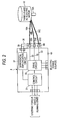
- Fig. 2 is a view showing an outline of the function of the above controller 4 and also showing an electrical connection between the controller 4 and the three phase AC electric motor 16.
- the controller 4 includes: a control circuit 21 made up of a micro-computer (CPU); and a drive circuit 22 for generating a drive current corresponding to a control command calculated by this control circuit 21.
- a control circuit 21 made up of a micro-computer (CPU)
- a drive circuit 22 for generating a drive current corresponding to a control command calculated by this control circuit 21.
- control circuit 21 pieces of information related to a steering torque and a running state of a vehicle are sent from various sensors not shown. Therefore, the control circuit 21 starts a program, which is previously stored, and processes the thus inputted information according to an algorithm for assisting a steering force given by the program. The result of the processing is sent to the drive circuit 22 at a predetermined time. This result of the processing is obtained as a duty ratio for switching an electric power source supplied to the drive circuit 22. Therefore, the drive circuit 22 generates a drive current for driving the electric motor 16 on the basis of the control conducted by the control circuit 21.
- the controller 4 includes a board 4A on which the control circuit 21 and the drive circuit 22 are mounted. At one end portion of this board 4A, a terminal base 4B functioning as a connecting section with the electric motor 16 is fixed. On this terminal base 4B, three output terminals 23A to 23C, which are fastened by bolts, are formed. In this connection, the terminal base 4B and the internal circuit of the controller 4 may be connected to each other by either a harness, a circuit board or one conductive sheet made by means of press forming.
- each of the output terminals 23A to 23C can fasten a terminal, which is provided from the outside, with a bolt 31 and a nut 32.
- An electric wire 33 which is used for supplying an electric current from the drive circuit 22, is connected to each of the output terminals 23A to 23C.
- terminal TN of each of the three pieces of the harness 16A to 16C which extend from the electric motor 16, can be fastened by the bolt 31 and the nut 32 via a washer 34.
- an elliptical hole TNh used for connection is formed as shown in Fig. 4.
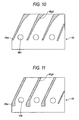
- positioning guides 4Bg1, 4Bg2, 4Bg3, 4Bg4 for regulating movements of the pieces of harness 16A to 16C are provided on the bulkheads 4Bw of the terminal base 4B as shown in Figs. 8 to 11.
- the positioning guides 4Bg1 regulate movements of the pieces of harness 16A to 16C in the width direction. Therefore, the pieces of harness 16A to 16C can be easily assembled to the terminal base 4B.
- the positioning guides 4Bg2 regulate movements of the terminals TN, which are fixed to the forward end portions of the pieces of harness 16A to 16C, in the width direction. Therefore, the pieces of harness 16A to 16C can be easily assembled to the terminal base 4B.
- the positioning guides 4Bg3, 4Bg4 respectively function as bulkheads and are obliquely formed on the terminal base 4B. Therefore, the positioning guides 4Bg3, 4Bg4 respectively regulate movements of the pieces of harness 16A to 16C in the width direction. Accordingly, the pieces of harness 16A to 16C can be easily assembled to the terminal base 4B.
- the positioning guides 4Bgl to 4Bg4 are provided on the terminal base 4B, the worker can conduct working with one hand. Therefore, it is possible to reduce the working time.
- the electric motor 16 can be electrically connected to the drive circuit 22. Due to this structure, a drive current outputted from the drive circuit 22 is sent to the electric motor 16 and an assisting steering torque can be given to the steered wheels DW, DW as described before.
- the present embodiment further includes a function of controlling a contact resistance in the output terminals 23A to 23C.
- An object of controlling the contact resistance is to positively prevent the occurrence of problems such as heating, melting, smoking and igniting. In order to realize the prevention of these problems, it is necessary to provide a mechanism for detecting the contact resistance.
- This embodiment includes: lead wires 35, 36, the detecting end portions of which are electrically connected to core wire portions of the pieces of harness 16a to 16C and also connected to the output terminals 23A to 23C; and a differential amplification circuit 37 to which these lead wires 35, 36 are connected.
- the differential amplification circuit 37 is mounted in the controller 4 and detects and amplifies a voltage difference between both the detection end portions, and the thus obtained difference signal is sent out to the control circuit 21.
- Fig. 2 shows only the differential amplification circuit 37 which corresponds to only one output terminal 23A. However, it is preferable that the differential amplification circuits 37 are separately provided for all the output terminals 23A to 23C. Of course, depending upon a case, only one terminal may be provided with the differential amplification circuit 37 as shown in the drawing.
- the control circuit 21 which receives a signal from the differential amplification circuit 37, controls the drive circuit 22 so that a restricting function for restricting a drive current to be supplied to the electric motor 16 can be obtained.
- the temperature detection member 41 such as a thermistor may be provided in all the output terminals 23A to 23C or in one portion of the output terminals 23A to 23C.
- the reason why the temperature detection member 41 is provided is that when a contact resistance between each output terminal 23A to 23C and each terminal TN of the harness 16a to 16C is increased, the increase is reflected in the temperature. Therefore, after a detection signal of the temperature detection member 41 has been sent out to the input circuit 42 and amplified, it is sent to the control circuit 21.
- control circuit 21 compares the detection signal with a predetermined threshold value and the detection signal is higher than the threshold value, in the same manner as that described before, a restricting function of restricting the drive current sent to the electric motor 16 is exhibited. Due to the foregoing, an increase in the contact resistance of each output terminal 23A to 23C can be always watched in real time. When necessary, a predetermined countermeasure can be quickly and positively taken, for example, an intensity of the electric current can be restricted.
- the pieces of harness 16A to 16C of the electric motor 16 are connected to the terminal base 4B of the controller 4 by means of fastening bolts, the following various advantages can be provided.
- the present invention provides an electric power steering unit in which an intensity of the drive current can be increased and further a heat deterioration can be suppressed.
- an intensity of the drive current supplied to the electric motor of the electric power steering unit must be increased and further a higher voltage must be impressed upon the electric power steering unit.
- the connecting method of the prior art in which the conventional connector is used, when a contact failure is caused in the engaging portion (the connecting portion) of the connector, heat deterioration tends to be caused by the contact resistance. Accordingly, there is a possibility that the durability of the connector is lowered.
- the electric power steering unit 1 of the present embodiment the above problems of the prior art can be solved.
- the present invention can positively cope with the case of a heavy vehicle in which it is necessary to supply a high intensity of current and further it is necessary to impress a higher voltage. Accordingly, the steering torque assisting function can be more positively and stably exhibited.
- the aforementioned advantages can be provided to not only a heavy vehicle but also a light vehicle.
- a contact resistance is controlled as described above, it is possible to prevent the occurrence of heating, melting, smoking and igniting of the connecting section (the terminal base 4B).
- the connection is made by fastening bolts as described above, it is possible to change an engaging direction (a connecting direction) of each terminal TN of the harness 16A to 16C in a predetermined range. Accordingly, the electric power steering unit 1 can have a sufficient space for accommodating the electric motor 16 and further the electric power steering unit 1 can have a wide arrangement direction for arranging the electric motor 16. Further, it is possible to enhance a degree of freedom of designing a layout of the electric power steering unit 1. Therefore, the layout can be easily designed. Further, the other devices can be easily laid out.
- the controller 4 and the electric motor 16 can be laid out close to each other, and lengths of the pieces of harness 16A to 16C can be shortened. According to this arrangement in which the components are arranged close to each other, radiation noise radiated from the pieces of harness 16A to 16C can be reduced.
Landscapes
- Engineering & Computer Science (AREA)
- Chemical & Material Sciences (AREA)
- Combustion & Propulsion (AREA)
- Transportation (AREA)
- Mechanical Engineering (AREA)
- Power Steering Mechanism (AREA)
- Motor Or Generator Frames (AREA)
Abstract
Description
- The present invention relates to an electric power steering unit and a controller thereof. More specifically, the present invention relates to improvements in the structure of connecting a harness of an electric motor, which is a drive source of an electric power steering unit, to a controller.
- Recently, many of vehicles are equipped with an electric power steering (EPC) unit. In general, this electric power steering unit includes: a torque sensor for detecting a steering torque given to a steered wheel; and an electric motor for assisting a driver when the driver conducts steering operation. This electric power steering unit drives the electric motor according to a steering torque detected by the torque sensor. A rotational output of the electric motor becomes an assisting steering torque. A rotational speed of this rotational output of the electric motor is reduced by a gear mechanism and transmitted to an output shaft of a steering mechanism. Due to the foregoing, while a steering force given to the steering wheel is being assisted, a steering operation is conducted on the vehicle.
- In order to control this electric power steering unit, a controller is mounted on a vehicle. This controller includes an electric control circuit (a circuit such as CPU, referred to as ECU) which receives a steering torque signal sent from the torque sensor and also receives signals sent from various sensors and processes these signals with a predetermined algorithm. According to the result of processing conducted by the electric control circuit, a drive current supplied from an electric power source to the electric motor is controlled.
- In this case, for example, as shown in Patent Document 1, the electric control circuit and the electric motor are connected to each other. To be specific, this Patent Document 1 shows an example of the electric power steering circuit unit. As shown in Fig. 1 of Patent Document 1, in the circuit unit (ECU), which is made up of a conductive plate, on which wiring is provided, a connector is arranged, and the wiring (harness) of the electric circuit and the wiring (harness) of the electric motor are connected to each other via this connector. Due to this structure, it becomes possible to increase an intensity of the electric current capable of being supplied to the electric motor.
- Patent Document 1:
JP-A-2003-26010 - However, in the case where the harness of the electric motor is connected to the connector of the electric control circuit (ECU) so as to increase an intensity of the electric current, the following problems may be encountered. When a connection of the connector is in an incomplete state such as a contact failure, the contact resistance is increased and the heat deterioration is accelerated. This causes a reduction in the durability of the connector. Further, the reliability is deteriorated. Especially in the case of a heavy vehicle, it is necessary to increase an intensity of the drive current and further it is necessary to use a higher voltage. Accordingly, a special importance is attached to the above problems of heat deterioration.
- In the case of the above connection structure, an engagement direction (a connecting direction) at the time of connecting the terminal of the harness of the electric motor to the connector is limited to an inserting direction of inserting the terminal into the connector. Therefore, an arranging direction and an arranging position of the electric motor of the electric power steering unit in the vehicle are restricted. Accordingly, a degree of freedom of designing the layout of the electric power steering unit is low, and it takes time to conduct designing the electric power steering unit. Further, a layout of another device becomes too tight when it is designed.
- The present invention has been accomplished to solve the above problems of the prior art. An object of the present invention is to provide an electric power steering unit characterized in that: a contact resistance at a connecting portion between a lead wire of an electric motor and an electric control circuit (ECU) is positively controlled so that a high intensity of electric current can be made to flow and a high voltage can be impressed; and a degree of freedom of designing a layout of the electric power steering unit in a vehicle can be enhanced.
- In order to accomplish the above object, the present invention provides an electric power steering unit including: an electric motor for driving an electric power steering unit of a vehicle; a controller for controlling a drive of the electric motor; and a bolt-fastening type connecting section arranged in the controller, constituting a signal terminal of the controller, wherein a terminal of a harness extending from the electric motor is fastened to the connecting section by means of bolt-fastening.
- In order to accomplish the above object, a controller used for an electric power steering unit is provided which controls a drive of an electric motor to be used as a drive source of driving an electric power steering unit of a vehicle. This controller includes a terminal base provided integrally with the controller, having a connecting section of a bolt-fastening structure constituting a signal terminal of the controller, wherein a terminal of the harness extending from the electric motor is fastened to the connecting section by means of bolt-fastening.
- According to the electric power steering unit and the controller thereof of the present invention, it is possible to positively control a contact resistance at a connecting portion of the lead wire of the electric motor to the controller so that a high intensity of electric current can made to flow in the electric power steering unit and a high voltage can be impressed upon the electric power steering unit. Further, it is possible to enhance a degree of freedom of designing a layout of the electric power steering unit in a vehicle.
-
- Fig. 1 is a view showing an outline of the structure of the electric power steering unit of an embodiment of the present invention.
- Fig. 2 is a block diagram showing an outline of the structure of the controller employed in an embodiment.
- Fig. 3 is a side view showing a connection between a controller and a harness of an electric motor.
- Fig. 4 is a view for explaining a harness terminal.
- Fig. 5 is a view for explaining a relation between a hole position of a terminal base and a hole position of a harness.
- Fig. 6 is a view for explaining a method of attaching a harness to a terminal base with fittings.
- Figs. 7A and 7B are views for explaining a generation of a positional shift between a terminal base hole and a harness terminal hole.
- Fig. 8 is a plan view of a terminal base in the case where a positioning guide is provided on the terminal base.
- Fig. 9 is a plan view of a terminal base in the case where a positioning guide is provided on the terminal base.
- Fig. 10 is a plan view of a terminal base in the case where a positioning guide is provided on the terminal base.
- Fig. 11 is a plan view of a terminal base in the case where a positioning guide is provided on the terminal base.
- Fig. 12 is a block diagram showing an outline of a structure of a controller employed in a variation.
- Referring to Figs. 1 to 11, explanations will be made into an embodiment of the electric power steering unit and the controller thereof of the present invention.
- As shown in Fig. 1, this electric power steering unit includes: a
steering wheel 2; asteering mechanism 3 interposed between a right and a left steered wheel DW, DW; and a controller (ECU) 4 for controlling a generation of a steering force from thissteering mechanism 3. - The
steering mechanism 3 includes: asteering shaft 11 connected to thesteering wheel 2; anintermediate shaft 12; areduction gear 13 interposed between thesteering shaft 11 and theintermediate shaft 12; agear 14 connected between theintermediate shaft 12 and steered wheels DW, DW; and arack 15 connected between theintermediate shaft 12 and steered wheels DW, DW. Anoutput shaft 16A of a three-phase ACelectric motor 16, which is the electric motor described above, is also meshed with thereduction gear 13. Theelectric motor 16 is driven when it receives a command (a drive current) from thecontroller 4. When theelectric motor 16 is driven in this way, an assisting steering force is given to thesteering mechanism 3. - A steering force given to the
steering wheel 2 is transmitted to thereduction gear 13 via thesteering shaft 11. Thereduction gear 13 includes a reduction mechanism not shown in the drawing. Therefore, although not shown in the drawing, thereduction gear 13 changes a rotational direction of the output from theoutput shaft 16A of theelectric motor 16 into a direction perpendicular to the direction concerned, and while thereduction gear 13 is reducing a rotational speed of the output from theoutput shaft 16A of theelectric motor 16, it generates an assisting torque. The thus generated assisting torque is added to the steering torque and transmitted to theintermediate shaft 12. Therefore, the assisting torque, which is based on theelectric motor 16, is given to the steered wheels DW, DW. In this way, an assisting steering force can be given by theelectric motor 16. - The
controller 4 receives a signal from a torque sensor (not shown) for detecting a steering force. Further, thecontroller 4 receives pieces of information such as a steering angle and a vehicle running speed which express a state of a running vehicle. According to these pieces of information, a desired assisting force is calculated at a predetermined time, and a drive current for generating the rotational direction and the rotational torque corresponding to the assisting steering force is supplied to theelectric motor 16. Due to the foregoing, a manual steering force of a driver, which is given to thesteering wheel 2, is assisted in the viewpoint of torque. The thus assisted steering force is transmitted to the steered wheels DW, DW. In this way, a function of the electric power steering unit can be exhibited. - Fig. 2 is a view showing an outline of the function of the
above controller 4 and also showing an electrical connection between thecontroller 4 and the three phase ACelectric motor 16. - As shown in Fig. 2, the
controller 4 includes: a control circuit 21 made up of a micro-computer (CPU); and adrive circuit 22 for generating a drive current corresponding to a control command calculated by this control circuit 21. - In the control circuit 21, pieces of information related to a steering torque and a running state of a vehicle are sent from various sensors not shown. Therefore, the control circuit 21 starts a program, which is previously stored, and processes the thus inputted information according to an algorithm for assisting a steering force given by the program. The result of the processing is sent to the
drive circuit 22 at a predetermined time. This result of the processing is obtained as a duty ratio for switching an electric power source supplied to thedrive circuit 22. Therefore, thedrive circuit 22 generates a drive current for driving theelectric motor 16 on the basis of the control conducted by the control circuit 21. - The
controller 4 includes aboard 4A on which the control circuit 21 and thedrive circuit 22 are mounted. At one end portion of thisboard 4A, aterminal base 4B functioning as a connecting section with theelectric motor 16 is fixed. On thisterminal base 4B, threeoutput terminals 23A to 23C, which are fastened by bolts, are formed. In this connection, theterminal base 4B and the internal circuit of thecontroller 4 may be connected to each other by either a harness, a circuit board or one conductive sheet made by means of press forming. - As shown in Fig. 3, each of the
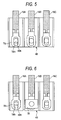
output terminals 23A to 23C can fasten a terminal, which is provided from the outside, with abolt 31 and anut 32. Anelectric wire 33, which is used for supplying an electric current from thedrive circuit 22, is connected to each of theoutput terminals 23A to 23C. On the other hand, terminal TN of each of the three pieces of theharness 16A to 16C, which extend from theelectric motor 16, can be fastened by thebolt 31 and thenut 32 via awasher 34. In each terminal TN of each of the three pieces ofharness 16A to 16C, an elliptical hole TNh used for connection is formed as shown in Fig. 4. Due to this structure, even when theharness 16A to 16C is thick, it is possible to absorb the fluctuation and positively fasten the bolt. In this case, when a circular hole is formed instead of the elliptical hole TNh, a positional shift tends to be caused between this circular hole and the hole formed in theterminal base 4B. Accordingly, a worker is forced to conduct working with both hands, which requires a long working time. On the other hand, as shown in Fig. 5, in the case where the elliptical hole TNh is formed in the terminal TN, a positional shift is seldom caused the elliptical hole TNh and the hole 4Bh formed on theterminal base 4B. Accordingly, it is possible to absorb an attaching tolerance of attaching theharness 16A to 16C to theterminal base 4B. Therefore, it is possible for the worker to conduct working with one hand, and the working time can be reduced. As shown in Fig. 6, when thefittings 39 are fastened simultaneously when theterminal base 4B and theharness 16A to 16C are fastened to each other with bolts, the generation of a positional shift between the elliptical hole TNh and the hole 4Bh can be reduced. Further, theterminal base 4B and theharness 16A to 16C can be positively connected to each other. - In the case where the pieces of
harness 16A to 16C are attached to theterminal base 4B, since a gap is formed between each piece ofharness 16A to 16C and the bulkhead 4Bw of theterminal base 4B as shown in Fig. 7A, there is a possibility that a positional shift is caused between the elliptical hole TNh of the terminal TN and the hole 4Bh of theterminal base 4B as shown in Fig. 7B. - Therefore, in the present embodiment, positioning guides 4Bg1, 4Bg2, 4Bg3, 4Bg4 for regulating movements of the pieces of
harness 16A to 16C are provided on the bulkheads 4Bw of theterminal base 4B as shown in Figs. 8 to 11. The positioning guides 4Bg1 regulate movements of the pieces ofharness 16A to 16C in the width direction. Therefore, the pieces ofharness 16A to 16C can be easily assembled to theterminal base 4B. The positioning guides 4Bg2 regulate movements of the terminals TN, which are fixed to the forward end portions of the pieces ofharness 16A to 16C, in the width direction. Therefore, the pieces ofharness 16A to 16C can be easily assembled to theterminal base 4B. The positioning guides 4Bg3, 4Bg4 respectively function as bulkheads and are obliquely formed on theterminal base 4B. Therefore, the positioning guides 4Bg3, 4Bg4 respectively regulate movements of the pieces ofharness 16A to 16C in the width direction. Accordingly, the pieces ofharness 16A to 16C can be easily assembled to theterminal base 4B. When the positioning guides 4Bgl to 4Bg4 are provided on theterminal base 4B, the worker can conduct working with one hand. Therefore, it is possible to reduce the working time. - Therefore, when three pieces of
harness 16A to 16C are respectively fastened to theoutput terminals 23A to 23C with bolts, theelectric motor 16 can be electrically connected to thedrive circuit 22. Due to this structure, a drive current outputted from thedrive circuit 22 is sent to theelectric motor 16 and an assisting steering torque can be given to the steered wheels DW, DW as described before. - Concerning the connection structure described above, the present embodiment further includes a function of controlling a contact resistance in the
output terminals 23A to 23C. An object of controlling the contact resistance is to positively prevent the occurrence of problems such as heating, melting, smoking and igniting. In order to realize the prevention of these problems, it is necessary to provide a mechanism for detecting the contact resistance. - This embodiment includes: lead
wires output terminals 23A to 23C; and adifferential amplification circuit 37 to which theselead wires differential amplification circuit 37 is mounted in thecontroller 4 and detects and amplifies a voltage difference between both the detection end portions, and the thus obtained difference signal is sent out to the control circuit 21. In this connection, Fig. 2 shows only thedifferential amplification circuit 37 which corresponds to only oneoutput terminal 23A. However, it is preferable that thedifferential amplification circuits 37 are separately provided for all theoutput terminals 23A to 23C. Of course, depending upon a case, only one terminal may be provided with thedifferential amplification circuit 37 as shown in the drawing. - In the case where a difference signal, which is obtained by the
differential amplification circuit 37, is going to give a predetermined threshold value, the control circuit 21, which receives a signal from thedifferential amplification circuit 37, controls thedrive circuit 22 so that a restricting function for restricting a drive current to be supplied to theelectric motor 16 can be obtained. - It is possible to employ various embodiments of restricting an electric current. As a variation shown in Fig. 12, the
temperature detection member 41 such as a thermistor may be provided in all theoutput terminals 23A to 23C or in one portion of theoutput terminals 23A to 23C. The reason why thetemperature detection member 41 is provided is that when a contact resistance between eachoutput terminal 23A to 23C and each terminal TN of the harness 16a to 16C is increased, the increase is reflected in the temperature. Therefore, after a detection signal of thetemperature detection member 41 has been sent out to theinput circuit 42 and amplified, it is sent to the control circuit 21. Therefore, when the control circuit 21 compares the detection signal with a predetermined threshold value and the detection signal is higher than the threshold value, in the same manner as that described before, a restricting function of restricting the drive current sent to theelectric motor 16 is exhibited. Due to the foregoing, an increase in the contact resistance of eachoutput terminal 23A to 23C can be always watched in real time. When necessary, a predetermined countermeasure can be quickly and positively taken, for example, an intensity of the electric current can be restricted. - According to the electric power steering unit 1 of the present embodiment, in the case where the pieces of
harness 16A to 16C of theelectric motor 16 are connected to theterminal base 4B of thecontroller 4 by means of fastening bolts, the following various advantages can be provided. - First of all, the present invention provides an electric power steering unit in which an intensity of the drive current can be increased and further a heat deterioration can be suppressed. Especially when the weight of a vehicle is heavy, an intensity of the drive current supplied to the electric motor of the electric power steering unit must be increased and further a higher voltage must be impressed upon the electric power steering unit. In this case, according to the connecting method of the prior art in which the conventional connector is used, when a contact failure is caused in the engaging portion (the connecting portion) of the connector, heat deterioration tends to be caused by the contact resistance. Accordingly, there is a possibility that the durability of the connector is lowered. However, according to the electric power steering unit 1 of the present embodiment, the above problems of the prior art can be solved. That is, an increase in the contact resistance between the
terminal base 4B and each terminal TN of eachharness 16A to 16C can be detected and a drive current of theelectric motor 16 can be controlled. Therefore, the heat deterioration caused by a contact failure can be positively reduced or suppressed and the reliability can be enhanced. Therefore, the present invention can positively cope with the case of a heavy vehicle in which it is necessary to supply a high intensity of current and further it is necessary to impress a higher voltage. Accordingly, the steering torque assisting function can be more positively and stably exhibited. - Of course, the aforementioned advantages can be provided to not only a heavy vehicle but also a light vehicle. When a contact resistance is controlled as described above, it is possible to prevent the occurrence of heating, melting, smoking and igniting of the connecting section (the
terminal base 4B). - Since the connection is made by fastening bolts as described above, it is possible to change an engaging direction (a connecting direction) of each terminal TN of the
harness 16A to 16C in a predetermined range. Accordingly, the electric power steering unit 1 can have a sufficient space for accommodating theelectric motor 16 and further the electric power steering unit 1 can have a wide arrangement direction for arranging theelectric motor 16. Further, it is possible to enhance a degree of freedom of designing a layout of the electric power steering unit 1. Therefore, the layout can be easily designed. Further, the other devices can be easily laid out. - Concerning this matter, the specific advantages are described as follows. The
controller 4 and theelectric motor 16 can be laid out close to each other, and lengths of the pieces ofharness 16A to 16C can be shortened. According to this arrangement in which the components are arranged close to each other, radiation noise radiated from the pieces ofharness 16A to 16C can be reduced. - In this connection, the present invention is not limited to the above specific embodiment. Variations can be made by those skilled in the art without departing the spirit and scope of the present invention.
Claims (6)
- An electric power steering unit comprising:an electric motor for driving an electric power steering unit of a vehicle;a controller for controlling a drive of the electric motor; anda bolt-fastening type connecting section arranged in the controller, constituting a signal terminal of the controller, whereina terminal of a harness extending from the electric motor is fastened to the connecting section by means of bolt-fastening.
- The electric power steering unit according to claim 1, wherein
the terminal of the harness includes an elliptical hole terminal for bolt-fastening. - The electric power steering unit according to claim 1, further comprising:a contact resistance detection member for detecting a contact resistance between the signal terminal of the controller and the terminal of the harness which are fastened to each other by the bolt-fastening structure of the connecting section; andan electric current control member for controlling a drive current given to the electric motor by using detection information detected by the contact resistance detection member.
- The electric power steering unit according to claim 1, wherein
the contact resistance detection member detects a contact resistance with information of a difference in voltage between both end portions of the connecting section or information of a temperature of the connecting section. - The electric power steering unit according to claim 1, further comprising:a positioning guide for regulating a movement of a portion of the harness terminal formed in the signal terminal of the controller.
- A controller for an electric power steering unit to control a drive of an electric motor which drives an electric power steering unit of a vehicle, comprising:a terminal base provided integrally with the controller, having a connecting section of a bolt-fastening structure constituting a signal terminal of the controller, anda terminal of the harness extending from the electric motor fastened to the connecting section by means of bolt-fastening.
Applications Claiming Priority (1)
| Application Number | Priority Date | Filing Date | Title |
|---|---|---|---|
| JP2005168748A JP2006341712A (en) | 2005-06-08 | 2005-06-08 | Electric power steering apparatus and controller for electric power steering apparatus |
Publications (2)
| Publication Number | Publication Date |
|---|---|
| EP1731406A2 true EP1731406A2 (en) | 2006-12-13 |
| EP1731406A3 EP1731406A3 (en) | 2007-11-07 |
Family
ID=37022846
Family Applications (1)
| Application Number | Title | Priority Date | Filing Date |
|---|---|---|---|
| EP06011862A Withdrawn EP1731406A3 (en) | 2005-06-08 | 2006-06-08 | Electric power steering unit and controller thereof |
Country Status (3)
| Country | Link |
|---|---|
| US (1) | US20070007070A1 (en) |
| EP (1) | EP1731406A3 (en) |
| JP (1) | JP2006341712A (en) |
Families Citing this family (7)
| Publication number | Priority date | Publication date | Assignee | Title |
|---|---|---|---|---|
| US8997912B2 (en) | 2010-01-28 | 2015-04-07 | Suzuki Motor Corporation | Electric motorcycle and controller unit |
| JP5304710B2 (en) * | 2010-04-02 | 2013-10-02 | 日本精工株式会社 | Electric power steering apparatus and assembly method thereof |
| JP5299344B2 (en) * | 2010-04-12 | 2013-09-25 | 日本精工株式会社 | Electric power steering device |
| JP5574172B2 (en) * | 2010-07-14 | 2014-08-20 | 株式会社ジェイテクト | Control device |
| WO2012077264A1 (en) * | 2010-12-07 | 2012-06-14 | 日本精工株式会社 | Electric power steering device |
| KR102484884B1 (en) * | 2016-12-13 | 2023-01-04 | 현대자동차일본기술연구소 | Temperature sensor of coil winding-type rotating electrical machine |
| JP7239875B2 (en) * | 2019-03-26 | 2023-03-15 | 株式会社豊田自動織機 | electric compressor |
Family Cites Families (14)
| Publication number | Priority date | Publication date | Assignee | Title |
|---|---|---|---|---|
| CH675930A5 (en) * | 1988-06-16 | 1990-11-15 | Rutschmann Ag | Heavy current cable connector - has terminal with elongated slot and captive nut for ease of fixing to cable shoe |
| JPH07248345A (en) * | 1994-03-10 | 1995-09-26 | Matsushita Electron Corp | Contact resistance increase detecting device |
| JP3100834B2 (en) * | 1994-06-30 | 2000-10-23 | 三菱電機株式会社 | Electric power steering circuit device |
| JP3563835B2 (en) * | 1995-07-12 | 2004-09-08 | 光洋精工株式会社 | Power steering device |
| JPH09204947A (en) * | 1996-01-25 | 1997-08-05 | Furukawa Electric Co Ltd:The | Terminal fitting |
| JPH1154166A (en) * | 1997-07-30 | 1999-02-26 | Sumitomo Wiring Syst Ltd | Joint device for automobile wire harness |
| JP3644835B2 (en) * | 1999-01-18 | 2005-05-11 | 三菱電機株式会社 | Electric power steering circuit device |
| JP3526240B2 (en) * | 1999-05-20 | 2004-05-10 | 矢崎総業株式会社 | Terminal connection structure of electrical junction box |
| GB9911905D0 (en) * | 1999-05-22 | 1999-07-21 | Trw Lucas Varity Electric | Improvement relating to electrical power assisted steering |
| JP3664055B2 (en) * | 2000-08-04 | 2005-06-22 | 日本精工株式会社 | Torque sensor control device |
| JP3638269B2 (en) * | 2002-03-14 | 2005-04-13 | 三菱電機株式会社 | Electric power steering device |
| JP2004104879A (en) * | 2002-09-06 | 2004-04-02 | Hanshin Electric Co Ltd | Abnormality detection device of power apparatus |
| JP2004335322A (en) * | 2003-05-09 | 2004-11-25 | Mitsubishi Electric Corp | Terminal mounting structure |
| JP2005093136A (en) * | 2003-09-12 | 2005-04-07 | Toshiba Lighting & Technology Corp | Guide light device |
-
2005
- 2005-06-08 JP JP2005168748A patent/JP2006341712A/en active Pending
-
2006
- 2006-06-08 EP EP06011862A patent/EP1731406A3/en not_active Withdrawn
- 2006-06-08 US US11/448,872 patent/US20070007070A1/en not_active Abandoned
Also Published As
| Publication number | Publication date |
|---|---|
| EP1731406A3 (en) | 2007-11-07 |
| US20070007070A1 (en) | 2007-01-11 |
| JP2006341712A (en) | 2006-12-21 |
Similar Documents
| Publication | Publication Date | Title |
|---|---|---|
| US8102138B2 (en) | Electric power steering apparatus and method of assembling the same | |
| US20090183940A1 (en) | Electric Power Steering Apparatus | |
| US7406373B2 (en) | Electric power steering system | |
| US20090272599A1 (en) | Electric Power Steering Apparatus | |
| US20150274197A1 (en) | Electronic controller for electric power steering | |
| JPH0924847A (en) | Power steering device | |
| CN102666254B (en) | Electric power steering device | |
| US20070007070A1 (en) | Electric power steering unit and controller thereof | |
| JP4661508B2 (en) | Electric power steering device | |
| JP5229612B2 (en) | Electric power steering device | |
| WO2007043283A1 (en) | Electric power steering device | |
| JP5040522B2 (en) | Electric power steering device | |
| JP2008179248A (en) | Electric power steering device | |
| JP5018333B2 (en) | Control device for electric power steering device | |
| US8981605B2 (en) | Motor drive apparatus with substrate fixed, member and rotation angle sensor | |
| JP6583027B2 (en) | Connection structure between electric motor and substrate housed in its control device | |
| JP5176552B2 (en) | Electric power steering device | |
| JP4639750B2 (en) | Control device for electric power steering device | |
| JP5218907B2 (en) | Electric power steering device | |
| JP2007186145A (en) | Electric power steering device | |
| KR102486396B1 (en) | Power connector structure of motor and electronic control apparatus having the same | |
| US20220348251A1 (en) | Electric apparatus for a vehicle | |
| JP2008296854A (en) | ECU grounding structure of electric power steering device | |
| JP2017169380A (en) | Connection structure between electric motor and substrate housed in its control device | |
| JP2009035190A (en) | Electric power steering device |
Legal Events
| Date | Code | Title | Description |
|---|---|---|---|
| PUAI | Public reference made under article 153(3) epc to a published international application that has entered the european phase |
Free format text: ORIGINAL CODE: 0009012 |
|
| AK | Designated contracting states |
Kind code of ref document: A2 Designated state(s): AT BE BG CH CY CZ DE DK EE ES FI FR GB GR HU IE IS IT LI LT LU LV MC NL PL PT RO SE SI SK TR |
|
| AX | Request for extension of the european patent |
Extension state: AL BA HR MK YU |
|
| PUAL | Search report despatched |
Free format text: ORIGINAL CODE: 0009013 |
|
| AK | Designated contracting states |
Kind code of ref document: A3 Designated state(s): AT BE BG CH CY CZ DE DK EE ES FI FR GB GR HU IE IS IT LI LT LU LV MC NL PL PT RO SE SI SK TR |
|
| AX | Request for extension of the european patent |
Extension state: AL BA HR MK YU |
|
| AKX | Designation fees paid | ||
| STAA | Information on the status of an ep patent application or granted ep patent |
Free format text: STATUS: THE APPLICATION IS DEEMED TO BE WITHDRAWN |
|
| 18D | Application deemed to be withdrawn |
Effective date: 20080508 |
|
| REG | Reference to a national code |
Ref country code: DE Ref legal event code: 8566 |