EP1731298A1 - Fiber fabric and composite material - Google Patents
Fiber fabric and composite material Download PDFInfo
- Publication number
- EP1731298A1 EP1731298A1 EP20060115033 EP06115033A EP1731298A1 EP 1731298 A1 EP1731298 A1 EP 1731298A1 EP 20060115033 EP20060115033 EP 20060115033 EP 06115033 A EP06115033 A EP 06115033A EP 1731298 A1 EP1731298 A1 EP 1731298A1
- Authority
- EP
- European Patent Office
- Prior art keywords
- fiber
- fabric
- fiber fabric
- threads
- layer
- Prior art date
- Legal status (The legal status is an assumption and is not a legal conclusion. Google has not performed a legal analysis and makes no representation as to the accuracy of the status listed.)
- Granted
Links
- 239000000835 fiber Substances 0.000 title claims abstract description 463
- 239000004744 fabric Substances 0.000 title claims abstract description 206
- 239000002131 composite material Substances 0.000 title claims description 18
- 229920005989 resin Polymers 0.000 claims description 10
- 239000011347 resin Substances 0.000 claims description 10
- 238000004519 manufacturing process Methods 0.000 abstract description 7
- 239000010410 layer Substances 0.000 description 89
- 230000002787 reinforcement Effects 0.000 description 11
- 238000003780 insertion Methods 0.000 description 8
- 230000037431 insertion Effects 0.000 description 8
- 229920000049 Carbon (fiber) Polymers 0.000 description 3
- 239000004917 carbon fiber Substances 0.000 description 3
- 239000003365 glass fiber Substances 0.000 description 3
- VNWKTOKETHGBQD-UHFFFAOYSA-N methane Chemical compound C VNWKTOKETHGBQD-UHFFFAOYSA-N 0.000 description 3
- 229920000728 polyester Polymers 0.000 description 2
- 230000003014 reinforcing effect Effects 0.000 description 2
- 239000002356 single layer Substances 0.000 description 2
- 229920006231 aramid fiber Polymers 0.000 description 1
- 238000005452 bending Methods 0.000 description 1
- 230000000694 effects Effects 0.000 description 1
- 239000003822 epoxy resin Substances 0.000 description 1
- -1 for example Substances 0.000 description 1
- 238000000034 method Methods 0.000 description 1
- 229920000647 polyepoxide Polymers 0.000 description 1
- 239000002994 raw material Substances 0.000 description 1
- 230000000630 rising effect Effects 0.000 description 1
- 229920001187 thermosetting polymer Polymers 0.000 description 1
Images





Classifications
-
- F—MECHANICAL ENGINEERING; LIGHTING; HEATING; WEAPONS; BLASTING
- F16—ENGINEERING ELEMENTS AND UNITS; GENERAL MEASURES FOR PRODUCING AND MAINTAINING EFFECTIVE FUNCTIONING OF MACHINES OR INSTALLATIONS; THERMAL INSULATION IN GENERAL
- F16F—SPRINGS; SHOCK-ABSORBERS; MEANS FOR DAMPING VIBRATION
- F16F7/00—Vibration-dampers; Shock-absorbers
- F16F7/12—Vibration-dampers; Shock-absorbers using plastic deformation of members
- F16F7/124—Vibration-dampers; Shock-absorbers using plastic deformation of members characterised by their special construction from fibre-reinforced plastics
-
- B—PERFORMING OPERATIONS; TRANSPORTING
- B32—LAYERED PRODUCTS
- B32B—LAYERED PRODUCTS, i.e. PRODUCTS BUILT-UP OF STRATA OF FLAT OR NON-FLAT, e.g. CELLULAR OR HONEYCOMB, FORM
- B32B5/00—Layered products characterised by the non- homogeneity or physical structure, i.e. comprising a fibrous, filamentary, particulate or foam layer; Layered products characterised by having a layer differing constitutionally or physically in different parts
- B32B5/02—Layered products characterised by the non- homogeneity or physical structure, i.e. comprising a fibrous, filamentary, particulate or foam layer; Layered products characterised by having a layer differing constitutionally or physically in different parts characterised by structural features of a fibrous or filamentary layer
- B32B5/024—Woven fabric
-
- B—PERFORMING OPERATIONS; TRANSPORTING
- B32—LAYERED PRODUCTS
- B32B—LAYERED PRODUCTS, i.e. PRODUCTS BUILT-UP OF STRATA OF FLAT OR NON-FLAT, e.g. CELLULAR OR HONEYCOMB, FORM
- B32B5/00—Layered products characterised by the non- homogeneity or physical structure, i.e. comprising a fibrous, filamentary, particulate or foam layer; Layered products characterised by having a layer differing constitutionally or physically in different parts
- B32B5/02—Layered products characterised by the non- homogeneity or physical structure, i.e. comprising a fibrous, filamentary, particulate or foam layer; Layered products characterised by having a layer differing constitutionally or physically in different parts characterised by structural features of a fibrous or filamentary layer
- B32B5/12—Layered products characterised by the non- homogeneity or physical structure, i.e. comprising a fibrous, filamentary, particulate or foam layer; Layered products characterised by having a layer differing constitutionally or physically in different parts characterised by structural features of a fibrous or filamentary layer characterised by the relative arrangement of fibres or filaments of different layers, e.g. the fibres or filaments being parallel or perpendicular to each other
-
- B—PERFORMING OPERATIONS; TRANSPORTING
- B32—LAYERED PRODUCTS
- B32B—LAYERED PRODUCTS, i.e. PRODUCTS BUILT-UP OF STRATA OF FLAT OR NON-FLAT, e.g. CELLULAR OR HONEYCOMB, FORM
- B32B5/00—Layered products characterised by the non- homogeneity or physical structure, i.e. comprising a fibrous, filamentary, particulate or foam layer; Layered products characterised by having a layer differing constitutionally or physically in different parts
- B32B5/22—Layered products characterised by the non- homogeneity or physical structure, i.e. comprising a fibrous, filamentary, particulate or foam layer; Layered products characterised by having a layer differing constitutionally or physically in different parts characterised by the presence of two or more layers which are next to each other and are fibrous, filamentary, formed of particles or foamed
- B32B5/24—Layered products characterised by the non- homogeneity or physical structure, i.e. comprising a fibrous, filamentary, particulate or foam layer; Layered products characterised by having a layer differing constitutionally or physically in different parts characterised by the presence of two or more layers which are next to each other and are fibrous, filamentary, formed of particles or foamed one layer being a fibrous or filamentary layer
- B32B5/26—Layered products characterised by the non- homogeneity or physical structure, i.e. comprising a fibrous, filamentary, particulate or foam layer; Layered products characterised by having a layer differing constitutionally or physically in different parts characterised by the presence of two or more layers which are next to each other and are fibrous, filamentary, formed of particles or foamed one layer being a fibrous or filamentary layer another layer next to it also being fibrous or filamentary
-
- D—TEXTILES; PAPER
- D03—WEAVING
- D03D—WOVEN FABRICS; METHODS OF WEAVING; LOOMS
- D03D11/00—Double or multi-ply fabrics not otherwise provided for
-
- D—TEXTILES; PAPER
- D03—WEAVING
- D03D—WOVEN FABRICS; METHODS OF WEAVING; LOOMS
- D03D13/00—Woven fabrics characterised by the special disposition of the warp or weft threads, e.g. with curved weft threads, with discontinuous warp threads, with diagonal warp or weft
-
- D—TEXTILES; PAPER
- D03—WEAVING
- D03D—WOVEN FABRICS; METHODS OF WEAVING; LOOMS
- D03D13/00—Woven fabrics characterised by the special disposition of the warp or weft threads, e.g. with curved weft threads, with discontinuous warp threads, with diagonal warp or weft
- D03D13/002—With diagonal warps or wefts
-
- B—PERFORMING OPERATIONS; TRANSPORTING
- B32—LAYERED PRODUCTS
- B32B—LAYERED PRODUCTS, i.e. PRODUCTS BUILT-UP OF STRATA OF FLAT OR NON-FLAT, e.g. CELLULAR OR HONEYCOMB, FORM
- B32B2250/00—Layers arrangement
- B32B2250/02—2 layers
-
- B—PERFORMING OPERATIONS; TRANSPORTING
- B32—LAYERED PRODUCTS
- B32B—LAYERED PRODUCTS, i.e. PRODUCTS BUILT-UP OF STRATA OF FLAT OR NON-FLAT, e.g. CELLULAR OR HONEYCOMB, FORM
- B32B2250/00—Layers arrangement
- B32B2250/20—All layers being fibrous or filamentary
-
- B—PERFORMING OPERATIONS; TRANSPORTING
- B32—LAYERED PRODUCTS
- B32B—LAYERED PRODUCTS, i.e. PRODUCTS BUILT-UP OF STRATA OF FLAT OR NON-FLAT, e.g. CELLULAR OR HONEYCOMB, FORM
- B32B2262/00—Composition or structural features of fibres which form a fibrous or filamentary layer or are present as additives
- B32B2262/02—Synthetic macromolecular fibres
- B32B2262/0276—Polyester fibres
-
- B—PERFORMING OPERATIONS; TRANSPORTING
- B32—LAYERED PRODUCTS
- B32B—LAYERED PRODUCTS, i.e. PRODUCTS BUILT-UP OF STRATA OF FLAT OR NON-FLAT, e.g. CELLULAR OR HONEYCOMB, FORM
- B32B2262/00—Composition or structural features of fibres which form a fibrous or filamentary layer or are present as additives
- B32B2262/10—Inorganic fibres
- B32B2262/101—Glass fibres
-
- B—PERFORMING OPERATIONS; TRANSPORTING
- B32—LAYERED PRODUCTS
- B32B—LAYERED PRODUCTS, i.e. PRODUCTS BUILT-UP OF STRATA OF FLAT OR NON-FLAT, e.g. CELLULAR OR HONEYCOMB, FORM
- B32B2605/00—Vehicles
-
- B—PERFORMING OPERATIONS; TRANSPORTING
- B60—VEHICLES IN GENERAL
- B60R—VEHICLES, VEHICLE FITTINGS, OR VEHICLE PARTS, NOT OTHERWISE PROVIDED FOR
- B60R19/00—Wheel guards; Radiator guards, e.g. grilles; Obstruction removers; Fittings damping bouncing force in collisions
- B60R19/02—Bumpers, i.e. impact receiving or absorbing members for protecting vehicles or fending off blows from other vehicles or objects
- B60R19/18—Bumpers, i.e. impact receiving or absorbing members for protecting vehicles or fending off blows from other vehicles or objects characterised by the cross-section; Means within the bumper to absorb impact
- B60R2019/1806—Structural beams therefor, e.g. shock-absorbing
- B60R2019/1833—Structural beams therefor, e.g. shock-absorbing made of plastic material
- B60R2019/1853—Structural beams therefor, e.g. shock-absorbing made of plastic material of reinforced plastic material
-
- D—TEXTILES; PAPER
- D10—INDEXING SCHEME ASSOCIATED WITH SUBLASSES OF SECTION D, RELATING TO TEXTILES
- D10B—INDEXING SCHEME ASSOCIATED WITH SUBLASSES OF SECTION D, RELATING TO TEXTILES
- D10B2505/00—Industrial
- D10B2505/02—Reinforcing materials; Prepregs
-
- F—MECHANICAL ENGINEERING; LIGHTING; HEATING; WEAPONS; BLASTING
- F16—ENGINEERING ELEMENTS AND UNITS; GENERAL MEASURES FOR PRODUCING AND MAINTAINING EFFECTIVE FUNCTIONING OF MACHINES OR INSTALLATIONS; THERMAL INSULATION IN GENERAL
- F16F—SPRINGS; SHOCK-ABSORBERS; MEANS FOR DAMPING VIBRATION
- F16F2234/00—Shape
- F16F2234/06—Shape plane or flat
-
- Y—GENERAL TAGGING OF NEW TECHNOLOGICAL DEVELOPMENTS; GENERAL TAGGING OF CROSS-SECTIONAL TECHNOLOGIES SPANNING OVER SEVERAL SECTIONS OF THE IPC; TECHNICAL SUBJECTS COVERED BY FORMER USPC CROSS-REFERENCE ART COLLECTIONS [XRACs] AND DIGESTS
- Y10—TECHNICAL SUBJECTS COVERED BY FORMER USPC
- Y10T—TECHNICAL SUBJECTS COVERED BY FORMER US CLASSIFICATION
- Y10T428/00—Stock material or miscellaneous articles
- Y10T428/24—Structurally defined web or sheet [e.g., overall dimension, etc.]
- Y10T428/24033—Structurally defined web or sheet [e.g., overall dimension, etc.] including stitching and discrete fastener[s], coating or bond
- Y10T428/24041—Discontinuous or differential coating, impregnation, or bond
-
- Y—GENERAL TAGGING OF NEW TECHNOLOGICAL DEVELOPMENTS; GENERAL TAGGING OF CROSS-SECTIONAL TECHNOLOGIES SPANNING OVER SEVERAL SECTIONS OF THE IPC; TECHNICAL SUBJECTS COVERED BY FORMER USPC CROSS-REFERENCE ART COLLECTIONS [XRACs] AND DIGESTS
- Y10—TECHNICAL SUBJECTS COVERED BY FORMER USPC
- Y10T—TECHNICAL SUBJECTS COVERED BY FORMER US CLASSIFICATION
- Y10T428/00—Stock material or miscellaneous articles
- Y10T428/24—Structurally defined web or sheet [e.g., overall dimension, etc.]
- Y10T428/24058—Structurally defined web or sheet [e.g., overall dimension, etc.] including grain, strips, or filamentary elements in respective layers or components in angular relation
-
- Y—GENERAL TAGGING OF NEW TECHNOLOGICAL DEVELOPMENTS; GENERAL TAGGING OF CROSS-SECTIONAL TECHNOLOGIES SPANNING OVER SEVERAL SECTIONS OF THE IPC; TECHNICAL SUBJECTS COVERED BY FORMER USPC CROSS-REFERENCE ART COLLECTIONS [XRACs] AND DIGESTS
- Y10—TECHNICAL SUBJECTS COVERED BY FORMER USPC
- Y10T—TECHNICAL SUBJECTS COVERED BY FORMER US CLASSIFICATION
- Y10T428/00—Stock material or miscellaneous articles
- Y10T428/24—Structurally defined web or sheet [e.g., overall dimension, etc.]
- Y10T428/24058—Structurally defined web or sheet [e.g., overall dimension, etc.] including grain, strips, or filamentary elements in respective layers or components in angular relation
- Y10T428/24074—Strand or strand-portions
-
- Y—GENERAL TAGGING OF NEW TECHNOLOGICAL DEVELOPMENTS; GENERAL TAGGING OF CROSS-SECTIONAL TECHNOLOGIES SPANNING OVER SEVERAL SECTIONS OF THE IPC; TECHNICAL SUBJECTS COVERED BY FORMER USPC CROSS-REFERENCE ART COLLECTIONS [XRACs] AND DIGESTS
- Y10—TECHNICAL SUBJECTS COVERED BY FORMER USPC
- Y10T—TECHNICAL SUBJECTS COVERED BY FORMER US CLASSIFICATION
- Y10T428/00—Stock material or miscellaneous articles
- Y10T428/24—Structurally defined web or sheet [e.g., overall dimension, etc.]
- Y10T428/24058—Structurally defined web or sheet [e.g., overall dimension, etc.] including grain, strips, or filamentary elements in respective layers or components in angular relation
- Y10T428/24074—Strand or strand-portions
- Y10T428/24091—Strand or strand-portions with additional layer[s]
- Y10T428/24099—On each side of strands or strand-portions
- Y10T428/24107—On each side of strands or strand-portions including mechanically interengaged strands, strand-portions or strand-like strips
-
- Y—GENERAL TAGGING OF NEW TECHNOLOGICAL DEVELOPMENTS; GENERAL TAGGING OF CROSS-SECTIONAL TECHNOLOGIES SPANNING OVER SEVERAL SECTIONS OF THE IPC; TECHNICAL SUBJECTS COVERED BY FORMER USPC CROSS-REFERENCE ART COLLECTIONS [XRACs] AND DIGESTS
- Y10—TECHNICAL SUBJECTS COVERED BY FORMER USPC
- Y10T—TECHNICAL SUBJECTS COVERED BY FORMER US CLASSIFICATION
- Y10T428/00—Stock material or miscellaneous articles
- Y10T428/24—Structurally defined web or sheet [e.g., overall dimension, etc.]
- Y10T428/24058—Structurally defined web or sheet [e.g., overall dimension, etc.] including grain, strips, or filamentary elements in respective layers or components in angular relation
- Y10T428/24074—Strand or strand-portions
- Y10T428/24116—Oblique to direction of web
-
- Y—GENERAL TAGGING OF NEW TECHNOLOGICAL DEVELOPMENTS; GENERAL TAGGING OF CROSS-SECTIONAL TECHNOLOGIES SPANNING OVER SEVERAL SECTIONS OF THE IPC; TECHNICAL SUBJECTS COVERED BY FORMER USPC CROSS-REFERENCE ART COLLECTIONS [XRACs] AND DIGESTS
- Y10—TECHNICAL SUBJECTS COVERED BY FORMER USPC
- Y10T—TECHNICAL SUBJECTS COVERED BY FORMER US CLASSIFICATION
- Y10T428/00—Stock material or miscellaneous articles
- Y10T428/24—Structurally defined web or sheet [e.g., overall dimension, etc.]
- Y10T428/24058—Structurally defined web or sheet [e.g., overall dimension, etc.] including grain, strips, or filamentary elements in respective layers or components in angular relation
- Y10T428/24124—Fibers
-
- Y—GENERAL TAGGING OF NEW TECHNOLOGICAL DEVELOPMENTS; GENERAL TAGGING OF CROSS-SECTIONAL TECHNOLOGIES SPANNING OVER SEVERAL SECTIONS OF THE IPC; TECHNICAL SUBJECTS COVERED BY FORMER USPC CROSS-REFERENCE ART COLLECTIONS [XRACs] AND DIGESTS
- Y10—TECHNICAL SUBJECTS COVERED BY FORMER USPC
- Y10T—TECHNICAL SUBJECTS COVERED BY FORMER US CLASSIFICATION
- Y10T442/00—Fabric [woven, knitted, or nonwoven textile or cloth, etc.]
- Y10T442/30—Woven fabric [i.e., woven strand or strip material]
- Y10T442/3179—Woven fabric is characterized by a particular or differential weave other than fabric in which the strand denier or warp/weft pick count is specified
- Y10T442/3195—Three-dimensional weave [e.g., x-y-z planes, multi-planar warps and/or wefts, etc.]
Definitions
- the present invention relates to a fiber fabric and a composite material obtained by reinforcing a resin by the fiber fabric.
- a load energy absorbing member constructing a bumper apparatus cushioning an impact at a collision of a vehicle absorbs the energy of an impact load applied to a bumper reinforcement constructing the bumper apparatus.
- a composite material in which the bumper reinforcement or the load energy absorbing member is formed by a fiber reinforced resin has been known.
- a fabric disclosed in Japanese Laid-Open Patent Publication No. 63-303145 is structured such that the weft is diagonally woven in the warp.
- the fabric is woven only by the warp and the weft, threads are bent and meander, and it is disadvantageous in view of improving the strength of the composite material.
- the structure is made such that two perpendicular lines passing through the center of two warp threads or two weft threads adjacent to each other is connected the centerline of one of the warp and the weft, which intersect each other.
- An angle formed between the connecting line and a line which is in parallel to an arranging direction of the warp or the weft is set to be equal to or less than 1 degrees. That is, a crimp of the threads is small.
- the crimp exists although it is small, it is disadvantageous for improving the strength of the composite material.
- an auxiliary thread group intersecting a flat reinforced fiber multi filament threads which do not have such a bending that a stress is concentrated is arranged in both sides of a sheet surface of a filament group in which the reinforced fiber multi filament threads are arranged in parallel to each other in one direction and in a sheet shape. Further, a warp direction auxiliary thread group and a weft direction auxiliary thread group keeping pace with the reinforced fiber multi filament thread form a woven texture and integrally hold the filament group.
- the flat reinforced fiber multi filament threads are arranged in parallel to each other in one direction and in the sheet shape, the filament group with no crimp can be structured. Accordingly, the fabric is advantageous in view of improving a strength of the composite material and gives excellent moldability.
- the fabric in the Japanese Laid-Open Patent Publication No. 7-243149 is the fabric having a single layer sheet shape, the production efficiency in the case of producing the composite material having a large thickness is not good.
- the present invention provides a fiber fabric.
- the fiber fabric has a first fiber layer formed of a plurality of first fiber bundles having mutually aligned length directions, and a second fiber layer formed of a plurality of second fiber bundles having mutually aligned length directions. The length direction of the second fiber bundle obliquely interests the first fiber bundle.
- the fiber fabric further has a retaining thread group formed of a plurality of retaining threads having mutually aligned length directions, and a constraint thread group formed of a plurality of constraint threads having mutually aligned length directions. The length direction of the constraint thread intersects the retaining thread.
- the first fiber layer is laminated in adjacent to the second fiber layer.
- the retaining thread group and the constraint thread group form a fabric texture, and hold the first fiber layer and the second fiber layer.
- the present invention provides a composite material provided with the fiber fabric and a resin reinforced by the fiber fabric.
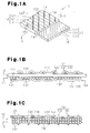
- a fiber fabric 11 is structured by a first fiber layer 12 formed of a plurality of first fiber bundles 121, a second fiber layer 13 formed of a plurality of second fiber bundles 131, a retaining thread group 14 formed of a plurality of retaining threads 141, and a constraint thread group 15 formed of a plurality of constraint threads 151.
- the first fiber layer 12 is laminated in adjacent to the second fiber layer 13.
- the constraint threads 151 extend in a thickness direction of the fiber fabric 11 and pass through the first fiber layer 12 and the second fiber layer 13.
- the retaining threads 141 intersect the constraint threads 151.
- An array pitch of the retaining threads 141 and the constraint threads 151 is set to be wider than an array pitch of the first fiber bundles 121 and the second fiber bundles 131.
- the threads in this case are not limited to the twisted threads, but include fiber bundles in which a lot of fibers are bundled but are not twisted.
- all the first fiber bundles 121 are aligned in one direction. That is, length directions of all the first fiber bundles 121 are aligned in the same direction.
- the length direction of the first fiber bundles 121 is described as a 0 degree direction corresponding to a reference direction. All the retaining threads 141 are aligned in one direction which is different from the length direction of the first fiber bundles 121.
- a direction component of the retaining threads 141 to a direction in which the layers of the first and second fiber layers 12 and 13 are expanded (hereinafter, simply referred to as a layer direction) is a length direction of the retaining threads 141
- the length direction of the retaining threads 141 intersects the length direction of the first fiber bundles 121 at an angle of 45 degrees.
- the length direction of the retaining threads 141 is described as a 45 degree direction.
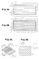
- Fig. 2A expresses the fiber fabric 11 only by the first fiber bundles 121, the retaining threads 141 and the constraint threads 151 for easily understanding
- Fig. 2C is a schematic view expressing the fiber fabric 11 only by the first fiber bundles 121 and the second fiber bundles 131.
- all the second fiber bundles 131 are aligned in one direction which is different from the length direction of the first fiber bundles 121 and the length direction of the retaining threads 141. That is, length directions of all the second fiber bundles 131 are aligned in the same direction.
- the length direction of the second fiber bundles 131 intersects the length direction of the first fiber bundles 121 at an angle of 45 degrees. That is, the length direction of the second fiber bundles 131 is aligned with the length direction of the retaining threads 141.
- the length direction of the second fiber bundles 131 is expressed as a 45 degree direction.
- Fig. 2B expresses the fiber fabric 11 only by the second fiber bundles 131 and the constraint threads 151.
- Each of the first fiber bundles 121, the second fiber bundles 131, the retaining threads 141, and the constraint threads 151 is formed of continuous fibers.
- the numbers of the continuous fibers of the first fiber bundles 121 and the second fiber bundles 131 are respectively about 12000, and the numbers of the continuous fibers of the retaining threads 141 and the constraint threads 151 are respectively about 2000.
- the constraint threads 151 extending in the thickness direction of the fiber fabric 11 and passing through the first fiber layer 12 and the second fiber layer 13 are folded back so as to straddle the retaining threads 141 on a first layer surface 122 (an upper surface in Fig. 1B) of the first fiber layer 12.
- the constraint threads 151 are again inserted to the first fiber layer 12 and the second fiber layer 13 at the next insertion position which is away from a certain one insertion position at the array pitch of the constraint threads 151, on a first layer surface 132 (a lower surface in Fig. 1B) of the second fiber layer 13.
- a portion (hereinafter, referred to as a layer portion 152) of the constraint threads 151 existing on the first layer surface 132 of the second fiber layer 13 is directed to the length direction of the first fiber bundles 121. That is, the portions of the constraint threads 151 in the layer portion 152 are aligned in the length direction (the 0 degree direction) of the first fiber bundles 121.
- the length direction of the constraint thread group 15 is expressed as a 0 degree direction.
- the retaining thread group 14 and the constraint thread group 15 form a woven texture, and the woven texture holds the first fiber layer 12 and the second fiber layer 13 between the retaining thread group 14 and the constraint thread group 15.
- the first fiber layer 12 and the second fiber layer 13 constitute a main body of the fiber fabric 11, the length direction of the first fiber bundles 121 is the 0 degree direction, and the length direction of the second fiber bundles 131 is the 45 degree direction.
- the length directions of the first fiber bundles 121 and the second fiber bundles 131 of the fiber fabric 11 are expressed as a set, and are expressed by (0 degrees, 45 degrees).
- the fiber fabric 11 mentioned above is manufactured, for example, as follows.
- the first fiber layer 12 is formed by folding back and engaging the first fiber bundles 121 with a lot of pins 17 detachably provided in a rising manner in a rectangular frame body 16 at a predetermined pitch.
- the second fiber layer 13 is formed on the first fiber layer 12 by folding back and engaging the second fiber bundles 131 with the pins 17.
- the constraint threads 151 are inserted to the second fiber layer 13 and the first fiber layer 12, for example, in accordance with a method disclosed in Japanese Laid-Open Patent Publication No. 8-218249 . That is, insertion needles are inserted along the thickness directions of the second fiber layer 13 and the first fiber layer 12, in a state in which the constraint threads 151 are each locked to a hole formed in a leading end of the insertion needle. The insertion needles are moved forward to a position in which the holes of the insertion needles pass through the second fiber layer 13 and the first fiber layer 12. Thereafter, the insertion needles are moved backward slightly, and the constraint threads 151 are in a state of forming U-shaped loops.
- retaining threads needles are stopped at a time when the retaining threads needles are passed within the U-shaped loops, and reach the end portions of the second fiber layer 13 and the first fiber layer 12.
- the retaining threads 141 are locked to leading ends of the retaining threads needle.
- the retaining threads needles are pulled back, and the retaining threads 141 are in a state of being inserted into the U-shaped loops of the constraint threads 151. In this state, the insertion needles are pulled back. Accordingly, the retaining threads 141 are fastened by the constraint threads 151, and the fiber fabric 11 is manufactured.
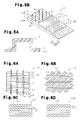
- a mirror fiber fabric 11M shown in Figs. 4A and 4B is structured by a first fiber layer 12M formed of a plurality of first fiber bundles 121, a second fiber layer 13M formed of a plurality of second fiber bundles 131, a retaining thread group 14M formed of a plurality of retaining threads 141, and a constraint thread group 15M formed of a plurality of constraint threads 151.
- Fig. 4B is a schematic view showing the mirror fiber fabric 11M only by the first fiber bundles 121 and the second fiber bundles 131.
- a length direction of the second fiber bundles 131 of the mirror fiber fabric 11M intersects a length direction (the 0 degree direction) of the first fiber bundles 121 of the mirror fiber fabric 11M at an angle of 45 degrees.
- a length direction of the second fiber bundle 131 of the mirror fiber fabric 11M coincides with the length direction of the first fiber layer 12 at a time of rotating only the first fiber layer 12 in the fiber fabric 11 at 90 degrees.
- the length direction of the second fiber bundles 131 of the mirror fiber fabric 11M is expressed as a -45 degree direction.
- the mirror fiber fabric 11M has a mirror symmetrical relation to the fiber fabric 11.
- the mirror symmetrical relation in this case means a mirror symmetrical relation with respect to the length directions of the first fiber bundles 121 and the second fiber bundles 131. That is, the mirror fiber fabric 11M having the mirror symmetrical relation to the fiber fabric 11 is included in the present invention.
- the length direction of the first fiber bundles 121 of the first fiber layer 12M corresponding to a main body of the mirror fiber fabric 11M is the 0 degree direction
- the length direction of the second fiber bundles 131 of the second fiber layer 13M corresponding to a main body of the mirror fiber fabric 11M is the -45 degree direction.
- the length directions of the first and second fiber bundles 121 and 131 of the mirror fiber fabric 11M are expressed by (0 degrees, -45 degrees).
- a carbon fiber and a glass fiber are employed for the first fiber bundles 121 and the second fiber bundles 131.
- polyester and glass fiber are employed for the retaining threads 141 and the constraint threads 151.
- Fig. 5A shows a bumper reinforcement 18 structured by lapping the fiber fabric 11 over the mirror fiber fabric 11M and made of a fiber reinforced resin.
- Fig. 5B shows an overlapped sheet 19 obtained by lapping the fiber fabric 11 over the mirror fiber fabric 11M.
- the mirror fiber fabric 11M in the overlapped sheet 19 is lapped over the fiber fabric 11 by being reversed (reversed right and left) from a state shown in Figs. 4A and 4B.
- the fiber fabric 11 and the mirror fiber fabric 11M constituting the bumper reinforcement 18 are in a mirror symmetrical overlapped state.
- the resin a thermosetting resin such as an epoxy resin, polyester or the like is employed.
- the fiber fabrics 11 and 11M are used such that the first fiber bundles 121 extends in the longitudinal direction of the bumper reinforcement 18.
- the first embodiment has the following advantages.
- the length direction of one of the first fiber bundle 121 and the second fiber bundle 131 is 0 degrees.
- the fiber fabric provided with the first fiber bundles 121 and the second fiber bundles 131 diagonally intersecting with each other at an angle of 45 degrees provide the fiber fabric in which the combinations in the length directions are different, in which the length direction of any one of the first fiber bundles 121 and the second fiber bundles 131 becomes the 0 degree direction or the 90 degree direction, and the direction of the other becomes 45 degrees or -45 degrees, by being reversed, rotated at -45 degrees or rotated at 90 degrees.
- the fiber fabric in which the 45 degree direction and the 0 degree direction are combined [the fiber fabric in which the length directions of the first and second fiber bundles 121 and 131 are (45 degrees, 0 degrees)] is provided by combining the 0 degree direction and the -45 degree direction, that is, reversing the mirror fiber fabric 11M in which the length directions of the first and second fiber bundles 121 and 131 are (0 degrees, -45 degrees).
- the fiber fabric in which the 90 degree direction and the 45 degree direction are combined [the fiber fabric in which the length directions of the first and second fiber bundles 121 and 131 are (90 degrees, 45 degrees)] by rotating the mirror fiber fabric 11M in which the 0 degree direction and the -45 degree direction are combined.
- the fiber fabric in which the -45 degree direction and the 90 degree direction are combined [the fiber fabric in which the length directions of the first and second fiber bundles 121 and 131 are (-45 degrees, 90 degrees)] is provided by rotating the fiber fabric in which the length directions of the first and second fiber bundles 121 and 131 are (45 degrees, 0 degrees) at 90 degrees, or reversing the fiber fabric in which the length directions of the first and second fiber bundles 121 and 131 are (90 degrees, 45 degrees).
- a first overlapped sheet S1 is formed by overlapping the fiber fabric 11 [in which the length directions of the first and second fiber bundles 121 and 131 are (0 degrees, 45 degrees)], and the fiber fabric [in which the length directions of the first and second fiber bundles 121 and 131 are (90 degrees, -45 degrees)] obtained by rotating the fiber fabric 11 at 90 degrees.
- a second overlapped sheet S2 is formed by overlapping the mirror fiber fabric 11M [in which the length directions of the first and second fiber bundles 121 and 131 are (0 degrees, -45 degrees)], and the fiber fabric [in which the length directions of the first and second fiber bundles 121 and 131 are (90 degrees, 45 degrees)] obtained by rotating the mirror fiber fabric 11M at 90 degrees.
- the second overlapped sheet S2 has a mirror symmetrical relation with respect to the first overlapped sheet S1.
- an overlapped sheet in which the length directions of the first and second fiber bundles 121 and 131 are (0 degrees, 45 degrees, 90 degrees, -45 degrees, -45 degrees, 90 degrees, 45 degrees, 0 degrees) can be obtained by overlapping the first overlapped sheet S1 [in which the length directions of the first and second fiber bundles 121 and 131 are (0 degrees, 45 degrees, 90 degrees, -45 degrees)], and the overlapped sheet obtained by reversing the second overlapped sheet [in which the length directions of the first and second fiber bundles 121 and 131 are (-45 degrees, 90 degrees, 45 degrees, 0 degrees)].
- the overlapped sheet obtained by overlapping the first and second overlapped sheets S1 and S2 having the mirror symmetrical relation in a mirror symmetrical manner is preferable for forming the composite material generating no warp.
- the fiber fabrics 11 and 11M obtained by diagonally intersecting the first fiber bundles 121 with the second fiber bundles 131 at 45 degrees make it possible to manufacture the first and second overlapped sheets S1 and S2 having the mirror symmetrical relation.
- the fiber fabric 11 in which the length directions of the first and second fiber bundles 121 and 131 are (0 degrees, 45 degrees), and the mirror fiber fabric 11M in which the length directions of the first and second fiber bundles 121 and 131 are (0 degrees, -45 degrees) are preferable for a raw material of the overlapped sheet for constituting the composite material having a large thickness.
- the present invention may be modified as follows.
- the structure may be made such that the retaining threads 141 intersect the first fiber bundles 121 at an angle of 90 degrees.
- the length directions of the first fiber bundles 121, the second fiber bundles 131 and the constraint threads 151 constituting the fiber fabric 11A are the same as the case of the first embodiment.
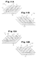
- Fig. 6D shows a mirror fiber fabric 11AM having a mirror symmetrical relation to the fiber fabric 11A.
- the structure may be made such that the length direction of the first fiber bundles 121 is the 45 degree direction, and the length direction of the second fiber bundles 131 is the 90 degree direction.
- the length directions of the retaining threads 141 and the constraint threads 151 constituting the fiber fabric 11B are the same as the case of the first embodiment.
- Fig. 7D shows a mirror fiber fabric 11BM having a mirror symmetrical relation to the fiber fabric 11B.
- the structure may be made such that the length direction of the first fiber bundles 121 is the 90 degree direction, and the length direction of the second fiber bundles 131 is the 45 degree direction.
- the length directions of the retaining threads 141 and the constraint threads 151 constituting the fiber fabric 11C are the same as the case of the first embodiment.
- Fig. 8D shows a mirror fiber fabric 11CM having a mirror symmetrical relation to the fiber fabric 11C.
- the structure may be made such that the length direction of the constraint threads 151 is the -45 degree direction.
- the length directions of the first fiber bundles 121, the second fiber bundles 131 and the retaining threads 141 constituting the fiber fabric 11D are the same as the case of the first embodiment.
- Fig. 9B shows a mirror fiber fabric 11DM having a mirror symmetrical relation to the fiber fabric 11D.
- the structure may be made such that the length direction of the constraint threads 151 is the -45 degree direction.
- the length directions of the first fiber bundles 121, the second fiber bundles 131 and the retaining threads 141 constituting the fiber fabric 11E are the same as the case of the second embodiment.
- Fig. 10B shows a mirror fiber fabric 11EM having a mirror symmetrical relation to the fiber fabric 11E.
- the structure may be made such that the length direction of the constraint threads 151 is the -45 degree direction.
- the length directions of the first fiber bundles 121, the second fiber bundles 131 and the retaining threads 141 constituting the fiber fabric 11F are the same as the case of the third embodiment.
- Fig. 11B shows a mirror fiber fabric 11FM having a mirror symmetrical relation to the fiber fabric 11D.
- the structure may be made such that the length direction of the constraint threads 151 is the -45 degree direction.
- the length directions of the first fiber bundles 121, the second fiber bundles 131 and the retaining threads 141 constituting the fiber fabric 11G are the same as the case of the fourth embodiment.
- Fig. 12B shows a mirror fiber fabric 11GM having a mirror symmetrical relation to the fiber fabric 11G.
- the structure may be made such that the length direction of the constraint threads 151 is the 90 degree direction.
- the length directions of the first fiber bundles 121, the second fiber bundles 131 and the retaining threads 141 constituting the fiber fabric 11H are the same as the case of the first embodiment.
- Fig. 13B shows a mirror fiber fabric 11HM having a mirror symmetrical relation to the fiber fabric 11H.
- the structure may be made such that the length direction of the constraint threads 151 is the 90 degree direction.
- the length direction of the first fiber bundles 121 constituting the fiber fabric 11J is the 45 degree direction
- the length direction of the second fiber bundles 131 is the 0 degree direction
- the length direction of the retaining threads 141 is the 0 degree direction.
- Fig. 14B shows a mirror fiber fabric 11HM having a mirror symmetrical relation to the fiber fabric 11J.
- the structure may be made such that the length direction of one of the first fiber bundles 121 and the second fiber bundles 131 constituting the fiber fabric 11K is set to a 22.5 degree direction, and the other is set to a - 22.5 degree direction.
- a case is considered below in which a beam is formed in such a manner that the first fiber bundles 121 diagonally intersect the second fiber bundles 131 at an angle of 22.5 degrees with respect to a longitudinal direction of the beam.
- the beam having a necessary dimension is cut by cutting the fiber fabric 11 in a direction of 22.5 degrees with respect to the 0 degree direction of the first fiber bundles 121, and cutting in a direction of -67.5 degrees.
- a lot of portions of the fiber fabric 11 will be of no use.
- the structure may be made such that the length direction of one of the first fiber bundles 121 and the second fiber bundles 131 constituting the fiber fabric 11L is set to a 67.5 degree direction, and the other is set to a - 67.5 degree direction.
- a case is considered below in which a beam is formed in such a manner that the first fiber bundles 121 diagonally intersect the second fiber bundles 131 at an angle of 67.5 degrees with respect to a longitudinal direction of the beam.
- the beam having a necessary dimension is cut by cutting the fiber fabric 11 in a direction of 67.5 degrees with respect to the 0 degree direction of the first fiber bundles 121, and cutting in a direction of -22.5 degrees.
- a lot of portions of the fiber fabric 11 will be of no use.
- the fiber kinds of the first fiber bundles 121 and the second fiber bundles 131 may be differentiated.
- a fiber fabric (11) includes a first fiber layer (12) formed of a plurality of first fiber bundles (121), a second fiber layer (13) formed of a plurality of second fiber bundles (131), a retaining thread group (14) formed of a plurality of retaining threads (141), and a constraint thread group (15) formed of a plurality of constraint threads (151).
- the first fiber layer (12) is laminated in adjacent to the second fiber layer (13).
- the first fiber bundles (121) diagonally intersect the second fiber bundles (131) at an angle of 45 degrees. Accordingly, it is possible to improve a production efficiency of an overlapped sheet which gives excellent moldability and a strength, and has an increased thickness by overlapping the fiber fabrics (Fig. 1A).
Landscapes
- Engineering & Computer Science (AREA)
- Textile Engineering (AREA)
- General Engineering & Computer Science (AREA)
- Mechanical Engineering (AREA)
- Woven Fabrics (AREA)
- Reinforced Plastic Materials (AREA)
- Laminated Bodies (AREA)
- Manufacturing Of Multi-Layer Textile Fabrics (AREA)
Abstract
Description
- The present invention relates to a fiber fabric and a composite material obtained by reinforcing a resin by the fiber fabric.
- A load energy absorbing member constructing a bumper apparatus cushioning an impact at a collision of a vehicle absorbs the energy of an impact load applied to a bumper reinforcement constructing the bumper apparatus. In order to save weight of the bumper apparatus, there has been known a composite material in which the bumper reinforcement or the load energy absorbing member is formed by a fiber reinforced resin.
- As the fiber for reinforcing the resin, for example, fabrics disclosed in the following publication can be employed.
- A fabric disclosed in
Japanese Laid-Open Patent Publication No. 63-303145 - In a fabric disclosed in
Japanese Laid-Open Patent Publication No. 7-243147 - In a fabric disclosed in
Japanese Laid-Open Patent Publication No. 7-243149 - In order to increase the thickness of a composite material, it is preferable to overlap a plurality of fabrics. However, since the fabric in the
Japanese Laid-Open Patent Publication No. 7-243149 - Accordingly, it is an objective of the present invention to provide a fiber fabric which has excellent moldability and strength, and improves the production efficiency of an overlapped sheet the thickness of which is increased by overlapping the fiber fabrics, and to a composite material made of a fiber reinforced resin using the fiber fabric.
- In order to achieve the object mentioned above, the present invention provides a fiber fabric. The fiber fabric has a first fiber layer formed of a plurality of first fiber bundles having mutually aligned length directions, and a second fiber layer formed of a plurality of second fiber bundles having mutually aligned length directions. The length direction of the second fiber bundle obliquely interests the first fiber bundle. The fiber fabric further has a retaining thread group formed of a plurality of retaining threads having mutually aligned length directions, and a constraint thread group formed of a plurality of constraint threads having mutually aligned length directions. The length direction of the constraint thread intersects the retaining thread. The first fiber layer is laminated in adjacent to the second fiber layer. The retaining thread group and the constraint thread group form a fabric texture, and hold the first fiber layer and the second fiber layer.
- Further, the present invention provides a composite material provided with the fiber fabric and a resin reinforced by the fiber fabric.
- Other aspects and advantages of the invention will become apparent from the following description, taken in conjunction with the accompanying drawings, illustrating by way of example the principles of the invention.
- The features of the present invention that are believed to be novel are set forth with particularity in the appended claims. The invention, together with objects and advantages thereof, may best be understood by reference to the following description of the presently preferred embodiments together with the accompanying drawings in which:
- Fig. 1A is a partially cut away schematic perspective view of a fiber fabric in accordance with a first embodiment according to the present invention;
- Fig. 1B is a cross-sectional view taken along a line IB-IB in Fig. 1A;
- Fig. 1C is a cross-sectional view taken along a line IC-IC in Fig. 1A;
- Fig. 2A is a view showing one surface of the fiber fabric in Fig. 1A;
- Fig. 2B is a view showing the other surface of the fiber fabric in Fig. 1A;
- Fig. 2C is a schematic view showing one surface of the fiber fabric in Fig. 1A;
- Figs. 3A and 3B are plan views explaining manufacturing steps of the fiber fabric in Fig. 1A;
- Fig. 4A is a partially cut away schematic perspective view of a fiber fabric which is mirror symmetrical to the fiber fabric in Fig. 1A;
- Fig. 4B is a schematic view showing one surface of the fiber fabric in Fig. 4A;
- Fig. 5A is a cross-sectional view of a bumper reinforcement formed of the fiber fabric in Fig. 1A and the fiber fabric in Fig. 4A;
- Fig. 5B is a partially cut away schematic perspective view of an overlapped sheet formed of the fiber fabric in Fig. 1A and the fiber fabric in Fig. 4A;
- Fig. 6A is a view showing one surface of a fiber fabric in accordance with a second embodiment of the present invention;
- Fig. 6B is a view showing the other surface of the fiber fabric in Fig. 6A;
- Fig. 6C is a schematic view showing one surface of the fiber fabric in Fig. 6A;
- Fig. 6D is a schematic view showing one surface of a fiber fabric which is mirror symmetrical to the fiber fabric in Fig. 6C;
- Fig. 7A is a view showing one surface of a fiber fabric in accordance with a third embodiment of the present invention;
- Fig. 7B is a view showing the other surface of the fiber fabric in Fig. 7A;
- Fig. 7C is a schematic view showing one surface of the fiber fabric in Fig. 7A;
- Fig. 7D is a schematic view showing one surface of a fiber fabric which is mirror symmetrical to the fiber fabric in Fig. 7C;
- Fig. 8A is a view showing one surface of a fiber fabric in accordance with a fourth embodiment of the present invention;
- Fig. 8B is a view showing the other surface of the fiber fabric in Fig. 8A;
- Fig. 8C is a schematic view showing one surface of the fiber fabric in Fig. 8A;
- Fig. 8D is a schematic view showing one surface of a fiber fabric which is mirror symmetrical to the fiber fabric in Fig. 8C;
- Fig. 9A is a brief perspective view of a fiber fabric in accordance with another embodiment of the present invention;
- Fig. 9B is a brief perspective view of a fiber fabric which is mirror symmetrical to the fiber fabric in Fig. 9A;
- Fig. 10A is a brief perspective view of a fiber fabric in accordance with a further embodiment of the present invention;
- Fig. 10B is a brief perspective view of a fiber fabric which is mirror symmetrical to the fiber fabric in Fig. 10A;
- Fig. 11A is a brief perspective view of a fiber fabric in accordance with a further embodiment of the present invention;
- Fig. 11B is a brief perspective view of a fiber fabric which is mirror symmetrical to the fiber fabric in Fig. 11A;
- Fig. 12A is a brief perspective view of a fiber fabric in accordance with a further embodiment of the present invention;
- Fig. 12B is a brief perspective view of a fiber fabric which is mirror symmetrical to the fiber fabric in Fig. 12A;
- Fig. 13A is a brief perspective view of a fiber fabric in accordance with a further embodiment of the present invention;
- Fig. 13B is a brief perspective view of a fiber fabric which is mirror symmetrical to the fiber fabric in Fig. 13A;
- Fig. 14A is a brief perspective view of a fiber fabric in accordance with a further embodiment of the present invention;
- Fig. 14B is a brief perspective view of a fiber fabric which is mirror symmetrical to the fiber fabric in Fig. 14A;
- Fig. 15 is a schematic view showing a fiber fabric in accordance a further embodiment of the present invention; and
- Fig. 16 is a schematic view showing a fiber fabric in accordance a further other embodiment of the present invention.
- A description will be given of a first embodiment according to the present invention on the basis of Figs. 1A to 5B.
- As shown in Figs. 1A to 1C, a
fiber fabric 11 is structured by afirst fiber layer 12 formed of a plurality offirst fiber bundles 121, asecond fiber layer 13 formed of a plurality ofsecond fiber bundles 131, a retainingthread group 14 formed of a plurality of retainingthreads 141, and aconstraint thread group 15 formed of a plurality ofconstraint threads 151. Thefirst fiber layer 12 is laminated in adjacent to thesecond fiber layer 13. Theconstraint threads 151 extend in a thickness direction of thefiber fabric 11 and pass through thefirst fiber layer 12 and thesecond fiber layer 13. The retainingthreads 141 intersect theconstraint threads 151. An array pitch of the retainingthreads 141 and theconstraint threads 151 is set to be wider than an array pitch of thefirst fiber bundles 121 and the second fiber bundles 131. The threads in this case are not limited to the twisted threads, but include fiber bundles in which a lot of fibers are bundled but are not twisted. - As shown in Figs. 2A and 2C, all the
first fiber bundles 121 are aligned in one direction. That is, length directions of all thefirst fiber bundles 121 are aligned in the same direction. Hereinafter, the length direction of thefirst fiber bundles 121 is described as a 0 degree direction corresponding to a reference direction. All the retainingthreads 141 are aligned in one direction which is different from the length direction of the first fiber bundles 121. That is, on the assumption that a direction component of the retainingthreads 141 to a direction in which the layers of the first and second fiber layers 12 and 13 are expanded (hereinafter, simply referred to as a layer direction) is a length direction of the retainingthreads 141, the length direction of the retainingthreads 141 intersects the length direction of thefirst fiber bundles 121 at an angle of 45 degrees. Hereinafter, the length direction of the retainingthreads 141 is described as a 45 degree direction. In this case, Fig. 2A expresses thefiber fabric 11 only by thefirst fiber bundles 121, the retainingthreads 141 and theconstraint threads 151 for easily understanding, and Fig. 2C is a schematic view expressing thefiber fabric 11 only by thefirst fiber bundles 121 and the second fiber bundles 131. - As shown in Figs. 2B to 2C, all the
second fiber bundles 131 are aligned in one direction which is different from the length direction of thefirst fiber bundles 121 and the length direction of the retainingthreads 141. That is, length directions of all thesecond fiber bundles 131 are aligned in the same direction. The length direction of thesecond fiber bundles 131 intersects the length direction of thefirst fiber bundles 121 at an angle of 45 degrees. That is, the length direction of thesecond fiber bundles 131 is aligned with the length direction of the retainingthreads 141. Hereinafter, the length direction of thesecond fiber bundles 131 is expressed as a 45 degree direction. On the assumption that a direction component of theconstraint threads 151 in the layer direction of the first and second fiber layers 12 and 13 is the length direction of theconstraint threads 151, the length direction of all theconstraint threads 151 are aligned with the length direction of the first fiber bundles 121. In this case, Fig. 2B expresses thefiber fabric 11 only by thesecond fiber bundles 131 and theconstraint threads 151. - Each of the
first fiber bundles 121, thesecond fiber bundles 131, the retainingthreads 141, and theconstraint threads 151 is formed of continuous fibers. In the present embodiment, the numbers of the continuous fibers of thefirst fiber bundles 121 and thesecond fiber bundles 131 are respectively about 12000, and the numbers of the continuous fibers of the retainingthreads 141 and theconstraint threads 151 are respectively about 2000. - As shown in Fig. 1B, the
constraint threads 151 extending in the thickness direction of thefiber fabric 11 and passing through thefirst fiber layer 12 and thesecond fiber layer 13 are folded back so as to straddle the retainingthreads 141 on a first layer surface 122 (an upper surface in Fig. 1B) of thefirst fiber layer 12. Theconstraint threads 151 are again inserted to thefirst fiber layer 12 and thesecond fiber layer 13 at the next insertion position which is away from a certain one insertion position at the array pitch of theconstraint threads 151, on a first layer surface 132 (a lower surface in Fig. 1B) of thesecond fiber layer 13. A portion (hereinafter, referred to as a layer portion 152) of theconstraint threads 151 existing on thefirst layer surface 132 of thesecond fiber layer 13 is directed to the length direction of the first fiber bundles 121. That is, the portions of theconstraint threads 151 in thelayer portion 152 are aligned in the length direction (the 0 degree direction) of the first fiber bundles 121. Hereinafter, the length direction of theconstraint thread group 15 is expressed as a 0 degree direction. - The retaining
thread group 14 and theconstraint thread group 15 form a woven texture, and the woven texture holds thefirst fiber layer 12 and thesecond fiber layer 13 between the retainingthread group 14 and theconstraint thread group 15. Thefirst fiber layer 12 and thesecond fiber layer 13 constitute a main body of thefiber fabric 11, the length direction of thefirst fiber bundles 121 is the 0 degree direction, and the length direction of thesecond fiber bundles 131 is the 45 degree direction. Hereinafter, the length directions of thefirst fiber bundles 121 and thesecond fiber bundles 131 of thefiber fabric 11 are expressed as a set, and are expressed by (0 degrees, 45 degrees). - The
fiber fabric 11 mentioned above is manufactured, for example, as follows. - As shown in Fig. 3A, the
first fiber layer 12 is formed by folding back and engaging thefirst fiber bundles 121 with a lot ofpins 17 detachably provided in a rising manner in arectangular frame body 16 at a predetermined pitch. Next, as shown in Fig. 3B, thesecond fiber layer 13 is formed on thefirst fiber layer 12 by folding back and engaging thesecond fiber bundles 131 with thepins 17. - Next, the
constraint threads 151 are inserted to thesecond fiber layer 13 and thefirst fiber layer 12, for example, in accordance with a method disclosed inJapanese Laid-Open Patent Publication No. 8-218249 second fiber layer 13 and thefirst fiber layer 12, in a state in which theconstraint threads 151 are each locked to a hole formed in a leading end of the insertion needle. The insertion needles are moved forward to a position in which the holes of the insertion needles pass through thesecond fiber layer 13 and thefirst fiber layer 12. Thereafter, the insertion needles are moved backward slightly, and theconstraint threads 151 are in a state of forming U-shaped loops. Next, retaining threads needles are stopped at a time when the retaining threads needles are passed within the U-shaped loops, and reach the end portions of thesecond fiber layer 13 and thefirst fiber layer 12. At this time, the retainingthreads 141 are locked to leading ends of the retaining threads needle. Further, the retaining threads needles are pulled back, and the retainingthreads 141 are in a state of being inserted into the U-shaped loops of theconstraint threads 151. In this state, the insertion needles are pulled back. Accordingly, the retainingthreads 141 are fastened by theconstraint threads 151, and thefiber fabric 11 is manufactured. - A
mirror fiber fabric 11M shown in Figs. 4A and 4B is structured by afirst fiber layer 12M formed of a plurality offirst fiber bundles 121, asecond fiber layer 13M formed of a plurality ofsecond fiber bundles 131, a retainingthread group 14M formed of a plurality of retainingthreads 141, and aconstraint thread group 15M formed of a plurality ofconstraint threads 151. Fig. 4B is a schematic view showing themirror fiber fabric 11M only by thefirst fiber bundles 121 and the second fiber bundles 131. A length direction of thesecond fiber bundles 131 of themirror fiber fabric 11M intersects a length direction (the 0 degree direction) of thefirst fiber bundles 121 of themirror fiber fabric 11M at an angle of 45 degrees. A length direction of thesecond fiber bundle 131 of themirror fiber fabric 11M coincides with the length direction of thefirst fiber layer 12 at a time of rotating only thefirst fiber layer 12 in thefiber fabric 11 at 90 degrees. Hereinafter, the length direction of thesecond fiber bundles 131 of themirror fiber fabric 11M is expressed as a -45 degree direction. Themirror fiber fabric 11M has a mirror symmetrical relation to thefiber fabric 11. The mirror symmetrical relation in this case means a mirror symmetrical relation with respect to the length directions of thefirst fiber bundles 121 and the second fiber bundles 131. That is, themirror fiber fabric 11M having the mirror symmetrical relation to thefiber fabric 11 is included in the present invention. - The length direction of the
first fiber bundles 121 of thefirst fiber layer 12M corresponding to a main body of themirror fiber fabric 11M is the 0 degree direction, and the length direction of thesecond fiber bundles 131 of thesecond fiber layer 13M corresponding to a main body of themirror fiber fabric 11M is the -45 degree direction. Hereinafter, the length directions of the first andsecond fiber bundles mirror fiber fabric 11M are expressed by (0 degrees, -45 degrees). - In this case, for example, a carbon fiber and a glass fiber are employed for the
first fiber bundles 121 and the second fiber bundles 131. For example, polyester and glass fiber are employed for the retainingthreads 141 and theconstraint threads 151. - Fig. 5A shows a
bumper reinforcement 18 structured by lapping thefiber fabric 11 over themirror fiber fabric 11M and made of a fiber reinforced resin. Fig. 5B shows an overlappedsheet 19 obtained by lapping thefiber fabric 11 over themirror fiber fabric 11M. Themirror fiber fabric 11M in the overlappedsheet 19 is lapped over thefiber fabric 11 by being reversed (reversed right and left) from a state shown in Figs. 4A and 4B. Thefiber fabric 11 and themirror fiber fabric 11M constituting thebumper reinforcement 18 are in a mirror symmetrical overlapped state. As the resin, a thermosetting resin such as an epoxy resin, polyester or the like is employed. - In the
bumper reinforcement 18 corresponding to the composite material, thefiber fabrics first fiber bundles 121 extends in the longitudinal direction of thebumper reinforcement 18. - The first embodiment has the following advantages.
- (1) Since the first fiber layers 12 and 12M and the second fiber layers 13 and 13M have no crimp, the
fiber fabrics bumper reinforcement 18 in the present embodiment) made of the fiber reinforced resin, and give excellent moldability. Further, since thefiber fabrics sheet 19 in which the thickness is increased by overlapping thefiber fabrics - (2) The retaining
threads 141 brought into contact with thelayer surface 122 of thefirst fiber layer 12 are aligned in the length direction of thesecond fiber bundles 131 of thesecond fiber layer 13. Since thefirst fiber bundles 121 of thefirst fiber layer 12 diagonally intersect thesecond fiber bundles 131 of thesecond fiber layer 13, the retainingthreads 141 cannot fail to intersect thefirst fiber bundles 121 of thefirst fiber layer 12 brought into contact with the retainingthreads 141 in thelayer surface 122. In the same manner, the retainingthreads 141 brought into contact with thelayer surface 122 of thefirst fiber layer 12M are aligned in the length direction of thesecond fiber bundles 131 of thesecond fiber layer 13M. That is, the retainingthreads 141 of the retainingthread group 14M cannot fail to intersect thefirst fiber bundles 121 of thefirst fiber layer 12M brought into contact with the retainingthreads 141 in thelayer surface 122.
On the other hand, theconstraint threads 151 in thelayer portion 152 of theconstraint thread group 15 brought into contact with thefirst layer surface 132 of thesecond fiber layer 13 are aligned in the direction of thefirst fiber bundles 121 of thefirst fiber layer 12. Thefirst fiber bundles 121 of thefirst fiber layer 12 diagonally intersect thesecond fiber bundles 131 of thesecond fiber layer 13. Accordingly, theconstraint threads 151 in thelayer portion 152 cannot fail to intersect thesecond fiber bundles 131 of thesecond fiber layer 13 brought into contact with thelayer portions 152 in the first layer surfaces 132. In the same manner, theconstraint threads 151 of theconstraint thread group 15M cannot fail to intersect thesecond fiber bundles 131 of thesecond fiber layer 13M brought into contact with theconstraint threads 151 in thefirst layer surface 132.
Accordingly, thefirst fiber layer 12 and thesecond fiber layer 13 sandwiched between the retainingthread group 14 and thelayer portion 152 of theconstraint thread group 15 are well held by a constraining effect on the basis of a cooperation of the retainingthreads 141 and theconstraint threads 151, in such a manner as to prevent the array of the fiber bundles from being disturbed.
In the structure in which the length direction of the retainingthreads 141 is aligned with the length direction of thesecond fiber bundles 131, and the length direction of theconstraint threads 151 is aligned with the length direction of thefirst fiber bundles 121, the number of the fiber directions in the fiber fabric is only two. Accordingly, the structure in which the length direction of the retainingthreads 141 brought into contact with thefirst fiber layer 12 is aligned with the length direction of thesecond fiber bundles 131, and the length direction of theconstraint threads 151 brought into contact with thesecond fiber layer 13 via thelayer portion 152 is aligned with the length direction of thefirst fiber bundles 121 is optimum for obtaining an excellent moldability. - (3) It is possible to increase the strength of the
bumper reinforcement 18 by enlarging a wall thickness of thebumper reinforcement 18. In order to enlarge the wall thickness, it is preferable to overlap a plurality offiber fabrics 11, overlap a plurality ofmirror fiber fabrics 11M or lap thefiber fabric 11 over themirror fiber fabric 11M. In particular, the overlappedsheet 19 obtained by overlapping the fiber fabric 11 [the fiber fabric in which the length directions of the first andsecond fiber bundles mirror fiber fabric 11M [the fiber fabric in which the length directions of the first andsecond fiber bundles second fiber bundles mirror fiber fabric 11M becomes (45 degrees, 0 degrees). The length direction of the first andsecond fiber bundles sheet 19 obtained by overlapping the fiber fabric in which the length directions of the first andsecond fiber bundles fiber fabric 11 in which the length directions of the first andsecond fiber bundles - (4) The fiber fabric obtained by combining the -45 degree direction and the 0 degree direction [the fiber fabric in which the length directions of the first and
second fiber bundles fiber fabric 11 in which the length directions of the first andsecond fiber bundles second fiber bundles fiber fabric 11 obtained by combining the 0 direction and the 45 direction. The fiber fabric obtained by combining the 45 degree direction and the 90 degree direction [the fiber fabric in which the length directions of the first andsecond fiber bundles second fiber bundles second fiber bundles - For example, it is assumed that the length direction of one of the
first fiber bundle 121 and thesecond fiber bundle 131 is 0 degrees. In this case, the fiber fabric provided with thefirst fiber bundles 121 and thesecond fiber bundles 131 diagonally intersecting with each other at an angle of 45 degrees provide the fiber fabric in which the combinations in the length directions are different, in which the length direction of any one of thefirst fiber bundles 121 and thesecond fiber bundles 131 becomes the 0 degree direction or the 90 degree direction, and the direction of the other becomes 45 degrees or -45 degrees, by being reversed, rotated at -45 degrees or rotated at 90 degrees. - In the same manner, the fiber fabric in which the 45 degree direction and the 0 degree direction are combined [the fiber fabric in which the length directions of the first and
second fiber bundles mirror fiber fabric 11M in which the length directions of the first andsecond fiber bundles second fiber bundles mirror fiber fabric 11M in which the 0 degree direction and the -45 degree direction are combined. The fiber fabric in which the -45 degree direction and the 90 degree direction are combined [the fiber fabric in which the length directions of the first andsecond fiber bundles second fiber bundles second fiber bundles - For example, in order to form the overlapped sheet in which the length directions of the first and
second fiber bundles second fiber bundles second fiber bundles fiber fabric 11 at 90 degrees. Further, a second overlapped sheet S2 is formed by overlapping themirror fiber fabric 11M [in which the length directions of the first andsecond fiber bundles second fiber bundles mirror fiber fabric 11M at 90 degrees. The second overlapped sheet S2 has a mirror symmetrical relation with respect to the first overlapped sheet S1. Further, an overlapped sheet in which the length directions of the first andsecond fiber bundles second fiber bundles second fiber bundles - The overlapped sheet obtained by overlapping the first and second overlapped sheets S1 and S2 having the mirror symmetrical relation in a mirror symmetrical manner is preferable for forming the composite material generating no warp. The
fiber fabrics first fiber bundles 121 with thesecond fiber bundles 131 at 45 degrees make it possible to manufacture the first and second overlapped sheets S1 and S2 having the mirror symmetrical relation. That is, thefiber fabric 11 in which the length directions of the first andsecond fiber bundles mirror fiber fabric 11M in which the length directions of the first andsecond fiber bundles - The present invention may be modified as follows.
- As shown in Figs. 6A to 6C, the structure may be made such that the retaining
threads 141 intersect thefirst fiber bundles 121 at an angle of 90 degrees. The length directions of thefirst fiber bundles 121, thesecond fiber bundles 131 and theconstraint threads 151 constituting the fiber fabric 11A are the same as the case of the first embodiment. Fig. 6D shows a mirror fiber fabric 11AM having a mirror symmetrical relation to the fiber fabric 11A. - As shown in Figs. 7A to 7C, the structure may be made such that the length direction of the
first fiber bundles 121 is the 45 degree direction, and the length direction of thesecond fiber bundles 131 is the 90 degree direction. The length directions of the retainingthreads 141 and theconstraint threads 151 constituting thefiber fabric 11B are the same as the case of the first embodiment. Fig. 7D shows a mirror fiber fabric 11BM having a mirror symmetrical relation to thefiber fabric 11B. - As shown in Figs. 8A to 8C, the structure may be made such that the length direction of the
first fiber bundles 121 is the 90 degree direction, and the length direction of thesecond fiber bundles 131 is the 45 degree direction. The length directions of the retainingthreads 141 and theconstraint threads 151 constituting thefiber fabric 11C are the same as the case of the first embodiment. Fig. 8D shows a mirror fiber fabric 11CM having a mirror symmetrical relation to thefiber fabric 11C. - As shown in Fig. 9A, the structure may be made such that the length direction of the
constraint threads 151 is the -45 degree direction. The length directions of thefirst fiber bundles 121, thesecond fiber bundles 131 and the retainingthreads 141 constituting thefiber fabric 11D are the same as the case of the first embodiment. Fig. 9B shows a mirror fiber fabric 11DM having a mirror symmetrical relation to thefiber fabric 11D. - As shown in Fig. 10A, the structure may be made such that the length direction of the
constraint threads 151 is the -45 degree direction. The length directions of thefirst fiber bundles 121, thesecond fiber bundles 131 and the retainingthreads 141 constituting thefiber fabric 11E are the same as the case of the second embodiment. Fig. 10B shows a mirror fiber fabric 11EM having a mirror symmetrical relation to thefiber fabric 11E. - As shown in Fig. 11A, the structure may be made such that the length direction of the
constraint threads 151 is the -45 degree direction. The length directions of thefirst fiber bundles 121, thesecond fiber bundles 131 and the retainingthreads 141 constituting thefiber fabric 11F are the same as the case of the third embodiment. Fig. 11B shows a mirror fiber fabric 11FM having a mirror symmetrical relation to thefiber fabric 11D. - As shown in Fig. 12A, the structure may be made such that the length direction of the
constraint threads 151 is the -45 degree direction. The length directions of thefirst fiber bundles 121, thesecond fiber bundles 131 and the retainingthreads 141 constituting thefiber fabric 11G are the same as the case of the fourth embodiment. Fig. 12B shows a mirror fiber fabric 11GM having a mirror symmetrical relation to thefiber fabric 11G. - As shown in Fig. 13A, the structure may be made such that the length direction of the
constraint threads 151 is the 90 degree direction. The length directions of thefirst fiber bundles 121, thesecond fiber bundles 131 and the retainingthreads 141 constituting thefiber fabric 11H are the same as the case of the first embodiment. Fig. 13B shows a mirror fiber fabric 11HM having a mirror symmetrical relation to thefiber fabric 11H. - As shown in Fig. 14A, the structure may be made such that the length direction of the
constraint threads 151 is the 90 degree direction. The length direction of thefirst fiber bundles 121 constituting thefiber fabric 11J is the 45 degree direction, the length direction of thesecond fiber bundles 131 is the 0 degree direction, and the length direction of the retainingthreads 141 is the 0 degree direction. Fig. 14B shows a mirror fiber fabric 11HM having a mirror symmetrical relation to thefiber fabric 11J. - As shown in Fig. 15, the structure may be made such that the length direction of one of the
first fiber bundles 121 and thesecond fiber bundles 131 constituting thefiber fabric 11K is set to a 22.5 degree direction, and the other is set to a - 22.5 degree direction. - For example, a case is considered below in which a beam is formed in such a manner that the
first fiber bundles 121 diagonally intersect thesecond fiber bundles 131 at an angle of 22.5 degrees with respect to a longitudinal direction of the beam. In the case of using thefiber fabric 11 manufactured in a rectangular shape in the first embodiment, the beam having a necessary dimension is cut by cutting thefiber fabric 11 in a direction of 22.5 degrees with respect to the 0 degree direction of thefirst fiber bundles 121, and cutting in a direction of -67.5 degrees. However, in the case of cutting the beam having the necessary dimension from thefiber fabric 11 by cutting in the manner mentioned above, a lot of portions of thefiber fabric 11 will be of no use. - In the case of cutting a beam having the necessary dimension from the
fiber fabric 11K manufactured in the rectangular shape as shown in Fig. 15, it is preferable to cut thefiber fabric 11K in the 0 direction and the 90 degree direction, and little useless portion is generated. - As shown in Fig. 16, the structure may be made such that the length direction of one of the
first fiber bundles 121 and thesecond fiber bundles 131 constituting thefiber fabric 11L is set to a 67.5 degree direction, and the other is set to a - 67.5 degree direction. - For example, a case is considered below in which a beam is formed in such a manner that the
first fiber bundles 121 diagonally intersect thesecond fiber bundles 131 at an angle of 67.5 degrees with respect to a longitudinal direction of the beam. In the case of using thefiber fabric 11 manufactured in a rectangular shape in the first embodiment, the beam having a necessary dimension is cut by cutting thefiber fabric 11 in a direction of 67.5 degrees with respect to the 0 degree direction of thefirst fiber bundles 121, and cutting in a direction of -22.5 degrees. However, in the case of cutting the beam having the necessary dimension from thefiber fabric 11 by cutting in the manner mentioned above, a lot of portions of thefiber fabric 11 will be of no use. - In the case of cutting the necessary dimension from the
fiber fabric 11L manufactured in the rectangular shape as shown in Fig. 16, it is preferable to cut thefiber fabric 11L in the 0 direction and the 90 degree direction, and little useless portion is generated. - The fiber kinds of the
first fiber bundles 121 and thesecond fiber bundles 131 may be differentiated. For example, it is possible to employ a combination such that thefirst fiber bundles 121 are formed of the carbon fiber and thesecond fiber bundles 131 are formed of the glass fiber, or that thefirst fiber bundles 121 are formed of the aramid fiber and thesecond fiber bundles 131 are formed of the carbon fiber, or the like. - A fiber fabric (11) includes a first fiber layer (12) formed of a plurality of first fiber bundles (121), a second fiber layer (13) formed of a plurality of second fiber bundles (131), a retaining thread group (14) formed of a plurality of retaining threads (141), and a constraint thread group (15) formed of a plurality of constraint threads (151). The first fiber layer (12) is laminated in adjacent to the second fiber layer (13). The first fiber bundles (121) diagonally intersect the second fiber bundles (131) at an angle of 45 degrees. Accordingly, it is possible to improve a production efficiency of an overlapped sheet which gives excellent moldability and a strength, and has an increased thickness by overlapping the fiber fabrics (Fig. 1A).
Claims (7)
- A fiber fabric (11) characterized by:a first fiber layer (12) formed of a plurality of first fiber bundles (121) having a mutually aligned length direction;a second fiber layer (13) formed of a plurality of second fiber bundles (131) having a mutually aligned length direction, the length direction of the second fiber bundles (131) diagonally intersecting the first fiber bundles (121);a retaining thread group (14) formed of a plurality of retaining threads (141) having a mutually aligned length direction; anda constraint thread group (15) formed of a plurality of constraint threads (151) having a mutually aligned length direction, the length direction of the constraint threads (151) intersecting the retaining threads (141),wherein the first fiber layer (12) is laminated in adjacent to the second fiber layer (13), and the retaining thread group (14) and the constraint thread group (15) form a woven texture so as to hold the first fiber layer (12) and the second fiber layer (13).
- The fiber fabric (11) according to claim 1, characterized in that the retaining threads (141) are brought into contact with a layer surface (122) of one (12) of the first fiber layer (12) and the second fiber layer (13), and the length direction of the retaining threads (141) is aligned with the length direction of the fiber bundles (131) of the other one (13) of the first fiber layer (12) and the second fiber layer (13).
- The fiber fabric (11) according to claim 1, characterized in that the constraint threads (151) have a portion (152) brought into contact with a layer surface (132) of one (13) of the first fiber layer (12) and the second fiber layer (13), and a length direction of the portion (152) is aligned with the length direction of the fiber bundles (121) of the other one (12) of the first fiber layer (12) and the second fiber layer (13).
- The fiber fabric (11) according to claim 1, characterized in that the retaining threads (141) are brought into contact with a layer surface (122) of one (12) of the first fiber layer (12) and the second fiber layer (13), the length direction of the retaining threads (141) is aligned with the length direction of the fiber bundles (131) of the other one (13) of the first fiber layer (12) and the second fiber layer (13), and the constraint threads (151) has a portion (152) brought into contact with a layer surface (132) of said other one (13) of the first fiber layer (12) and the second fiber layer (13), and a length direction of the portion (152) is aligned with the length direction of the fiber bundles (121) of said one (12) of the first fiber layer (12) and the second fiber layer (13).
- The fiber fabric (11) according to any one of claims 1 to 4, characterized in that the length direction of the first fiber bundles (121) diagonally intersects the length direction of the second fiber bundles (131) at an angle of 45 degrees.
- A composite material (18) characterized by:the fiber fabric (11) according to any one of claims 1 to 5; anda resin reinforced by the fiber fabric (11).
- The composite material (18) according to claim 6, characterized in that the composite material is provided with the fiber fabric (11), and a mirror fiber fabric (11M) arranged in mirror symmetrical to the fiber fabric (11).
Applications Claiming Priority (1)
| Application Number | Priority Date | Filing Date | Title |
|---|---|---|---|
| JP2005171407A JP4424263B2 (en) | 2005-06-10 | 2005-06-10 | Textile fabrics and composites |
Publications (2)
| Publication Number | Publication Date |
|---|---|
| EP1731298A1 true EP1731298A1 (en) | 2006-12-13 |
| EP1731298B1 EP1731298B1 (en) | 2008-08-27 |
Family
ID=36981557
Family Applications (1)
| Application Number | Title | Priority Date | Filing Date |
|---|---|---|---|
| EP20060115033 Ceased EP1731298B1 (en) | 2005-06-10 | 2006-06-06 | Fiber fabric and composite material |
Country Status (6)
| Country | Link |
|---|---|
| US (1) | US7674510B2 (en) |
| EP (1) | EP1731298B1 (en) |
| JP (1) | JP4424263B2 (en) |
| CN (1) | CN1876916B (en) |
| DE (1) | DE602006002428D1 (en) |
| TW (1) | TWI314098B (en) |
Cited By (4)
| Publication number | Priority date | Publication date | Assignee | Title |
|---|---|---|---|---|
| EP1992834A1 (en) * | 2007-05-16 | 2008-11-19 | Gerhard Petzold | Vibration Absorber |
| EP2392714A4 (en) * | 2009-02-02 | 2012-10-03 | Toray Industries | Process and apparatus for producing reinforcing-fiber strip base having circular-arc part, and multilayer structure, preform, and fiber-reinforced resin composite material each comprising or produced using the base |
| EP2610375A1 (en) * | 2011-12-30 | 2013-07-03 | Fundacio Cetemmsa | Multi-axial multilayer woven fabric, process for its manufacture and use of such fabric for a reinforcement composite |
| WO2015011193A1 (en) * | 2013-07-24 | 2015-01-29 | Voith Patent Gmbh | Energy absorption device |
Families Citing this family (23)
| Publication number | Priority date | Publication date | Assignee | Title |
|---|---|---|---|---|
| US20040260034A1 (en) | 2003-06-19 | 2004-12-23 | Haile William Alston | Water-dispersible fibers and fibrous articles |
| US7892993B2 (en) | 2003-06-19 | 2011-02-22 | Eastman Chemical Company | Water-dispersible and multicomponent fibers from sulfopolyesters |
| US8513147B2 (en) | 2003-06-19 | 2013-08-20 | Eastman Chemical Company | Nonwovens produced from multicomponent fibers |
| US8163368B2 (en) * | 2005-03-31 | 2012-04-24 | The Boeing Company | Composite leg for landing gear assembly |
| US20080202060A1 (en) * | 2007-01-29 | 2008-08-28 | Polystrand, Inc. | Composite structural tie |
| JP2010143208A (en) * | 2008-12-22 | 2010-07-01 | Toyota Boshoku Corp | Airbag base fabric, airbag using the same, and method of manufacturing airbag |
| US8512519B2 (en) | 2009-04-24 | 2013-08-20 | Eastman Chemical Company | Sulfopolyesters for paper strength and process |
| CN102029733B (en) * | 2010-09-21 | 2014-03-12 | 深圳市齐心文具股份有限公司 | Membrane material, and preparation device and preparation method thereof |
| US20120183861A1 (en) | 2010-10-21 | 2012-07-19 | Eastman Chemical Company | Sulfopolyester binders |
| JP5644755B2 (en) * | 2011-12-26 | 2014-12-24 | 株式会社豊田自動織機 | Textile substrate and fiber reinforced composite material |
| WO2013035518A1 (en) * | 2011-09-08 | 2013-03-14 | 株式会社 豊田自動織機 | Woven fabric base material and fiber-reinforced composite material |
| US8840757B2 (en) | 2012-01-31 | 2014-09-23 | Eastman Chemical Company | Processes to produce short cut microfibers |
| JP5847033B2 (en) | 2012-07-19 | 2016-01-20 | 株式会社Shindo | Carbon fiber stitch substrate and wet prepreg using the same |
| US9617685B2 (en) | 2013-04-19 | 2017-04-11 | Eastman Chemical Company | Process for making paper and nonwoven articles comprising synthetic microfiber binders |
| JP2015030950A (en) * | 2013-08-05 | 2015-02-16 | 株式会社Shindo | Stitch substrate and fiber reinforced plastic using the same |
| JP5704222B1 (en) * | 2013-11-27 | 2015-04-22 | 株式会社豊田自動織機 | Fiber reinforced composite material |
| US9598802B2 (en) | 2013-12-17 | 2017-03-21 | Eastman Chemical Company | Ultrafiltration process for producing a sulfopolyester concentrate |
| US9605126B2 (en) | 2013-12-17 | 2017-03-28 | Eastman Chemical Company | Ultrafiltration process for the recovery of concentrated sulfopolyester dispersion |
| US9464975B2 (en) * | 2014-08-13 | 2016-10-11 | The Boeing Company | Composite test specimen |
| JP5962724B2 (en) * | 2014-09-04 | 2016-08-03 | 株式会社豊田自動織機 | Energy absorbing member |
| US10156427B2 (en) | 2014-12-11 | 2018-12-18 | Stanislaw Litwin | Multi-spectral camouflage device and method |
| KR101683511B1 (en) * | 2015-03-16 | 2016-12-07 | 현대자동차 주식회사 | bumper back-beam for vehicles |
| CN114731757A (en) * | 2019-10-30 | 2022-07-08 | 株式会社棚泽八光社 | Printed wiring board and method for manufacturing printed wiring board |
Citations (8)
| Publication number | Priority date | Publication date | Assignee | Title |
|---|---|---|---|---|
| US3895835A (en) * | 1972-08-11 | 1975-07-22 | Enersorb Ltd | Energy absorbing devices |
| GB2241207A (en) * | 1989-12-01 | 1991-08-28 | Takata Corp | Air bag manufactured using uniform woven cloth |
| EP0612644A2 (en) * | 1993-02-22 | 1994-08-31 | Milliken Research Corporation | Double twill woven air bag |
| JPH07243147A (en) * | 1994-03-07 | 1995-09-19 | Toray Ind Inc | Reinforcement woven fabric and FRP using the same |
| JP2003182513A (en) * | 2001-12-18 | 2003-07-03 | Araco Corp | Seat belt |
| US20040219851A1 (en) * | 2003-04-30 | 2004-11-04 | Saint-Gobain Performance Plastics Corporation | Flexible composites and applications including the flexible composites |
| US20050006881A1 (en) * | 2001-12-18 | 2005-01-13 | Frederic Charpentier | Air-bag |
| EP1553323A2 (en) * | 2004-01-06 | 2005-07-13 | Kabushiki Kaisha Toyota Jidoshokki | Energy absorber and method for manufacturing the same |
Family Cites Families (8)
| Publication number | Priority date | Publication date | Assignee | Title |
|---|---|---|---|---|
| US4622254A (en) * | 1981-08-31 | 1986-11-11 | Toray Industries, Inc. | Fiber material for reinforcing plastics |
| JPS63303145A (en) | 1987-05-30 | 1988-12-09 | 谷口 太郎 | Fabric |
| JP3279049B2 (en) | 1994-03-07 | 2002-04-30 | 東レ株式会社 | Unidirectional reinforced fabric and method for producing the same |
| US5952067A (en) * | 1996-12-02 | 1999-09-14 | A&P Technology, Inc. | Braided structure having uncrimped strands |
| WO1998029242A1 (en) * | 1996-12-31 | 1998-07-09 | Owens-Corning Fiberglas Espana, S.A. | Complex fabric having layers made from glass fibers and tissue paper |
| JP3930913B2 (en) * | 1997-03-03 | 2007-06-13 | ビテアム アクチボラゲット | Network-like three-dimensional fabric |
| CN1042754C (en) * | 1997-06-27 | 1999-03-31 | 天津纺织工学院 | multi-layer woven fabric |
| US8246882B2 (en) * | 2003-05-02 | 2012-08-21 | The Boeing Company | Methods and preforms for forming composite members with interlayers formed of nonwoven, continuous materials |
-
2005
- 2005-06-10 JP JP2005171407A patent/JP4424263B2/en not_active Expired - Fee Related
-
2006
- 2006-06-06 DE DE200660002428 patent/DE602006002428D1/en active Active
- 2006-06-06 EP EP20060115033 patent/EP1731298B1/en not_active Ceased
- 2006-06-07 TW TW95120257A patent/TWI314098B/en not_active IP Right Cessation
- 2006-06-08 US US11/449,250 patent/US7674510B2/en not_active Expired - Fee Related
- 2006-06-09 CN CN2006100828012A patent/CN1876916B/en not_active Expired - Fee Related
Patent Citations (8)
| Publication number | Priority date | Publication date | Assignee | Title |
|---|---|---|---|---|
| US3895835A (en) * | 1972-08-11 | 1975-07-22 | Enersorb Ltd | Energy absorbing devices |
| GB2241207A (en) * | 1989-12-01 | 1991-08-28 | Takata Corp | Air bag manufactured using uniform woven cloth |
| EP0612644A2 (en) * | 1993-02-22 | 1994-08-31 | Milliken Research Corporation | Double twill woven air bag |
| JPH07243147A (en) * | 1994-03-07 | 1995-09-19 | Toray Ind Inc | Reinforcement woven fabric and FRP using the same |
| JP2003182513A (en) * | 2001-12-18 | 2003-07-03 | Araco Corp | Seat belt |
| US20050006881A1 (en) * | 2001-12-18 | 2005-01-13 | Frederic Charpentier | Air-bag |
| US20040219851A1 (en) * | 2003-04-30 | 2004-11-04 | Saint-Gobain Performance Plastics Corporation | Flexible composites and applications including the flexible composites |
| EP1553323A2 (en) * | 2004-01-06 | 2005-07-13 | Kabushiki Kaisha Toyota Jidoshokki | Energy absorber and method for manufacturing the same |
Non-Patent Citations (2)
| Title |
|---|
| PATENT ABSTRACTS OF JAPAN vol. 1996, no. 01 31 January 1996 (1996-01-31) * |
| PATENT ABSTRACTS OF JAPAN vol. 2003, no. 11 5 November 2003 (2003-11-05) * |
Cited By (4)
| Publication number | Priority date | Publication date | Assignee | Title |
|---|---|---|---|---|
| EP1992834A1 (en) * | 2007-05-16 | 2008-11-19 | Gerhard Petzold | Vibration Absorber |
| EP2392714A4 (en) * | 2009-02-02 | 2012-10-03 | Toray Industries | Process and apparatus for producing reinforcing-fiber strip base having circular-arc part, and multilayer structure, preform, and fiber-reinforced resin composite material each comprising or produced using the base |
| EP2610375A1 (en) * | 2011-12-30 | 2013-07-03 | Fundacio Cetemmsa | Multi-axial multilayer woven fabric, process for its manufacture and use of such fabric for a reinforcement composite |
| WO2015011193A1 (en) * | 2013-07-24 | 2015-01-29 | Voith Patent Gmbh | Energy absorption device |
Also Published As
| Publication number | Publication date |
|---|---|
| JP2006341565A (en) | 2006-12-21 |
| TW200716371A (en) | 2007-05-01 |
| CN1876916A (en) | 2006-12-13 |
| US20070202295A1 (en) | 2007-08-30 |
| DE602006002428D1 (en) | 2008-10-09 |
| JP4424263B2 (en) | 2010-03-03 |
| TWI314098B (en) | 2009-09-01 |
| CN1876916B (en) | 2010-08-18 |
| EP1731298B1 (en) | 2008-08-27 |
| US7674510B2 (en) | 2010-03-09 |
Similar Documents
| Publication | Publication Date | Title |
|---|---|---|
| EP1731298B1 (en) | Fiber fabric and composite material | |
| RU2503757C2 (en) | Hybrid three-dimensional fabric/layered spacers for use with composite constructions | |
| KR101219878B1 (en) | Manufacturing method of sandwich panels with truss type cores | |
| EP2927358B1 (en) | Tubular fiber structure and fiber reinforced composite material | |
| KR101910417B1 (en) | Fiber preform, fiber reinforced composite, and method of maing thereof | |
| AU746077B2 (en) | New and useful improvements in fiber-reinforced composite materials structures and methods of making same | |
| EP0329434B1 (en) | Textile structure for reinforcing structural members such as beams made of composite material, and method of producing the same | |
| JP4677950B2 (en) | Three-dimensional fiber structure and composite material, and method for producing three-dimensional fiber structure | |
| US10208826B2 (en) | Impact-absorbing material and method for producing impact-absorbing material | |
| EP3190307B1 (en) | Energy-absorbing member | |
| JP2007269034A (en) | Fiber reinforced composite | |
| CN107923082A (en) | Fiber construct and fibre reinforced composites | |
| WO2012014613A1 (en) | Fiber substrate and fiber-reinforced composite material | |
| JP2021025164A (en) | Fiber structure and fiber-reinforce composite material | |
| JP7287162B2 (en) | Fiber structures and fiber reinforced composites | |
| JP4133840B2 (en) | Energy absorber | |
| JP2020085234A (en) | Shock absorption structure | |
| JP2591814B2 (en) | Fiber structure for reinforcing composite girder and method of manufacturing the same | |
| WO2012014605A1 (en) | Fiber substrate and fiber-reinforced composite material | |
| JP2014213521A (en) | Three-dimensional fiber-reinforced composite material | |
| CN114248463B (en) | Fabric, jig and manufacturing method thereof | |
| JP4063175B2 (en) | Three-dimensional fiber conjugates and composites | |
| JP2022122656A (en) | Fiber structure, fiber-reinforced composite material, and fiber structure manufacturing method | |
| WO2020105531A1 (en) | Shock absorbing structure | |
| JP2022119368A (en) | Fiber structure and fiber-reinforced composite material |
Legal Events
| Date | Code | Title | Description |
|---|---|---|---|
| PUAI | Public reference made under article 153(3) epc to a published international application that has entered the european phase |
Free format text: ORIGINAL CODE: 0009012 |
|
| 17P | Request for examination filed |
Effective date: 20060606 |
|
| AK | Designated contracting states |
Kind code of ref document: A1 Designated state(s): AT BE BG CH CY CZ DE DK EE ES FI FR GB GR HU IE IS IT LI LT LU LV MC NL PL PT RO SE SI SK TR |
|
| AX | Request for extension of the european patent |
Extension state: AL BA HR MK YU |
|
| 17Q | First examination report despatched |
Effective date: 20070525 |
|
| AKX | Designation fees paid |
Designated state(s): DE FR GB IT |
|
| GRAP | Despatch of communication of intention to grant a patent |
Free format text: ORIGINAL CODE: EPIDOSNIGR1 |
|
| GRAS | Grant fee paid |
Free format text: ORIGINAL CODE: EPIDOSNIGR3 |
|
| GRAA | (expected) grant |
Free format text: ORIGINAL CODE: 0009210 |
|
| AK | Designated contracting states |
Kind code of ref document: B1 Designated state(s): DE FR GB IT |
|
| REG | Reference to a national code |
Ref country code: GB Ref legal event code: FG4D |
|
| REF | Corresponds to: |
Ref document number: 602006002428 Country of ref document: DE Date of ref document: 20081009 Kind code of ref document: P |
|
| PLBE | No opposition filed within time limit |
Free format text: ORIGINAL CODE: 0009261 |
|
| STAA | Information on the status of an ep patent application or granted ep patent |
Free format text: STATUS: NO OPPOSITION FILED WITHIN TIME LIMIT |
|
| 26N | No opposition filed |
Effective date: 20090528 |
|
| REG | Reference to a national code |
Ref country code: FR Ref legal event code: PLFP Year of fee payment: 11 |
|
| REG | Reference to a national code |
Ref country code: FR Ref legal event code: PLFP Year of fee payment: 12 |
|
| REG | Reference to a national code |
Ref country code: FR Ref legal event code: PLFP Year of fee payment: 13 |
|
| PGFP | Annual fee paid to national office [announced via postgrant information from national office to epo] |
Ref country code: DE Payment date: 20190521 Year of fee payment: 14 Ref country code: IT Payment date: 20190620 Year of fee payment: 14 |
|
| PGFP | Annual fee paid to national office [announced via postgrant information from national office to epo] |
Ref country code: FR Payment date: 20190510 Year of fee payment: 14 |
|
| PGFP | Annual fee paid to national office [announced via postgrant information from national office to epo] |
Ref country code: GB Payment date: 20190605 Year of fee payment: 14 |
|
| REG | Reference to a national code |
Ref country code: DE Ref legal event code: R119 Ref document number: 602006002428 Country of ref document: DE |
|
| GBPC | Gb: european patent ceased through non-payment of renewal fee |
Effective date: 20200606 |
|
| PG25 | Lapsed in a contracting state [announced via postgrant information from national office to epo] |
Ref country code: GB Free format text: LAPSE BECAUSE OF NON-PAYMENT OF DUE FEES Effective date: 20200606 Ref country code: FR Free format text: LAPSE BECAUSE OF NON-PAYMENT OF DUE FEES Effective date: 20200630 |
|
| PG25 | Lapsed in a contracting state [announced via postgrant information from national office to epo] |
Ref country code: DE Free format text: LAPSE BECAUSE OF NON-PAYMENT OF DUE FEES Effective date: 20210101 |
|
| PG25 | Lapsed in a contracting state [announced via postgrant information from national office to epo] |
Ref country code: IT Free format text: LAPSE BECAUSE OF NON-PAYMENT OF DUE FEES Effective date: 20200606 |