EP1731208A2 - Water-from-air system using desiccant wheel and exhaust - Google Patents
Water-from-air system using desiccant wheel and exhaust Download PDFInfo
- Publication number
- EP1731208A2 EP1731208A2 EP06252917A EP06252917A EP1731208A2 EP 1731208 A2 EP1731208 A2 EP 1731208A2 EP 06252917 A EP06252917 A EP 06252917A EP 06252917 A EP06252917 A EP 06252917A EP 1731208 A2 EP1731208 A2 EP 1731208A2
- Authority
- EP
- European Patent Office
- Prior art keywords
- desiccant wheel
- air
- water
- dry
- production unit
- Prior art date
- Legal status (The legal status is an assumption and is not a legal conclusion. Google has not performed a legal analysis and makes no representation as to the accuracy of the status listed.)
- Withdrawn
Links
- 239000002274 desiccant Substances 0.000 title claims abstract description 43
- XLYOFNOQVPJJNP-UHFFFAOYSA-N water Substances O XLYOFNOQVPJJNP-UHFFFAOYSA-N 0.000 claims abstract description 44
- 238000004519 manufacturing process Methods 0.000 claims abstract description 17
- 238000000034 method Methods 0.000 claims description 16
- 238000004891 communication Methods 0.000 claims description 14
- 239000012530 fluid Substances 0.000 claims description 12
- 230000001172 regenerating effect Effects 0.000 claims description 4
- 230000008929 regeneration Effects 0.000 claims description 3
- 238000011069 regeneration method Methods 0.000 claims description 3
- 238000011144 upstream manufacturing Methods 0.000 claims description 2
- 239000012535 impurity Substances 0.000 claims 1
- 239000003570 air Substances 0.000 description 35
- 239000012080 ambient air Substances 0.000 description 6
- 238000002485 combustion reaction Methods 0.000 description 3
- 239000002918 waste heat Substances 0.000 description 3
- 239000000463 material Substances 0.000 description 2
- 239000006227 byproduct Substances 0.000 description 1
- 238000010586 diagram Methods 0.000 description 1
- 230000007613 environmental effect Effects 0.000 description 1
- 239000000284 extract Substances 0.000 description 1
- 238000010438 heat treatment Methods 0.000 description 1
- 238000012986 modification Methods 0.000 description 1
- 230000004048 modification Effects 0.000 description 1
- 238000011084 recovery Methods 0.000 description 1
Images

Classifications
-
- B—PERFORMING OPERATIONS; TRANSPORTING
- B01—PHYSICAL OR CHEMICAL PROCESSES OR APPARATUS IN GENERAL
- B01D—SEPARATION
- B01D53/00—Separation of gases or vapours; Recovering vapours of volatile solvents from gases; Chemical or biological purification of waste gases, e.g. engine exhaust gases, smoke, fumes, flue gases, aerosols
- B01D53/02—Separation of gases or vapours; Recovering vapours of volatile solvents from gases; Chemical or biological purification of waste gases, e.g. engine exhaust gases, smoke, fumes, flue gases, aerosols by adsorption, e.g. preparative gas chromatography
- B01D53/06—Separation of gases or vapours; Recovering vapours of volatile solvents from gases; Chemical or biological purification of waste gases, e.g. engine exhaust gases, smoke, fumes, flue gases, aerosols by adsorption, e.g. preparative gas chromatography with moving adsorbents, e.g. rotating beds
-
- B—PERFORMING OPERATIONS; TRANSPORTING
- B01—PHYSICAL OR CHEMICAL PROCESSES OR APPARATUS IN GENERAL
- B01D—SEPARATION
- B01D5/00—Condensation of vapours; Recovering volatile solvents by condensation
- B01D5/0027—Condensation of vapours; Recovering volatile solvents by condensation by direct contact between vapours or gases and the cooling medium
-
- B—PERFORMING OPERATIONS; TRANSPORTING
- B01—PHYSICAL OR CHEMICAL PROCESSES OR APPARATUS IN GENERAL
- B01D—SEPARATION
- B01D53/00—Separation of gases or vapours; Recovering vapours of volatile solvents from gases; Chemical or biological purification of waste gases, e.g. engine exhaust gases, smoke, fumes, flue gases, aerosols
- B01D53/26—Drying gases or vapours
- B01D53/261—Drying gases or vapours by adsorption
-
- B—PERFORMING OPERATIONS; TRANSPORTING
- B01—PHYSICAL OR CHEMICAL PROCESSES OR APPARATUS IN GENERAL
- B01D—SEPARATION
- B01D53/00—Separation of gases or vapours; Recovering vapours of volatile solvents from gases; Chemical or biological purification of waste gases, e.g. engine exhaust gases, smoke, fumes, flue gases, aerosols
- B01D53/26—Drying gases or vapours
- B01D53/265—Drying gases or vapours by refrigeration (condensation)
Definitions
- This invention relates to a water production unit that uses engine exhaust heat or electrical power to provide the motive energy to recover water from ambient air.
- a water recovery system has been proposed to recover water from ambient air using a vehicle's exhaust heat.
- the propose system is suggested as an adjunct for stationary and vehicle, turbine or internal combustion engine power plants.
- any system employed in a military or similar vehicle must be highly efficient to justify the system.
- the present invention provides a water production unit that extracts water from air using a desiccant wheel.
- the unit includes an air loop having a hot, dry air passage that is in fluid communication with a humidified air passage.
- a rotating desiccant wheel is arranged such that a segment of the wheel is in fluid communication between the passages.
- the desiccant wheel has dry and moist sides. The dry and moist sides are respectively exposed to the dry and humidified air passages.
- the remaining portion of the desiccant wheel is adapted to be exposed to an ambient air source to load the dry desiccant material with moisture.
- a heat exchanger is arranged in fluid communication with the dry side to heat the air used to extract water and regenerate the desiccant wheel.
- the heat exchanger is exposed to an exhaust heat source, such as a vehicle exhaust, to provide heat to the dry air passage.
- An additional heat exchanger is arranged in fluid communication with the moist passage for condensing water from the regenerating air stream.
- the inventive water production unit circulates air through an air loop.
- a moist desiccant wheel segment is exposed to the air loop. Water is collected from the desiccant wheel while the desiccant wheel is regenerated with heat from an exhaust source. Accordingly, the present invention provides an improved water production unit for an engine.
- a water production unit 10 is schematically shown in Figure 1.
- the unit 10 includes an heat source 12, such as the exhaust from a vehicle, that provides heat to an air loop 14.
- a heat exchanger 16 is arranged relative to the air loop 14 to heat the air within the air loop 14 using vehicle exhaust.
- the unit 10 may be integrated with a mobile military vehicle, and the heat source 12 may be provided by a combustion engine that propels the vehicle.
- the heat source may also be provided by a stationary power plant or electrical heaters.
- a first passage 18 provides a dry air passage arranged downstream and in fluid communication with the heat exchanger 16.
- a desiccant wheel 20 is arranged downstream and in fluid communication with the first passage 18 and upstream of a second passage 28 that provides a humidified air passage.
- the desiccant wheel 20 is arranged in a housing 24 and is rotated slowly about an axis by a motor 22.
- a controller (not shown) may be connected to the motor 22 and various sensors (not shown) to monitor the operation of the unit 10 and provide a desired output of water.
- the housing 24 includes ducting 26, which is used to maintain generally closed communication between the first and second passages 18 and 28 and to expose a portion of the desiccant wheel 20 to process air, such as ambient air, having moisture.
- the desiccant wheel 20 is constructed from a suitable material that adsorbs and desorbs water in a desired manner. A portion of the desiccant wheel 20 exposed to the process air adsorbs moisture thereby loading the exposed portion with water. The loaded portion of the desiccant wheel 20 is slowly rotated into the air loop 14 exposing a moist side 31 to the second passage 28 and the dry side to the first passage 18. Heated air from the heat exchanger flows from the first passage 18 to the second passage 28 desorbing the moisture and regenerating the desiccant wheel 20. The regenerated desiccant wheel 20 rotates to again expose the desiccant, which has a dry side 29, to the process air where it can efficiently adsorb additional moisture. Thus, the desiccant wheel 20 continually adsorbs and desorbs moisture. The adsorb and regeneration airflows can be either parallel or countercurrent (parallel shown) depending on the desired performance.
- the moist air in the second passage 28 flows to a condenser 30, which is exposed to, for example, ambient air, to produce condensate.
- the condensate flows through a pipe 32 into a storage container 34 from which it may receive additional processing at a water treatment device 36.
- a fan 40 is arranged between the third and fourth passages 38 and 42.
- the air loop 14 is generally considered to be a closed loop system in which the same air is circulated through the air loop 14 to pick up moisture from the desiccant wheel 20 and deliver it to the storage container 34.
- the method of operation of the unit 10 is depicted in a flow chart shown in Figure 2.
- the method 44 includes heating air within the air loop 14 using an exhaust source 12, as indicated at block 46.
- the heated air is humidified, as indicated at block 48.
- a desiccant wheel 20 is loaded with moisture, as indicated at block 50.
- the moisture-laden desiccant wheel 20 is exposed to the air loop 14 to unload the moisture, as indicated at block 52.
- the moist air is condensed, as indicated at block 54.
- the condensate from the condenser 30 is collected by a storage container 34, as indicated at block 56.
- the air from the air loop 14, which has the water removed circulates back to the heat exchanger 16 to be heated.
Landscapes
- Chemical & Material Sciences (AREA)
- Chemical Kinetics & Catalysis (AREA)
- Engineering & Computer Science (AREA)
- Analytical Chemistry (AREA)
- General Chemical & Material Sciences (AREA)
- Oil, Petroleum & Natural Gas (AREA)
- Physics & Mathematics (AREA)
- Thermal Sciences (AREA)
- Drying Of Gases (AREA)
Abstract
Description
- This invention relates to a water production unit that uses engine exhaust heat or electrical power to provide the motive energy to recover water from ambient air.
- There are many environments in which an engine is used where water is desired but not readily available. For example, during military campaigns water is typically brought to remote or arid regions where water is not readily available. Water must be brought along a supply line to troops, where military vehicles are often present, which is dangerous and costly. One by-product of a combustion engine is waste heat in the form of high temperature exhaust. This waste heat can be used to drive a process to recover water from ambient air. Electrical power can be used when the engine is off and waste heat is not available.
- A water recovery system has been proposed to recover water from ambient air using a vehicle's exhaust heat. The propose system is suggested as an adjunct for stationary and vehicle, turbine or internal combustion engine power plants. However, any system employed in a military or similar vehicle must be highly efficient to justify the system. Further, it is desirable to have the ability to collect water under a broad range of environmental conditions, even in the arid conditions of a desert.
- The present invention provides a water production unit that extracts water from air using a desiccant wheel. The unit includes an air loop having a hot, dry air passage that is in fluid communication with a humidified air passage. A rotating desiccant wheel is arranged such that a segment of the wheel is in fluid communication between the passages. The desiccant wheel has dry and moist sides. The dry and moist sides are respectively exposed to the dry and humidified air passages. The remaining portion of the desiccant wheel is adapted to be exposed to an ambient air source to load the dry desiccant material with moisture. A heat exchanger is arranged in fluid communication with the dry side to heat the air used to extract water and regenerate the desiccant wheel. In one example of the invention, the heat exchanger is exposed to an exhaust heat source, such as a vehicle exhaust, to provide heat to the dry air passage. An additional heat exchanger is arranged in fluid communication with the moist passage for condensing water from the regenerating air stream.
- The inventive water production unit circulates air through an air loop. A moist desiccant wheel segment is exposed to the air loop. Water is collected from the desiccant wheel while the desiccant wheel is regenerated with heat from an exhaust source. Accordingly, the present invention provides an improved water production unit for an engine.
- These and other features of the present invention can be best understood from the following specification and drawings, the following of which is a brief description.
-
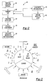
- Figure 1 is a highly schematic view of a of water production unit in which water is collected using a desiccant wheel.
- Figure 2 is a block diagram of a method of using the inventive water production unit.
- Figure 3 is a schematic view of the desiccant wheel.
- A
water production unit 10 is schematically shown in Figure 1. Theunit 10 includes anheat source 12, such as the exhaust from a vehicle, that provides heat to anair loop 14. Specifically, aheat exchanger 16 is arranged relative to theair loop 14 to heat the air within theair loop 14 using vehicle exhaust. Theunit 10 may be integrated with a mobile military vehicle, and theheat source 12 may be provided by a combustion engine that propels the vehicle. The heat source may also be provided by a stationary power plant or electrical heaters. - A
first passage 18 provides a dry air passage arranged downstream and in fluid communication with theheat exchanger 16. Adesiccant wheel 20 is arranged downstream and in fluid communication with thefirst passage 18 and upstream of asecond passage 28 that provides a humidified air passage. - The
desiccant wheel 20 is arranged in ahousing 24 and is rotated slowly about an axis by amotor 22. A controller (not shown) may be connected to themotor 22 and various sensors (not shown) to monitor the operation of theunit 10 and provide a desired output of water. Thehousing 24 includes ducting 26, which is used to maintain generally closed communication between the first andsecond passages desiccant wheel 20 to process air, such as ambient air, having moisture. - Referring to Figures 1 and 3, the
desiccant wheel 20 is constructed from a suitable material that adsorbs and desorbs water in a desired manner. A portion of thedesiccant wheel 20 exposed to the process air adsorbs moisture thereby loading the exposed portion with water. The loaded portion of thedesiccant wheel 20 is slowly rotated into theair loop 14 exposing amoist side 31 to thesecond passage 28 and the dry side to thefirst passage 18. Heated air from the heat exchanger flows from thefirst passage 18 to thesecond passage 28 desorbing the moisture and regenerating thedesiccant wheel 20. The regenerateddesiccant wheel 20 rotates to again expose the desiccant, which has adry side 29, to the process air where it can efficiently adsorb additional moisture. Thus, thedesiccant wheel 20 continually adsorbs and desorbs moisture. The adsorb and regeneration airflows can be either parallel or countercurrent (parallel shown) depending on the desired performance. - The moist air in the
second passage 28 flows to acondenser 30, which is exposed to, for example, ambient air, to produce condensate. The condensate flows through apipe 32 into astorage container 34 from which it may receive additional processing at awater treatment device 36. Air from thecondenser 30, which has been removed of water, flows back to theheat exchanger 16 through a recirculation air passage that is provided by third andfourth passages fan 40 is arranged between the third andfourth passages air loop 14 is generally considered to be a closed loop system in which the same air is circulated through theair loop 14 to pick up moisture from thedesiccant wheel 20 and deliver it to thestorage container 34. - The method of operation of the
unit 10 is depicted in a flow chart shown in Figure 2. Themethod 44 includes heating air within theair loop 14 using anexhaust source 12, as indicated atblock 46. The heated air is humidified, as indicated atblock 48. Specifically, adesiccant wheel 20 is loaded with moisture, as indicated atblock 50. The moisture-ladendesiccant wheel 20 is exposed to theair loop 14 to unload the moisture, as indicated atblock 52. The moist air is condensed, as indicated atblock 54. The condensate from thecondenser 30 is collected by astorage container 34, as indicated atblock 56. The air from theair loop 14, which has the water removed, circulates back to theheat exchanger 16 to be heated. - Although a preferred embodiment of this invention has been disclosed, a worker of ordinary skill in this art would recognize that certain modifications would come within the scope of this invention. For that reason, the following claims should be studied to determine the true scope and content of this invention.
Claims (17)
- A water production unit (10) comprising:an air loop (14) having a dry air passage (18) in fluid communication with a humidified air passage (28);a desiccant wheel (20) arranged in fluid communication between the passages (18,28), the desiccant wheel (20) having dry and moist sides (29,31), the dry and moist sides respectively exposed to the dry and humidified air passages (18,28), the desiccant wheel (20) adapted to expose the dry side (29) to an air source having moisture; anda heat exchanger (16) in fluid communication the dry side (29) for regenerating the desiccant wheel (20), the heat exchanger adapted to be exposed to regeneration heat source (12) for providing heat to said dry air passage (18).
- The water production unit according to claim 1, wherein the heat exchanger (16) is upstream from the dry air passage (18), and the desiccant wheel (20) is downstream from the dry air passage (18).
- The water production unit according to claim 2, wherein a condenser (30) is in fluid communication with and downstream from the desiccant wheel (20), the humidified air passage (28) fluidly interconnecting the desiccant wheel (20) and the condenser (30).
- The water production unit according to claim 3, wherein a recirculation passage (38,42) is arranged downstream from the condenser (30), the recirculation passage (38,42) fluidly interconnecting the condenser (30) and the heat exchanger (16).
- The water production unit according to claim 4, wherein a recirculation fan (40) is arranged in the recirculation passage (38,42) for circulating air within the air loop (14).
- The water production unit according to claim 3, 4 or 5, wherein a storage container (34) is in fluid communication with the condenser (30), the storage container (34) collecting condensate from the condenser (30).
- The water production unit according to claim 6, wherein a water treatment device is in fluid communication with the storage container (34) for removing impurities from the condensate.
- The water production unit according to any preceding claim, wherein the heat exchanger (16) regenerates the desiccant wheel (20) on the dry side, the desiccant wheel (20) rotating from the dry side (29) to the air source before returning to the moist side (31).
- The water production unit according to any preceding claim, wherein the regeneration heat source is provided by exhaust heat from a mobile vehicle.
- A method of producing water comprising the steps of:a) circulating air through an air loop (14);b) exposing a moist desiccant wheel (20) to the air loop (14);c) collecting water from the desiccant wheel (20); andd) regenerating the desiccant wheel (20) with heat from an exhaust source (12).
- The method according to claim 10, wherein the air loop (14) includes the desiccant wheel (20), a heat exchanger (16) and a condenser (30).
- The method according to claim 11, wherein the exhaust source is in communication with the heat exchanger.
- The method according to claim 12, wherein the exhaust source (12) is a vehicle exhaust.
- The method according to any of claims 10 to 13, comprising the step of adsorbing water from a process air with the desiccant wheel (20) prior to performing step b).
- The method according to any of claims 10 to 14, wherein step c) includes desorbing water from the desiccant wheel (20).
- The method according to claim 15, wherein steps c) and d) are performed simultaneously in response to exposure of the desiccant wheel (20) to heat from the exhaust source.
- The method according to any of claims 10 to 16, wherein step c) includes purifying the collected water.
Applications Claiming Priority (1)
| Application Number | Priority Date | Filing Date | Title |
|---|---|---|---|
| US68773705P | 2005-06-06 | 2005-06-06 |
Publications (2)
| Publication Number | Publication Date |
|---|---|
| EP1731208A2 true EP1731208A2 (en) | 2006-12-13 |
| EP1731208A3 EP1731208A3 (en) | 2010-04-07 |
Family
ID=36869890
Family Applications (1)
| Application Number | Title | Priority Date | Filing Date |
|---|---|---|---|
| EP06252917A Withdrawn EP1731208A3 (en) | 2005-06-06 | 2006-06-06 | Water-from-air system using desiccant wheel and exhaust |
Country Status (2)
| Country | Link |
|---|---|
| US (1) | US7251945B2 (en) |
| EP (1) | EP1731208A3 (en) |
Families Citing this family (41)
| Publication number | Priority date | Publication date | Assignee | Title |
|---|---|---|---|---|
| US7601206B2 (en) * | 2006-08-22 | 2009-10-13 | Mesosystems Technology, Inc. | Method and apparatus for generating water using an energy conversion device |
| SI2500261T1 (en) | 2007-08-09 | 2017-09-29 | Lta Corporation | Lenticular Airship and Associated Controls |
| US8894002B2 (en) | 2010-07-20 | 2014-11-25 | Lta Corporation | System and method for solar-powered airship |
| US8043414B2 (en) * | 2008-03-17 | 2011-10-25 | Industrial Technology Research Institute | Method and apparatus for desorption and dehumidifier using the same |
| JP2010158661A (en) * | 2009-01-12 | 2010-07-22 | Ind Technol Res Inst | Desorption device with low energy consumption and dehumidifying device thereof |
| US8118912B2 (en) * | 2009-09-05 | 2012-02-21 | Felix Rodriguez | Low power atmospheric water generator |
| US7905097B1 (en) | 2009-10-05 | 2011-03-15 | Hamilton Sundstrand Corporation | Water-from-air system using a desiccant wheel |
| US8747530B2 (en) | 2011-02-15 | 2014-06-10 | Lta Corporation | Systems for water extraction from air |
| US8899061B2 (en) | 2011-09-23 | 2014-12-02 | R4 Ventures, Llc | Advanced multi-purpose, multi-stage evaporative cold water/cold air generating and supply system |
| US8857204B2 (en) | 2011-09-23 | 2014-10-14 | R4 Ventures Llc | Real time individual electronic enclosure cooling system |
| WO2014164799A1 (en) * | 2013-03-12 | 2014-10-09 | Munters Corporation | Water extractor |
| AU2014377667A1 (en) | 2013-11-04 | 2016-05-19 | Lta Corporation | Cargo airship |
| US9795919B2 (en) * | 2014-03-21 | 2017-10-24 | 2525 Group, Inc. | Recycling of waste heat by dehumidifier appliance: apparatus and method |
| CN113368656B (en) | 2014-11-20 | 2024-03-19 | 代表亚利桑那大学的亚利桑那校董事会 | System and method for generating liquid water from air |
| WO2016147819A1 (en) * | 2015-03-19 | 2016-09-22 | 株式会社デンソー | Humidifying system and vehicular air conditioning system |
| CN107405986B (en) * | 2015-03-19 | 2019-08-20 | 株式会社电装 | Humidifier, air conditioner for vehicles |
| JP2018089988A (en) * | 2015-04-09 | 2018-06-14 | 株式会社デンソー | Humidifier and air conditioner for vehicle |
| WO2016187709A1 (en) * | 2015-05-22 | 2016-12-01 | Simon Fraser University | Hybrid atmospheric water generator |
| TWI718284B (en) | 2016-04-07 | 2021-02-11 | 美商零質量純水股份有限公司 | Solar thermal unit |
| CN109641173B (en) | 2016-05-20 | 2022-04-15 | 环球源公司 | System and method for water extraction control |
| EP4194763B1 (en) | 2017-04-18 | 2026-03-11 | Nortek Air Solutions Canada, Inc. | System and method for managing conditions in enclosed space |
| DE102017108170A1 (en) | 2017-04-18 | 2018-10-18 | Hochschule Karlsruhe-Technik Und Wirtschaft | Water extraction device and method for obtaining water |
| EP3612771B1 (en) | 2017-04-18 | 2023-03-22 | Nortek Air Solutions Canada, Inc. | Desiccant enhanced evaporative cooling systems and methods |
| MY206477A (en) | 2017-07-14 | 2024-12-18 | Source Global Pbc | Systems for controlled treatment of water with ozone and related methods therefor |
| MX2020002482A (en) | 2017-09-05 | 2021-02-15 | Zero Mass Water Inc | Systems and methods for managing production and distribution of liquid water extracted from air. |
| WO2019050861A1 (en) | 2017-09-05 | 2019-03-14 | Zero Mass Water, Inc. | Systems and methods to produce liquid water extracted from air |
| AU2018346803B2 (en) | 2017-10-06 | 2024-03-14 | Source Global, PBC | Systems for generating water with waste heat and related methods therefor |
| SG11202005334RA (en) | 2017-12-06 | 2020-07-29 | Zero Mass Water Inc | Systems for constructing hierarchical training data sets for use with machine-learning and related methods therefor |
| US11123682B2 (en) | 2017-12-14 | 2021-09-21 | University Of Florida Research Foundation, Incorporated | Liquid desiccant based dehumidification and cooling system |
| WO2019161339A1 (en) | 2018-02-18 | 2019-08-22 | Zero Mass Water, Inc. | Systems for generating water for a container farm and related methods therefor |
| DE102018205890A1 (en) | 2018-04-18 | 2019-10-24 | Röchling Automotive SE & Co. KG | Continuous water extraction device for a motor vehicle |
| WO2019217974A1 (en) | 2018-05-11 | 2019-11-14 | Zero Mass Water, Inc. | Systems for generating water using exogenously generated heat, exogenously generated electricity, and exhaust process fluids and related methods therefor |
| CZ2018337A3 (en) | 2018-07-08 | 2019-07-10 | České vysoké učenà technické v Praze | Equipment for extracting water from ambient air with the possibility of autonomous operation |
| US11285435B2 (en) | 2018-10-19 | 2022-03-29 | Source Global, PBC | Systems and methods for generating liquid water using highly efficient techniques that optimize production |
| US20200124566A1 (en) | 2018-10-22 | 2020-04-23 | Zero Mass Water, Inc. | Systems and methods for detecting and measuring oxidizing compounds in test fluids |
| AU2020262259B2 (en) | 2019-04-22 | 2025-09-11 | Source Global, PBC | Water vapor adsorption air drying system and method for generating liquid water from air |
| CZ2020126A3 (en) * | 2020-03-10 | 2021-01-27 | České vysoké učenà technické v Praze | Compact device for obtaining water from the air |
| US12312265B2 (en) | 2020-10-27 | 2025-05-27 | Source Global, PBC | Systems and methods for water treatment and storage |
| US11814820B2 (en) | 2021-01-19 | 2023-11-14 | Source Global, PBC | Systems and methods for generating water from air |
| USD1094637S1 (en) | 2021-04-21 | 2025-09-23 | Source Global, PBC | Water generation panel |
| WO2023059834A1 (en) | 2021-10-08 | 2023-04-13 | Source Global, PBC | Systems and methods for water production, treatment, adjustment and storage |
Family Cites Families (17)
| Publication number | Priority date | Publication date | Assignee | Title |
|---|---|---|---|---|
| SE345813B (en) * | 1969-12-01 | 1972-06-12 | Munters C | |
| US4409006A (en) * | 1981-12-07 | 1983-10-11 | Mattia Manlio M | Removal and concentration of organic vapors from gas streams |
| US4926618A (en) * | 1989-01-03 | 1990-05-22 | Charles Ratliff | Industrial dehumidifier |
| US5170633A (en) * | 1991-06-24 | 1992-12-15 | Amsted Industries Incorporated | Desiccant based air conditioning system |
| US5512083A (en) * | 1993-10-25 | 1996-04-30 | Uop | Process and apparatus for dehumidification and VOC odor remediation |
| CH691349A5 (en) * | 1995-03-16 | 2001-07-13 | Gunnar Ankarstig | Continuous drying of air to low dew point comprises combining refrigeration circuit with regenerative sorption dehumidifier |
| US6018953A (en) * | 1996-02-12 | 2000-02-01 | Novelaire Technologies, L.L.C. | Air conditioning system having indirect evaporative cooler |
| US5732562A (en) * | 1996-08-13 | 1998-03-31 | Moratalla; Jose M. | Method and apparatus for regenerating desiccants in a closed cycle |
| US6029462A (en) * | 1997-09-09 | 2000-02-29 | Denniston; James G. T. | Desiccant air conditioning for a motorized vehicle |
| SG104251A1 (en) * | 1998-01-26 | 2004-06-21 | Kankyo Co Ltd | Method and apparatus for dehumidifying air |
| US5878590A (en) * | 1998-02-25 | 1999-03-09 | General Motors Corporation | Dehumidifying mechanism for auto air conditioner with improved space utilization and thermal efficiency |
| JP2001205045A (en) * | 2000-01-25 | 2001-07-31 | Tokyo Electric Power Co Inc:The | Carbon dioxide removal method and carbon dioxide removal device |
| JP4703889B2 (en) * | 2000-06-05 | 2011-06-15 | 富士フイルム株式会社 | Method for circulating concentration treatment of dry type dehumidifier regeneration gas |
| US7077187B2 (en) * | 2001-08-30 | 2006-07-18 | Hydrogenics Corporation | Apparatus for exchanging energy and/or mass |
| KR100487381B1 (en) * | 2002-12-26 | 2005-05-03 | 엘지전자 주식회사 | air conditioning system ventilating room |
| US6854279B1 (en) * | 2003-06-09 | 2005-02-15 | The United States Of America As Represented By The Secretary Of The Navy | Dynamic desiccation cooling system for ships |
| US6973795B1 (en) * | 2004-05-27 | 2005-12-13 | American Standard International Inc. | HVAC desiccant wheel system and method |
-
2005
- 2005-08-09 US US11/199,979 patent/US7251945B2/en not_active Expired - Fee Related
-
2006
- 2006-06-06 EP EP06252917A patent/EP1731208A3/en not_active Withdrawn
Non-Patent Citations (1)
| Title |
|---|
| None |
Also Published As
| Publication number | Publication date |
|---|---|
| EP1731208A3 (en) | 2010-04-07 |
| US7251945B2 (en) | 2007-08-07 |
| US20060272344A1 (en) | 2006-12-07 |
Similar Documents
| Publication | Publication Date | Title |
|---|---|---|
| US7251945B2 (en) | Water-from-air system using desiccant wheel and exhaust | |
| US7601208B2 (en) | Water-from-air using liquid desiccant and vehicle exhaust | |
| US4197713A (en) | Process and plant for the recovery of water from humid air | |
| US7601206B2 (en) | Method and apparatus for generating water using an energy conversion device | |
| KR20100110645A (en) | Air drier system with heat source by the oil separating document | |
| WO2004052508A1 (en) | Temperature swing humidity collector using powerplant waste heat for regeneration of adsorbent | |
| JP2010529398A5 (en) | ||
| JP5790764B2 (en) | Air purification equipment for vehicles | |
| EP3513861B1 (en) | Hybrid low dew point compressed air dryer | |
| US20240350963A1 (en) | Gas sorption system | |
| CN101228398B (en) | method of cooling air flow | |
| CN114719459A (en) | Deep dehumidification system driven by cascade heat pump and its application | |
| US7125439B2 (en) | Air environment control system and technique | |
| US8414691B2 (en) | System and method extracting and employing compression heat in biogas treatment plant equipment | |
| JP2012139657A (en) | Solvent-recovering system | |
| JP3305977B2 (en) | Feed air dehumidification and cooling system in feed air multistage compressor | |
| JP4642189B2 (en) | Desiccant air conditioning system | |
| CN101747948B (en) | Treatment process for dehumidifying combustible gases in expansion way | |
| KR20230135869A (en) | An air drying system for removing moisture contained in compressed air generated by an air compressor | |
| JP7842138B2 (en) | Gas treatment device | |
| CN222824481U (en) | A dehumidification system | |
| US20210039042A1 (en) | Atoms power - fully integrated water, climate control and energy production system | |
| CN210892422U (en) | Engine fan blade lubrication drying equipment | |
| CN118998860A (en) | Energy-saving rotary dehumidifier | |
| WO2024105394A1 (en) | Atmospheric water generator |
Legal Events
| Date | Code | Title | Description |
|---|---|---|---|
| PUAI | Public reference made under article 153(3) epc to a published international application that has entered the european phase |
Free format text: ORIGINAL CODE: 0009012 |
|
| AK | Designated contracting states |
Kind code of ref document: A2 Designated state(s): AT BE BG CH CY CZ DE DK EE ES FI FR GB GR HU IE IS IT LI LT LU LV MC NL PL PT RO SE SI SK TR |
|
| AX | Request for extension of the european patent |
Extension state: AL BA HR MK YU |
|
| PUAL | Search report despatched |
Free format text: ORIGINAL CODE: 0009013 |
|
| AK | Designated contracting states |
Kind code of ref document: A3 Designated state(s): AT BE BG CH CY CZ DE DK EE ES FI FR GB GR HU IE IS IT LI LT LU LV MC NL PL PT RO SE SI SK TR |
|
| AX | Request for extension of the european patent |
Extension state: AL BA HR MK RS |
|
| RIC1 | Information provided on ipc code assigned before grant |
Ipc: B01D 53/06 20060101ALI20100226BHEP Ipc: B01D 5/00 20060101AFI20060828BHEP |
|
| 17P | Request for examination filed |
Effective date: 20100722 |
|
| 17Q | First examination report despatched |
Effective date: 20100913 |
|
| AKX | Designation fees paid |
Designated state(s): DE FR GB IT |
|
| GRAP | Despatch of communication of intention to grant a patent |
Free format text: ORIGINAL CODE: EPIDOSNIGR1 |
|
| INTG | Intention to grant announced |
Effective date: 20131004 |
|
| STAA | Information on the status of an ep patent application or granted ep patent |
Free format text: STATUS: THE APPLICATION IS DEEMED TO BE WITHDRAWN |
|
| 18D | Application deemed to be withdrawn |
Effective date: 20140217 |