EP1729543A1 - Display apparatus with backlight driver control - Google Patents
Display apparatus with backlight driver control Download PDFInfo
- Publication number
- EP1729543A1 EP1729543A1 EP06114552A EP06114552A EP1729543A1 EP 1729543 A1 EP1729543 A1 EP 1729543A1 EP 06114552 A EP06114552 A EP 06114552A EP 06114552 A EP06114552 A EP 06114552A EP 1729543 A1 EP1729543 A1 EP 1729543A1
- Authority
- EP
- European Patent Office
- Prior art keywords
- backlight
- voltage
- driving power
- display apparatus
- drive
- Prior art date
- Legal status (The legal status is an assumption and is not a legal conclusion. Google has not performed a legal analysis and makes no representation as to the accuracy of the status listed.)
- Withdrawn
Links
Images


Classifications
-
- G—PHYSICS
- G02—OPTICS
- G02F—OPTICAL DEVICES OR ARRANGEMENTS FOR THE CONTROL OF LIGHT BY MODIFICATION OF THE OPTICAL PROPERTIES OF THE MEDIA OF THE ELEMENTS INVOLVED THEREIN; NON-LINEAR OPTICS; FREQUENCY-CHANGING OF LIGHT; OPTICAL LOGIC ELEMENTS; OPTICAL ANALOGUE/DIGITAL CONVERTERS
- G02F1/00—Devices or arrangements for the control of the intensity, colour, phase, polarisation or direction of light arriving from an independent light source, e.g. switching, gating or modulating; Non-linear optics
- G02F1/01—Devices or arrangements for the control of the intensity, colour, phase, polarisation or direction of light arriving from an independent light source, e.g. switching, gating or modulating; Non-linear optics for the control of the intensity, phase, polarisation or colour
- G02F1/13—Devices or arrangements for the control of the intensity, colour, phase, polarisation or direction of light arriving from an independent light source, e.g. switching, gating or modulating; Non-linear optics for the control of the intensity, phase, polarisation or colour based on liquid crystals, e.g. single liquid crystal display cells
- G02F1/133—Constructional arrangements; Operation of liquid crystal cells; Circuit arrangements
-
- G—PHYSICS
- G09—EDUCATION; CRYPTOGRAPHY; DISPLAY; ADVERTISING; SEALS
- G09G—ARRANGEMENTS OR CIRCUITS FOR CONTROL OF INDICATING DEVICES USING STATIC MEANS TO PRESENT VARIABLE INFORMATION
- G09G3/00—Control arrangements or circuits, of interest only in connection with visual indicators other than cathode-ray tubes
- G09G3/20—Control arrangements or circuits, of interest only in connection with visual indicators other than cathode-ray tubes for presentation of an assembly of a number of characters, e.g. a page, by composing the assembly by combination of individual elements arranged in a matrix no fixed position being assigned to or needed to be assigned to the individual characters or partial characters
- G09G3/34—Control arrangements or circuits, of interest only in connection with visual indicators other than cathode-ray tubes for presentation of an assembly of a number of characters, e.g. a page, by composing the assembly by combination of individual elements arranged in a matrix no fixed position being assigned to or needed to be assigned to the individual characters or partial characters by control of light from an independent source
- G09G3/3406—Control of illumination source
-
- H—ELECTRICITY
- H05—ELECTRIC TECHNIQUES NOT OTHERWISE PROVIDED FOR
- H05B—ELECTRIC HEATING; ELECTRIC LIGHT SOURCES NOT OTHERWISE PROVIDED FOR; CIRCUIT ARRANGEMENTS FOR ELECTRIC LIGHT SOURCES, IN GENERAL
- H05B45/00—Circuit arrangements for operating light-emitting diodes [LED]
- H05B45/50—Circuit arrangements for operating light-emitting diodes [LED] responsive to malfunctions or undesirable behaviour of LEDs; responsive to LED life; Protective circuits
-
- G—PHYSICS
- G09—EDUCATION; CRYPTOGRAPHY; DISPLAY; ADVERTISING; SEALS
- G09G—ARRANGEMENTS OR CIRCUITS FOR CONTROL OF INDICATING DEVICES USING STATIC MEANS TO PRESENT VARIABLE INFORMATION
- G09G2330/00—Aspects of power supply; Aspects of display protection and defect management
- G09G2330/02—Details of power systems and of start or stop of display operation
- G09G2330/021—Power management, e.g. power saving
-
- G—PHYSICS
- G09—EDUCATION; CRYPTOGRAPHY; DISPLAY; ADVERTISING; SEALS
- G09G—ARRANGEMENTS OR CIRCUITS FOR CONTROL OF INDICATING DEVICES USING STATIC MEANS TO PRESENT VARIABLE INFORMATION
- G09G2330/00—Aspects of power supply; Aspects of display protection and defect management
- G09G2330/04—Display protection
- G09G2330/045—Protection against panel overheating
-
- H—ELECTRICITY
- H05—ELECTRIC TECHNIQUES NOT OTHERWISE PROVIDED FOR
- H05B—ELECTRIC HEATING; ELECTRIC LIGHT SOURCES NOT OTHERWISE PROVIDED FOR; CIRCUIT ARRANGEMENTS FOR ELECTRIC LIGHT SOURCES, IN GENERAL
- H05B45/00—Circuit arrangements for operating light-emitting diodes [LED]
- H05B45/50—Circuit arrangements for operating light-emitting diodes [LED] responsive to malfunctions or undesirable behaviour of LEDs; responsive to LED life; Protective circuits
- H05B45/56—Circuit arrangements for operating light-emitting diodes [LED] responsive to malfunctions or undesirable behaviour of LEDs; responsive to LED life; Protective circuits involving measures to prevent abnormal temperature of the LEDs
Definitions
- the present invention relates to a display apparatus having a backlight such as a light emitting diode (LED).
- a backlight such as a light emitting diode (LED).
- Display apparatuses have increasingly employed one or more light emitting diodes as a backlight to improve colour realization, instead of employing a conventional cold cathode fluorescent lamp (CCFL).
- CCFL cold cathode fluorescent lamp
- a display apparatus having backlight that uses an LED element improves the colour realization, due in part to the LED backlight.
- the conventional display apparatus comprises a backlight driver to drive the LED backlight. If driving power, for example, 160V, is supplied to the backlight driver to drive the LED backlight, the backlight driver outputs a control signal to the LED backlight by using the supplied driving power.
- the display apparatus may, however, supply a driving power at a lower voltage than normal (for example, (160-x)V), to the backlight driver, due to operation changes or errors.
- the backlight driver is characterized by generating a constant current from the driving power to control the drive of the LED backlight, the backlight driver draws more current from the driving power in proportion to the lowered voltage of the supplied driving power.
- the LED element of the LED backlight generates more heat as more current is drawn by the backlight driver to compensate for the reduced voltage to maintain a constant current output.
- an over-current protection circuit of a switching mode power supply (SMPS) in the display apparatus operates, thereby turning off the power of the display apparatus.
- SMPS switching mode power supply
- the entire power supply of the display apparatus is turned off to prevent the LED backlight from being damaged or deteriorating.
- the conventional display apparatus turns off the entire power supply if the backlight driver generates the over-current, a user is required to reboot the display apparatus to use it. Also, a user may become confused while using the display apparatus as he/she does not recognize why the power of the display has been turned off.
- the invention provides a display apparatus as claimed in claim 1. Further features and advantages of the invention will be evident from claim 2 et seq.
- a display apparatus comprising a light emitting diode (LED) backlight, a backlight driver to drive the LED backlight, a power supplier to supply driving power to the backlight driver, a detector to detect a voltage of the driving power supplied to the backlight driver and determine whether the voltage of the driving power is lower than a predetermined voltage, and a controller to control at least one of the backlight driver and the power supplier to disable the drive of the LED backlight if it is determined that the voltage of the driving power is lower than the predetermined voltage based on the detection of the detector.
- LED light emitting diode
- the controller comprises a field programmable gate array (FPGA) to control the backlight driver to disable the drive of the LED backlight if it is determined that the voltage of the driving power is lower than the predetermined voltage based on the detection of the detector.
- FPGA field programmable gate array
- the backlight driver disables the drive of the LED backlight according to a disable control of the FPGA.
- the controller comprises a microcomputer to control the power supplier to cut off the driving power supplied to the backlight driver to disable the drive of the LED backlight if it is determined that the voltage of the driving power is lower than the predetermined voltage based on the detection of the detector.
- the microcomputer controls the power supplier to cut off the driving power supplied to the backlight driver to disable the drive of the LED backlight if the determination that the voltage of the driving power is lower than the predetermined voltage, is generated for a predetermined number of periods of time, with the predetermined number of times based on the detection of the detector.
- the microcomputer controls the power supplier to change a driving mode of the display apparatus into a standby mode to disable the drive of the LED backlight.
- the detector comprises a comparator to detect the voltage of the driving power supplied to the backlight driver, compare the detected voltage with the predetermined reference voltage, and output a high signal to the controller if the voltage of the driving power is lower than the reference voltage.
- the display apparatus further comprises an informer to inform a user of an over-temperature of the LED backlight, wherein the controller controls the informer to inform the user of the over-temperature of the LED backlight if and/or when disabling the drive of the LED backlight based on the detection of the detector.
- the controller controls the informer to inform a user of a normal temperature of the LED backlight if it is determined that the voltage of the driving power is higher than the predetermined voltage based on the detection of the detector while in a state wherein the drive of the LED backlight is disabled.
- the informer comprises at least one of an on screen display (OSD) generator to generate an OSD over-temperature message and an OSD normal temperature message, and a melody generator to generate an over-temperature melody and a normal temperature melody to inform a user of the over-temperature and normal temperature of the LED backlight.
- OSD on screen display
- melody generator to generate an over-temperature melody and a normal temperature melody to inform a user of the over-temperature and normal temperature of the LED backlight.
- FIG. 1 is a control block diagram of a display apparatus according to a first exemplary embodiment of the present invention.
- the display apparatus according to the first embodiment of the present invention comprises an LED backlight 20, a backlight driver 30 to control the drive of the LED backlight 20, a power supplier 10' to supply driving power, for example, 160V, to the backlight driver 30, a detector 40 to detect a voltage of the driving power supplied to the backlight driver 30 and determine whether the voltage of the driving power is lower than a predetermined voltage, and a controller 50" to control at least one of the backlight driver 30 and the power supplier 10' to disable the drive of the LED backlight 20 if it is determined that the voltage of the driving power is lower than the predetermined voltage based on the detection of the detector 40.
- the LED backlight 20 may comprise a plurality of LED parts 20a, for example, a first LED part, to an Nth LED part, which comprise a plurality of LED elements (not all shown) respectively.
- the power supplier 10' respectively supplies the driving power to various circuits (not shown) to perform functions in the display apparatus, as well as supplies the driving power, for example, 160V, to the backlight driver 30.
- the backlight driver 30 generates a constant current from the driving power supplied from the power supplier 10', and applies the constant current to the LED backlight 20 to control the drive of the LED backlight 20. If the backlight driver 30 receives a disable signal from the controller 50", the backlight driver 30 disables the current applied to the LED backlight 20 to make the current supplied to the LED backlight 20 become substantially "0", thereby disabling the drive of the LED backlight 20. If the backlight driver 30 receives an enable signal from the controller 50", the backlight driver 30 may control the drive of the LED backlight 20 to drive it normally.
- the detector 40 detects the voltage of the driving power supplied to the backlight driver 30, and determines whether the voltage of the driving power is lower than a predetermined voltage.
- the detector 40 comprises a voltage divider, or resistance division circuit including resistors R1 and R2 to provide a predetermined fraction of the driving power voltage for comparison by using the driving power, for example, 160V, supplied to the backlight driver 30, and a comparator 45 to compare a voltage of the predetermined comparison driving power detected through the resistance division circuit of R1 and R2 with a predetermined reference voltage V1, and output a high signal if the voltage of the predetermined comparison driving power is lower than the reference voltage V1.
- the controller 50" comprises a field programmable gate array (FPGA) 52 as a controller to control the backlight driver 30 to disable the drive of the LED backlight 20 by outputting the disable signal to the backlight driver 30 if it is determined that the controller 50" receives the high signal from the comparator 45, that is, if the voltage of the predetermined comparison driving power is lower than the reference voltage V1 on the basis of the detection of the detector 40.
- FPGA field programmable gate array
- the FPGA 52 controls the backlight driver 30 to enable the drive of the LED backlight 20 by outputting the enable signal to the backlight driver 30 if it is determined that the voltage of the predetermined comparison driving power is larger than the reference voltage V1, that is, if a low signal is input from the comparator 45 based on the detection of the detector 40 while in a state wherein the drive of the LED backlight 20 is disabled.
- the backlight driver 30 disables the drive of the LED backlight 20 preferably only if the driving power supplied to the backlight driver 30 is lowered below a predetermined allowable value of the normal driving power, for example, 160V, instead of turning off the entire power of the display apparatus as done conventionally.
- the backlight driver 30 disables the drive of the LED backlight 20 if the driving power supplied to the backlight driver 30 is lowered below and/or increased above a predetermined range of allowable values of the normal driving power, for example, (160 ⁇ n)V, or is lowered below and/or increased above an allowable value or range of values of the normal driving power for a period of elapsed time.
- the controller 50" comprises a microcomputer 55 to output a PWM signal to the power supplier 10' to control the power supplier 10' and cut off the driving power supplied to the backlight driver 30 and disable the drive of the LED backlight 20 if the high signal is input from the comparator 45 based on the detection of the detector 40.
- the microcomputer 55 outputs the PWM signal to the power supplier 10' to control the power supplier 10' and change a driving mode of the display apparatus into a standby mode, and cuts off the driving power supplied to the backlight driver 30 if the high signal is input from the comparator 45 based on the detection of the detector 40.
- the microcomputer 55 controls the power supplier 10' in a pulse wide modulation (PWM) method to then supply the driving power to the backlight driver 30 or change the driving mode of the display apparatus into the normal mode, thereby enabling the drive of the LED backlight 20.
- PWM pulse wide modulation
- the backlight driver 30 is preferably disabled through an operation of the FPGA 52 to make the current applied to the LED backlight 20 become substantially "0". Also, the drive of the LED backlight 20 may be disabled by changing the driving mode of the display apparatus into the standby mode or by cutting off the power supplied to the backlight driver 30.
- the display apparatus further comprises an informer 60 to inform a user of the over-temperature of the LED backlight 20.
- the controller 50" may control the informer 60 to inform the user of the over-temperature of the LED backlight 20 if and/or when disabling the drive of the LED backlight 20 based on the detection of the detector 40.
- the informer 60 may comprise at least one of an on screen display (OSD) generator 62 to generate an OSD over-temperature message and an OSD normal temperature message to inform the user of the over-temperature and normal temperature of the LED backlight 20, and a melody generator 65 to generate an over-temperature melody and a normal temperature melody to inform the user of the over-temperature and the normal temperature of the LED backlight 20.
- OSD on screen display
- melody generator 65 to generate an over-temperature melody and a normal temperature melody to inform the user of the over-temperature and the normal temperature of the LED backlight 20.
- the microcomputer 55 may further control at least one of the OSD generator 62 and the melody generator 65 to inform the user of the over-temperature of the LED backlight 20 if and/or when disabling the drive of the LED backlight 20. Also, the microcomputer 55 may control at least one of the OSD generator 62 and the melody generator 65 to inform the user of the normal temperature of the LED backlight 20 if it is determined that the voltage of the predetermined comparison driving power is higher than the reference voltage V1 based on the detection of the detector 40 while in a state wherein the drive of the LED backlight 20 is disabled.
- the controller 50" comprises both the FPGA 52 and the microcomputer 55, but is not limited thereto.
- the controller 50" may comprise only one of the FPGA 52 and the microcomputer 55, as shown in FIG. 2.
- a second embodiment of the present invention will now be described with reference to FIGS. 2 through 5.
- FIG. 2 is a control block diagram of a display apparatus according to a second exemplary embodiment of the present invention.
- the display apparatus according to the second embodiment of the present invention comprises the LED backlight 20, the backlight driver 30 to control the drive of the LED backlight 20, a power supplier 10 to supply driving power, for example, 160V, to the backlight driver 30, the detector 40 to detect a voltage of the driving power supplied to the backlight driver 30 and determine whether the voltage of the driving power is lower than a predetermined voltage, and a controller 50 to control the backlight driver 30 to disable the drive of the LED backlight 20 if it is determined that the voltage of the driving power is lower than the predetermined voltage based on the detection of the detector 40.
- driving power for example, 160V
- the backlight driver 30 may disable a current applied to the LED backlight 20 to make it substantially "0", thereby disabling the drive of the LED backlight 20. If an enable signal is input from the controller 50, the backlight driver 30 may control the drive of the LED backlight 20 to drive it normally.
- the controller 50 comprises the field programmable gate array 52 as a controller to control the backlight driver 30 to disable the drive of the LED backlight 20 by outputting the disable signal to the backlight driver 30 if a high signal is input from the comparator 45.
- the FPGA 52 may control the backlight driver 30 to enable the drive of the LED backlight 20 by outputting the enable signal to the backlight driver 30 if a low signal is input from the comparator 45 while in a state wherein the drive of the LED backlight 20 is disabled.
- the backlight driver 30 may be disabled through an operation of the FPGA 52.
- the LED backlight 20 is driven in a normal mode at operation S10.
- the comparator 45 determines whether the voltage detected through the resistance division circuit resistors R1 and R2 is lower than the predetermined reference voltage V1, and if so supplies a high signal to the FPGA 52. Otherwise the comparator 45 supplies a low signal. If the high signal is input from the comparator 45, this menas that the voltage from the power supplier 11 has dropped below a threshold value and the FPGA 52 then outputs a disable signal to the backlight driver 30 at operation S30.
- the backlight driver 30 then controls the current applied to the LED backlight 20 to become substantially "0", thereby disabling the drive of the LED backlight 20 at operation S40.
- the FPGA 52 continuously determines whether the voltage of the predetermined comparison driving power is lower than the predetermined reference voltage V1, according to the high and low signals input from the comparator 45 at operation S50.
- the FPGA 52 outputs the enable signal to the backlight driver 30 and drives the LED backlight 20 normally, returning to the operation S10, if it is determined that the voltage of the predetermined comparison driving power is no longer lower than the reference voltage V1 according to the high and low signals input from the comparator 45 while in a state wherein the drive of the LED backlight 20 is disabled (that is, after operation S40).
- the display apparatus disables the drive of the LED backlight 20 only if the driving power supplied to the backlight driver 30 is lowered below the predetermined allowable value of the normal driving power instead of turning off the entire power of the display apparatus as done conventionally.
- FIG. 3 is a control block diagram of a display apparatus according to a third exemplary embodiment of the present invention.
- the display apparatus comprises the LED backlight 20, a backlight driver 30' to control the drive of the LED backlight 20, the power supplier 10' to supply driving power, for example, 160V, to the backlight driver 30', the detector 40 to detect a voltage of the driving power supplied to the backlight driver 30' and determine whether the voltage of the driving power is lower than a predetermined voltage, and a controller 50' to control the power supplier 10' to disable the drive of the LED backlight 20 if it is determined that the voltage of the driving power is lower than the predetermined voltage based on the detection of the detector 40.
- driving power for example, 160V
- the backlight driver 30' generates a constant current from the driving power supplied from the power supplier 10', and controls the drive of the LED backlight 20 by using the constant current.
- the controller 50' comprises a microcomputer 55 to output a PWM signal to the power supplier 10' to control the power supplier 10' to cut off the driving power supplied to the backlight driver 30' if the high signal is input from the comparator 45 based on the detection of the detector 40, thereby disabling the drive of the LED backlight 20.
- the microcomputer 55 outputs the PWM signal to the power supplier 10' to control the power supplier 10' to change a driving mode of the display apparatus from a normal mode to a standby mode, and cuts off the driving power supplied to the backlight driver 30' if the high signal is input from the comparator 45.
- the driving mode of the display apparatus may be changed into the standby mode or the driving power supplied to the backlight driver 30' may be cut off, thereby disabling the drive of the LED backlight 20.
- the microcomputer 55 may control the power supplier 10' to cut off the driving power supplied to the backlight driver 30' or change the driving mode of the display apparatus into the standby mode to disable the drive of the LED backlight 20.
- the operation of the LED backlight 20 may be disabled only if the driving power is lowered below the predetermined allowable value due to operation changes or errors, and exclude occurrences wherein the driving power is lowered below the allowable value due to temporary malfunctions and normal operation power is quickly supplied again.
- the operation of disabling the drive of the LED backlight 20 is not described in the first and second exemplary embodiments in a case where the determination that the voltage of the predetermined comparison driving power is lower than the reference voltage V1, is generated for a predetermined number of periods of time.
- the microcomputer 55 or the FPGA 52 of the first embodiment, or the FPGA 52 of the second embodiment may easily operate to disable the drive of the LED backlight 20 only, if the determination that the voltage of the predetermined comparison driving power is lower than the reference voltage V1, is generated for the predetermined number of periods of time.
- the display apparatus further comprises the OSD generator 62 to generate an OSD over-temperature message and an OSD normal temperature message, and the melody generator 65 to generate an over-temperature melody and a normal temperature melody.
- the microcomputer 55 may control at least one of the OSD generator 62 and the melody generator 65 to inform the user of the over-temperature of an LED backlight 20 if and/or when disabling the drive of the LED backlight 20. Also, the microcomputer 55 may control at least one of the OSD generator 62 and the melody generator 65 to inform the user of a normal temperature of the LED backlight 20 if it is determined that a voltage of predetermined comparison driving power is higher than a reference voltage V1 based on the detection of the detector 40 while in a state wherein the drive of the LED backlight 20 is disabled.
- the display apparatus drives the LED backlight 20 in a normal mode at operation S110.
- the microcomputer 55 determines whether the voltage detected by the comparator 45 through the resistance division circuit resistors R1 and R2 is lower than the predetermined reference voltage V1 gives rise to high and low signals.
- the microcomputer 55 checks if the determination (hereinafter referred to as Case 1) that the voltage of the predetermined comparison driving power is lower than the reference voltage V1, is generated for a predetermined number of periods of time, at operation S130.
- the microcomputer 55 controls informer 60 to inform the user of the over-temperature of the LED backlight 20 in operation S132. Then, a user recognizes the over-temperature of the LED backlight 20 through the informer 60 and can select to turn off the display apparatus, thereby cooling off the LED backlight 20 at operation S137.
- the microcomputer 55 determines whether the LED backlight 20 is still driven for a predetermined number of periods of time (2 seconds) after the operation S132, at operation S135. If the user selects the power off, the LED backlight 20 is not driven. If the LED backlight 20 is being driven, the microcomputer 55 controls the power supplier 10' to change the driving mode of the display apparatus into the standby mode at operation S140. If the display apparatus is in the standby mode, the driving power supplied to the backlight driver 30' is cut off. Thus, the drive of the LED backlight is disabled.
- the microcomputer 55 continuously determines whether the voltage of the predetermined comparison driving power detected through the resistance division circuit resistors R1 and R2 is lower than the predetermined reference voltage V1 according to the high and low signals input from the comparator 45, at operation S150. If it is determined that the voltage of the predetermined comparison driving power is no longer lower than the reference voltage V1 according to the high and low signal input from the comparator 45 while in a state wherein the drive of the LED backlight 20 is disabled in the standby mode (that is, after operation S140), the microcomputer 55 controls the informer 60 to inform the user of the normal temperature of the LED backlight 20 at operation S152. The microcomputer 55 may control the power supplier 10' to then change the driving mode of the display apparatus into the normal mode, thereby driving the LED backlight 20 normally and returning to the operation S110.
- the display apparatus may be changed into the standby mode and disable the drive of the LED backlight 20 instead of turning off the entire power to the device as done conventionally if the driving power supplied to the backlight driver 30' is lowered below the predetermined allowable value of the normal driving power.
- the over-temperature and normal temperature of the LED backlight 20 a user may not feel confusion as to the cause of power interruption and may take appropriate action.
- the described embodiments of the present invention thus provide a display apparatus in which the drive of the LED backlight 20 is disabled to prevent over-current from being generated by the backlight driver 30 if the voltage of driving power supplied by the power supplier 10 to the backlight driver is lower than a predetermined value. This prevents overheating.
Landscapes
- Physics & Mathematics (AREA)
- Engineering & Computer Science (AREA)
- General Physics & Mathematics (AREA)
- Computer Hardware Design (AREA)
- Theoretical Computer Science (AREA)
- Nonlinear Science (AREA)
- Mathematical Physics (AREA)
- Chemical & Material Sciences (AREA)
- Crystallography & Structural Chemistry (AREA)
- Optics & Photonics (AREA)
- Liquid Crystal Display Device Control (AREA)
- Control Of Indicators Other Than Cathode Ray Tubes (AREA)
Abstract
Description
- The present invention relates to a display apparatus having a backlight such as a light emitting diode (LED).
- Display apparatuses have increasingly employed one or more light emitting diodes as a backlight to improve colour realization, instead of employing a conventional cold cathode fluorescent lamp (CCFL).
- A display apparatus having backlight that uses an LED element improves the colour realization, due in part to the LED backlight. However, as the display apparatus generates a large amount of heat due to the LED element, care should be taken to prevent damage or deterioration of the LED backlight.
- A conventional display apparatus having such an LED backlight will now be described. The conventional display apparatus comprises a backlight driver to drive the LED backlight. If driving power, for example, 160V, is supplied to the backlight driver to drive the LED backlight, the backlight driver outputs a control signal to the LED backlight by using the supplied driving power. The display apparatus may, however, supply a driving power at a lower voltage than normal (for example, (160-x)V), to the backlight driver, due to operation changes or errors. As the backlight driver is characterized by generating a constant current from the driving power to control the drive of the LED backlight, the backlight driver draws more current from the driving power in proportion to the lowered voltage of the supplied driving power. Thus, the LED element of the LED backlight generates more heat as more current is drawn by the backlight driver to compensate for the reduced voltage to maintain a constant current output.
- If the constant current generated by the backlight driver through the driving power reaches a predetermined level, for example, 4A, an over-current protection circuit of a switching mode power supply (SMPS) in the display apparatus operates, thereby turning off the power of the display apparatus.
- That is, if the driving power voltage, which is lower than the normal driving power voltage, is supplied to the backlight driver, and the backlight driver generates an over-current, the entire power supply of the display apparatus is turned off to prevent the LED backlight from being damaged or deteriorating.
- As the conventional display apparatus turns off the entire power supply if the backlight driver generates the over-current, a user is required to reboot the display apparatus to use it. Also, a user may become confused while using the display apparatus as he/she does not recognize why the power of the display has been turned off.
- Accordingly, a need exists for a system and method which efficiently disables the drive of an LED backlight if driving power voltage supplied to a backlight driver is lower than a predetermined voltage to prevent a backlight driver from generating an over-current condition.
- Accordingly, it is an aspect of exemplary embodiments of the present invention to substantially solve the above and other problems, and to provide a display apparatus which disables the drive of an LED backlight to prevent over-current of a backlight driver from being generated if the driving power supplied to a backlight driver is lower than a predetermined driving power.
- Broadly stated, the invention provides a display apparatus as claimed in
claim 1. Further features and advantages of the invention will be evident from claim 2 et seq. - Also, it is another aspect of embodiments of the present invention to provide a display apparatus which informs a user of an enable/disable operation of the LED backlight drive to prevent a user from becoming confused.
- Additional aspects and/or advantages of embodiments of the present invention will be set forth in part in the description which follows and, in part, will be obvious from the description, or may be learned by practice of embodiments of the present invention.
- The foregoing and/or other aspects of embodiments of the present invention are also achieved by providing a display apparatus comprising a light emitting diode (LED) backlight, a backlight driver to drive the LED backlight, a power supplier to supply driving power to the backlight driver, a detector to detect a voltage of the driving power supplied to the backlight driver and determine whether the voltage of the driving power is lower than a predetermined voltage, and a controller to control at least one of the backlight driver and the power supplier to disable the drive of the LED backlight if it is determined that the voltage of the driving power is lower than the predetermined voltage based on the detection of the detector.
- According to an aspect of embodiments of the present invention, the controller comprises a field programmable gate array (FPGA) to control the backlight driver to disable the drive of the LED backlight if it is determined that the voltage of the driving power is lower than the predetermined voltage based on the detection of the detector.
- According to an aspect of embodiments of the present invention, the backlight driver disables the drive of the LED backlight according to a disable control of the FPGA.
- According to another aspect of embodiments of the present invention, the controller comprises a microcomputer to control the power supplier to cut off the driving power supplied to the backlight driver to disable the drive of the LED backlight if it is determined that the voltage of the driving power is lower than the predetermined voltage based on the detection of the detector.
- According to another aspect of embodiments of the present invention, the microcomputer controls the power supplier to cut off the driving power supplied to the backlight driver to disable the drive of the LED backlight if the determination that the voltage of the driving power is lower than the predetermined voltage, is generated for a predetermined number of periods of time, with the predetermined number of times based on the detection of the detector.
- According to another aspect of embodiments of the present invention, the microcomputer controls the power supplier to change a driving mode of the display apparatus into a standby mode to disable the drive of the LED backlight.
- According to another aspect of embodiments of the present invention, the detector comprises a comparator to detect the voltage of the driving power supplied to the backlight driver, compare the detected voltage with the predetermined reference voltage, and output a high signal to the controller if the voltage of the driving power is lower than the reference voltage.
- According to another aspect of embodiments of the present invention, the display apparatus further comprises an informer to inform a user of an over-temperature of the LED backlight, wherein the controller controls the informer to inform the user of the over-temperature of the LED backlight if and/or when disabling the drive of the LED backlight based on the detection of the detector.
- According to another aspect of embodiments of the present invention, the controller controls the informer to inform a user of a normal temperature of the LED backlight if it is determined that the voltage of the driving power is higher than the predetermined voltage based on the detection of the detector while in a state wherein the drive of the LED backlight is disabled.
- According to another aspect of embodiments of the present invention, the informer comprises at least one of an on screen display (OSD) generator to generate an OSD over-temperature message and an OSD normal temperature message, and a melody generator to generate an over-temperature melody and a normal temperature melody to inform a user of the over-temperature and normal temperature of the LED backlight.
- The above and/or other aspects and advantages of embodiments of the present invention will become apparent and more readily appreciated from the following description, taken in conjunction with the accompanying drawings, of which:
- FIG. 1 is a control block diagram of a display apparatus according to a first exemplary embodiment of the present invention;
- FIG. 2 is a control block diagram of a display apparatus according to a second exemplary embodiment of the present invention;
- FIG. 3 is a control block diagram of a display apparatus according to a third exemplary embodiment of the present invention;
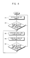
- FIG. 4 is a control flowchart of the display apparatus in FIG. 2 according to the second exemplary embodiment of the present invention; and
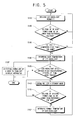
- FIG. 5 is a control flowchart of the display apparatus in FIG. 3 according to the third exemplary embodiment of the present invention.
- Throughout the drawings, like reference numerals will be understood to refer to like parts, components and structures.
- FIG. 1 is a control block diagram of a display apparatus according to a first exemplary embodiment of the present invention. As shown therein, the display apparatus according to the first embodiment of the present invention comprises an
LED backlight 20, abacklight driver 30 to control the drive of theLED backlight 20, a power supplier 10' to supply driving power, for example, 160V, to thebacklight driver 30, adetector 40 to detect a voltage of the driving power supplied to thebacklight driver 30 and determine whether the voltage of the driving power is lower than a predetermined voltage, and acontroller 50" to control at least one of thebacklight driver 30 and the power supplier 10' to disable the drive of theLED backlight 20 if it is determined that the voltage of the driving power is lower than the predetermined voltage based on the detection of thedetector 40. - The
LED backlight 20 may comprise a plurality ofLED parts 20a, for example, a first LED part, to an Nth LED part, which comprise a plurality of LED elements (not all shown) respectively. - The power supplier 10' respectively supplies the driving power to various circuits (not shown) to perform functions in the display apparatus, as well as supplies the driving power, for example, 160V, to the
backlight driver 30. - The
backlight driver 30 generates a constant current from the driving power supplied from the power supplier 10', and applies the constant current to theLED backlight 20 to control the drive of theLED backlight 20. If thebacklight driver 30 receives a disable signal from thecontroller 50", thebacklight driver 30 disables the current applied to theLED backlight 20 to make the current supplied to theLED backlight 20 become substantially "0", thereby disabling the drive of theLED backlight 20. If thebacklight driver 30 receives an enable signal from thecontroller 50", thebacklight driver 30 may control the drive of theLED backlight 20 to drive it normally. - The
detector 40 detects the voltage of the driving power supplied to thebacklight driver 30, and determines whether the voltage of the driving power is lower than a predetermined voltage. Thedetector 40 comprises a voltage divider, or resistance division circuit including resistors R1 and R2 to provide a predetermined fraction of the driving power voltage for comparison by using the driving power, for example, 160V, supplied to thebacklight driver 30, and acomparator 45 to compare a voltage of the predetermined comparison driving power detected through the resistance division circuit of R1 and R2 with a predetermined reference voltage V1, and output a high signal if the voltage of the predetermined comparison driving power is lower than the reference voltage V1. - The
controller 50" comprises a field programmable gate array (FPGA) 52 as a controller to control thebacklight driver 30 to disable the drive of theLED backlight 20 by outputting the disable signal to thebacklight driver 30 if it is determined that thecontroller 50" receives the high signal from thecomparator 45, that is, if the voltage of the predetermined comparison driving power is lower than the reference voltage V1 on the basis of the detection of thedetector 40. - The
FPGA 52 controls thebacklight driver 30 to enable the drive of theLED backlight 20 by outputting the enable signal to thebacklight driver 30 if it is determined that the voltage of the predetermined comparison driving power is larger than the reference voltage V1, that is, if a low signal is input from thecomparator 45 based on the detection of thedetector 40 while in a state wherein the drive of theLED backlight 20 is disabled. - The
backlight driver 30 according to embodiments of the present invention disables the drive of theLED backlight 20 preferably only if the driving power supplied to thebacklight driver 30 is lowered below a predetermined allowable value of the normal driving power, for example, 160V, instead of turning off the entire power of the display apparatus as done conventionally. In yet other embodiments of the present invention, thebacklight driver 30 disables the drive of theLED backlight 20 if the driving power supplied to thebacklight driver 30 is lowered below and/or increased above a predetermined range of allowable values of the normal driving power, for example, (160±n)V, or is lowered below and/or increased above an allowable value or range of values of the normal driving power for a period of elapsed time. - The
controller 50" comprises amicrocomputer 55 to output a PWM signal to the power supplier 10' to control the power supplier 10' and cut off the driving power supplied to thebacklight driver 30 and disable the drive of theLED backlight 20 if the high signal is input from thecomparator 45 based on the detection of thedetector 40. - Here, the
microcomputer 55 outputs the PWM signal to the power supplier 10' to control the power supplier 10' and change a driving mode of the display apparatus into a standby mode, and cuts off the driving power supplied to thebacklight driver 30 if the high signal is input from thecomparator 45 based on the detection of thedetector 40. - If the low signal is input from the
comparator 45 while in a state wherein the drive of theLED backlight 20 is disabled by cutting off the driving power supplied to thebacklight driver 30 or controlling the power supplier 10' to change the driving mode of the display apparatus into the standby mode, themicrocomputer 55 controls the power supplier 10' in a pulse wide modulation (PWM) method to then supply the driving power to thebacklight driver 30 or change the driving mode of the display apparatus into the normal mode, thereby enabling the drive of theLED backlight 20. - If the driving power supplied to the
backlight driver 30 is lowered below the predetermined allowable value of the normal driving power, thebacklight driver 30 is preferably disabled through an operation of theFPGA 52 to make the current applied to theLED backlight 20 become substantially "0". Also, the drive of theLED backlight 20 may be disabled by changing the driving mode of the display apparatus into the standby mode or by cutting off the power supplied to thebacklight driver 30. - The display apparatus according to the first embodiment of the present invention further comprises an
informer 60 to inform a user of the over-temperature of theLED backlight 20. Thecontroller 50" may control theinformer 60 to inform the user of the over-temperature of theLED backlight 20 if and/or when disabling the drive of theLED backlight 20 based on the detection of thedetector 40. - The
informer 60 may comprise at least one of an on screen display (OSD)generator 62 to generate an OSD over-temperature message and an OSD normal temperature message to inform the user of the over-temperature and normal temperature of theLED backlight 20, and amelody generator 65 to generate an over-temperature melody and a normal temperature melody to inform the user of the over-temperature and the normal temperature of theLED backlight 20. - The
microcomputer 55 may further control at least one of theOSD generator 62 and themelody generator 65 to inform the user of the over-temperature of theLED backlight 20 if and/or when disabling the drive of theLED backlight 20. Also, themicrocomputer 55 may control at least one of theOSD generator 62 and themelody generator 65 to inform the user of the normal temperature of theLED backlight 20 if it is determined that the voltage of the predetermined comparison driving power is higher than the reference voltage V1 based on the detection of thedetector 40 while in a state wherein the drive of theLED backlight 20 is disabled. - The display apparatus according to embodiments of the present invention informs a user that the
LED backlight 20 is in the over-temperature state as the driving power supplied to thebacklight driver 30 is lowered from the normal driving power to a point below the predetermined allowable value, so that a user may not become confused and can take appropriate action. Also, the display apparatus according to embodiments of the present invention informs a user that theLED backlight 20 is in the normal temperature state as the normal driving power is supplied to thebacklight driver 30 while in a state wherein the drive of theLED backlight 20 is disabled so that a user may not become confused and can take appropriate action. - In the display apparatus according to the first embodiment of the present invention, the
controller 50" comprises both theFPGA 52 and themicrocomputer 55, but is not limited thereto. Alternatively, thecontroller 50" may comprise only one of theFPGA 52 and themicrocomputer 55, as shown in FIG. 2. A second embodiment of the present invention will now be described with reference to FIGS. 2 through 5. - FIG. 2 is a control block diagram of a display apparatus according to a second exemplary embodiment of the present invention. As shown therein, the display apparatus according to the second embodiment of the present invention comprises the
LED backlight 20, thebacklight driver 30 to control the drive of theLED backlight 20, apower supplier 10 to supply driving power, for example, 160V, to thebacklight driver 30, thedetector 40 to detect a voltage of the driving power supplied to thebacklight driver 30 and determine whether the voltage of the driving power is lower than a predetermined voltage, and acontroller 50 to control thebacklight driver 30 to disable the drive of theLED backlight 20 if it is determined that the voltage of the driving power is lower than the predetermined voltage based on the detection of thedetector 40. - If a disable signal is input from the
controller 50, thebacklight driver 30 may disable a current applied to theLED backlight 20 to make it substantially "0", thereby disabling the drive of theLED backlight 20. If an enable signal is input from thecontroller 50, thebacklight driver 30 may control the drive of theLED backlight 20 to drive it normally. - The
controller 50 comprises the fieldprogrammable gate array 52 as a controller to control thebacklight driver 30 to disable the drive of theLED backlight 20 by outputting the disable signal to thebacklight driver 30 if a high signal is input from thecomparator 45. TheFPGA 52 may control thebacklight driver 30 to enable the drive of theLED backlight 20 by outputting the enable signal to thebacklight driver 30 if a low signal is input from thecomparator 45 while in a state wherein the drive of theLED backlight 20 is disabled. - If the driving power supplied to the
backlight driver 30 is lower than a predetermined allowable value of normal driving power, thebacklight driver 30 may be disabled through an operation of theFPGA 52. - Referring to FIG. 4, a control flowchart of operation the display apparatus according to the second exemplary embodiment of the present invention will now be described. The
LED backlight 20 is driven in a normal mode at operation S10. At this time, in operation S20, thecomparator 45 determines whether the voltage detected through the resistance division circuit resistors R1 and R2 is lower than the predetermined reference voltage V1, and if so supplies a high signal to theFPGA 52. Otherwise thecomparator 45 supplies a low signal. If the high signal is input from thecomparator 45, this menas that the voltage from the power supplier 11 has dropped below a threshold value and theFPGA 52 then outputs a disable signal to thebacklight driver 30 at operation S30. Thebacklight driver 30 then controls the current applied to theLED backlight 20 to become substantially "0", thereby disabling the drive of theLED backlight 20 at operation S40. TheFPGA 52 continuously determines whether the voltage of the predetermined comparison driving power is lower than the predetermined reference voltage V1, according to the high and low signals input from thecomparator 45 at operation S50. Thus, theFPGA 52 outputs the enable signal to thebacklight driver 30 and drives theLED backlight 20 normally, returning to the operation S10, if it is determined that the voltage of the predetermined comparison driving power is no longer lower than the reference voltage V1 according to the high and low signals input from thecomparator 45 while in a state wherein the drive of theLED backlight 20 is disabled (that is, after operation S40). - The display apparatus according to embodiments of the present invention disables the drive of the
LED backlight 20 only if the driving power supplied to thebacklight driver 30 is lowered below the predetermined allowable value of the normal driving power instead of turning off the entire power of the display apparatus as done conventionally. - FIG. 3 is a control block diagram of a display apparatus according to a third exemplary embodiment of the present invention. As shown therein, the display apparatus comprises the
LED backlight 20, a backlight driver 30' to control the drive of theLED backlight 20, the power supplier 10' to supply driving power, for example, 160V, to the backlight driver 30', thedetector 40 to detect a voltage of the driving power supplied to the backlight driver 30' and determine whether the voltage of the driving power is lower than a predetermined voltage, and a controller 50' to control the power supplier 10' to disable the drive of theLED backlight 20 if it is determined that the voltage of the driving power is lower than the predetermined voltage based on the detection of thedetector 40. - The backlight driver 30' generates a constant current from the driving power supplied from the power supplier 10', and controls the drive of the
LED backlight 20 by using the constant current. - The controller 50' comprises a
microcomputer 55 to output a PWM signal to the power supplier 10' to control the power supplier 10' to cut off the driving power supplied to the backlight driver 30' if the high signal is input from thecomparator 45 based on the detection of thedetector 40, thereby disabling the drive of theLED backlight 20. - Here, the
microcomputer 55 outputs the PWM signal to the power supplier 10' to control the power supplier 10' to change a driving mode of the display apparatus from a normal mode to a standby mode, and cuts off the driving power supplied to the backlight driver 30' if the high signal is input from thecomparator 45. - If the driving power supplied to the backlight driver 30' is lowered below a predetermined allowable value of the normal driving power, the driving mode of the display apparatus may be changed into the standby mode or the driving power supplied to the backlight driver 30' may be cut off, thereby disabling the drive of the
LED backlight 20. - If it is determined that the voltage of the predetermined comparison driving power is lower than the reference voltage V1 for a predetermined number of periods of time, for example, 20ms, for a predetermined number of times, for example, 5 times, based on the detection of the
detector 40, themicrocomputer 55 may control the power supplier 10' to cut off the driving power supplied to the backlight driver 30' or change the driving mode of the display apparatus into the standby mode to disable the drive of theLED backlight 20. - In this case, the operation of the
LED backlight 20 may be disabled only if the driving power is lowered below the predetermined allowable value due to operation changes or errors, and exclude occurrences wherein the driving power is lowered below the allowable value due to temporary malfunctions and normal operation power is quickly supplied again. - The operation of disabling the drive of the
LED backlight 20 is not described in the first and second exemplary embodiments in a case where the determination that the voltage of the predetermined comparison driving power is lower than the reference voltage V1, is generated for a predetermined number of periods of time. However, themicrocomputer 55 or theFPGA 52 of the first embodiment, or theFPGA 52 of the second embodiment may easily operate to disable the drive of theLED backlight 20 only, if the determination that the voltage of the predetermined comparison driving power is lower than the reference voltage V1, is generated for the predetermined number of periods of time. - The display apparatus according to the third exemplary embodiment of the present invention further comprises the
OSD generator 62 to generate an OSD over-temperature message and an OSD normal temperature message, and themelody generator 65 to generate an over-temperature melody and a normal temperature melody. - The
microcomputer 55 may control at least one of theOSD generator 62 and themelody generator 65 to inform the user of the over-temperature of anLED backlight 20 if and/or when disabling the drive of theLED backlight 20. Also, themicrocomputer 55 may control at least one of theOSD generator 62 and themelody generator 65 to inform the user of a normal temperature of theLED backlight 20 if it is determined that a voltage of predetermined comparison driving power is higher than a reference voltage V1 based on the detection of thedetector 40 while in a state wherein the drive of theLED backlight 20 is disabled. - Referring to FIG. 5, a control flowchart of the display apparatus according to the third exemplary embodiment of the present invention will now be described. The display apparatus drives the
LED backlight 20 in a normal mode at operation S110. At this time, in operation S120, themicrocomputer 55 determines whether the voltage detected by thecomparator 45 through the resistance division circuit resistors R1 and R2 is lower than the predetermined reference voltage V1 gives rise to high and low signals. Themicrocomputer 55 checks if the determination (hereinafter referred to as Case 1) that the voltage of the predetermined comparison driving power is lower than the reference voltage V1, is generated for a predetermined number of periods of time, at operation S130. IfCase 1 is generated for the predetermined number of periods of time, themicrocomputer 55controls informer 60 to inform the user of the over-temperature of theLED backlight 20 in operation S132. Then, a user recognizes the over-temperature of theLED backlight 20 through theinformer 60 and can select to turn off the display apparatus, thereby cooling off theLED backlight 20 at operation S137. - The
microcomputer 55 then determines whether theLED backlight 20 is still driven for a predetermined number of periods of time (2 seconds) after the operation S132, at operation S135. If the user selects the power off, theLED backlight 20 is not driven. If theLED backlight 20 is being driven, themicrocomputer 55 controls the power supplier 10' to change the driving mode of the display apparatus into the standby mode at operation S140. If the display apparatus is in the standby mode, the driving power supplied to the backlight driver 30' is cut off. Thus, the drive of the LED backlight is disabled. - The
microcomputer 55 continuously determines whether the voltage of the predetermined comparison driving power detected through the resistance division circuit resistors R1 and R2 is lower than the predetermined reference voltage V1 according to the high and low signals input from thecomparator 45, at operation S150. If it is determined that the voltage of the predetermined comparison driving power is no longer lower than the reference voltage V1 according to the high and low signal input from thecomparator 45 while in a state wherein the drive of theLED backlight 20 is disabled in the standby mode (that is, after operation S140), themicrocomputer 55 controls theinformer 60 to inform the user of the normal temperature of theLED backlight 20 at operation S152. Themicrocomputer 55 may control the power supplier 10' to then change the driving mode of the display apparatus into the normal mode, thereby driving theLED backlight 20 normally and returning to the operation S110. - The display apparatus according to embodiments of the present invention may be changed into the standby mode and disable the drive of the
LED backlight 20 instead of turning off the entire power to the device as done conventionally if the driving power supplied to the backlight driver 30' is lowered below the predetermined allowable value of the normal driving power. As a user recognizes the over-temperature and normal temperature of theLED backlight 20, a user may not feel confusion as to the cause of power interruption and may take appropriate action. - The described embodiments of the present invention thus provide a display apparatus in which the drive of the
LED backlight 20 is disabled to prevent over-current from being generated by thebacklight driver 30 if the voltage of driving power supplied by thepower supplier 10 to the backlight driver is lower than a predetermined value. This prevents overheating. - Although a number of illustrative embodiments of the present invention have been shown and described herein, it will be appreciated by those skilled in the art that changes may be made in these embodiments without departing from the invention, the scope of which is defined in the appended claims.
Claims (11)
- A display apparatus including a light emitting diode (LED) backlight (20), comprising:a backlight driver (30) to drive the LED backlight;a power supplier (11) to supply driving power to the backlight driver;a detector (40) to detect a voltage of the driving power supplied to the backlight driver and determine whether the voltage of the driving power is greater or lower than a predetermined voltage; anda controller (50) to control at least one of the backlight driver and the power supplier to disable the drive of the LED backlight if it is determined that the voltage of the driving power is lower than the predetermined voltage based on the detection of the detector.
- The display apparatus according to claim 1, wherein the controller comprises:a field programmable gate array (FPGA) (52) to control the backlight driver to disable the drive of the LED backlight when it is determined that the voltage of the driving power is lower than the predetermined voltage based on the detection of the detector.
- The display apparatus according to claim 2, wherein the backlight driver is configured to disable the drive of the LED backlight (20) according to a disable control provided by the FPGA.
- The display apparatus according to any preceding claim, wherein the controller comprises:a microcomputer (50) to control the power supplier to cut off the driving power supplied to the backlight driver to disable the drive of the LED backlight if it is determined that the voltage of the driving power is lower than the predetermined voltage based on the detection of the detector.
- The display apparatus according to claim 4, wherein the microcomputer (50) is configured to control the power supplier to cut off the driving power supplied to the backlight driver to disable the drive of the LED backlight if the determination that the voltage of the driving power is lower than the predetermined voltage, is generated for a predetermined periods of time, for a predetermined number of times based on the detection of the detector.
- The display apparatus according to claim 4 or 5, wherein the microcomputer (50) is configured to control the power supplier to change a driving mode of the display apparatus into a standby mode to disable the drive of the LED backlight.
- The display apparatus according to any preceding claim, wherein the detector comprises:a comparator to detect the voltage of the driving power supplied to the backlight driver, compare the detected voltage with the predetermined reference voltage, and output a high signal to the controller if the voltage of the driving power is lower than the reference voltage.
- The display apparatus according to any preceding claim, further comprising:an informer (60) to inform a user of the over-temperature of the LED backlight, wherein the controller is configured to control the informer to inform the user of the over-temperature of the LED backlight if disabling the drive of the LED backlight based on the detection of the detector.
- The display apparatus according to claim 8, wherein the controller is configured to control the informer to inform the user of a normal temperature of the LED backlight if it is determined that the voltage of the driving power is higher than the predetermined voltage based on the detection of the detector while in a state wherein the drive of the LED backlight is disabled.
- The display apparatus according to claim 8 or 9, wherein the informer comprises:at least one of an on screen display (OSD) generator (62) to generate an OSD over-temperature message and an OSD normal temperature message; anda melody generator (65) to generate an over-temperature melody and a normal temperature melody to inform the user of the over-temperature and normal temperature of the LED backlight.
- A display apparatus comprising:a light source operable as a backlight (20);a constant current backlight driver (30) for the backlight; anda power supplier (11) to supply power to the driver, characterised by control means (50) operable to disable the driver if the voltage of the power supplier (11) drops below a threshold, so as to prevent an over-current that produces overheating.
Applications Claiming Priority (1)
| Application Number | Priority Date | Filing Date | Title |
|---|---|---|---|
| KR1020050046139A KR100643246B1 (en) | 2005-05-31 | 2005-05-31 | Display device |
Publications (1)
| Publication Number | Publication Date |
|---|---|
| EP1729543A1 true EP1729543A1 (en) | 2006-12-06 |
Family
ID=36676720
Family Applications (1)
| Application Number | Title | Priority Date | Filing Date |
|---|---|---|---|
| EP06114552A Withdrawn EP1729543A1 (en) | 2005-05-31 | 2006-05-25 | Display apparatus with backlight driver control |
Country Status (4)
| Country | Link |
|---|---|
| US (1) | US20060267922A1 (en) |
| EP (1) | EP1729543A1 (en) |
| KR (1) | KR100643246B1 (en) |
| CN (1) | CN1873747A (en) |
Cited By (1)
| Publication number | Priority date | Publication date | Assignee | Title |
|---|---|---|---|---|
| US7579786B2 (en) | 2007-06-04 | 2009-08-25 | Applied Concepts, Inc. | Method, apparatus, and system for driving LED's |
Families Citing this family (16)
| Publication number | Priority date | Publication date | Assignee | Title |
|---|---|---|---|---|
| TWI353571B (en) * | 2006-05-19 | 2011-12-01 | Mstar Semiconductor Inc | Lcd backlight signal generator |
| JP2008102490A (en) * | 2006-09-19 | 2008-05-01 | Funai Electric Co Ltd | Liquid crystal display device and liquid crystal television |
| JP5081495B2 (en) * | 2007-05-02 | 2012-11-28 | 三洋電機株式会社 | Image display device |
| CN101308630B (en) * | 2007-05-18 | 2011-12-14 | 群康科技(深圳)有限公司 | LCD device |
| CN100592152C (en) * | 2007-05-25 | 2010-02-24 | 群康科技(深圳)有限公司 | Backlight system, liquid crystal display system using the backlight system and driving method thereof |
| EP2020655A1 (en) * | 2007-07-25 | 2009-02-04 | Funai Electric Co., Ltd. | Liquid crystal display device and liquid crystal television |
| CN101364385B (en) * | 2007-08-10 | 2010-09-29 | 群康科技(深圳)有限公司 | Backlight switch control circuit |
| CN101399008B (en) * | 2007-09-29 | 2010-09-15 | 佳世达科技股份有限公司 | converter circuit with restart function and related display device |
| KR101588328B1 (en) * | 2007-10-30 | 2016-01-26 | 삼성디스플레이 주식회사 | Liquid crystal display and driving method of the same |
| WO2013150109A1 (en) * | 2012-04-04 | 2013-10-10 | Sanofi-Aventis Deutschland Gmbh | Method and apparatus for testing a digital display |
| DE102013212379B3 (en) * | 2013-06-27 | 2014-09-11 | Robert Bosch Gmbh | Method for operating a microcomputer device |
| KR102031685B1 (en) * | 2013-12-31 | 2019-10-15 | 엘지디스플레이 주식회사 | Liquid Crystal Display and Driving Method thereof |
| CN106658829B (en) * | 2016-11-18 | 2018-05-22 | 佛山市谱德电子科技有限公司 | A kind of backlight control circuit and display device |
| CN108538258B (en) * | 2017-03-06 | 2023-03-24 | 北京小米移动软件有限公司 | Method and device for adjusting backlight current and display equipment |
| KR102442846B1 (en) * | 2017-11-15 | 2022-09-15 | 삼성디스플레이 주식회사 | Display panel driving device and display apparatus having the same |
| JP7800930B2 (en) * | 2020-07-27 | 2026-01-16 | ニックスラブ・インコーポレイテッド | Systems and methods for generating and measuring electrical signals |
Citations (4)
| Publication number | Priority date | Publication date | Assignee | Title |
|---|---|---|---|---|
| US5777862A (en) * | 1996-11-15 | 1998-07-07 | Thomson Consumer Electronics, Inc. | Fault control circuit for switched power supply |
| US20030076079A1 (en) * | 2001-10-18 | 2003-04-24 | Raul Alcantar | Integrated power supply protection circuit |
| US20040130556A1 (en) * | 2003-01-02 | 2004-07-08 | Takayuki Nokiyama | Method of controlling display brightness of portable information device, and portable information device |
| US20050007770A1 (en) * | 2001-09-07 | 2005-01-13 | Bowman Scott A. | Dual mode regulated light-emitting diode module for flashlights |
Family Cites Families (5)
| Publication number | Priority date | Publication date | Assignee | Title |
|---|---|---|---|---|
| JP3951408B2 (en) * | 1998-02-09 | 2007-08-01 | ソニー株式会社 | Lighting device |
| JPH11298044A (en) * | 1998-04-16 | 1999-10-29 | Sony Corp | Light source drive circuit |
| JP4305802B2 (en) * | 2001-02-14 | 2009-07-29 | 日立金属株式会社 | Light-emitting diode lighting circuit |
| US6841947B2 (en) * | 2002-05-14 | 2005-01-11 | Garmin At, Inc. | Systems and methods for controlling brightness of an avionics display |
| KR20040087974A (en) * | 2004-08-30 | 2004-10-15 | (주)위드텔레콤 | Driving Method for LCD back-light using LEDs |
-
2005
- 2005-05-31 KR KR1020050046139A patent/KR100643246B1/en not_active Expired - Fee Related
-
2006
- 2006-05-25 EP EP06114552A patent/EP1729543A1/en not_active Withdrawn
- 2006-05-26 US US11/441,047 patent/US20060267922A1/en not_active Abandoned
- 2006-05-31 CN CNA2006100876571A patent/CN1873747A/en active Pending
Patent Citations (4)
| Publication number | Priority date | Publication date | Assignee | Title |
|---|---|---|---|---|
| US5777862A (en) * | 1996-11-15 | 1998-07-07 | Thomson Consumer Electronics, Inc. | Fault control circuit for switched power supply |
| US20050007770A1 (en) * | 2001-09-07 | 2005-01-13 | Bowman Scott A. | Dual mode regulated light-emitting diode module for flashlights |
| US20030076079A1 (en) * | 2001-10-18 | 2003-04-24 | Raul Alcantar | Integrated power supply protection circuit |
| US20040130556A1 (en) * | 2003-01-02 | 2004-07-08 | Takayuki Nokiyama | Method of controlling display brightness of portable information device, and portable information device |
Non-Patent Citations (1)
| Title |
|---|
| MIRIBEL-CATALA P LI ET AL: "An integrated digital PFM DC-DC boost converter for a power management application: a RGB backlight LED system driver", IECON-2002. PROCEEDINGS OF THE 28TH. ANNUAL CONFERENCE OF THE IEEE INDUSTRIAL ELECTRONICS SOCIETY. SEVILLA, SPAIN, NOV. 5 - 8, 2002, ANNUAL CONFERENCE OF THE IEEE INDUSTRIAL ELECTRONICS SOCIETY, NEW YORK, NY : IEEE, US, vol. VOL. 1 OF 4. CONF. 28, 5 November 2002 (2002-11-05), pages 37 - 42, XP010633128, ISBN: 0-7803-7474-6 * |
Cited By (1)
| Publication number | Priority date | Publication date | Assignee | Title |
|---|---|---|---|---|
| US7579786B2 (en) | 2007-06-04 | 2009-08-25 | Applied Concepts, Inc. | Method, apparatus, and system for driving LED's |
Also Published As
| Publication number | Publication date |
|---|---|
| CN1873747A (en) | 2006-12-06 |
| KR100643246B1 (en) | 2006-11-10 |
| US20060267922A1 (en) | 2006-11-30 |
Similar Documents
| Publication | Publication Date | Title |
|---|---|---|
| EP1729543A1 (en) | Display apparatus with backlight driver control | |
| US8599333B2 (en) | Circuit and method for driving LED string for backlight, and backlight and display device using the circuit | |
| JP3600915B1 (en) | Switching power supply device and electronic device with display device | |
| US9220137B2 (en) | Method for driving a light-emitting unit and circuit therefor | |
| US8766540B2 (en) | Lighting device, headlamp lighting device, and headlamp unit and vehicle having same | |
| KR101725551B1 (en) | Backlight driving circuit and Display apparatus | |
| EP2595453A1 (en) | Lighting device and illumination apparatus | |
| US6909621B2 (en) | System for and method of controlling standby power | |
| JP2017056854A (en) | Indicator light device | |
| JP2007280954A (en) | Liquid crystal display backlight inverter | |
| KR100676605B1 (en) | Terminal block unit and its control method | |
| KR101193343B1 (en) | Power factor correction circuit and power supply having the same | |
| US8602746B2 (en) | Electrical system for a pump | |
| EP1848083A2 (en) | Voltage rise suppression circuit and panel television | |
| JP5637037B2 (en) | Lighting control circuit and display device | |
| JP2007096296A (en) | Display device | |
| JP2022021914A (en) | Display device, display device control method, and control program | |
| JP4157181B2 (en) | Discharge lamp lighting device | |
| JP2007013141A (en) | Display device | |
| JP5033401B2 (en) | Solenoid drive | |
| JP2007306051A (en) | Light control device and light irradiation system | |
| JP4687372B2 (en) | Power supply stabilization circuit for heating element storage box cooling device | |
| JPH07235387A (en) | Discharge lamp lighting device | |
| EP2200403B1 (en) | Current-regulated light emitting device for vehicle use | |
| KR0173744B1 (en) | How to determine when to replace the lamp on the inverter stand |
Legal Events
| Date | Code | Title | Description |
|---|---|---|---|
| PUAI | Public reference made under article 153(3) epc to a published international application that has entered the european phase |
Free format text: ORIGINAL CODE: 0009012 |
|
| AK | Designated contracting states |
Kind code of ref document: A1 Designated state(s): AT BE BG CH CY CZ DE DK EE ES FI FR GB GR HU IE IS IT LI LT LU LV MC NL PL PT RO SE SI SK TR |
|
| AX | Request for extension of the european patent |
Extension state: AL BA HR MK YU |
|
| 17P | Request for examination filed |
Effective date: 20070517 |
|
| 17Q | First examination report despatched |
Effective date: 20070615 |
|
| AKX | Designation fees paid |
Designated state(s): DE FR GB NL |
|
| STAA | Information on the status of an ep patent application or granted ep patent |
Free format text: STATUS: THE APPLICATION IS DEEMED TO BE WITHDRAWN |
|
| 18D | Application deemed to be withdrawn |
Effective date: 20091201 |