EP1729269B1 - Dome with optical correction - Google Patents
Dome with optical correction Download PDFInfo
- Publication number
- EP1729269B1 EP1729269B1 EP05104771A EP05104771A EP1729269B1 EP 1729269 B1 EP1729269 B1 EP 1729269B1 EP 05104771 A EP05104771 A EP 05104771A EP 05104771 A EP05104771 A EP 05104771A EP 1729269 B1 EP1729269 B1 EP 1729269B1
- Authority
- EP
- European Patent Office
- Prior art keywords
- transparent dome
- symmetry axis
- transparent
- dome
- camera
- Prior art date
- Legal status (The legal status is an assumption and is not a legal conclusion. Google has not performed a legal analysis and makes no representation as to the accuracy of the status listed.)
- Expired - Lifetime
Links
Images


Classifications
-
- G—PHYSICS
- G08—SIGNALLING
- G08B—SIGNALLING SYSTEMS, e.g. PERSONAL CALLING SYSTEMS; ORDER TELEGRAPHS; ALARM SYSTEMS
- G08B13/00—Burglar, theft or intruder alarms
- G08B13/18—Actuation by interference with heat, light, or radiation of shorter wavelength; Actuation by intruding sources of heat, light, or radiation of shorter wavelength
- G08B13/189—Actuation by interference with heat, light, or radiation of shorter wavelength; Actuation by intruding sources of heat, light, or radiation of shorter wavelength using passive radiation detection systems
- G08B13/194—Actuation by interference with heat, light, or radiation of shorter wavelength; Actuation by intruding sources of heat, light, or radiation of shorter wavelength using passive radiation detection systems using image scanning and comparing systems
- G08B13/196—Actuation by interference with heat, light, or radiation of shorter wavelength; Actuation by intruding sources of heat, light, or radiation of shorter wavelength using passive radiation detection systems using image scanning and comparing systems using television cameras
- G08B13/19617—Surveillance camera constructional details
- G08B13/19626—Surveillance camera constructional details optical details, e.g. lenses, mirrors or multiple lenses
-
- G—PHYSICS
- G08—SIGNALLING
- G08B—SIGNALLING SYSTEMS, e.g. PERSONAL CALLING SYSTEMS; ORDER TELEGRAPHS; ALARM SYSTEMS
- G08B13/00—Burglar, theft or intruder alarms
- G08B13/18—Actuation by interference with heat, light, or radiation of shorter wavelength; Actuation by intruding sources of heat, light, or radiation of shorter wavelength
- G08B13/189—Actuation by interference with heat, light, or radiation of shorter wavelength; Actuation by intruding sources of heat, light, or radiation of shorter wavelength using passive radiation detection systems
- G08B13/194—Actuation by interference with heat, light, or radiation of shorter wavelength; Actuation by intruding sources of heat, light, or radiation of shorter wavelength using passive radiation detection systems using image scanning and comparing systems
- G08B13/196—Actuation by interference with heat, light, or radiation of shorter wavelength; Actuation by intruding sources of heat, light, or radiation of shorter wavelength using passive radiation detection systems using image scanning and comparing systems using television cameras
- G08B13/19617—Surveillance camera constructional details
- G08B13/19619—Details of casing
-
- G—PHYSICS
- G08—SIGNALLING
- G08B—SIGNALLING SYSTEMS, e.g. PERSONAL CALLING SYSTEMS; ORDER TELEGRAPHS; ALARM SYSTEMS
- G08B13/00—Burglar, theft or intruder alarms
- G08B13/18—Actuation by interference with heat, light, or radiation of shorter wavelength; Actuation by intruding sources of heat, light, or radiation of shorter wavelength
- G08B13/189—Actuation by interference with heat, light, or radiation of shorter wavelength; Actuation by intruding sources of heat, light, or radiation of shorter wavelength using passive radiation detection systems
- G08B13/194—Actuation by interference with heat, light, or radiation of shorter wavelength; Actuation by intruding sources of heat, light, or radiation of shorter wavelength using passive radiation detection systems using image scanning and comparing systems
- G08B13/196—Actuation by interference with heat, light, or radiation of shorter wavelength; Actuation by intruding sources of heat, light, or radiation of shorter wavelength using passive radiation detection systems using image scanning and comparing systems using television cameras
- G08B13/19617—Surveillance camera constructional details
- G08B13/1963—Arrangements allowing camera rotation to change view, e.g. pivoting camera, pan-tilt and zoom [PTZ]
-
- G—PHYSICS
- G08—SIGNALLING
- G08B—SIGNALLING SYSTEMS, e.g. PERSONAL CALLING SYSTEMS; ORDER TELEGRAPHS; ALARM SYSTEMS
- G08B13/00—Burglar, theft or intruder alarms
- G08B13/18—Actuation by interference with heat, light, or radiation of shorter wavelength; Actuation by intruding sources of heat, light, or radiation of shorter wavelength
- G08B13/189—Actuation by interference with heat, light, or radiation of shorter wavelength; Actuation by intruding sources of heat, light, or radiation of shorter wavelength using passive radiation detection systems
- G08B13/194—Actuation by interference with heat, light, or radiation of shorter wavelength; Actuation by intruding sources of heat, light, or radiation of shorter wavelength using passive radiation detection systems using image scanning and comparing systems
- G08B13/196—Actuation by interference with heat, light, or radiation of shorter wavelength; Actuation by intruding sources of heat, light, or radiation of shorter wavelength using passive radiation detection systems using image scanning and comparing systems using television cameras
- G08B13/19617—Surveillance camera constructional details
- G08B13/19632—Camera support structures, e.g. attachment means, poles
Definitions
- the invention refers to a transparent dome for use in a surveillance camera system, mainly for use in a vandal-proof surveillance camera system. Further, the invention refers to a vandal-proof surveillance camera system comprising a transparent dome according to the invention.
- Transparent domes and vandal-proof surveillance camera systems can be used, i.e., for indoor and/or outdoor surveillance, such as surveillance of public or private buildings or surveillance of vehicles.
- the camera systems are subject to harsh conditions.
- the camera systems typically are subject to rough environmental conditions, such as weather conditions (e.g. rain or snow).
- the camera systems are subject to mechanical strain, such as exposure to acts of human vandalism, scratches or mechanical shocks.
- JP 2000 156810 A describes a dome cover, a dome video camera and device forming a dome cover.
- the dome is injection-molded of acrylic resin having an optical transparency.
- the inner surface and the outer surface of the dome cover have a spherical shape. The centers of these spherical surfaces are offset by 0.5mm.
- optical domes known from prior art usually exhibit various shortcomings or disadvantages. These shortcomings and disadvantages usually are connected with the fact that a camera (including an optical lens system) is placed pivotably within the optical dome. This pivotable mounting of the camera inside the dome ensures that the camera may be aimed arbitrarily, in order to acquire images of arbitrary solid angles selected by the person operating the camera. Either manually or using a pivoting motor, the camera may be directed to point towards a selected object or towards the desired solid angle of space to be monitored.
- materials such as polycarbonate are used as transparent materials for the transparent domes. Nevertheless, especially when pointing the camera through the transparent dome in a horizontal or nearly horizontal direction, these polycarbonate domes cause color shifts of the images acquired by the camera. Thus, depending on the direction of the optical axis of the camera, especially when acquiring horizontal or near-horizontal views, the image quality of the image acquired by the camera is strongly affected by the wave length. Thus, image distortion depending on the wave length and the angle of the optical axis are unavoidable.
- JP 11-308487 discloses a camera system, wherein the camera system consists of a case upper half and a case lower half, wherein the case lower half is made of material with high transparency.
- the present invention is defined by a transparent dome according to claim 1.
- the present invention therefore discloses a transparent dome for use in vandal-proof surveillance camera systems avoiding the disadvantages of systems known from the art.
- a surveillance camera system is be disclosed, which, while keeping the image quality to an acceptable level, exhibits the benefit of allowing a view along the ceiling surface to which the transparent dome camera is mounted.
- the first symmetry axis and the second symmetry axis are identical. Nevertheless, it is preferred if the first symmetry axis and the second symmetry axis are shifted by no more than 0.1mm, most preferably by no more than 0.05mm. Further, it is preferred if the symmetry axes are tilted by no more than 2mrad, most preferably by no more than 1mrad, with respect to each other.
- the optical material exhibits an essentially ring-shaped mounting surface, which can be used in order to mount the transparent dome to a ceiling surface or any other flat surfaces or to a separate mounting block.
- the transparent dome according to the invention is distinguished from transparent domes known from the state of the art by the shape of the inner and the outer surface of the optical material. Both, the outer surface and the inner surface, exhibit non-spherical shapes.
- the inner surface and/or the outer surface essentially exhibit the shape of even polynomial functions.
- these even polynomial functions are order not exceeding eighteen, preferably not exceeding sixteen and most preferably not exceeding fourteen.
- an order not exceeding fourteen it is to be understood, that polynomial coefficients of higher order than fourteen are negligible (e.g. at least two orders of magnitude smaller) than the polynomial coefficients of the order between two and fourteen.
- the polynomial coefficients (of dimensionless) of the fourth order and of higher orders are by at least three orders of magnitude and most preferably by at least four orders of magnitude smaller than the second order polynomial coefficients of the polynomial functions of the inner and outer surface.
- the optical material comprises poly-polymethyl methacrylate (PMMA) and/or polycarbonate.
- PMMA poly-polymethyl methacrylate
- P3 accordinging to ISO-10110, polish quality
- the thickness variation from the first apex to the ring-shaped mounting surface may have a maximum of at least 2% variation (i.e. maximum thickness minus minimum thickness, divided by maximum thickness), preferably at least 6% and most preferably 8%. Preferably, the thickness variation does not exceed 10%, depending on the starting point of the optical calculations and other constraints of the optical design.
- the thickness may exhibit a maximum, preferably a global maximum, at the first apex. Further, the thickness of the optical material may be a polynomial function of the separation x of the point of measurement on the outer surface of the optical material from the first symmetry axis.
- a vandal-proof surveillance camera system comprising a transparent dome according to one of the embodiments described above is disclosed, which further comprises a camera, which is mounted inside the transparent dome.
- this camera may comprise an optical sensing system (e.g. a CCD chip or any other imaging system), as well as a lens system.
- the lens system exhibits an overall focal length greater than 15mm.
- the camera is pivotably mounted about a pivot point inside the transparent dome.
- the pivot point is situated on the first or most preferably the second symmetry axis (whereby the first and the second symmetry axis, as disclosed above, preferably are identical).
- tolerances of 2mm, preferably 1mm are acceptable.
- the pivot point may be situated e.g. 1mm of the first or second symmetry axis.
- the pivot point of the camera may be shifted or arbitrarily chosen along the first or second symmetry axis. Most preferably, the pivot point is chosen at a location along the first or second symmetry axis in a way that the separation between the pivot point and the inner surface of the optical material is approximately constant in any direction accessible by the camera.
- this maximum is rather "flat" maximum, which means, that the variations between the pivot point and an arbitrary point on the inner surface do not exceed 25%, most preferably 15%, for the angles accessible by camera inside the transparent dome.
- the wall thickness profile of the optical dome as disclosed above makes possible viewing angles beyond ceiling view, e.g. viewing angles (angle between first or second symmetry axis and the direction of view of the camera) of 95° and more.
- the variation of the optical properties resides within tolerable values for these viewing angles.
- colour shift and image distortions for these viewing angles exhibit a rather small variation over the range of obtainable viewing angles.
- This allows e.g. four automatic patten recognition, such as using image processing routines for detecting certain objects within images acquired by surveillance cameras using the transparent dome according to the invention.
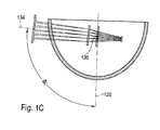
- FIG. 1A to 1C a preferred embodiment of a vandal-proof surveillance camera system 110, which can be mounted to a ceiling 112, is depicted.
- the surveillance camera system 110 comprises a transparent dome 114, which will be described in more detail below.
- the transparent dome 114 comprises an inner surface 116 and an outer surface 118, which both exhibit conical shapes according to a polynomial function as described in more detail below.
- Both, the inner surface 116 and the outer surface 118 are rotationally symmetrical about a symmetry axis 120.
- the first symmetry axis of the outer surface 118 and the second symmetry axis of the inner surface 116 are identical.
- the outer surface 118 exhibits a first apex 122 situated on the symmetry axis 120.
- the inner surface 116 comprises a second apex 124, situated on the symmetry axis 120, too.
- the transparent dome 114 comprises a ring-shaped mounting surface 126, which terminates the transparent dome 114 in an upward direction.
- the transparent dome 114 may be directly mounted to the ceiling 112 via this ring-shaped mounting surface, or an additional mounting block may be mounted in between the transparent dome 114 and the ceiling 112 which e.g. may comprise electronics and/or optical components of the surveillance camera system 110.
- the transparent dome 114 may be mounted on a camera housing, which is part of a camera 128.
- the camera 128 may be mounted to the ceiling 112 or a wall using a separate mounting box or mounting block.
- the surveillance camera system 110 according to the exemplary embodiment in figures 1A to 1C further comprises the camera 128.
- This camera 128 is only symbolically depicted in figures 1A to 1C and comprises a lens system 130 and an image detector 132. Cameras 128 like the one depicted in figures 1A to 1C are known to the person skilled in the art.
- the camera 128 has an optical axis 134.
- the camera 128 is pivotably mounted about a pivot point 136.
- this pivot point 136 is the starting point.
- the pivot point 136 is located on the symmetry axis 120 ⁇ which not necessarily has to be the case.
- the camera 128 may be rotated about this pivot point 136, either manually (e.g. by a surveillance technician) or using a motorized positioning system. It has to noted, that the optical components of the camera 128 are not necessarily drawn to the scale, which explains that the image detector 132 in figures 1A and 1B may be located within the ceiling 112.
- a "perfect" lens system 130 is symbolically used in the optical design, in order to calculate and to take into account lens aberrations of the transparent dome 114.
- the image detector typically resides within the region of the transparent dome 114 rather than the ceiling 112.
- FIGS 1A to 1C different rotational positions of the camera 128 a depicted.
- the angle between the symmetry axis 120 and the optical axis 134 of the camera 128 is denoted by ⁇ .
- ⁇ the angle between the symmetry axis 120 and the optical axis 134 of the camera 128.
- ⁇ the angle between the symmetry axis 120 and the optical axis 134 of the camera 128.
- ⁇ By defmition, in figure 1A , wherein the camera 128 is directed straight down from the ceiling 112, the angle ⁇ equals zero.
- FIG 1B a positioning of the camera 128 exhibiting an angle ⁇ of approximately 40° is depicted.
- the so-called "beyond ceiling view” is depicted, which, in this case, comprises an angle of 95° between optical axis 134 and symmetry axis 120.
- FIG 2 a preferred embodiment of the transparent dome 114 of the surveillance camera system 110 according to figures 1A to 1C is depicted.
- the transparent dome 114 comprises an optical material 138, which, in this exemplary embodiment is made of polycarbonate. Alternatively, a PMMA or other transparent materials, such as transparent plastic materials or glasses, may be used.
- Figure 2 shows several graphs as functions of the distance x (given in mm) between an arbitrary point and the symmetry axis 120, which, in this figure, is identical to the y-axis.
- the inner surface 116 and the outer surface 118 are depicted as functions of the distance x.
- the origin of the y-axis has arbitrarily been chosen to be identical to the first apex 122.
- the thickness of optical material 138 along the symmetry axis 120 i.e. the distance between the first apex 122 and the second apex 124, in this preferred embodiment, has been chosen to be 3.20m. Deviations of approximately up to 0.2mm are tolerable.
- pivot point 136 on the symmetry axis 120 is depicted.
- the pivot point 136 was chosen to be at a y-position of 49.0 mm above the first apex 122.
- Each of these rays 140 includes an angle of ⁇ with the symmetry axis 120, as already mentioned in figures 1A to 1C .
- Each of these viewing rays 140 hits the inner surface 116 of the optical material 138 at an individual point A. The distance between the pivot point 136 and point A depends on the angle ⁇ .
- Graph 142 depicts the separation between the pivot point 136 and point A, i. e. the length of the viewing rays 140, as a function of the distance between point A and the symmetry axis 120, i.e. as a function of the x-coordinate of point A.
- graph 142 exhibits a minimum. For distances x > 40mm, graph 142 rises significantly.
- the variation in the distance 142 between the pivot point 136 and the inner surface 116 shows a variation not exceeding 15% to 20%.
- the knowledge of the position of the minimum of graph 142 is an important factor for mechanical design of the outer dimensions of the camera 128, in order to avoid collision between the camera 128 and the transparent dome 114 during rotation of the camera 128.
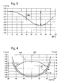
- the thickness variation of the optical material 138 of the transparent dome 140 according to the preferred embodiment as shown in figure 2 is depicted in two different modes.
- the thickness (y-axis, given in mm) is depicted as a function of the angle ⁇ between the symmetry axis 120 and the virtual viewing ray 140 as depicted in figure 2 .
- the thickness is measured perpendicularly to the outer surface 118.
- the thickness (y-axis, given in mm) of the optical material 138 is given as a function of the distance between a point of measurement on the outer surface 118 and the symmetry axis 120 (graph 150).
- graph 148 in figure 3 and graph 150 in figure 4 both describe the thickness of the optical material 138 in different coordinate systems.
- the inner surface 116 and the outer surface 118 of the optical material 138 are depicted again, as a function of the distance x from the symmetry axis 120.
- the right y-axis (given in mm) refers to graphs 116 and 118.
- This thickness variation as depicted in figures 3 and 4 is an important feature of the present invention and contributes to the good optical qualities of the transparent dome 114 according to the invention.
- the thickness function can be calculated from the functions of the outer surface and the inner surface, as given by formula (1) and (2) (see above).
Landscapes
- Physics & Mathematics (AREA)
- General Physics & Mathematics (AREA)
- Studio Devices (AREA)
- Lenses (AREA)
- Prostheses (AREA)
Abstract
Description
- The invention refers to a transparent dome for use in a surveillance camera system, mainly for use in a vandal-proof surveillance camera system. Further, the invention refers to a vandal-proof surveillance camera system comprising a transparent dome according to the invention. Transparent domes and vandal-proof surveillance camera systems can be used, i.e., for indoor and/or outdoor surveillance, such as surveillance of public or private buildings or surveillance of vehicles.
- With the development of modem camera systems, such as digital camera systems, optical surveillance becomes more and more widespread in various fields of technology. Thus, surveillance camera systems nowadays can be found for indoor and/or outdoor surveillance purposes within public or private buildings or within automotive technology, such as for passenger detection and observation.
- In some of these applications, the camera systems are subject to harsh conditions. Thus, for outdoor surveillance purposes, the camera systems typically are subject to rough environmental conditions, such as weather conditions (e.g. rain or snow). For surveillance application purposes, especially of public buildings, the camera systems are subject to mechanical strain, such as exposure to acts of human vandalism, scratches or mechanical shocks.
- In order to protect the camera systems and to extend the lifetime of the systems, surveillance camera systems using a transparent dome as a protection against environmental stress or exposure to human vandalism are known from the state of the art.
JP 2000 156810 A - Nevertheless, optical domes known from prior art usually exhibit various shortcomings or disadvantages. These shortcomings and disadvantages usually are connected with the fact that a camera (including an optical lens system) is placed pivotably within the optical dome. This pivotable mounting of the camera inside the dome ensures that the camera may be aimed arbitrarily, in order to acquire images of arbitrary solid angles selected by the person operating the camera. Either manually or using a pivoting motor, the camera may be directed to point towards a selected object or towards the desired solid angle of space to be monitored.
- Typically, materials such as polycarbonate are used as transparent materials for the transparent domes. Nevertheless, especially when pointing the camera through the transparent dome in a horizontal or nearly horizontal direction, these polycarbonate domes cause color shifts of the images acquired by the camera. Thus, depending on the direction of the optical axis of the camera, especially when acquiring horizontal or near-horizontal views, the image quality of the image acquired by the camera is strongly affected by the wave length. Thus, image distortion depending on the wave length and the angle of the optical axis are unavoidable.
- These image distortions are rather significant when using a cylindrically shaped transparent dome extent, i. e. a dome including a cylindrical portion and a spherical cap. Even the spherically shaped transparent domes as described in
JP 2000 156810 A -
JP 11-308487 - The present invention is defined by a transparent dome according to claim 1.
- The present invention therefore discloses a transparent dome for use in vandal-proof surveillance camera systems avoiding the disadvantages of systems known from the art. Thus, a surveillance camera system is be disclosed, which, while keeping the image quality to an acceptable level, exhibits the benefit of allowing a view along the ceiling surface to which the transparent dome camera is mounted.
- Preferably, the first symmetry axis and the second symmetry axis are identical. Nevertheless, it is preferred if the first symmetry axis and the second symmetry axis are shifted by no more than 0.1mm, most preferably by no more than 0.05mm. Further, it is preferred if the symmetry axes are tilted by no more than 2mrad, most preferably by no more than 1mrad, with respect to each other.
- The optical material exhibits an essentially ring-shaped mounting surface, which can be used in order to mount the transparent dome to a ceiling surface or any other flat surfaces or to a separate mounting block.
- The transparent dome according to the invention is distinguished from transparent domes known from the state of the art by the shape of the inner and the outer surface of the optical material. Both, the outer surface and the inner surface, exhibit non-spherical shapes.
- Preferably, the inner surface and/or the outer surface essentially exhibit the shape of even polynomial functions. Most preferably, these even polynomial functions are order not exceeding eighteen, preferably not exceeding sixteen and most preferably not exceeding fourteen. By "an order not exceeding fourteen" it is to be understood, that polynomial coefficients of higher order than fourteen are negligible (e.g. at least two orders of magnitude smaller) than the polynomial coefficients of the order between two and fourteen. Most preferably, the polynomial coefficients (of dimensionless) of the fourth order and of higher orders are by at least three orders of magnitude and most preferably by at least four orders of magnitude smaller than the second order polynomial coefficients of the polynomial functions of the inner and outer surface.
- Most preferably, the optical material comprises poly-polymethyl methacrylate (PMMA) and/or polycarbonate. Most preferably, the optical material exhibits an index of refraction of approximately n = 1.65 at a wave length of approximately 540 nm. It is advantageous if the optical material is produced in a way that the surface roughness of both the inner and the outer surface is better than 3 diamonds, also denoted as P3 (according to ISO-10110, polish quality), in the optical region. The transparent dome should not contain hazy parts in the optical region.
- The thickness variation from the first apex to the ring-shaped mounting surface may have a maximum of at least 2% variation (i.e. maximum thickness minus minimum thickness, divided by maximum thickness), preferably at least 6% and most preferably 8%. Preferably, the thickness variation does not exceed 10%, depending on the starting point of the optical calculations and other constraints of the optical design. The thickness may exhibit a maximum, preferably a global maximum, at the first apex. Further, the thickness of the optical material may be a polynomial function of the separation x of the point of measurement on the outer surface of the optical material from the first symmetry axis.
- Further, a vandal-proof surveillance camera system comprising a transparent dome according to one of the embodiments described above is disclosed, which further comprises a camera, which is mounted inside the transparent dome. As disclosed above, this camera may comprise an optical sensing system (e.g. a CCD chip or any other imaging system), as well as a lens system. Most preferably, the lens system exhibits an overall focal length greater than 15mm. The camera is pivotably mounted about a pivot point inside the transparent dome. Preferably (but not necessarily), the pivot point is situated on the first or most preferably the second symmetry axis (whereby the first and the second symmetry axis, as disclosed above, preferably are identical). For the positioning of the pivot point, tolerances of 2mm, preferably 1mm, are acceptable. Thus, the pivot point may be situated e.g. 1mm of the first or second symmetry axis.
- The pivot point of the camera may be shifted or arbitrarily chosen along the first or second symmetry axis. Most preferably, the pivot point is chosen at a location along the first or second symmetry axis in a way that the separation between the pivot point and the inner surface of the optical material is approximately constant in any direction accessible by the camera.
- Thus, the pivot point may be chosen in a way that the distance between the pivot point and an arbitrary point on the inner surface located at a distance x from the first or second symmetry axis is a function of x, wherein the graph of this function shows a maximum at x = 0. In other words, the distance between pivot point and the inner surface may be greatest for looking straight down from the pivot point. Most preferably, as indicated above, this maximum is rather "flat" maximum, which means, that the variations between the pivot point and an arbitrary point on the inner surface do not exceed 25%, most preferably 15%, for the angles accessible by camera inside the transparent dome.
- The camera system disclosed above, using the transparent dome according to one of the embodiments as described, has shown to exhibit a good image quality for lenses with focal lengths up to 35mm and for lens openings up to F/2 (F being the diaphragm number, so diaphragm number = 2). Mainly the wall thickness profile of the optical dome as disclosed above makes possible viewing angles beyond ceiling view, e.g. viewing angles (angle between first or second symmetry axis and the direction of view of the camera) of 95° and more.
- Still, the variation of the optical properties resides within tolerable values for these viewing angles. Thus, colour shift and image distortions for these viewing angles exhibit a rather small variation over the range of obtainable viewing angles. This allows e.g. four automatic patten recognition, such as using image processing routines for detecting certain objects within images acquired by surveillance cameras using the transparent dome according to the invention.
- The invention will be described in more details with reference to the drawings given below, in which:
- figures 1A to 1C
- show an exemplary embodiment of a vandal-proof surveillance camera system, the camera pointing into three different directions;
- figure 2
- shows a thickness profile of a transparent dome to be used in a surveillance camera according to
figures 1A to 1C ; - figure 3
- shows the thickness profile of the transparent dome as a function of the viewing angle of the embodiment according to
figure 2 ; and - figure 4
- the thickness profile of the transparent dome according to
figure 2 , given as a function of the distance x from the symmetry axis. - In
figures 1A to 1C a preferred embodiment of a vandal-proofsurveillance camera system 110, which can be mounted to aceiling 112, is depicted. Thesurveillance camera system 110 comprises atransparent dome 114, which will be described in more detail below. Thetransparent dome 114 comprises aninner surface 116 and anouter surface 118, which both exhibit conical shapes according to a polynomial function as described in more detail below. Both, theinner surface 116 and theouter surface 118, are rotationally symmetrical about asymmetry axis 120. Thus, as described above, in this preferred embodiment the first symmetry axis of theouter surface 118 and the second symmetry axis of theinner surface 116 are identical. Further, theouter surface 118 exhibits afirst apex 122 situated on thesymmetry axis 120. Similarly, theinner surface 116 comprises asecond apex 124, situated on thesymmetry axis 120, too. - Further, the
transparent dome 114 comprises a ring-shaped mountingsurface 126, which terminates thetransparent dome 114 in an upward direction. Thetransparent dome 114 may be directly mounted to theceiling 112 via this ring-shaped mounting surface, or an additional mounting block may be mounted in between thetransparent dome 114 and theceiling 112 which e.g. may comprise electronics and/or optical components of thesurveillance camera system 110. Further, thetransparent dome 114 may be mounted on a camera housing, which is part of acamera 128. Thecamera 128 may be mounted to theceiling 112 or a wall using a separate mounting box or mounting block. - The
surveillance camera system 110 according to the exemplary embodiment infigures 1A to 1C further comprises thecamera 128. Thiscamera 128 is only symbolically depicted infigures 1A to 1C and comprises alens system 130 and animage detector 132.Cameras 128 like the one depicted infigures 1A to 1C are known to the person skilled in the art. - The
camera 128 according tofigures 1A to 1C has anoptical axis 134. Thecamera 128 is pivotably mounted about apivot point 136. For optical calculations and design, thispivot point 136 is the starting point. Infigures 1A to 1C , thepivot point 136 is located on thesymmetry axis 120 ― which not necessarily has to be the case. Thecamera 128 may be rotated about thispivot point 136, either manually (e.g. by a surveillance technician) or using a motorized positioning system. It has to noted, that the optical components of thecamera 128 are not necessarily drawn to the scale, which explains that theimage detector 132 infigures 1A and 1B may be located within theceiling 112. Further, a "perfect"lens system 130 is symbolically used in the optical design, in order to calculate and to take into account lens aberrations of thetransparent dome 114. With a "real"lens system 130, the image detector typically resides within the region of thetransparent dome 114 rather than theceiling 112. - In
figures 1A to 1C different rotational positions of the camera 128 a depicted. The angle between thesymmetry axis 120 and theoptical axis 134 of thecamera 128 is denoted by ϕ. By defmition, infigure 1A , wherein thecamera 128 is directed straight down from theceiling 112, the angle ϕ equals zero. Infigure 1B , a positioning of thecamera 128 exhibiting an angle ϕ of approximately 40° is depicted. Infigure 1C , the so-called "beyond ceiling view" is depicted, which, in this case, comprises an angle of 95° betweenoptical axis 134 andsymmetry axis 120. The grate advantage of thesurveillance camera system 110 using the conically-shapedtransparent dome 114 according tofigures 1A to 1C is that ceiling-views of angles ϕ ≥ 90° may be achieved without major image distortions or image deteriorations. - In
figure 2 , a preferred embodiment of thetransparent dome 114 of thesurveillance camera system 110 according tofigures 1A to 1C is depicted. Thetransparent dome 114 comprises anoptical material 138, which, in this exemplary embodiment is made of polycarbonate. Alternatively, a PMMA or other transparent materials, such as transparent plastic materials or glasses, may be used. -
Figure 2 shows several graphs as functions of the distance x (given in mm) between an arbitrary point and thesymmetry axis 120, which, in this figure, is identical to the y-axis. First, infigure 2 theinner surface 116 and theouter surface 118 are depicted as functions of the distance x. In this graph according tofigure 2 , the origin of the y-axis has arbitrarily been chosen to be identical to thefirst apex 122. The thickness ofoptical material 138 along thesymmetry axis 120, i.e. the distance between thefirst apex 122 and thesecond apex 124, in this preferred embodiment, has been chosen to be 3.20m. Deviations of approximately up to 0.2mm are tolerable. - The functional shape of the
inner surface 116 and theouter surface 118 was optimized by minimizing optical distortions and chromatically apparitions over the visible spectrum and the near infrared spectrum using commercially available optical optimization software. Thus, for this preferred embodiment of the invention, theouter surface 118 was chosen to have a theoretical shape according to the following function:
- Similarly, the
inner surface 116 was chosen to have a theoretical shape according to the following function:
- Nevertheless, since these are theoretical functions, variations in the functional values o(x) and/or i(x) of approximately ±0.05 mm are estimated to be tolerable, most preferably 0.02 mm, still leading to tolerable optical results.
- Further, in
figure 2 thepivot point 136 on thesymmetry axis 120 is depicted. In this preferred exemplary embodiment, according tofigure 2 , thepivot point 136 was chosen to be at a y-position of 49.0 mm above thefirst apex 122. - Further various viewing directions are indicated in
figure 2 by virtual "viewing rays" 140. Each of these rays 140 includes an angle of ϕ with thesymmetry axis 120, as already mentioned infigures 1A to 1C . Each of these viewing rays 140 hits theinner surface 116 of theoptical material 138 at an individual point A. The distance between thepivot point 136 and point A depends on the angle ϕ. -
Graph 142 depicts the separation between thepivot point 136 and point A, i. e. the length of the viewing rays 140, as a function of the distance between point A and thesymmetry axis 120, i.e. as a function of the x-coordinate of point A. As can be seen, for this choice of thepivot point 136 as depicted infigure 2 graph 142 exhibits rather flat maximum 144 on thesymmetry axis 120, i.e. at x = 0. At approximately x = 40mm, which corresponds to an angle of ϕ = 70°, graph 142 exhibits a minimum. For distances x > 40mm,graph 142 rises significantly. Nevertheless, for angles up to about 95°, the variation in thedistance 142 between thepivot point 136 and theinner surface 116 shows a variation not exceeding 15% to 20%. The knowledge of the position of the minimum ofgraph 142 is an important factor for mechanical design of the outer dimensions of thecamera 128, in order to avoid collision between thecamera 128 and thetransparent dome 114 during rotation of thecamera 128. - In
figures 3 and 4 , the thickness variation of theoptical material 138 of the transparent dome 140 according to the preferred embodiment as shown infigure 2 is depicted in two different modes. Thus, infigure 3 , the thickness (y-axis, given in mm) is depicted as a function of the angle ϕ between thesymmetry axis 120 and the virtual viewing ray 140 as depicted infigure 2 . Here, as infigure 4 , the thickness is measured perpendicularly to theouter surface 118. - In
figure 4 , the thickness (y-axis, given in mm) of theoptical material 138 is given as a function of the distance between a point of measurement on theouter surface 118 and the symmetry axis 120 (graph 150). Thus,graph 148 infigure 3 andgraph 150 infigure 4 both describe the thickness of theoptical material 138 in different coordinate systems. - Further, in
figure 4 , theinner surface 116 and theouter surface 118 of theoptical material 138 are depicted again, as a function of the distance x from thesymmetry axis 120. The right y-axis (given in mm) refers tographs - As can be seen from
figures 3 and 4 ,graphs optical material 138, exhibit a maximum at ϕ = 0 or x = 0, respectively. At approximately ϕ = 70° or x = 40mm, respectively, thethickness figure 3 , the difference Δ between the minimum and the maximum is approximately 0.27mm. Thus, the overall variation of the thickness in this exemplary embodiment is 0.27mm divided by 3.20mm, which corresponds to approximately 8.4%. This thickness variation as depicted infigures 3 and 4 is an important feature of the present invention and contributes to the good optical qualities of thetransparent dome 114 according to the invention. The thickness function can be calculated from the functions of the outer surface and the inner surface, as given by formula (1) and (2) (see above).
Claims (9)
- Transparent dome (114) for use in a vandal-proof surveillance camera system (110) comprising a transparent optical material (138), the transparent optical material (138) (138) comprising an inner surface (116) and an outer surface (118), wherein the outer surface (118) essentially is rotationally symmetrical about a first symmetry axis (120), wherein a first apex (122) of the outer surface (118) is located on the first symmetry axis (120), wherein the inner surface (116) essentially is rotationally symmetrical about a second symmetry axis (120), wherein a second apex (124) of the inner surface (116) is located on the second symmetry axis (120), wherein the first symmetry axis (120) and the second symmetry axis (120) are essentially parallel, and wherein both the outer surface (118) and the inner surface (116) exhibit non-spherical shapes,
characterized in that the inner surface (116) and the outer surface (118) are shaped that the transparent optical material (138) exhibits a thickness variation, whereby the shape of the inner surface (116) and the outer surface (118) are optimized by minimizing optical distortions. - Transparent dome (114) according to the previous claim, characterized in the outer surface (118) and/or the inner surface (116) essentially exhibit the shape of even polynomial functions o(x), i(x).
- Transparent dome (114) according to the previous claim, the polynomial functions o(x), i(x) being of an order not exceeding 18, preferably not exceeding 16, and most preferably not exceeding 14.
- Transparent dome (114) according to one of the two preceding claims, characterized in that the dimensional polynomial coefficients of the polynomial functions o(x), i(x) of the fourth order and of higher order are by at least three orders of magnitude, preferably by at least four orders of magnitude smaller than the second order polynomial coefficients of the polynomial functions o(x), i(x).
- Transparent dome (114) according to claim 1, wherein the relative thickness variation over the transparent dome (114) is at least 2%, preferably at least 6% and most preferably at least 8%, and preferably does not exceed 10%.
- Transparent dome (114) according to claim 1 or 5, characterized in that the thickness exhibits a maximum, preferably a global maximum, at the first apex.
- Transparent dome (114) according to claim 1, 5 or 6, characterized in that the thickness at a point on the outer surface (118) being separated by a distance x from the first symmetry axis is a polynomial function f(x).
- Vandal-proof surveillance camera system (110), comprising a transparent dome (114) according to one of the preceding claims and a camera (128) being mounted inside the transparent dome (114), wherein the camera (128) is pivotable about by a pivot point (136).
- Vandal-proof surveillance camera system (110) according to the preceding claim characterized in that the pivot point (136) is situated on the second symmetry axis (120).
Priority Applications (7)
| Application Number | Priority Date | Filing Date | Title |
|---|---|---|---|
| ES05104771T ES2308382T3 (en) | 2005-06-02 | 2005-06-02 | AS WITH OPTICAL CORRECTION. |
| PT05104771T PT1729269E (en) | 2005-06-02 | 2005-06-02 | OPTICAL CORRECTION CUP |
| DE602005008724T DE602005008724D1 (en) | 2005-06-02 | 2005-06-02 | Dome with optical correction |
| AT05104771T ATE403922T1 (en) | 2005-06-02 | 2005-06-02 | DOME WITH OPTICAL CORRECTION |
| EP05104771A EP1729269B1 (en) | 2005-06-02 | 2005-06-02 | Dome with optical correction |
| CN2006100071623A CN1873515B (en) | 2005-06-02 | 2006-02-06 | Hood with optical correction |
| US11/351,086 US20060177217A1 (en) | 2005-02-06 | 2006-02-09 | Dome with optical correction |
Applications Claiming Priority (1)
| Application Number | Priority Date | Filing Date | Title |
|---|---|---|---|
| EP05104771A EP1729269B1 (en) | 2005-06-02 | 2005-06-02 | Dome with optical correction |
Publications (2)
| Publication Number | Publication Date |
|---|---|
| EP1729269A1 EP1729269A1 (en) | 2006-12-06 |
| EP1729269B1 true EP1729269B1 (en) | 2008-08-06 |
Family
ID=35106699
Family Applications (1)
| Application Number | Title | Priority Date | Filing Date |
|---|---|---|---|
| EP05104771A Expired - Lifetime EP1729269B1 (en) | 2005-02-06 | 2005-06-02 | Dome with optical correction |
Country Status (7)
| Country | Link |
|---|---|
| US (1) | US20060177217A1 (en) |
| EP (1) | EP1729269B1 (en) |
| CN (1) | CN1873515B (en) |
| AT (1) | ATE403922T1 (en) |
| DE (1) | DE602005008724D1 (en) |
| ES (1) | ES2308382T3 (en) |
| PT (1) | PT1729269E (en) |
Families Citing this family (16)
| Publication number | Priority date | Publication date | Assignee | Title |
|---|---|---|---|---|
| JP4979285B2 (en) * | 2006-07-07 | 2012-07-18 | パナソニック株式会社 | Dome-type surveillance camera device |
| JP4231075B2 (en) * | 2006-10-30 | 2009-02-25 | パナソニック株式会社 | Surveillance camera device |
| JP4270267B2 (en) * | 2006-11-29 | 2009-05-27 | ソニー株式会社 | Lens barrel rotation type imaging device |
| US8610773B2 (en) | 2010-07-07 | 2013-12-17 | Honeywell International Inc. | CCTV camera housing |
| US9122049B2 (en) * | 2010-12-30 | 2015-09-01 | Pelco, Inc. | Optical compensation in surveillance domes |
| WO2013060370A1 (en) | 2011-10-27 | 2013-05-02 | Robert Bosch Gmbh | Front cover for a housing enclosing a camera |
| WO2013060373A1 (en) | 2011-10-27 | 2013-05-02 | Robert Bosch Gmbh | Method of controlling a cooling arrangement |
| WO2013060369A1 (en) | 2011-10-27 | 2013-05-02 | Robert Bosch Gmbh | Adjustment arrangement |
| WO2013060371A1 (en) | 2011-10-27 | 2013-05-02 | Robert Bosch Gmbh | Adjustment arrangement |
| CN102917166A (en) * | 2012-11-20 | 2013-02-06 | 无锡成电科大科技发展有限公司 | Breakage-proof security monitoring device |
| CN102917165A (en) * | 2012-11-20 | 2013-02-06 | 无锡成电科大科技发展有限公司 | Security and safety camera with transparent protective cover |
| CN107407861B (en) * | 2015-03-26 | 2019-10-29 | 富士胶片株式会社 | camera device |
| CN107430318B (en) * | 2015-03-31 | 2020-03-24 | 富士胶片株式会社 | Ball camera and ball cover |
| JP6818531B2 (en) * | 2016-12-05 | 2021-01-20 | キヤノン株式会社 | Imaging optical system and an imaging device having it |
| US11150543B2 (en) | 2018-01-22 | 2021-10-19 | Hangzhou Hikvision Digital Technology Co., Ltd. | Transparent cover and imaging optical system |
| EP4391566A1 (en) * | 2022-12-22 | 2024-06-26 | Samcon Prozessleittechnik GmbH | Protective housing for a monitoring camera system and monitoring camera system |
Family Cites Families (12)
| Publication number | Priority date | Publication date | Assignee | Title |
|---|---|---|---|---|
| US5394184A (en) * | 1993-08-30 | 1995-02-28 | Sensormatic Electronics Corporation | Surveillance assembly having circumferential delivery of forced air to viewing bubble |
| US5625495A (en) * | 1994-12-07 | 1997-04-29 | U.S. Precision Lens Inc. | Telecentric lens systems for forming an image of an object composed of pixels |
| FR2740245B1 (en) * | 1995-10-24 | 1997-12-26 | Saubade Jacques | DEVICE FOR CAPTURING AND TRANSMITTING IMAGES, AND REMOTE MONITORING INSTALLATION COMPRISING SUCH A DEVICE |
| CN2256199Y (en) * | 1995-12-12 | 1997-06-11 | 陈建湘 | Integrated vedio camera with internal universal pan and tilt head |
| JPH11308487A (en) * | 1998-04-21 | 1999-11-05 | Toshiba Corp | Camera device |
| JP4182577B2 (en) | 1998-11-20 | 2008-11-19 | ソニー株式会社 | Dome cover and dome cover molding equipment |
| JP2000156806A (en) * | 1998-11-20 | 2000-06-06 | Sony Corp | Video camera equipment |
| US6349004B1 (en) * | 1999-07-16 | 2002-02-19 | Optics 1, Inc. | Head mounted display viewing optics with improved optical performance |
| WO2001075833A2 (en) * | 2000-04-04 | 2001-10-11 | Videolarm, Inc. | Pressurized camera housing |
| NL1024286C2 (en) * | 2003-09-12 | 2005-03-15 | Bosch Gmbh Robert | Observing device. |
| US7491002B2 (en) * | 2004-03-29 | 2009-02-17 | Criterion Technology, Inc. | Spherical enclosure for a camera |
| US7306383B2 (en) * | 2004-07-27 | 2007-12-11 | Robert Bosch Gmbh | Compound dome window for a surveillance camera |
-
2005
- 2005-06-02 ES ES05104771T patent/ES2308382T3/en not_active Expired - Lifetime
- 2005-06-02 DE DE602005008724T patent/DE602005008724D1/en not_active Expired - Lifetime
- 2005-06-02 PT PT05104771T patent/PT1729269E/en unknown
- 2005-06-02 EP EP05104771A patent/EP1729269B1/en not_active Expired - Lifetime
- 2005-06-02 AT AT05104771T patent/ATE403922T1/en not_active IP Right Cessation
-
2006
- 2006-02-06 CN CN2006100071623A patent/CN1873515B/en not_active Expired - Fee Related
- 2006-02-09 US US11/351,086 patent/US20060177217A1/en not_active Abandoned
Also Published As
| Publication number | Publication date |
|---|---|
| US20060177217A1 (en) | 2006-08-10 |
| ATE403922T1 (en) | 2008-08-15 |
| CN1873515B (en) | 2010-11-10 |
| PT1729269E (en) | 2008-09-09 |
| DE602005008724D1 (en) | 2008-09-18 |
| CN1873515A (en) | 2006-12-06 |
| ES2308382T3 (en) | 2008-12-01 |
| EP1729269A1 (en) | 2006-12-06 |
Similar Documents
| Publication | Publication Date | Title |
|---|---|---|
| EP1729269A1 (en) | Dome with optical correction | |
| US7399095B2 (en) | Apparatus for mounting a panoramic mirror | |
| US20250083616A1 (en) | Glass for vehicles and camera unit | |
| US7649690B2 (en) | Integrated panoramic and forward optical device, system and method for omnidirectional signal processing | |
| KR20090026712A (en) | Lens, lens unit and imaging device for far infrared camera | |
| CN114126924B (en) | Exterior trim part for vehicle and exterior trim part for vehicle with far infrared camera | |
| JP5065159B2 (en) | Imaging lens and imaging apparatus | |
| KR101070991B1 (en) | Fisheye lens | |
| CN101387737A (en) | Far-infrared imaging lens, lens unit and imaging device | |
| WO2015004479A2 (en) | Adapter and casing apparatus for an imaging device | |
| KR20120076210A (en) | Fisheye lens | |
| JP2008268281A (en) | Infrared lens group, infrared camera, night driving support system | |
| JP2007199573A (en) | Infrared lens, infrared camera and night vision | |
| EP1916838A1 (en) | Integrated multiple imaging device | |
| JP2020003584A (en) | Lens unit and camera module | |
| JP2019101146A (en) | Imaging lens and imaging device including the same | |
| KR20210136983A (en) | High-Wide Angle Observation Accessories for Infrared Detectors | |
| KR100972528B1 (en) | Fisheye lens that can replace some lens elements on the object side | |
| Ohte et al. | A practical spherical mirror omnidirectional camera | |
| Kweon et al. | Design of a mega-pixel grade catadioptric panoramic lens with the rectilinear projection scheme | |
| JP2023128310A (en) | Wide-angle lens units, camera modules, imaging systems, and moving objects | |
| WO2023140143A1 (en) | Imaging lens system, camera module, vehicle-mounted system, and mobile object | |
| KR20090089162A (en) | Omnidirectional surveillance camera optical system using prism | |
| GB2277603A (en) | Viewing system having aspheric lens element | |
| MXPA00005531A (en) | An omnidirectional imaging apparatus |
Legal Events
| Date | Code | Title | Description |
|---|---|---|---|
| PUAI | Public reference made under article 153(3) epc to a published international application that has entered the european phase |
Free format text: ORIGINAL CODE: 0009012 |
|
| AK | Designated contracting states |
Kind code of ref document: A1 Designated state(s): AT BE BG CH CY CZ DE DK EE ES FI FR GB GR HU IE IS IT LI LT LU MC NL PL PT RO SE SI SK TR |
|
| AX | Request for extension of the european patent |
Extension state: AL BA HR LV MK YU |
|
| 17P | Request for examination filed |
Effective date: 20070606 |
|
| AKX | Designation fees paid |
Designated state(s): AT BE BG CH CY CZ DE DK EE ES FI FR GB GR HU IE IS IT LI LT LU MC NL PL PT RO SE SI SK TR |
|
| 17Q | First examination report despatched |
Effective date: 20070816 |
|
| GRAP | Despatch of communication of intention to grant a patent |
Free format text: ORIGINAL CODE: EPIDOSNIGR1 |
|
| GRAS | Grant fee paid |
Free format text: ORIGINAL CODE: EPIDOSNIGR3 |
|
| GRAA | (expected) grant |
Free format text: ORIGINAL CODE: 0009210 |
|
| AK | Designated contracting states |
Kind code of ref document: B1 Designated state(s): AT BE BG CH CY CZ DE DK EE ES FI FR GB GR HU IE IS IT LI LT LU MC NL PL PT RO SE SI SK TR |
|
| REG | Reference to a national code |
Ref country code: GB Ref legal event code: FG4D |
|
| REG | Reference to a national code |
Ref country code: CH Ref legal event code: EP |
|
| REG | Reference to a national code |
Ref country code: PT Ref legal event code: SC4A Free format text: AVAILABILITY OF NATIONAL TRANSLATION Effective date: 20080828 |
|
| REG | Reference to a national code |
Ref country code: IE Ref legal event code: FG4D |
|
| REF | Corresponds to: |
Ref document number: 602005008724 Country of ref document: DE Date of ref document: 20080918 Kind code of ref document: P |
|
| REG | Reference to a national code |
Ref country code: ES Ref legal event code: FG2A Ref document number: 2308382 Country of ref document: ES Kind code of ref document: T3 |
|
| PG25 | Lapsed in a contracting state [announced via postgrant information from national office to epo] |
Ref country code: IS Free format text: LAPSE BECAUSE OF FAILURE TO SUBMIT A TRANSLATION OF THE DESCRIPTION OR TO PAY THE FEE WITHIN THE PRESCRIBED TIME-LIMIT Effective date: 20081206 Ref country code: LT Free format text: LAPSE BECAUSE OF FAILURE TO SUBMIT A TRANSLATION OF THE DESCRIPTION OR TO PAY THE FEE WITHIN THE PRESCRIBED TIME-LIMIT Effective date: 20080806 |
|
| PG25 | Lapsed in a contracting state [announced via postgrant information from national office to epo] |
Ref country code: SI Free format text: LAPSE BECAUSE OF FAILURE TO SUBMIT A TRANSLATION OF THE DESCRIPTION OR TO PAY THE FEE WITHIN THE PRESCRIBED TIME-LIMIT Effective date: 20080806 Ref country code: AT Free format text: LAPSE BECAUSE OF FAILURE TO SUBMIT A TRANSLATION OF THE DESCRIPTION OR TO PAY THE FEE WITHIN THE PRESCRIBED TIME-LIMIT Effective date: 20080806 Ref country code: FI Free format text: LAPSE BECAUSE OF FAILURE TO SUBMIT A TRANSLATION OF THE DESCRIPTION OR TO PAY THE FEE WITHIN THE PRESCRIBED TIME-LIMIT Effective date: 20080806 |
|
| PG25 | Lapsed in a contracting state [announced via postgrant information from national office to epo] |
Ref country code: BG Free format text: LAPSE BECAUSE OF FAILURE TO SUBMIT A TRANSLATION OF THE DESCRIPTION OR TO PAY THE FEE WITHIN THE PRESCRIBED TIME-LIMIT Effective date: 20081106 Ref country code: DK Free format text: LAPSE BECAUSE OF FAILURE TO SUBMIT A TRANSLATION OF THE DESCRIPTION OR TO PAY THE FEE WITHIN THE PRESCRIBED TIME-LIMIT Effective date: 20080806 |
|
| PG25 | Lapsed in a contracting state [announced via postgrant information from national office to epo] |
Ref country code: SK Free format text: LAPSE BECAUSE OF FAILURE TO SUBMIT A TRANSLATION OF THE DESCRIPTION OR TO PAY THE FEE WITHIN THE PRESCRIBED TIME-LIMIT Effective date: 20080806 Ref country code: CZ Free format text: LAPSE BECAUSE OF FAILURE TO SUBMIT A TRANSLATION OF THE DESCRIPTION OR TO PAY THE FEE WITHIN THE PRESCRIBED TIME-LIMIT Effective date: 20080806 Ref country code: RO Free format text: LAPSE BECAUSE OF FAILURE TO SUBMIT A TRANSLATION OF THE DESCRIPTION OR TO PAY THE FEE WITHIN THE PRESCRIBED TIME-LIMIT Effective date: 20080806 |
|
| PLBE | No opposition filed within time limit |
Free format text: ORIGINAL CODE: 0009261 |
|
| STAA | Information on the status of an ep patent application or granted ep patent |
Free format text: STATUS: NO OPPOSITION FILED WITHIN TIME LIMIT |
|
| 26N | No opposition filed |
Effective date: 20090507 |
|
| PG25 | Lapsed in a contracting state [announced via postgrant information from national office to epo] |
Ref country code: EE Free format text: LAPSE BECAUSE OF FAILURE TO SUBMIT A TRANSLATION OF THE DESCRIPTION OR TO PAY THE FEE WITHIN THE PRESCRIBED TIME-LIMIT Effective date: 20080806 |
|
| PG25 | Lapsed in a contracting state [announced via postgrant information from national office to epo] |
Ref country code: SE Free format text: LAPSE BECAUSE OF FAILURE TO SUBMIT A TRANSLATION OF THE DESCRIPTION OR TO PAY THE FEE WITHIN THE PRESCRIBED TIME-LIMIT Effective date: 20081106 Ref country code: MC Free format text: LAPSE BECAUSE OF NON-PAYMENT OF DUE FEES Effective date: 20090630 |
|
| REG | Reference to a national code |
Ref country code: CH Ref legal event code: PL |
|
| REG | Reference to a national code |
Ref country code: IE Ref legal event code: MM4A |
|
| PG25 | Lapsed in a contracting state [announced via postgrant information from national office to epo] |
Ref country code: LI Free format text: LAPSE BECAUSE OF NON-PAYMENT OF DUE FEES Effective date: 20090630 Ref country code: CH Free format text: LAPSE BECAUSE OF NON-PAYMENT OF DUE FEES Effective date: 20090630 Ref country code: IE Free format text: LAPSE BECAUSE OF NON-PAYMENT OF DUE FEES Effective date: 20090602 |
|
| PG25 | Lapsed in a contracting state [announced via postgrant information from national office to epo] |
Ref country code: PL Free format text: LAPSE BECAUSE OF FAILURE TO SUBMIT A TRANSLATION OF THE DESCRIPTION OR TO PAY THE FEE WITHIN THE PRESCRIBED TIME-LIMIT Effective date: 20080806 |
|
| PG25 | Lapsed in a contracting state [announced via postgrant information from national office to epo] |
Ref country code: GR Free format text: LAPSE BECAUSE OF FAILURE TO SUBMIT A TRANSLATION OF THE DESCRIPTION OR TO PAY THE FEE WITHIN THE PRESCRIBED TIME-LIMIT Effective date: 20081107 |
|
| PG25 | Lapsed in a contracting state [announced via postgrant information from national office to epo] |
Ref country code: LU Free format text: LAPSE BECAUSE OF NON-PAYMENT OF DUE FEES Effective date: 20090602 |
|
| PG25 | Lapsed in a contracting state [announced via postgrant information from national office to epo] |
Ref country code: HU Free format text: LAPSE BECAUSE OF FAILURE TO SUBMIT A TRANSLATION OF THE DESCRIPTION OR TO PAY THE FEE WITHIN THE PRESCRIBED TIME-LIMIT Effective date: 20090207 |
|
| PG25 | Lapsed in a contracting state [announced via postgrant information from national office to epo] |
Ref country code: TR Free format text: LAPSE BECAUSE OF FAILURE TO SUBMIT A TRANSLATION OF THE DESCRIPTION OR TO PAY THE FEE WITHIN THE PRESCRIBED TIME-LIMIT Effective date: 20080806 |
|
| PG25 | Lapsed in a contracting state [announced via postgrant information from national office to epo] |
Ref country code: CY Free format text: LAPSE BECAUSE OF FAILURE TO SUBMIT A TRANSLATION OF THE DESCRIPTION OR TO PAY THE FEE WITHIN THE PRESCRIBED TIME-LIMIT Effective date: 20080806 |
|
| REG | Reference to a national code |
Ref country code: FR Ref legal event code: PLFP Year of fee payment: 12 |
|
| REG | Reference to a national code |
Ref country code: FR Ref legal event code: PLFP Year of fee payment: 13 |
|
| REG | Reference to a national code |
Ref country code: FR Ref legal event code: PLFP Year of fee payment: 14 |
|
| PGFP | Annual fee paid to national office [announced via postgrant information from national office to epo] |
Ref country code: PT Payment date: 20200526 Year of fee payment: 16 |
|
| PGFP | Annual fee paid to national office [announced via postgrant information from national office to epo] |
Ref country code: BE Payment date: 20200622 Year of fee payment: 16 |
|
| PG25 | Lapsed in a contracting state [announced via postgrant information from national office to epo] |
Ref country code: PT Free format text: LAPSE BECAUSE OF NON-PAYMENT OF DUE FEES Effective date: 20211202 |
|
| REG | Reference to a national code |
Ref country code: BE Ref legal event code: MM Effective date: 20210630 |
|
| PG25 | Lapsed in a contracting state [announced via postgrant information from national office to epo] |
Ref country code: BE Free format text: LAPSE BECAUSE OF NON-PAYMENT OF DUE FEES Effective date: 20210630 |
|
| PGFP | Annual fee paid to national office [announced via postgrant information from national office to epo] |
Ref country code: NL Payment date: 20220621 Year of fee payment: 18 Ref country code: GB Payment date: 20220623 Year of fee payment: 18 |
|
| PGFP | Annual fee paid to national office [announced via postgrant information from national office to epo] |
Ref country code: FR Payment date: 20220621 Year of fee payment: 18 |
|
| PGFP | Annual fee paid to national office [announced via postgrant information from national office to epo] |
Ref country code: IT Payment date: 20220630 Year of fee payment: 18 Ref country code: ES Payment date: 20220719 Year of fee payment: 18 Ref country code: DE Payment date: 20220822 Year of fee payment: 18 |
|
| REG | Reference to a national code |
Ref country code: DE Ref legal event code: R119 Ref document number: 602005008724 Country of ref document: DE |
|
| REG | Reference to a national code |
Ref country code: NL Ref legal event code: MM Effective date: 20230701 |
|
| GBPC | Gb: european patent ceased through non-payment of renewal fee |
Effective date: 20230602 |
|
| PG25 | Lapsed in a contracting state [announced via postgrant information from national office to epo] |
Ref country code: NL Free format text: LAPSE BECAUSE OF NON-PAYMENT OF DUE FEES Effective date: 20230701 |
|
| PG25 | Lapsed in a contracting state [announced via postgrant information from national office to epo] |
Ref country code: DE Free format text: LAPSE BECAUSE OF NON-PAYMENT OF DUE FEES Effective date: 20240103 Ref country code: GB Free format text: LAPSE BECAUSE OF NON-PAYMENT OF DUE FEES Effective date: 20230602 |
|
| PG25 | Lapsed in a contracting state [announced via postgrant information from national office to epo] |
Ref country code: FR Free format text: LAPSE BECAUSE OF NON-PAYMENT OF DUE FEES Effective date: 20230630 |
|
| REG | Reference to a national code |
Ref country code: ES Ref legal event code: FD2A Effective date: 20240729 |
|
| PG25 | Lapsed in a contracting state [announced via postgrant information from national office to epo] |
Ref country code: IT Free format text: LAPSE BECAUSE OF NON-PAYMENT OF DUE FEES Effective date: 20230602 |
|
| PG25 | Lapsed in a contracting state [announced via postgrant information from national office to epo] |
Ref country code: ES Free format text: LAPSE BECAUSE OF NON-PAYMENT OF DUE FEES Effective date: 20230603 |
|
| PG25 | Lapsed in a contracting state [announced via postgrant information from national office to epo] |
Ref country code: ES Free format text: LAPSE BECAUSE OF NON-PAYMENT OF DUE FEES Effective date: 20230603 |